EP1745895B1 - Apparatus for three-side trimming - Google Patents
Apparatus for three-side trimming Download PDFInfo
- Publication number
- EP1745895B1 EP1745895B1 EP06116691A EP06116691A EP1745895B1 EP 1745895 B1 EP1745895 B1 EP 1745895B1 EP 06116691 A EP06116691 A EP 06116691A EP 06116691 A EP06116691 A EP 06116691A EP 1745895 B1 EP1745895 B1 EP 1745895B1
- Authority
- EP
- European Patent Office
- Prior art keywords
- movement
- product
- lifting
- alignment
- cutting position
- Prior art date
- Legal status (The legal status is an assumption and is not a legal conclusion. Google has not performed a legal analysis and makes no representation as to the accuracy of the status listed.)
- Active
Links
- 238000009966 trimming Methods 0.000 title claims description 20
- 230000000977 initiatory effect Effects 0.000 claims abstract description 10
- 230000035939 shock Effects 0.000 description 2
- 238000004904 shortening Methods 0.000 description 2
- 230000006978 adaptation Effects 0.000 description 1
- 125000004122 cyclic group Chemical group 0.000 description 1
- 230000001419 dependent effect Effects 0.000 description 1
- 238000004519 manufacturing process Methods 0.000 description 1
- 230000009347 mechanical transmission Effects 0.000 description 1
Images
Classifications
-
- B—PERFORMING OPERATIONS; TRANSPORTING
- B26—HAND CUTTING TOOLS; CUTTING; SEVERING
- B26D—CUTTING; DETAILS COMMON TO MACHINES FOR PERFORATING, PUNCHING, CUTTING-OUT, STAMPING-OUT OR SEVERING
- B26D7/00—Details of apparatus for cutting, cutting-out, stamping-out, punching, perforating, or severing by means other than cutting
- B26D7/01—Means for holding or positioning work
- B26D7/015—Means for holding or positioning work for sheet material or piles of sheets
-
- B—PERFORMING OPERATIONS; TRANSPORTING
- B26—HAND CUTTING TOOLS; CUTTING; SEVERING
- B26D—CUTTING; DETAILS COMMON TO MACHINES FOR PERFORATING, PUNCHING, CUTTING-OUT, STAMPING-OUT OR SEVERING
- B26D1/00—Cutting through work characterised by the nature or movement of the cutting member or particular materials not otherwise provided for; Apparatus or machines therefor; Cutting members therefor
- B26D1/01—Cutting through work characterised by the nature or movement of the cutting member or particular materials not otherwise provided for; Apparatus or machines therefor; Cutting members therefor involving a cutting member which does not travel with the work
- B26D1/04—Cutting through work characterised by the nature or movement of the cutting member or particular materials not otherwise provided for; Apparatus or machines therefor; Cutting members therefor involving a cutting member which does not travel with the work having a linearly-movable cutting member
- B26D1/06—Cutting through work characterised by the nature or movement of the cutting member or particular materials not otherwise provided for; Apparatus or machines therefor; Cutting members therefor involving a cutting member which does not travel with the work having a linearly-movable cutting member wherein the cutting member reciprocates
- B26D1/08—Cutting through work characterised by the nature or movement of the cutting member or particular materials not otherwise provided for; Apparatus or machines therefor; Cutting members therefor involving a cutting member which does not travel with the work having a linearly-movable cutting member wherein the cutting member reciprocates of the guillotine type
- B26D1/09—Cutting through work characterised by the nature or movement of the cutting member or particular materials not otherwise provided for; Apparatus or machines therefor; Cutting members therefor involving a cutting member which does not travel with the work having a linearly-movable cutting member wherein the cutting member reciprocates of the guillotine type with a plurality of cutting members
-
- B—PERFORMING OPERATIONS; TRANSPORTING
- B26—HAND CUTTING TOOLS; CUTTING; SEVERING
- B26D—CUTTING; DETAILS COMMON TO MACHINES FOR PERFORATING, PUNCHING, CUTTING-OUT, STAMPING-OUT OR SEVERING
- B26D7/00—Details of apparatus for cutting, cutting-out, stamping-out, punching, perforating, or severing by means other than cutting
- B26D2007/0012—Details, accessories or auxiliary or special operations not otherwise provided for
- B26D2007/0081—Cutting on three sides, e.g. trilateral trimming
-
- B—PERFORMING OPERATIONS; TRANSPORTING
- B26—HAND CUTTING TOOLS; CUTTING; SEVERING
- B26D—CUTTING; DETAILS COMMON TO MACHINES FOR PERFORATING, PUNCHING, CUTTING-OUT, STAMPING-OUT OR SEVERING
- B26D5/00—Arrangements for operating and controlling machines or devices for cutting, cutting-out, stamping-out, punching, perforating, or severing by means other than cutting
Definitions
- the invention relates to a device for the simultaneous three-sided trimming of products, in particular brochures according to the preamble of claim 1.
- a device for the simultaneous three-sided trimming of products in particular brochures according to the preamble of claim 1.
- Such a device is in US RE 28840 E disclosed.
- such a device for three-sided trimming comprises means for initiating and / or terminating the thrust movement of the alignment device such that the time of initiation and / or the burst duration of the thrust movement within the cycle time of the device is independent of the lifting movement of the lifting device.
- This decoupling of the cutting movement from the impact movement makes it possible to make better use of the time available overall for the three-sided trimming of the product.
- the alignment device is associated with a separate drive, wherein the device comprises a controller which controls the drive of the alignment device independently of the lifting movement of the lifting device. This eliminates the costly deriving the shock movement of the lifting movement of the lifting device, such as a mechanical cam gear.
- product-dependent optimized electronic control curves can be stored in the control for driving the alignment device.
- the apparatus comprises a transport device which brings the product into a first cutting position and from a first cutting position to a second cutting position within a transport time.
- this transport time has a minimum, which should not be undershot, because otherwise the slowing down of the product in the cutting position is made more difficult by the correspondingly increased transport speed.
- the control of the alignment device is designed such that it determines the time of initiation and / or termination of the thrust movement of the alignment device such that substantially does not increase the transport time of the product at a shortening of the stroke duration of the lifting movement of the lifting device.
- a leading edge stop for the product is at least temporarily arranged in the region of a first cutting position of the device.
- this leading edge stop is swung out of the transport plane in the remaining time in order not to hinder the other movements in the device.
- the thrust movement of the pusher takes place during the transport movement of the transport device.
- the transport device is advantageously operated such that the product is already braked somewhat before reaching the leading edge stop and the transport device continues to drive the product against the leading edge stop at a reduced speed during the lateral pushing movement.
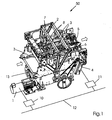
- FIG Fig. 1 A representative example of a cutting device for three-sided trimming of products is shown in FIG Fig. 1 shown.
- a first drive motor 1 realizes the movement of the knife lifting device 2, to which the blades 3 are fastened.
- the product running direction is indicated by arrows.
- a second drive motor 4 drives the belts 7, 8 of the transport device 9 via a first and second drive shaft 5, 6.
- control units 10, 11 are provided which can communicate with each other by means of a connection for exchanging data and / or control signals 12.
- the connection 12 can also lead to a machine control unit and for controlling the alignment device 42.
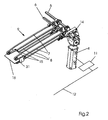
- the transport device is shown for itself.
- the drive motor 4 drives by means of a mechanical transmission 14, the drive shafts 5 and 6 and the belts 7, 8 of the transport device.
- the control unit 11 and the connection for exchanging data and / or control signals 12 can be seen.
- the products are, from a further, not shown transport system coming out of the delivery of a stapler, braked at the leading edge stops 15.
- the leading edge stops 15 are provided only in a first cutting position for the leading edge trimming.
- the transport of the product 16 to the second cutting position by the transport device 9 takes place without further alignment.
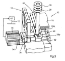
- Fig. 3 the alignment device 30 is shown.
- the orientation of the product 16 is performed by the bumper 31, which detects the product 16 side.
- it may be provided to provide an alignment device 30 according to the invention on only one side of the product 16.
- a preferred embodiment has an alignment device 30 on both sides of the product 16. These can be controlled separately or jointly by a controller 42.
- the bumper 31 is clamped by a clamp 32 on guide pins 33a, 33b.
- the guide pins 33a, 33b are connected at one end to a tab 34, to which the drive 35 for movement initiation is also connected.
- a connecting piece 36 of the drive 35 is fixed to the housing 13 of the cutting device 50.
- the drive 35 is activated via signals from the alignment control 42 and thus controlled independently of the movement of the knife lifting device 2.
- the bumper 31 In order to laterally align the product 16 in the device 50, the bumper 31 is moved in an oscillating manner in a cyclic manner. By loosening the clamping screw 38, the clamping between the bumper 31 and the terminal 32 and the guide pins 33a, 33b is released and by turning the adjusting screw 39, the terminal 32 can be moved depending on the format on the guide pins 33a, 33b. This sets different section widths.
- the drive 35 In the illustrated embodiment of the alignment device 30, the drive 35 is a pneumatic cylinder. Other variants for initiating the thrust movement on the guide pins 33a, 33b are about solenoids or linear drives.
- the leading edge trimming of a product 16 is performed simultaneously in a first cutting position and in a second cutting position of the head orohnberough a second product 16.
- the other components of the device according to the invention 50 thus sometimes transport the second product 16 out of the device 50 from the second cutting position, transport the first product 16 from the first cutting position to the second cutting position and bring a new product 16 into the first cutting position.
- the transport device 9 must bring the product up to the leading edge stops 15 and also ensure a lateral alignment of the product before trimming.
- the conveyor belts 7, 8 of the transport device 9 are also operated during the lateral pushing movement by the alignment device 30, so that the product 16 is driven against the leading edge stop 15 until it is completely aligned.
- the machine cycle of the device 50 is increased, it is not enough to increase all other movements of the device to the same extent. Rather, the transport time of the product 16 within the device 50 must not fall below a minimum transport time, since otherwise the gentle and safe transport of the product 16 can not be guaranteed.
- the time of the start of the pushing movement and its Duration are adjusted so that the same time for the transport of the product 16 within the cutter 50.
- the device has been described above in particular in connection with the three-sided trimming of brochures which are produced in a saddle stitcher. However, it is readily conceivable to use the device for three-sided trimming of other products.
Landscapes
- Life Sciences & Earth Sciences (AREA)
- Forests & Forestry (AREA)
- Engineering & Computer Science (AREA)
- Mechanical Engineering (AREA)
- Folding Of Thin Sheet-Like Materials, Special Discharging Devices, And Others (AREA)
- Lining Or Joining Of Plastics Or The Like (AREA)
- Apparatuses And Processes For Manufacturing Resistors (AREA)
- Automobile Manufacture Line, Endless Track Vehicle, Trailer (AREA)
- Nonmetal Cutting Devices (AREA)
- Details Of Cutting Devices (AREA)
Abstract
Description
Die Erfindung betrifft eine Vorrichtung zum gleichzeitigen dreiseitigen Beschnitt von Produkten, insbesondere Broschuren gemäß dem Oberbegriff des Anspruchs 1. Eine derartige Vorrichtung wird in
Bei der Herstellung von Broschuren werden an Sammelheftern die zusammengetragenen und gehefteten Produkte in einer Vorrichtung zum dreiseitigen Beschnitt, etwa einem Trimmer geschnitten. Dies erfolgt in den Schneidstationen für den Vorderschnitt und den Kopfbeschnitt bzw. Fußbeschnitt durch ein bewegtes Obermesser gegen ein feststehendes Untermesser. Der Beschnitt der Broschur stellt dabei einen besonders wichtigen Schritt dar, da hierdurch die Falzbogen seitlich geöffnet werden und das äußere Erscheinungsbild der Broschur maßgeblich beeinflusst wird. Dazu ist es wichtig, dass die Broschuren positionsgenau geschnitten werden. Daher wird vor dem Schnitt das Produkt gegen Vorderkantenanschläge transportiert und seitlich ausgerichtet, um die Abschnittsbreite für den Kopfbeschnitt bzw. Fußbeschnitt exakt einzustellen. Aus dem Stand der Technik ist es bekannt, dass der Mechanismus für die seitliche Ausrichtung dabei durch die Hubbewegung des Obermesserträgers angetrieben wird und somit direkt an den Bewegungsablauf der Schneidbewegung gekoppelt ist. Ein derartiger Trimmer ist bekannt. Nachteilig am Stand der Technik ist, dass bei derartigen Schneideinrichtungen die Geschwindigkeit der Broschur in der Schneideeinrichtung begrenzt ist, da sonst das Abprallen der Broschur beim Vorderkantenanschlag ein sauberes Ausrichten und damit einen sauberen Schnitt verhindert.In booklet making, saddle stitchers cut the collected and stapled products in a three-sided trimming device such as a trimmer. This is done in the cutting stations for the front cut and the Kopfbeschnitt or Fußbeschnitt by a moving upper blade against a fixed lower blade. The trimming of the brochure is a particularly important step, as it opens the folded sheets sideways and significantly influences the appearance of the brochure. For this it is important that the brochures are cut to the exact position. Therefore, before cutting, the product is transported against leading edge stops and laterally aligned to precisely set the section width for the head trimming. It is known from the prior art that the mechanism for the lateral alignment is driven by the lifting movement of the upper knife carrier and is thus directly coupled to the movement sequence of the cutting movement. Such a trimmer is known. A disadvantage of the prior art is that in such cutting devices, the speed of the brochure is limited in the cutting device, otherwise the bounce of the brochure at the leading edge stop prevents a clean alignment and thus a clean cut.
Daher ist es Aufgabe der Erfindung, eine Schneideeinrichtung zu schaffen, die eine größere Produktivität erlaubt. Diese Aufgabe wird mit einer Vorrichtung zum dreiseitigen Beschnitt mit den kennzeichnenden Merkmalen von Anspruch 1 gelöst. Weitere Merkmale ergeben sich aus den Unteransprüchen.Therefore, it is an object of the invention to provide a cutting device that allows greater productivity. This object is achieved with a device for three-sided trimming with the characterizing features of
Dementsprechend umfasst eine derartige Vorrichtung zum dreiseitigen Beschnitt Mittel zum Einleiten und / oder Beenden der Stoßbewegung der Ausrichtungseinrichtung, derart, dass der Zeitpunkt des Einleitens und / oder die Stoßdauer der Stoßbewegung innerhalb der Taktdauer der Vorrichtung unabhängig von der Hubbewegung der Hubeinrichtung ist. Durch diese Entkopplung der Schneidbewegung von der Stoßbewegung kann die insgesamt für den dreiseitigen Beschnitt des Produktes zur Verfügung stehende Zeit besser genutzt werden. Zudem ist eine Anpassung beispielsweise der Stoßdauer auf unterschiedliche Produkteigenschaften, wie dessen Gewicht oder Abmessungen, möglich.Accordingly, such a device for three-sided trimming comprises means for initiating and / or terminating the thrust movement of the alignment device such that the time of initiation and / or the burst duration of the thrust movement within the cycle time of the device is independent of the lifting movement of the lifting device. This decoupling of the cutting movement from the impact movement makes it possible to make better use of the time available overall for the three-sided trimming of the product. In addition, an adaptation, for example, the duration of impact on different product properties, such as its weight or dimensions possible.
In der Vorrichtung ist der Ausrichtungseinrichtung ein separater Antrieb zugeordnet, wobei die Vorrichtung eine Steuerung umfasst, die den Antrieb der Ausrichtungseinrichtung unabhängig von der der Hubbewegung der Hubeinrichtung ansteuert. Dadurch entfällt das aufwendige Ableiten der Stoßbewegung von der Hubbewegung der Hubeinrichtung, etwa durch ein mechanisches Kurvengetriebe. Außerdem können in der Steuerung für den Antrieb der Ausrichtungseinrichtung produktabhängig optimierte elektronische Steuerungskurven hinterlegt werden.In the apparatus, the alignment device is associated with a separate drive, wherein the device comprises a controller which controls the drive of the alignment device independently of the lifting movement of the lifting device. This eliminates the costly deriving the shock movement of the lifting movement of the lifting device, such as a mechanical cam gear. In addition, product-dependent optimized electronic control curves can be stored in the control for driving the alignment device.
In der Vorrichtung umfasst die Vorrichtung eine Transporteinrichtung, die das Produkt in eine erste Schneidposition und von einer ersten Schneidposition in eine zweite Schneidposition innerhalb einer Transportdauer bringt. Wie bereits erwähnt, hat diese Transportdauer ein Minimum, das nicht unterschritten werden sollte, da andernfalls durch die entsprechend gesteigerte Transportgeschwindigkeit das Abbremsen des Produkts in der Schneidposition erschwert ist. Entsprechend ist vorteilhafterweise die Steuerung der Ausrichtungseinrichtung derart ausgelegt, dass diese den Zeitpunkt des Einleitens und /oder Beendens der Stoßbewegung der Ausrichtungseinrichtung derart bestimmt, dass sich bei einer Verkürzung der Taktdauer der Hubbewegung der Hubeinrichtung die Transportdauer des Produkts im Wesentlichen nicht erhöht. Dabei wird durch Verlegung des Zeitpunkts des Einleitens und eine Verkürzung der Stoßbewegungsdauer innerhalb des Maschinentaktes auch bei einer erhöhten Produktivität der Schneideinrichtung, also einer verkürzten Taktdauer, gewährleistet, dass der Transport des Produktes mit gleicher Qualität stattfindet. Auf diese Weise ist es möglich, bei gleich bleibender Transportdauer den Maschinentakt beispielsweise von 10.000 Takten pro Stunde auf 14.000 oder 16.000 Takte pro Stunde anzuheben.In the apparatus, the apparatus comprises a transport device which brings the product into a first cutting position and from a first cutting position to a second cutting position within a transport time. As already mentioned, this transport time has a minimum, which should not be undershot, because otherwise the slowing down of the product in the cutting position is made more difficult by the correspondingly increased transport speed. Accordingly, advantageously, the control of the alignment device is designed such that it determines the time of initiation and / or termination of the thrust movement of the alignment device such that substantially does not increase the transport time of the product at a shortening of the stroke duration of the lifting movement of the lifting device. In this case, by laying the timing of the initiation and a shortening of the shock movement time within the machine cycle even at an increased productivity of the cutting device, ie a shorter cycle time, ensures that the transport of the product takes place with the same quality. In this way, it is possible for the same duration of transport For example, to increase the machine cycle from 10,000 cycles per hour to 14,000 or 16,000 cycles per hour.
In der Vorrichtung ist im Bereich einer ersten Schneidposition der Vorrichtung wenigstens zeitweise ein Vorderkantenanschlag für das Produkt angeordnet. Vorteilhafterweise ist dieser Vorderkantenanschlag in der übrigen Zeit aus der Transportebene abgeschwenkt, um die übrigen Bewegungsabläufe in der Vorrichtung nicht zu behindern.In the device, a leading edge stop for the product is at least temporarily arranged in the region of a first cutting position of the device. Advantageously, this leading edge stop is swung out of the transport plane in the remaining time in order not to hinder the other movements in the device.
In einer weiteren vorteilhaften Ausführungsform der erfindungsgemäßen Vorrichtung findet die Stoßbewegung der Stoßeinrichtung während der Transportbewegung der Transporteinrichtung statt. Insbesondere wird vorteilhafterweise die Transporteinrichtung derart betrieben, dass das Produkt vor Erreichen des Vorderkantenanschlags bereits etwas abgebremst wird und die Transporteinrichtung mit verminderter Geschwindigkeit während der seitlichen Stoßbewegung das Produkt weiter gegen den Vorderkantenanschlag treibt.In a further advantageous embodiment of the device according to the invention, the thrust movement of the pusher takes place during the transport movement of the transport device. In particular, the transport device is advantageously operated such that the product is already braked somewhat before reaching the leading edge stop and the transport device continues to drive the product against the leading edge stop at a reduced speed during the lateral pushing movement.
Bevorzugte Ausführungsformen der erfindungsgemäßen Vorrichtung werden im folgenden unter Bezugnahme auf die Zeichnungen im Einzelnen näher beschrieben.Preferred embodiments of the device according to the invention are described in detail below with reference to the drawings.
- Fig. 1Fig. 1
- eine Ansicht der Schneideinrichtung zum Randbeschneiden von Produkten,a view of the cutting device for edge trimming products,
- Fig. 2Fig. 2
- eine detaillierte Ansicht des Transportsystems unda detailed view of the transport system and
- Fig. 3Fig. 3
- eine detaillierte Ansicht der Ausrichtungseinrichtunga detailed view of the alignment device
Ein repräsentatives Beispiel für eine Schneideinrichtung zum dreiseitigen Beschnitt von Produkten wird in
In der
In
Um das Produkt 16 in der Vorrichtung 50 seitlich auszurichten, wird die Stoßleiste 31 taktweise oszillierend bewegt. Durch Lösen der Klemmschraube 38 wird die Klemmung zwischen der Stoßleiste 31 bzw. der Klemme 32 und den Führungsbolzen 33a, 33b aufgehoben und durch Drehen der Verstellschraube 39 kann die Klemme 32 auf den Führungsbolzen 33a, 33b formatabhängig verschoben werden. Dadurch werden unterschiedliche Abschnittsbreiten eingestellt. In der gezeigten Ausführungsform der Ausrichtungseinrichtung 30 handelt es sich bei dem Antrieb 35 um einen Pneumatikzylinder. Weitere Varianten zur Einleitung der Stoßbewegung auf die Führungsbolzen 33a, 33b sind etwa Hubmagnete oder Linearantriebe.In order to laterally align the
Im laufenden Betrieb der erfindungsgemäßen Vorrichtung 50 wird gleichzeitig in einer ersten Schneidposition der Vorderkantenbeschnitt eines Produktes 16 durchgeführt sowie in einer zweiten Schneidposition der Kopf- bzw. Fußbeschnitt eines zweiten Produktes 16. Innerhalb des Taktes der Hubbewegung der Messerhubeinrichtung 2 müssen die übrigen Komponenten der erfindungsgemäßen Vorrichtung 50 also mitunter das zweite Produkt 16, aus der zweiten Schneidposition aus der Vorrichtung 50 heraustransportieren, das erste Produkt 16 aus der ersten Schneidposition in die zweite Schneidposition transportieren und ein neues Produkt 16 in die erste Schneidposition bringen. Dazu muss die Transporteinrichtung 9 das Produkt bis zu den Vorderkantenanschlägen 15 bringen und ebenfalls eine seitliche Ausrichtung des Produktes vor dem Beschnitt gewährleisten. Dazu werden die Transportbänder 7, 8 der Transporteinrichtung 9 auch während der seitlichen Stoßbewegung durch die Ausrichtungseinrichtung 30 betrieben, so dass das Produkt 16 gegen den Vorderkantenanschlag 15 getrieben wird bis es vollständig ausgerichtet ist. Wird nun der Maschinentakt der Vorrichtung 50 erhöht, ist es nicht damit getan, alle übrigen Bewegungen der Vorrichtung in gleichem Maße zu erhöhen. Vielmehr darf die Transportdauer des Produkts 16 innerhalb der Vorrichtung 50 eine Mindesttransportdauer nicht unterschreiten, da sonst der schonende und sichere Transport des Produkts 16 nicht gewährleistet werden kann. Um dennoch die Schneideinrichtung 50 mit höheren Produktionsgeschwindigkeiten und damit mit einem kürzeren Takt betreiben zu können, kann nun dank des gesonderten Antriebs der Stoßbewegung und der zugeordneten Ausrichtungssteuerung 42 der Zeitpunkt des Beginns der Stoßbewegung sowie dessen Dauer derart angepasst werden, dass für den Transport des Produkts 16 innerhalb der Schneideinrichtung 50 gleich viel Zeit bleibt.During operation of the
Die Vorrichtung wurde vorgehend insbesondere im Zusammenhang mit dem dreiseitigen Beschnitt von Broschuren, die in einem Sammelhefter erzeugt werden, beschrieben. Es ist aber ohne weiteres denkbar, die Vorrichtung auch zum dreiseitigen Beschneiden von anderen Produkten zu verwenden.The device has been described above in particular in connection with the three-sided trimming of brochures which are produced in a saddle stitcher. However, it is readily conceivable to use the device for three-sided trimming of other products.
Claims (4)
- A device for simultaneous trimming of products (16) in several cutting positions comprising: a blade lifting device (2) configured to be operable in a lifting movement, wherein the lifting movement defines a machine cycle of the device (50); wherein at least blades (3) for head trimming, foot trimming and front edge trimming of the products (16) can be mounted on the lifting device (2); and wherein the device is provided with an alignment device (30) at least movable on one side for performing a pushing movement against the product (16), for bringing the product (16) into a cutting position; and wherein the device comprises a conveying device (9) which brings the product (16) into a first cutting position and from a first cutting position into a second cutting position within a transport period; wherein the device for the lateral alignment (30) of the product (16) is disposed in the first cutting position; wherein front edge stops (15) are only provided in the first cutting position for front edge trimming; and wherein the device for lateral alignment (30) has a pushing strip (31), which is moved in a cyclically oscillating manner in order to align the product (16), characterized in that the device comprises means (35, 42) for initiating and / or ending the pushing movement of the alignment device (30), such that the time of initiating the movement and / or the duration of the pushing movement lies within the cycle time of the device (50) independently of the lifting movement of the blade lifting device (2); wherein the alignment device (30) is assigned a separate drive (35).
- The device according to claim 1, characterized in that the device (50) comprises a control device (42) configured to activate the drive (35) of the alignment device (30) substantially independently of the lifting movement of the blade lifting device (2).
- The device according to claim 1, characterized in that the control device (42) defines the time of initiating and / or ending the pushing movement of the alignment device (30) such that the transport period of the product (16) is substantially not increased when the cycle duration of the lifting movement of the blade lifting device (2) is shortened.
- The device according to claim 1, characterized in that the pushing movement of the alignment device (30) is timed to take place during the transport movement of the transport device (9).
Applications Claiming Priority (1)
| Application Number | Priority Date | Filing Date | Title |
|---|---|---|---|
| DE102005033614A DE102005033614A1 (en) | 2005-07-19 | 2005-07-19 | Device for three-sided trimming of products |
Publications (2)
| Publication Number | Publication Date |
|---|---|
| EP1745895A1 EP1745895A1 (en) | 2007-01-24 |
| EP1745895B1 true EP1745895B1 (en) | 2010-04-21 |
Family
ID=37102496
Family Applications (1)
| Application Number | Title | Priority Date | Filing Date |
|---|---|---|---|
| EP06116691A Active EP1745895B1 (en) | 2005-07-19 | 2006-07-06 | Apparatus for three-side trimming |
Country Status (3)
| Country | Link |
|---|---|
| EP (1) | EP1745895B1 (en) |
| AT (1) | ATE464986T1 (en) |
| DE (2) | DE102005033614A1 (en) |
Families Citing this family (3)
| Publication number | Priority date | Publication date | Assignee | Title |
|---|---|---|---|---|
| DE102013002410A1 (en) * | 2013-02-11 | 2014-08-14 | Heidelberger Druckmaschinen Ag | Device for three-sided trimming of products |
| CN104440982A (en) * | 2014-12-12 | 2015-03-25 | 柳州市志菱汽车配件有限公司 | Automatic cutting device |
| CN104526727A (en) * | 2014-12-12 | 2015-04-22 | 柳州市志菱汽车配件有限公司 | Control system |
Family Cites Families (9)
| Publication number | Priority date | Publication date | Assignee | Title |
|---|---|---|---|---|
| BE548293A (en) * | 1956-05-09 | 1900-01-01 | ||
| DE6947166U (en) * | 1969-12-05 | 1970-06-04 | Wohlenberg Kg H | DEVICE FOR THE PRECISE ANGLE SYSTEM OF PAPER STACKS IN PAPER CUTTING MACHINES. |
| USRE28840E (en) * | 1971-02-10 | 1976-06-08 | Rockwell International Corporation | Feed, transport and delivery mechanism for book trimmers and the like |
| DE3302946C2 (en) * | 1982-02-05 | 1986-12-04 | H. Wohlenberg KG GmbH & Co, 3000 Hannover | Three-knife cutting machine |
| US4922773A (en) * | 1988-01-05 | 1990-05-08 | Itoh Iron Works Co., Ltd. | Three-side cutting apparatus |
| DE19516047C2 (en) * | 1995-05-04 | 1997-04-30 | Wohlenberg Vertriebs Und Servi | Triple cutter |
| DE10021449A1 (en) * | 2000-05-03 | 2001-11-08 | Heidelberger Druckmasch Ag | Cutting device |
| EP1182018B1 (en) * | 2000-08-07 | 2005-10-26 | Grapha Holding AG | Apparatus to automatic cut the open sides of bound printed matters |
| DE10204296A1 (en) * | 2002-02-02 | 2003-08-14 | Kolbus Gmbh & Co Kg | Device for three-sided trimming of printed products |
-
2005
- 2005-07-19 DE DE102005033614A patent/DE102005033614A1/en not_active Withdrawn
-
2006
- 2006-07-06 EP EP06116691A patent/EP1745895B1/en active Active
- 2006-07-06 AT AT06116691T patent/ATE464986T1/en active
- 2006-07-06 DE DE502006006758T patent/DE502006006758D1/en active Active
Also Published As
| Publication number | Publication date |
|---|---|
| DE502006006758D1 (en) | 2010-06-02 |
| ATE464986T1 (en) | 2010-05-15 |
| DE102005033614A1 (en) | 2007-01-25 |
| EP1745895A1 (en) | 2007-01-24 |
Similar Documents
| Publication | Publication Date | Title |
|---|---|---|
| EP1759820B1 (en) | Trilateral trimmer | |
| EP1832399B2 (en) | Method and device for automatically cutting printed products | |
| EP1842633A1 (en) | Cutting apparatus having a blowing device for waste removal | |
| DE102007032604A1 (en) | Perfect binder | |
| EP2377688A2 (en) | Device for producing adhesively bound products | |
| EP3141398B1 (en) | Method and machine for producing glue-bound printed products | |
| EP2189293A2 (en) | Gathering and stitching unit | |
| EP1745895B1 (en) | Apparatus for three-side trimming | |
| EP1152310B1 (en) | Cutting device | |
| EP2641709B1 (en) | Cutting device | |
| DE102006013171A1 (en) | Stapling device with a stapling head for processing eyelet staples | |
| EP2361785A1 (en) | Method of binding printed products with a binding machine and a binding machine for carrying out the method. | |
| EP1419898B1 (en) | Stapler used in the collation of printed articles to form printed products | |
| EP2764963B1 (en) | Device for cutting products on three sides | |
| EP1334938A1 (en) | Device for producing bound printed products | |
| EP2641708B1 (en) | Cutting device | |
| EP2119569B1 (en) | Gathering wire stitcher with variable chain distribution | |
| DE10055582A1 (en) | Device and method for cutting a web | |
| EP2774772B1 (en) | Method for fastening and crimping method with only one crimping head | |
| EP2119568B1 (en) | Wire stitcher | |
| EP2336062A1 (en) | Method and device for processing printed products composed of multiple paper layers and perforating blade | |
| DE102021110007A1 (en) | Apparatus and method for inserting bookmarks | |
| EP1574355A2 (en) | Gang-stitcher with one stitching station | |
| EP2939844B1 (en) | Stitcher for stitching a folding sheet assembly in motion and method for same | |
| EP0963281B1 (en) | Method and device for cutting cuttable material from paper materials or paperlike stackable materials |
Legal Events
| Date | Code | Title | Description |
|---|---|---|---|
| PUAI | Public reference made under article 153(3) epc to a published international application that has entered the european phase |
Free format text: ORIGINAL CODE: 0009012 |
|
| AK | Designated contracting states |
Kind code of ref document: A1 Designated state(s): AT BE BG CH CY CZ DE DK EE ES FI FR GB GR HU IE IS IT LI LT LU LV MC NL PL PT RO SE SI SK TR |
|
| AX | Request for extension of the european patent |
Extension state: AL BA HR MK YU |
|
| 17P | Request for examination filed |
Effective date: 20070724 |
|
| AKX | Designation fees paid |
Designated state(s): AT BE BG CH CY CZ DE DK EE ES FI FR GB GR HU IE IS IT LI LT LU LV MC NL PL PT RO SE SI SK TR |
|
| 17Q | First examination report despatched |
Effective date: 20070920 |
|
| GRAP | Despatch of communication of intention to grant a patent |
Free format text: ORIGINAL CODE: EPIDOSNIGR1 |
|
| GRAS | Grant fee paid |
Free format text: ORIGINAL CODE: EPIDOSNIGR3 |
|
| GRAA | (expected) grant |
Free format text: ORIGINAL CODE: 0009210 |
|
| AK | Designated contracting states |
Kind code of ref document: B1 Designated state(s): AT BE BG CH CY CZ DE DK EE ES FI FR GB GR HU IE IS IT LI LT LU LV MC NL PL PT RO SE SI SK TR |
|
| REG | Reference to a national code |
Ref country code: GB Ref legal event code: FG4D Free format text: NOT ENGLISH |
|
| REG | Reference to a national code |
Ref country code: CH Ref legal event code: EP |
|
| REG | Reference to a national code |
Ref country code: IE Ref legal event code: FG4D Free format text: LANGUAGE OF EP DOCUMENT: GERMAN |
|
| REF | Corresponds to: |
Ref document number: 502006006758 Country of ref document: DE Date of ref document: 20100602 Kind code of ref document: P |
|
| REG | Reference to a national code |
Ref country code: NL Ref legal event code: VDEP Effective date: 20100421 |
|
| LTIE | Lt: invalidation of european patent or patent extension |
Effective date: 20100421 |
|
| PG25 | Lapsed in a contracting state [announced via postgrant information from national office to epo] |
Ref country code: ES Free format text: LAPSE BECAUSE OF FAILURE TO SUBMIT A TRANSLATION OF THE DESCRIPTION OR TO PAY THE FEE WITHIN THE PRESCRIBED TIME-LIMIT Effective date: 20100801 Ref country code: LT Free format text: LAPSE BECAUSE OF FAILURE TO SUBMIT A TRANSLATION OF THE DESCRIPTION OR TO PAY THE FEE WITHIN THE PRESCRIBED TIME-LIMIT Effective date: 20100421 Ref country code: NL Free format text: LAPSE BECAUSE OF FAILURE TO SUBMIT A TRANSLATION OF THE DESCRIPTION OR TO PAY THE FEE WITHIN THE PRESCRIBED TIME-LIMIT Effective date: 20100421 Ref country code: SE Free format text: LAPSE BECAUSE OF FAILURE TO SUBMIT A TRANSLATION OF THE DESCRIPTION OR TO PAY THE FEE WITHIN THE PRESCRIBED TIME-LIMIT Effective date: 20100421 |
|
| REG | Reference to a national code |
Ref country code: IE Ref legal event code: FD4D |
|
| PG25 | Lapsed in a contracting state [announced via postgrant information from national office to epo] |
Ref country code: FI Free format text: LAPSE BECAUSE OF FAILURE TO SUBMIT A TRANSLATION OF THE DESCRIPTION OR TO PAY THE FEE WITHIN THE PRESCRIBED TIME-LIMIT Effective date: 20100421 Ref country code: IS Free format text: LAPSE BECAUSE OF FAILURE TO SUBMIT A TRANSLATION OF THE DESCRIPTION OR TO PAY THE FEE WITHIN THE PRESCRIBED TIME-LIMIT Effective date: 20100821 Ref country code: LV Free format text: LAPSE BECAUSE OF FAILURE TO SUBMIT A TRANSLATION OF THE DESCRIPTION OR TO PAY THE FEE WITHIN THE PRESCRIBED TIME-LIMIT Effective date: 20100421 Ref country code: SI Free format text: LAPSE BECAUSE OF FAILURE TO SUBMIT A TRANSLATION OF THE DESCRIPTION OR TO PAY THE FEE WITHIN THE PRESCRIBED TIME-LIMIT Effective date: 20100421 |
|
| PG25 | Lapsed in a contracting state [announced via postgrant information from national office to epo] |
Ref country code: PL Free format text: LAPSE BECAUSE OF FAILURE TO SUBMIT A TRANSLATION OF THE DESCRIPTION OR TO PAY THE FEE WITHIN THE PRESCRIBED TIME-LIMIT Effective date: 20100421 Ref country code: GR Free format text: LAPSE BECAUSE OF FAILURE TO SUBMIT A TRANSLATION OF THE DESCRIPTION OR TO PAY THE FEE WITHIN THE PRESCRIBED TIME-LIMIT Effective date: 20100722 Ref country code: CY Free format text: LAPSE BECAUSE OF FAILURE TO SUBMIT A TRANSLATION OF THE DESCRIPTION OR TO PAY THE FEE WITHIN THE PRESCRIBED TIME-LIMIT Effective date: 20100505 |
|
| BERE | Be: lapsed |
Owner name: HEIDELBERGER DRUCKMASCHINEN A.G. Effective date: 20100731 |
|
| PG25 | Lapsed in a contracting state [announced via postgrant information from national office to epo] |
Ref country code: IE Free format text: LAPSE BECAUSE OF FAILURE TO SUBMIT A TRANSLATION OF THE DESCRIPTION OR TO PAY THE FEE WITHIN THE PRESCRIBED TIME-LIMIT Effective date: 20100421 Ref country code: DK Free format text: LAPSE BECAUSE OF FAILURE TO SUBMIT A TRANSLATION OF THE DESCRIPTION OR TO PAY THE FEE WITHIN THE PRESCRIBED TIME-LIMIT Effective date: 20100421 Ref country code: EE Free format text: LAPSE BECAUSE OF FAILURE TO SUBMIT A TRANSLATION OF THE DESCRIPTION OR TO PAY THE FEE WITHIN THE PRESCRIBED TIME-LIMIT Effective date: 20100421 Ref country code: PT Free format text: LAPSE BECAUSE OF FAILURE TO SUBMIT A TRANSLATION OF THE DESCRIPTION OR TO PAY THE FEE WITHIN THE PRESCRIBED TIME-LIMIT Effective date: 20100823 |
|
| PLBE | No opposition filed within time limit |
Free format text: ORIGINAL CODE: 0009261 |
|
| STAA | Information on the status of an ep patent application or granted ep patent |
Free format text: STATUS: NO OPPOSITION FILED WITHIN TIME LIMIT |
|
| PG25 | Lapsed in a contracting state [announced via postgrant information from national office to epo] |
Ref country code: RO Free format text: LAPSE BECAUSE OF FAILURE TO SUBMIT A TRANSLATION OF THE DESCRIPTION OR TO PAY THE FEE WITHIN THE PRESCRIBED TIME-LIMIT Effective date: 20100421 Ref country code: MC Free format text: LAPSE BECAUSE OF NON-PAYMENT OF DUE FEES Effective date: 20100731 Ref country code: CZ Free format text: LAPSE BECAUSE OF FAILURE TO SUBMIT A TRANSLATION OF THE DESCRIPTION OR TO PAY THE FEE WITHIN THE PRESCRIBED TIME-LIMIT Effective date: 20100421 Ref country code: SK Free format text: LAPSE BECAUSE OF FAILURE TO SUBMIT A TRANSLATION OF THE DESCRIPTION OR TO PAY THE FEE WITHIN THE PRESCRIBED TIME-LIMIT Effective date: 20100421 |
|
| 26N | No opposition filed |
Effective date: 20110124 |
|
| REG | Reference to a national code |
Ref country code: FR Ref legal event code: ST Effective date: 20110331 |
|
| PG25 | Lapsed in a contracting state [announced via postgrant information from national office to epo] |
Ref country code: FR Free format text: LAPSE BECAUSE OF NON-PAYMENT OF DUE FEES Effective date: 20100802 |
|
| PG25 | Lapsed in a contracting state [announced via postgrant information from national office to epo] |
Ref country code: BE Free format text: LAPSE BECAUSE OF NON-PAYMENT OF DUE FEES Effective date: 20100731 |
|
| PG25 | Lapsed in a contracting state [announced via postgrant information from national office to epo] |
Ref country code: BG Free format text: LAPSE BECAUSE OF FAILURE TO SUBMIT A TRANSLATION OF THE DESCRIPTION OR TO PAY THE FEE WITHIN THE PRESCRIBED TIME-LIMIT Effective date: 20100421 Ref country code: HU Free format text: LAPSE BECAUSE OF FAILURE TO SUBMIT A TRANSLATION OF THE DESCRIPTION OR TO PAY THE FEE WITHIN THE PRESCRIBED TIME-LIMIT Effective date: 20101022 Ref country code: LU Free format text: LAPSE BECAUSE OF NON-PAYMENT OF DUE FEES Effective date: 20100706 |
|
| PG25 | Lapsed in a contracting state [announced via postgrant information from national office to epo] |
Ref country code: TR Free format text: LAPSE BECAUSE OF FAILURE TO SUBMIT A TRANSLATION OF THE DESCRIPTION OR TO PAY THE FEE WITHIN THE PRESCRIBED TIME-LIMIT Effective date: 20100421 |
|
| REG | Reference to a national code |
Ref country code: AT Ref legal event code: MM01 Ref document number: 464986 Country of ref document: AT Kind code of ref document: T Effective date: 20110706 |
|
| PGFP | Annual fee paid to national office [announced via postgrant information from national office to epo] |
Ref country code: IT Payment date: 20120726 Year of fee payment: 7 |
|
| PG25 | Lapsed in a contracting state [announced via postgrant information from national office to epo] |
Ref country code: AT Free format text: LAPSE BECAUSE OF NON-PAYMENT OF DUE FEES Effective date: 20110706 |
|
| PG25 | Lapsed in a contracting state [announced via postgrant information from national office to epo] |
Ref country code: BG Free format text: LAPSE BECAUSE OF FAILURE TO SUBMIT A TRANSLATION OF THE DESCRIPTION OR TO PAY THE FEE WITHIN THE PRESCRIBED TIME-LIMIT Effective date: 20100721 |
|
| PG25 | Lapsed in a contracting state [announced via postgrant information from national office to epo] |
Ref country code: IT Free format text: LAPSE BECAUSE OF NON-PAYMENT OF DUE FEES Effective date: 20130706 |
|
| REG | Reference to a national code |
Ref country code: CH Ref legal event code: PUE Owner name: MUELLER MARTINI HOLDING AG, CH Free format text: FORMER OWNER: HEIDELBERGER DRUCKMASCHINEN AKTIENGESELLSCHAFT, DE |
|
| REG | Reference to a national code |
Ref country code: DE Ref legal event code: R081 Ref document number: 502006006758 Country of ref document: DE Owner name: MUELLER MARTINI HOLDING AG, CH Free format text: FORMER OWNER: HEIDELBERGER DRUCKMASCHINEN AG, 69115 HEIDELBERG, DE Effective date: 20141023 |
|
| REG | Reference to a national code |
Ref country code: GB Ref legal event code: 732E Free format text: REGISTERED BETWEEN 20141204 AND 20141211 |
|
| PGFP | Annual fee paid to national office [announced via postgrant information from national office to epo] |
Ref country code: GB Payment date: 20190724 Year of fee payment: 14 |
|
| GBPC | Gb: european patent ceased through non-payment of renewal fee |
Effective date: 20200706 |
|
| PG25 | Lapsed in a contracting state [announced via postgrant information from national office to epo] |
Ref country code: GB Free format text: LAPSE BECAUSE OF NON-PAYMENT OF DUE FEES Effective date: 20200706 |
|
| PGFP | Annual fee paid to national office [announced via postgrant information from national office to epo] |
Ref country code: DE Payment date: 20220728 Year of fee payment: 17 |
|
| PGFP | Annual fee paid to national office [announced via postgrant information from national office to epo] |
Ref country code: CH Payment date: 20220718 Year of fee payment: 17 |
|
| REG | Reference to a national code |
Ref country code: DE Ref legal event code: R119 Ref document number: 502006006758 Country of ref document: DE |
|
| REG | Reference to a national code |
Ref country code: CH Ref legal event code: PL |
|
| PG25 | Lapsed in a contracting state [announced via postgrant information from national office to epo] |
Ref country code: DE Free format text: LAPSE BECAUSE OF NON-PAYMENT OF DUE FEES Effective date: 20240201 Ref country code: CH Free format text: LAPSE BECAUSE OF NON-PAYMENT OF DUE FEES Effective date: 20230731 |