EP1745870A1 - Méthode de fabrication des corps de base des axes creuses - Google Patents
Méthode de fabrication des corps de base des axes creuses Download PDFInfo
- Publication number
- EP1745870A1 EP1745870A1 EP05016016A EP05016016A EP1745870A1 EP 1745870 A1 EP1745870 A1 EP 1745870A1 EP 05016016 A EP05016016 A EP 05016016A EP 05016016 A EP05016016 A EP 05016016A EP 1745870 A1 EP1745870 A1 EP 1745870A1
- Authority
- EP
- European Patent Office
- Prior art keywords
- starting material
- base body
- main body
- bore
- hollow shaft
- Prior art date
- Legal status (The legal status is an assumption and is not a legal conclusion. Google has not performed a legal analysis and makes no representation as to the accuracy of the status listed.)
- Ceased
Links
Images


Classifications
-
- B—PERFORMING OPERATIONS; TRANSPORTING
- B21—MECHANICAL METAL-WORKING WITHOUT ESSENTIALLY REMOVING MATERIAL; PUNCHING METAL
- B21H—MAKING PARTICULAR METAL OBJECTS BY ROLLING, e.g. SCREWS, WHEELS, RINGS, BARRELS, BALLS
- B21H1/00—Making articles shaped as bodies of revolution
- B21H1/18—Making articles shaped as bodies of revolution cylinders, e.g. rolled transversely cross-rolling
-
- B—PERFORMING OPERATIONS; TRANSPORTING
- B21—MECHANICAL METAL-WORKING WITHOUT ESSENTIALLY REMOVING MATERIAL; PUNCHING METAL
- B21K—MAKING FORGED OR PRESSED METAL PRODUCTS, e.g. HORSE-SHOES, RIVETS, BOLTS OR WHEELS
- B21K1/00—Making machine elements
- B21K1/06—Making machine elements axles or shafts
- B21K1/10—Making machine elements axles or shafts of cylindrical form
Definitions
- the present invention relates to a method for producing hollow shaft bodies, which comprises a first step, in which the outer surface of a cylindrical starting material is machined by forming to obtain at least a predetermined diameter transition in the longitudinal direction of a base body, and a further step, in which the base body for reshaping the outer and / or inner surface of the base body is formed incrementally to the hollow shaft main body comprises.
- a weight saving can be achieved, for example, by designing the gear shaft as a hollow shaft. This reduces the overall weight of the transmission, and thus the overall weight of a motor vehicle in which the transmission is installed, which is desirable in terms of reducing fuel consumption.
- the requirement to form a shaft as a hollow shaft may also have gear technology reasons.
- a shaft-in-shaft or through drive it is desirable to make this shaft partially or totally hollow.
- the trend of an increasing number of waves in a motor vehicle transmission leads to an increase in the overall weight of a transmission, so that in the context of resource conservation, such as material and fuel economy and environmental compatibility (emission reduction), measures must be taken to reduce the weight of the individual transmission shafts.
- the hollow shaft is manufactured by combining two known methods.
- a solid starting material is formed by swaging to a basic body.
- the main body can be formed by cross wedge rolling.
- the Hollow shaft a bore or inner bore made in the longitudinal direction of the body machined.
- This hole is formed by means of a deep hole drilling as a through hole or blind hole.
- a deep hole drilling method indicates a machining in which the ratio between the bore diameter to be drilled and the length to be drilled is 1: 6 or greater.
- the deep hole drilling requires special machines and tools (deep hole drills) and thus brings increased production costs. Further, with the methods described above it is not possible to have undercuts in the bore, i. along the inner surface of the hollow shaft produced. Finally, this method has the disadvantage that the requirement of conserving resources due to the machining is not met.
- a method according to the preamble of claim 1 is known.
- the outer peripheral surface of the starting material is contoured by cold extrusion, and then a hole is formed in the solid material.
- the basic body is shaped by rotary swaging or cold extrusion. Since this known method has a machining step, a considerable portion of the material used is wasted. Furthermore, the extrusion results in a circumferentially anisotropic material flow, which is disadvantageous in waves. In addition, several forming stages are required for large cross-sectional changes and / or complicated workpieces.
- the hydroforming process is based in principle on the fact that a hollow part widened by hydrostatic internal pressure, simultaneously compressed in the axial and / or radial direction and finally expanded by an even higher pressure against the tool contours of a tool.
- this method is not preferable in view of the quality of the obtained hollow shaft main body.
- due to accumulation of material wrinkles on the hollow shaft body arise.
- the hydroforming process is not suitable in view of the necessary residual wall thickness of a gearbox hollow shaft.
- the object of the invention is to overcome the disadvantages of the known methods.
- a further object of the invention is to provide a method with which hollow shafts with relatively large diameter jumps can be produced on the outside diameter in material accumulations typical of pinion shaft gearboxes.
- the outer surface of a cylindrical starting material is processed by cross wedge rolling such that at least one predetermined diameter transition in the longitudinal direction of a base body is obtained.
- the cylindrical stock is placed between two profiled rolls or flats to radially reshape the starting material, i. to achieve diameter changes or jumps at predetermined portions of the outer circumferential surface.
- An advantage of this method is that a good material economy is achieved because it hardly comes to material waste in this non-cutting production process.
- the cross wedge rolling has the advantage of low cycle times. If the starting material has a bore, a mandrel is introduced into the bore before the cross wedge rolling, whereby the desired material flow is conveyed on the outer circumferential surface during the forming and the preservation of the bore is ensured. But it can also be introduced simultaneously two mandrels at the respective end of the starting material.
- the mandrels can be arranged for this purpose movable and / or stationary.
- the mandrel is, for example, cylindrical with a smooth surface but may also have a certain surface geometry and / or diameter grading, which transfers during the cross wedge rolling on the inner peripheral surface of the starting material.
- a desired surface contour is generated.
- the intermediate product produced in the first step ie the main body thus has, in particular on its outer circumferential surface, at least one predetermined desired diameter transition.
- the starting material is not limited to cylindrical starting materials having a circular cross section. Rather, starting materials with other cross-sectional shapes, such as rectangular cross-sections can be used. However, starting materials having a rotationally symmetrical cross section are to be preferred.
- the base body obtained after the first step preferably has a circular cross section with a contoured surface, ie is rotationally symmetrical.
- a base body is created in the first step, which may have a plurality of different outer diameters.
- the base body if it is already hollow, be formed with varying wall thickness.
- the shaped recesses and / or elevations can be formed, for example, as almost cylindrical sections.
- the outer and / or inner surface of the main body is converted in a further step incrementally to a hollow shaft main body.
- Incremental forming as such is a known method and refers to a forming process in which the forming is not carried out in a single tool stroke, but the body is formed in several steps.
- the method according to the invention offers the possibility of representing the predominant outer and / or inner circumferential surfaces of the hollow shaft main body by contouring.
- the hollow shaft main body present after the further step preferably only has to be post-machined, where bearing seats of the hollow shaft are designed for rolling bearings and / or tooth flanks are formed on radial projections.
- the starting material is formed during the first step by axial force introduction to form an axial bore.
- This bore may be a bore extending longitudinally of the stock or only a bore extending partially in the longitudinal direction of the stock.
- two bores can be generated by axial introduction of force at the respective end of the starting material.
- the bore is formed by inserting at least one mandrel in the longitudinal direction of the starting material and forming the starting material radially outwardly.
- the mandrel may preferably be inserted into the stock material during cross wedge rolling such that the longitudinal axes of the stock material and the at least one dome coincide, the mandrel being held stationary as the stock material rotates between the rolls.
- the mandrel or spines are inserted axially at least to a region where a diameter transition is formed on the outer surface of the starting material.
- the insertion of the mandrel and the cross wedge rolling are preferably coordinated so that the mandrel enters the area towards the end of the cross wedge rolling.
- a bore extending in the longitudinal direction of the starting material may be formed in the starting material.
- This hole can, as described above, by axial force application, ie in particular during hot forming by Pressing a thorn are formed.
- the starting material is introduced into the cross wedge rolling device and held there stationary and formed the bore by axial force application.
- the one or two axial bores having starting material is then cross wedge-rolled in the first step.
- the bore may alternatively be produced by other forming processes, such as extrusion or by machining prior to the first step.
- an axial bore may be formed in the base body subsequent to the first step. For example, by machining.
- the inner peripheral surface of the bore is reworked.
- Such post-processing is desirable for smoothing the inner peripheral surface and is performed by, for example, grinding, polishing, turning and / or the like.
- a contact surface (bore), which has been cleared of surface defects caused by deformation machining, for the at least one mandrel introduced during the incremental forming process contributes to increased quality of the hollow shaft main body.
- the main body is separated before the further step into a plurality of main body subunits and these main body subunits are each transformed in the further step to hollow shaft main bodies.
- This preferred development has the advantage that, by using a single starting material, ie a single blank, a plurality of hollow shaft main body can be produced, which leads to an increased productivity of this method.
- the separation of the main body subunits can be done by any method, however, in view of minimizing the material waste, a forming process for separating the main body into a plurality of main body subunits is preferred.
- the main body is separated during the first step by a forming process. For example, by shear rollers or ridges, which are brought into effect at the end of the cross wedge rolling in the cross wedge rolling stand, the starting material into a plurality of main body subunits be separated.
- the hollow shaft main body is formed incrementally by rotary swaging.
- the inner and outer surfaces of the body are reshaped to obtain a hollow shaft body having desired inner surface and outer surface contouring.
- a mandrel may be inserted at both ends of the body.
- only one side of the body is incrementally formed in the further step by inserting a preferably stepped dome, while the other side is freely formed on its inner circumferential surface.
- the at least one mandrel can be arranged movable or stationary. If several mandrels are used, they can be arranged differently from each other, i. a mandrel can be arranged movable and the other stationary. These can also have on their peripheral surface diameter jumps and / or continuous diameter transitions. In the case of free forms, d. H. Incremental forming without a mandrel, an increased wall thickness can be achieved in this area.
- the method variant Einstechrundkneten in which the tools are also delivered radially, can be used when undercuts are desired on the inner or outer peripheral surface. If special requirements are placed on the inner surface of the hollow shaft body, swaging is performed using a dome. In this process variant, a mandrel is introduced into the bore during the forming process and thus, for example, a high dimensional accuracy and a good surface quality is achieved.
- rotary kneading such as hot circular kneading in the further step of the method according to the invention can be used.
- the method produces a hollow-shaft main body which has a length-to-diameter ratio which is at least twice as long as the starting material.
- a relatively short non-slender starting material is formed into a long hollow shaft body.
- To determine the ratio is the lowest incrementally reshaped diameter decisive.
- multiple outer diameter jumps can be realized.
- These multiple diameter jumps are realized, for example, by projections spaced apart from one another in the longitudinal direction on the outer circumferential surface with the same or different diameters.
- the multiple diameter jumps may also be stepped, i. be realized by adjacent, stepped up or down projections.
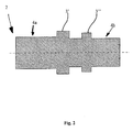
- a cylindrical starting material is converted in a first step by cross wedge rolling to a base body 2.
- the stock material is positioned between the two profiled rolls or jaws of a cross wedge rolling apparatus.
- the profiles present on these rollers, or jaws, are transferred to the starting material during the forming process.
- the base body 2 After forming by cross wedge rolling, the base body 2 thus obtained has a desired outer surface profile. That is, by the cross-sectional change by means of cross wedge rolling, the main body 2 has a contoured outer peripheral surface with predetermined diameter transitions.
- the base body 2 shown in FIG. 1 consists essentially of two cylindrical sections 4a, 4b, which form the ends of the main body 2.
- FIG. 1 Another exemplary outer surface contouring of the component obtained by cross wedge rolling is shown in FIG.
- two different elevations 3 ', 3 are formed on the outer circumferential surface of the starting material, wherein the elevation 3' has a larger radius than the elevation 3".
- This embodiment has cylinder sections 4a, 4b with different diameters.
- Gears or seats for gears or bearings can be formed on the elevations 3 ', 3 "by means of reworking
- the number of elevations 3', 3" for forming such functional surfaces on the hollow shaft can be chosen as desired.
- the embodiment shown in Figure 2 shows only a time recording of the starting material during the first step, since preferably also at least one extending in the longitudinal direction of the starting material bore is incorporated during the cross wedge rolling in the starting material.
- the starting material is reformed, for example, at temperatures known for hot working steel materials in the first step.
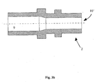
- an axial force application in the longitudinal direction of the starting material is exerted on the workpiece via a mandrel 9 or two mandrels 9a, 9b. In this way, a bore 10 with a constant diameter as shown in FIG. 3a can be generated.
- the inserted mandrel 9 may have on its peripheral surface diameter gradations and thus produce a bore 10 'as shown in FIG. 3b.
- the mandrel 9 can be guided either axially movable during cross wedge rolling or be arranged stationary.
- the exemplary embodiments according to FIGS. 3 a and 3 b show continuous bores 10, 10 'extending in the longitudinal direction of the starting material, but it is also possible to produce a blind hole 16, as shown in FIG. 3 c.
- the closed end is preferably severed before the further step.
- 3d shows a further exemplary embodiment, which has a main body with two bores 10 "which are not connected to one another. For this purpose, a mandrel is introduced into the starting material in each case at one end of the starting material.
- the exemplary embodiments described above ie the base bodies 2 according to FIGS. 3a to 3d, show the intermediate product obtained after the first method step.
- a forming method is preferable in view of the requirement of material saving.
- the production of a bore during cross wedge rolling by penetrating the at least one dome into the starting material, wherein the mandrel is introduced to a region corresponding to the contouring on the outer peripheral surface of the starting material, has the advantage that a material flow is effected radially outward This material flow contributes to a dimensionally accurate surface contouring, that is, because the material is in the range of the desired Elevations or projections is also pressed outwards against the profile of the rollers, the material adapts to the roll profiling very accurately.
- This post-processing takes place at least at that portion of the bore 10, 10 ', 10 ", 16 at which a mandrel is applied by rotary swaging in a further step for incremental deformation of the base body.
- the outer and inner circumferential surfaces 4, 6 of the base 2 are deformed.
- the deformation of the inner peripheral surface 6 results from the deformation of the outer peripheral surface 4 of the base body 2 by the forming tools. That is, the rotary kneading takes place, with respect to the base body 2, from outside to inside and the material thus flows in the radial and axial directions.
- a mandrel is introduced into the base body.
- a cylindrical mandrel is inserted into the bore 10 to provide a desired cylindrical geometry to the inner peripheral surface 6 of the body 2 during swaging.
- This one process variant of rotary kneading can be combined with the further process variant Einstechrundkneten, for example, to create undercuts.
- the hollow base body 2 has been incrementally formed by rotary swaging in the further process step, it has the desired diameter transitions on the outer circumferential surface 12 of the hollow shaft main body 8, and an inner diameter impressed by the mandrel. That is, by machining the starting material according to this embodiment of the present invention, diameter jumps can be provided on the outer diameter.
- the elevations 3 on the outer peripheral surface 12 of the hollow shaft 8 can be machined for molding, for example, gears, bearing seats, splines and rolling teeth. If desired, a heat treatment, hardening treatment and the like may follow to meet the requirements imposed on a transmission shaft.
- the second exemplary embodiment shown in FIGS. 4a and 4b is produced by first of all forming the basic body 2 'shown in FIG. 4a by means of cross-wedge rolling. This has a single survey 3 '. On the right side of the elevation 3 'in FIG. 4a, the base body 2' has a short cylinder section 4b 'with a smaller outside diameter than the cylinder section 4a' located on the left side of the elevation 3 '.
- the hollow shaft main body 8' shown in FIG. 4b is formed by kneading the left cylindrical section 4b '.
- a mandrel 18 which has four discrete cylinder sections 20a-20d, which merge into one another continuously via three cone sections 22a-22c.
- the obtained after the rotary kneading inner and outer peripheral surface of the hollow shaft main body 8 ' is shown in Fig. 4b in a solid line.
- dot-dashed lines which represent the finished contour of the finished hollow shaft.
- the ends of the hollow shaft main body 8 ' are tapped.
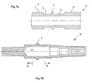
- FIGS. 5a and 5b A further embodiment is shown in FIGS. 5a and 5b in the same way as explained with reference to FIGS. 4a and 4b.
- the basic body 2 "shown in FIG. 5 a is first of all, after introduction of a dome 18", formed incrementally on the side lying to the right of the elevation 3. Thereafter, the mandrel 18 "is removed, after which the side of the intermediate product lying to the left of the elevation 3 is incrementally reshaped, whereby no mandrel is inserted, and the inner contour of the left part is thus freely formed during the forming lying region of the body 2 "is not transformed incrementally.
- the hollow shaft base body which is thus incrementally shaped under half-warm to warm conditions, is then machined to obtain the dot-dashed outline shown in FIG. 5b. This indicates the finished part.
Priority Applications (1)
| Application Number | Priority Date | Filing Date | Title |
|---|---|---|---|
| EP05016016A EP1745870A1 (fr) | 2005-07-22 | 2005-07-22 | Méthode de fabrication des corps de base des axes creuses |
Applications Claiming Priority (1)
| Application Number | Priority Date | Filing Date | Title |
|---|---|---|---|
| EP05016016A EP1745870A1 (fr) | 2005-07-22 | 2005-07-22 | Méthode de fabrication des corps de base des axes creuses |
Publications (1)
| Publication Number | Publication Date |
|---|---|
| EP1745870A1 true EP1745870A1 (fr) | 2007-01-24 |
Family
ID=34979766
Family Applications (1)
| Application Number | Title | Priority Date | Filing Date |
|---|---|---|---|
| EP05016016A Ceased EP1745870A1 (fr) | 2005-07-22 | 2005-07-22 | Méthode de fabrication des corps de base des axes creuses |
Country Status (1)
| Country | Link |
|---|---|
| EP (1) | EP1745870A1 (fr) |
Cited By (8)
| Publication number | Priority date | Publication date | Assignee | Title |
|---|---|---|---|---|
| WO2008145092A1 (fr) * | 2007-05-26 | 2008-12-04 | Neumayer Tekfor Holding Gmbh | Procédé de fabrication d'éléments de base d'arbre creux et éléments de base d'arbre creux fabriqués selon ce procédé |
| DE102008036226A1 (de) | 2008-08-02 | 2010-02-04 | Volkswagen Ag | Verfahren zur Herstellung einer Hohlwelle |
| DE102010040008A1 (de) * | 2010-08-31 | 2012-03-01 | Zf Lenksysteme Gmbh | Hohlwelle zur Kraftübertragung innerhalb eines EPS-Lenksystems mit Riemenscheibe |
| DE102012005106A1 (de) | 2012-03-14 | 2013-09-19 | Fraunhofer-Gesellschaft zur Förderung der angewandten Forschung e.V. | Verfahren zur Herstellung einer Hohlwelle und Vorrichtung hierfür |
| DE102015221842A1 (de) * | 2015-11-06 | 2017-05-11 | Volkswagen Aktiengesellschaft | Verfahren zur Herstellung einer Getriebewelle |
| CN111842771A (zh) * | 2019-04-29 | 2020-10-30 | 大众汽车有限公司 | 用于制造空心轴的方法 |
| CN113770666A (zh) * | 2021-09-16 | 2021-12-10 | 浙江百达精工股份有限公司 | 空心转轴制造方法和汽车驱动电机空心转轴 |
| EP3854517A4 (fr) * | 2019-06-18 | 2021-12-15 | Changshu Synergy Automobile Parts Co., Ltd. | Nouveau procédé de fabrication d'arbre creux |
Citations (5)
| Publication number | Priority date | Publication date | Assignee | Title |
|---|---|---|---|---|
| JPS577305A (en) * | 1980-06-13 | 1982-01-14 | Nissan Motor Co Ltd | Method and apparatus for manufacturing hollow shaft |
| EP0052077B1 (fr) | 1980-11-06 | 1985-01-16 | Colcon Anstalt | Procédé de fabrication d'un arbre creux à symétrie de révolution |
| JPS61126937A (ja) * | 1984-11-22 | 1986-06-14 | Mitsubishi Heavy Ind Ltd | 段付き軸状製品の製造方法 |
| DE19705279A1 (de) | 1997-02-12 | 1997-11-20 | Daimler Benz Ag | Verfahren zum Herstellen von Rohlingen für hohle Getriebewellen |
| DE19905038A1 (de) * | 1999-02-08 | 2000-08-17 | Fraunhofer Ges Forschung | Dorneinrichtung, Querwalzvorrichtung und Verfahren zur Herstellung quergewalzter, zumindest partiell hohler Körper |
-
2005
- 2005-07-22 EP EP05016016A patent/EP1745870A1/fr not_active Ceased
Patent Citations (5)
| Publication number | Priority date | Publication date | Assignee | Title |
|---|---|---|---|---|
| JPS577305A (en) * | 1980-06-13 | 1982-01-14 | Nissan Motor Co Ltd | Method and apparatus for manufacturing hollow shaft |
| EP0052077B1 (fr) | 1980-11-06 | 1985-01-16 | Colcon Anstalt | Procédé de fabrication d'un arbre creux à symétrie de révolution |
| JPS61126937A (ja) * | 1984-11-22 | 1986-06-14 | Mitsubishi Heavy Ind Ltd | 段付き軸状製品の製造方法 |
| DE19705279A1 (de) | 1997-02-12 | 1997-11-20 | Daimler Benz Ag | Verfahren zum Herstellen von Rohlingen für hohle Getriebewellen |
| DE19905038A1 (de) * | 1999-02-08 | 2000-08-17 | Fraunhofer Ges Forschung | Dorneinrichtung, Querwalzvorrichtung und Verfahren zur Herstellung quergewalzter, zumindest partiell hohler Körper |
Non-Patent Citations (3)
| Title |
|---|
| KAPITONOV I M: "IMPROVING ROLLING OF MACHINE PART BLANKS", STEEL IN TRANSLATION, INSTITUTE OF MATERIALS, LONDON, GB, vol. 28, no. 7, 1998, pages 46 - 49, XP000890769, ISSN: 0967-0912 * |
| PATENT ABSTRACTS OF JAPAN vol. 006, no. 065 (M - 124) 24 April 1982 (1982-04-24) * |
| PATENT ABSTRACTS OF JAPAN vol. 010, no. 320 (M - 530) 30 October 1986 (1986-10-30) * |
Cited By (11)
| Publication number | Priority date | Publication date | Assignee | Title |
|---|---|---|---|---|
| WO2008145092A1 (fr) * | 2007-05-26 | 2008-12-04 | Neumayer Tekfor Holding Gmbh | Procédé de fabrication d'éléments de base d'arbre creux et éléments de base d'arbre creux fabriqués selon ce procédé |
| DE102008023696A1 (de) | 2007-05-26 | 2008-12-24 | Neumayer Tekfor Holding Gmbh | Verfahren zur Herstellung von Hohlwellengrundkörpern sowie nach dem Verfahren hergestellte Hohlwellengrundkörper |
| DE102008036226A1 (de) | 2008-08-02 | 2010-02-04 | Volkswagen Ag | Verfahren zur Herstellung einer Hohlwelle |
| DE102008036226B4 (de) | 2008-08-02 | 2018-12-27 | Volkswagen Ag | Verfahren zur Herstellung einer Hohlwelle |
| DE102010040008A1 (de) * | 2010-08-31 | 2012-03-01 | Zf Lenksysteme Gmbh | Hohlwelle zur Kraftübertragung innerhalb eines EPS-Lenksystems mit Riemenscheibe |
| DE102012005106A1 (de) | 2012-03-14 | 2013-09-19 | Fraunhofer-Gesellschaft zur Förderung der angewandten Forschung e.V. | Verfahren zur Herstellung einer Hohlwelle und Vorrichtung hierfür |
| DE102012005106B4 (de) * | 2012-03-14 | 2017-02-23 | Fraunhofer-Gesellschaft zur Förderung der angewandten Forschung e.V. | Verfahren zur Herstellung einer Hohlwelle und Vorrichtung hierfür |
| DE102015221842A1 (de) * | 2015-11-06 | 2017-05-11 | Volkswagen Aktiengesellschaft | Verfahren zur Herstellung einer Getriebewelle |
| CN111842771A (zh) * | 2019-04-29 | 2020-10-30 | 大众汽车有限公司 | 用于制造空心轴的方法 |
| EP3854517A4 (fr) * | 2019-06-18 | 2021-12-15 | Changshu Synergy Automobile Parts Co., Ltd. | Nouveau procédé de fabrication d'arbre creux |
| CN113770666A (zh) * | 2021-09-16 | 2021-12-10 | 浙江百达精工股份有限公司 | 空心转轴制造方法和汽车驱动电机空心转轴 |
Similar Documents
| Publication | Publication Date | Title |
|---|---|---|
| DE112006000619B4 (de) | Verfahren zum Herstellen einer Lenkungszahnstange | |
| DE102008036226B4 (de) | Verfahren zur Herstellung einer Hohlwelle | |
| EP1702695B1 (fr) | Méthode de production d'une partie de transition dans un profilé creux | |
| DE102006006029B3 (de) | Verfahren zum Herstellen von nicht-rotationssymmetrischen Ringen und Nockenring | |
| EP1745870A1 (fr) | Méthode de fabrication des corps de base des axes creuses | |
| DE102012005106B4 (de) | Verfahren zur Herstellung einer Hohlwelle und Vorrichtung hierfür | |
| DE102009045251A1 (de) | Formen von Vorformlingen und Teilen davon | |
| DE102013226929A1 (de) | Verfahren und Vorrichtung zur Herstellung einer Hohlwelle durch Radialumformen sowie hiermit hergestellte Hohlwelle | |
| DE3336581A1 (de) | Mehrfach-keilriemenscheibe und verfahren zu ihrer herstellung | |
| EP1502011A1 (fr) | Came monobloc, son procede de fabrication, et assemblage d'un arbre de commande ou arbre a came | |
| DE10337929A1 (de) | Verfahren zur Herstellung von einteiligen Hohlkörpern mit profilierten Endbereichen, Hohlkörper und Verwendung der Hohlkörper | |
| DE102007002228A1 (de) | Verfahren und Vorrichtung zur Herstellung von innenprofilierten Rohren | |
| WO2008145092A1 (fr) | Procédé de fabrication d'éléments de base d'arbre creux et éléments de base d'arbre creux fabriqués selon ce procédé | |
| EP1551577B1 (fr) | Procede et dispositif pour produire une jante pour pneumatiques | |
| DE102005036419B4 (de) | Vorrichtung zur Herstellung ausgebauchter Hohlprofile, insbesondere von Gasgeneratorgehäusen für Airbageinrichtungen | |
| WO2008074560A2 (fr) | Procédé de fabrication d'un anneau de synchronisation d'un dispositif de synchronisation | |
| EP1024913B1 (fr) | Procede et dispositif pour produire un arbre a partir d'un element tubulaire | |
| WO2008003305A1 (fr) | Procédé de production d'une pièce à symétrie de rotation et pièce ainsi obtenue | |
| EP1611973B1 (fr) | Procédé de formage de tubes et de fabrication d'arbres creux | |
| DE102016107240A1 (de) | Verfahren zur Herstellung einer Schiebemuffe für eine Schaltgetriebe-Synchronbaugruppe sowie mittels des Verfahrens hergestellte Schiebemuffe | |
| DE19727599B4 (de) | Verfahren zur Herstellung von Metallrädern | |
| WO2020119849A1 (fr) | Procédé pour la préparation d'une piste de roulement à billes au niveau d'une pièce ainsi qu'écrou fileté à billes comportant une piste de roulement à billes préparée de cette façon | |
| DE102016115798B3 (de) | Verfahren und Einrichtung zur Herstellung von Kolbenringen | |
| DE10148451C2 (de) | Verfahren zur Herstellung eines Hohlkörpers und Vorform | |
| DE102021002526B3 (de) | Verfahren zur Herstellung einer Hohlwelle, eine damit hergestellte Hohlwelle sowie ein diesbezügliches Formgebungswerkzeug |
Legal Events
| Date | Code | Title | Description |
|---|---|---|---|
| PUAI | Public reference made under article 153(3) epc to a published international application that has entered the european phase |
Free format text: ORIGINAL CODE: 0009012 |
|
| AK | Designated contracting states |
Kind code of ref document: A1 Designated state(s): AT BE BG CH CY CZ DE DK EE ES FI FR GB GR HU IE IS IT LI LT LU LV MC NL PL PT RO SE SI SK TR |
|
| AX | Request for extension of the european patent |
Extension state: AL BA HR MK YU |
|
| 17P | Request for examination filed |
Effective date: 20070723 |
|
| AKX | Designation fees paid |
Designated state(s): AT BE BG CH CY CZ DE DK EE ES FI FR GB GR HU IE IS IT LI LT LU LV MC NL PL PT RO SE SI SK TR |
|
| 17Q | First examination report despatched |
Effective date: 20071213 |
|
| STAA | Information on the status of an ep patent application or granted ep patent |
Free format text: STATUS: THE APPLICATION HAS BEEN REFUSED |
|
| 18R | Application refused |
Effective date: 20081103 |