EP1744082A1 - Actuator, especially for a motor vehicle - Google Patents
Actuator, especially for a motor vehicle Download PDFInfo
- Publication number
- EP1744082A1 EP1744082A1 EP05015463A EP05015463A EP1744082A1 EP 1744082 A1 EP1744082 A1 EP 1744082A1 EP 05015463 A EP05015463 A EP 05015463A EP 05015463 A EP05015463 A EP 05015463A EP 1744082 A1 EP1744082 A1 EP 1744082A1
- Authority
- EP
- European Patent Office
- Prior art keywords
- bearing
- housing
- bearing housing
- actuator according
- actuator
- Prior art date
- Legal status (The legal status is an assumption and is not a legal conclusion. Google has not performed a legal analysis and makes no representation as to the accuracy of the status listed.)
- Granted
Links
Images


Classifications
-
- F—MECHANICAL ENGINEERING; LIGHTING; HEATING; WEAPONS; BLASTING
- F16—ENGINEERING ELEMENTS AND UNITS; GENERAL MEASURES FOR PRODUCING AND MAINTAINING EFFECTIVE FUNCTIONING OF MACHINES OR INSTALLATIONS; THERMAL INSULATION IN GENERAL
- F16H—GEARING
- F16H57/00—General details of gearing
- F16H57/02—Gearboxes; Mounting gearing therein
- F16H57/021—Shaft support structures, e.g. partition walls, bearing eyes, casing walls or covers with bearings
-
- F—MECHANICAL ENGINEERING; LIGHTING; HEATING; WEAPONS; BLASTING
- F16—ENGINEERING ELEMENTS AND UNITS; GENERAL MEASURES FOR PRODUCING AND MAINTAINING EFFECTIVE FUNCTIONING OF MACHINES OR INSTALLATIONS; THERMAL INSULATION IN GENERAL
- F16C—SHAFTS; FLEXIBLE SHAFTS; ELEMENTS OR CRANKSHAFT MECHANISMS; ROTARY BODIES OTHER THAN GEARING ELEMENTS; BEARINGS
- F16C23/00—Bearings for exclusively rotary movement adjustable for aligning or positioning
- F16C23/02—Sliding-contact bearings
- F16C23/04—Sliding-contact bearings self-adjusting
-
- F—MECHANICAL ENGINEERING; LIGHTING; HEATING; WEAPONS; BLASTING
- F16—ENGINEERING ELEMENTS AND UNITS; GENERAL MEASURES FOR PRODUCING AND MAINTAINING EFFECTIVE FUNCTIONING OF MACHINES OR INSTALLATIONS; THERMAL INSULATION IN GENERAL
- F16H—GEARING
- F16H57/00—General details of gearing
- F16H57/02—Gearboxes; Mounting gearing therein
- F16H57/039—Gearboxes for accommodating worm gears
-
- F—MECHANICAL ENGINEERING; LIGHTING; HEATING; WEAPONS; BLASTING
- F16—ENGINEERING ELEMENTS AND UNITS; GENERAL MEASURES FOR PRODUCING AND MAINTAINING EFFECTIVE FUNCTIONING OF MACHINES OR INSTALLATIONS; THERMAL INSULATION IN GENERAL
- F16H—GEARING
- F16H1/00—Toothed gearings for conveying rotary motion
- F16H1/02—Toothed gearings for conveying rotary motion without gears having orbital motion
- F16H1/04—Toothed gearings for conveying rotary motion without gears having orbital motion involving only two intermeshing members
- F16H1/12—Toothed gearings for conveying rotary motion without gears having orbital motion involving only two intermeshing members with non-parallel axes
- F16H1/16—Toothed gearings for conveying rotary motion without gears having orbital motion involving only two intermeshing members with non-parallel axes comprising worm and worm-wheel
-
- F—MECHANICAL ENGINEERING; LIGHTING; HEATING; WEAPONS; BLASTING
- F16—ENGINEERING ELEMENTS AND UNITS; GENERAL MEASURES FOR PRODUCING AND MAINTAINING EFFECTIVE FUNCTIONING OF MACHINES OR INSTALLATIONS; THERMAL INSULATION IN GENERAL
- F16H—GEARING
- F16H57/00—General details of gearing
- F16H57/02—Gearboxes; Mounting gearing therein
- F16H57/021—Shaft support structures, e.g. partition walls, bearing eyes, casing walls or covers with bearings
- F16H2057/0213—Support of worm gear shafts
-
- Y—GENERAL TAGGING OF NEW TECHNOLOGICAL DEVELOPMENTS; GENERAL TAGGING OF CROSS-SECTIONAL TECHNOLOGIES SPANNING OVER SEVERAL SECTIONS OF THE IPC; TECHNICAL SUBJECTS COVERED BY FORMER USPC CROSS-REFERENCE ART COLLECTIONS [XRACs] AND DIGESTS
- Y10—TECHNICAL SUBJECTS COVERED BY FORMER USPC
- Y10T—TECHNICAL SUBJECTS COVERED BY FORMER US CLASSIFICATION
- Y10T74/00—Machine element or mechanism
- Y10T74/18—Mechanical movements
- Y10T74/18568—Reciprocating or oscillating to or from alternating rotary
- Y10T74/18792—Reciprocating or oscillating to or from alternating rotary including worm
-
- Y—GENERAL TAGGING OF NEW TECHNOLOGICAL DEVELOPMENTS; GENERAL TAGGING OF CROSS-SECTIONAL TECHNOLOGIES SPANNING OVER SEVERAL SECTIONS OF THE IPC; TECHNICAL SUBJECTS COVERED BY FORMER USPC CROSS-REFERENCE ART COLLECTIONS [XRACs] AND DIGESTS
- Y10—TECHNICAL SUBJECTS COVERED BY FORMER USPC
- Y10T—TECHNICAL SUBJECTS COVERED BY FORMER US CLASSIFICATION
- Y10T74/00—Machine element or mechanism
- Y10T74/19—Gearing
- Y10T74/19642—Directly cooperating gears
- Y10T74/19698—Spiral
- Y10T74/19828—Worm
-
- Y—GENERAL TAGGING OF NEW TECHNOLOGICAL DEVELOPMENTS; GENERAL TAGGING OF CROSS-SECTIONAL TECHNOLOGIES SPANNING OVER SEVERAL SECTIONS OF THE IPC; TECHNICAL SUBJECTS COVERED BY FORMER USPC CROSS-REFERENCE ART COLLECTIONS [XRACs] AND DIGESTS
- Y10—TECHNICAL SUBJECTS COVERED BY FORMER USPC
- Y10T—TECHNICAL SUBJECTS COVERED BY FORMER US CLASSIFICATION
- Y10T74/00—Machine element or mechanism
- Y10T74/21—Elements
- Y10T74/2186—Gear casings
Definitions
- the invention relates to an actuator with a gear unit and a motor unit.
- the gear unit has a gear housing and the motor unit a motor housing, an inner rotor with a drive shaft and in particular a cylindrical bearing housing on the drive side.
- the bearing housing protrudes into an opening of the transmission housing together with a bearing and the drive shaft guided therein.
- the invention also relates to a use of the actuator in a motor vehicle.
- Actuators such as power window drives or actuators to operate the sunroof, are already known. They have a gear unit and a motor unit.
- the gear unit has a worm wheel and a gear shaft realized as a worm shaft.
- the motor unit consists of a motor housing, a brush housing and an internal rotor.
- the rotor is designed as a so-called rotor package with a variety of attached to the motor shaft slats.
- the gear shaft and the motor shaft can also be made in one piece as a common drive shaft.
- the motor housing is flanged to the gear housing.
- a mostly cylindrical extension of the brush housing projects with the drive shaft and the worm shaft located at the free end of the drive shaft into a corresponding opening of the gear housing.
- the extension of the brush housing serves as a holder for a bearing in which the drive shaft is guided.
- the cylindrical extension can also be formed as a separate bearing housing or alternatively form a common brush and bearing housing with the brush housing.
- An actuator in which a motor housing is flanged to a transmission housing.
- the motor housing protrudes partly into a gear housing opening, wherein the protruding part encloses a spherical bearing, in which a motor shaft is guided.
- the opposite to the transmission and accommodated in the cylindrical bearing housing bearing serves as a compensation element to compensate for manufacturing tolerances in the assembly of the actuator.
- the bearing is displaced axially to some extent in its holder. If the bearing is a spherical outside surface which, within certain limits, can move in a corresponding spherical shell of the bearing support, it is also possible to compensate for deflections and radial offsets of the drive shaft. So that the bearing remains fixed after assembly in its position, a bias is applied to this.
- a common problem is that the bearing introduced into the gearbox housing opening with the cylindrical bearing housing becomes loose after a certain period of operation and, in the case of a dome, can rotate in its bearing shell.
- the reason for this are settlement processes, which are subject to plastics during a permanent load. This reduces a still existing in the new state preload in such a way that over time, the bearing or the cap begins to dissolve in the bearing bracket. This leads to wear of the bearing or the dome and thus premature failure of the actuator.
- the noise increases during actuation of the actuator.
- the object of the invention is to provide a simplified actuator, which allows a permanent fixation of a bearing.
- a biasing force is advantageously effected, which permanently fixes the bearing over the intended operating time of the actuator.
- the biasing force in turn causes an advantageously permanent frictional engagement between the outer periphery of the bearing and the bearing shell opposite this.
- gaps as stress-free areas form areas into which a bias reserve can build up, which permanently acts on the bearing.
- Another advantage is that the life of such an actuator is increased.
- a biasing force can be built up by means of the clamping points, which acts on the bearing via the bearing housing.
- the biasing force acts preferably at least circumferentially in the region of the bearing. This has the advantage that a uniform biasing force acts on the bearing from all sides.
- each a circumferential biasing force in a respective axial end region of the bearing can be built up.
- a centering force is exerted on the bearing in an advantageous manner. Any laterally acting on the bearing biasing forces, which could possibly lead to tilting of the bearing are avoided in this way.
- the bearing is particularly well axially fixed by the centering force and in the case of a dome as a bearing against rotation. The bearing remains clamped, so to speak, between the two peripherally applied preload forces.
- the inner cross section of the gearbox housing opening in the region of the bearing remains substantially the same.
- the inner cross section is circular.
- surveys are provided as terminal points.
- the biasing force is generated according to the invention.
- the elevations may be located selectively or linearly on the outer circumference of the bearing housing.
- the surveys may e.g. also have the form of lenses or bars with a maximum height of 1 mm.
- the elevations preferably form at least one bead, which runs on the outer circumference of the bearing housing, so that the biasing force advantageously acts uniformly on the outer circumference of the bearing.
- the elevations or the at least one bead lie in a respective axial end region of the bearing, so that the respective circumferential preload force can advantageously act centering on the bearing.
- the cross section of the bearing housing is reduced axially in at least one stage in the region of the bearing.
- the inner cross section of the transmission housing opening decreases in a corresponding manner axially in at least one stage.
- the gear housing opening tapers axially in the direction of the worm shaft.
- the insertion of the bearing housing into the gear housing opening is also facilitated during assembly of the actuator. After inserting the bearing housing, in particular shortly before reaching the final insertion position, the corresponding stages jam against each other to terminal points according to the invention.
- the step height is less than 1 mm, in particular, this is in a range of 0.1 to 0.5 mm.
- the cross section of the bearing housing decreases in the axial end region of the bearing in each case a step.
- the inner cross section of the transmission housing opening is reduced axially in two stages.
- corresponding steps in the inner cross-section of the gear housing opening and on the outer circumference of the bearing housing jam together to form the clamping points according to the invention.
- the resulting circumferential preload forces have an advantageous effect centering on the bearing.
- the steps can be chamfered so that they jam in a catch.
- the steps are chamfered in a range of 30 ° to 60 °.
- the bearing is a dome with a spherical outer surface for both embodiments.
- This outer surface can move within certain limits in a corresponding spherical shell of the bearing housing. A caused by manufacturing and / or assembly tolerances bending and a radial offset of the drive shaft to a small extent are compensated advantageous by the possible compensation rotation of the calotte.
- the dome is preferably made of a sintered material.
- the porous structure of the sintered material can absorb a lubricant, in particular a lubricating oil, for lubricating the drive shaft guided inside the dome.
- the bearing housing is part of a combined brush and bearing housing.
- plug contacts are provided which are guided electrically in the interior of the brush housing to the brush in the commutator of the rotor.
- the bearing housing or the combined brush and bearing housing with the elevations, beads or steps is a plastic injection molded part.
- Possible plastics are e.g. Polypropylene or polyamide.
- a particularly suitable type of plastic is PA 6.6.
- the plastic has a certain elasticity, which is particularly suitable for building up a biasing force in response to a mechanical deformation.
- the elastic mechanical deformation is caused by resulting bending moments during insertion into the opening of the transmission housing.
- a complex component such as e.g. manufacture the combined brush and bearing housing with the integrated engine mount, in one production step.
- An actuator according to the invention can be advantageously used in a motor vehicle, since in particular there a high number of compact actuators, such as. to lift the window or to open and close a sliding roof, is needed.
- the gear unit 2 has a gear housing 12 in which a worm wheel 4 and a worm shaft 4 engaging in the worm 4 are housed.
- the motor unit 8 consists of a motor housing 11, a rotor 9 accommodated therein with a drive shaft 5 and a bearing housing 18 on the drive side of the motor unit 8.
- the worm shaft 3 sits on the free end of the drive shaft 5 and is driven by the motor unit 8 is and is housed in part in the motor housing 11.
- the drive shaft 5 is guided on the motor side in a bearing 2 opposite the gear unit 2 and in a motor end bearing 10.
- the drive shaft 5 is made in one piece.
- a two-piece version of the drive shaft 5 in the motor shaft and gear shaft with an intermediate link is also conceivable.
- the brush and bearing housing 17 is composed of a brush housing 19 with electrical terminals and carbon brushes housed therein for the commutator of the rotor 9 and a bearing housing 18 the camp 6 housed therein together.
- the bearing housing 18 is designed substantially cylindrical, so that it can be easily inserted into a corresponding opening 7 of the gear housing 12.
- elevations 14, 15 are mounted as clamping points on the outer side or on the outer circumference of the bearing housing 18, which are formed according to an embodiment of the actuator as circumferential beads.
- the elevations 14, 15 or the circumferential beads are arranged according to a further embodiment, that viewed in the axial direction depending a bead 14, 15 is arranged in the end region of the bearing 6.
- the bearing 6 is a dome in the example of FIG 2 according to another embodiment of the invention.
- FIG. 3 shows a perspective schematic view of FIG. 2 in an elevational view along the drive shaft 5 of the actuator 1.
- the cap 6 with its spherical outer surface into the bearing housing 18 can be seen.
- FIG 4 shows an enlarged view of a projecting into a gear housing opening 7 bearing housing 18 according to FIG 1.
- a part of the brush housing 17 of a combined brush and bearing housing 11 is shown.
- the corresponding cylindrical bearing housing 18 with the bearing 6 can be seen.
- the drawn Outer diameter A of the bearing housing 18 is slightly smaller than the inner diameter D of the transmission housing opening 7. This is effected by the spacing of the outer periphery of the bearing housing 18 by means of the elevations 14, 15 or the annular beads according to the invention.
- the prestressing forces F1, F2 which build up between the two beads 14, 15 act centered towards the center of the bearing 6.
- the stress-free gap 29 forming between the beads advantageously forms an area for establishing a bias reserve. In this area, then, the bearing housing 18, so to speak, "bulge in”.
- FIG 4 already shows the execution of the bearing 6 as a calotte, in which the drive shaft 5 is guided.
- R denotes the maximum radius of the spherical outer surface.
- the reference numeral 13 the contour of the opposite bearing shell is marked.
- the dome 6 is chamfered on its inner side 19, so that compensating twists through the dome 6 are possible to some extent.
- the gear housing opening 7 has a taper 16 in the axial direction to the worm shaft 3, which serves to center the worm shaft 3 during insertion of the drive shaft 5 in the gear housing opening 7.
- FIG 5 shows a sectional drawing of an exemplary alternative solution for building up a bias voltage F1, F2 by means of steps 21-24 and before reaching a final insertion position of the bearing housing 28 in the gear housing opening 27.
- both the bearing housing side stages 23, 24 and the corresponding gear housing-side steps 21, 22 already bevelled.
- the angle is between 30 and 60 °, in the example of FIG 5 in about 45 °.
- D1 the distance to an opening-side further taper and one end of the bearing housing 28 is located.
- the present FIG 5 also shows that the bearing housing 6 in this insertion position is still relatively loosely inserted in the gear housing opening 27. This is also shown by the enlarged gap for understanding between the cap 6 and the surrounding bearing shell of the bearing housing 28th
- FIG. 6 shows a sectional drawing according to FIG. 5 after reaching the final insertion position of the bearing housing 28 in the gearbox housing opening 27.
- this can be seen from the fact that the distance D2 between the opening-side further taper and the end of the bearing housing 28 is slightly reduced has, such as in a range of 0.5 mm to 2 mm.
- the mutually corresponding steps 21, 23 and 22, 24 are clamped so latching that in the overlapping areas, the bias of the invention F1, F2 is constructed.
- FIG. 6 shows that the gap between the dome surface and the opposite bearing shell still present in FIG has now disappeared.
- the calotte 6 is now permanently fixed in position.
- gaps 30, 31 form as stress-free areas, which serve as areas for building up a bias reserve.
Landscapes
- Engineering & Computer Science (AREA)
- General Engineering & Computer Science (AREA)
- Mechanical Engineering (AREA)
- Mounting Of Bearings Or Others (AREA)
- Connection Of Motors, Electrical Generators, Mechanical Devices, And The Like (AREA)
- General Details Of Gearings (AREA)
Abstract
Description
Die Erfindung betrifft einen Stellantrieb mit einer Getriebeeinheit und einer Motoreinheit. Die Getriebeeinheit weist ein Getriebegehäuse und die Motoreinheit ein Motorgehäuse, einen innenliegenden Läufer mit einer Antriebswelle sowie insbesondere ein zylinderförmiges Lagergehäuse auf der Antriebsseite auf. Das Lagergehäuse ragt zusammen mit einem Lager und der darin geführten Antriebswelle in eine Öffnung des Getriebegehäuses hinein. Die Erfindung betrifft zudem eine Verwendung des Stellantriebs in einem Kraftfahrzeug.The invention relates to an actuator with a gear unit and a motor unit. The gear unit has a gear housing and the motor unit a motor housing, an inner rotor with a drive shaft and in particular a cylindrical bearing housing on the drive side. The bearing housing protrudes into an opening of the transmission housing together with a bearing and the drive shaft guided therein. The invention also relates to a use of the actuator in a motor vehicle.
Stellantriebe, beispielsweise Fensterheber-Antriebe oder Antriebe zur Betätigung des Schiebedaches, sind bereits bekannt. Sie weisen eine Getriebeeinheit und eine Motoreinheit auf. Die Getriebeeinheit weist ein Schneckenrad und eine als Schneckenwelle realisierte Getriebewelle auf. Die Motoreinheit besteht aus einem Motorgehäuse, einem Bürstengehäuse und einem innenliegenden Läufer. Der Läufer ist dabei als sogenanntes Läuferpaket mit einer Vielzahl von auf der Motorwelle befestigten Lamellen ausgebildet. Die Getriebewelle und die Motorwelle können auch als gemeinsame Antriebswelle einteilig ausgeführt sein. Beim Zusammenbau des Stellantriebs wird das Motorgehäuse an das Getriebegehäuse angeflanscht. Ein zumeist zylinderförmiger Fortsatz des Bürstengehäuses ragt mit der Antriebswelle und der am freien Ende der Antriebswelle befindlichen Schneckenwelle in eine entsprechende Öffnung des Getriebegehäuses hinein. Der Fortsatz des Bürstengehäuses dient als Halterung für ein Lager, in welchem die Antriebswelle geführt wird. Der zylinderförmige Fortsatz kann auch als separates Lagergehäuse ausgebildet sein oder alternativ mit dem Bürstengehäuse ein gemeinsames Bürsten- und Lagergehäuse bilden.Actuators, such as power window drives or actuators to operate the sunroof, are already known. They have a gear unit and a motor unit. The gear unit has a worm wheel and a gear shaft realized as a worm shaft. The motor unit consists of a motor housing, a brush housing and an internal rotor. The rotor is designed as a so-called rotor package with a variety of attached to the motor shaft slats. The gear shaft and the motor shaft can also be made in one piece as a common drive shaft. When assembling the actuator, the motor housing is flanged to the gear housing. A mostly cylindrical extension of the brush housing projects with the drive shaft and the worm shaft located at the free end of the drive shaft into a corresponding opening of the gear housing. The extension of the brush housing serves as a holder for a bearing in which the drive shaft is guided. The cylindrical extension can also be formed as a separate bearing housing or alternatively form a common brush and bearing housing with the brush housing.
Aus der
Das dem Getriebe gegenüberliegende und im zylinderförmigen Lagergehäuse untergebrachte Lager dient als Ausgleichselement, um Fertigungstoleranzen beim Zusammenbau des Stellantriebs auszugleichen. Das Lager ist dabei in gewissem Maße axial in seiner Halterung verschiebbar. Ist das Lager eine Kalotte mit kugelförmiger Außenfläche, die sich in gewissen Grenzen in einer dazu korrespondierenden kugelförmigen Schale der Lagerhalterung bewegen kann, so können auch Verbiegungen und radiale Versätze der Antriebswelle ausgeglichen werden. Damit das Lager nach dem Zusammenbau in seiner Lage fixiert bleibt, wird eine Vorspannung auf dieses aufgebracht.The opposite to the transmission and accommodated in the cylindrical bearing housing bearing serves as a compensation element to compensate for manufacturing tolerances in the assembly of the actuator. The bearing is displaced axially to some extent in its holder. If the bearing is a spherical outside surface which, within certain limits, can move in a corresponding spherical shell of the bearing support, it is also possible to compensate for deflections and radial offsets of the drive shaft. So that the bearing remains fixed after assembly in its position, a bias is applied to this.
Ein häufiges Problem ist es, dass das mit dem zylindrischen Lagergehäuse in die Getriebegehäuseöffnung eingeführte Lager nach einiger Betriebszeit lose wird und im Falle einer Kalotte sich diese in ihrer Lagerschale verdrehen kann. Ursache hierfür sind Setzungsprozesse, denen Kunststoffen bei einer dauerhaften Belastung unterliegen. Dadurch verringert sich eine im Neuzustand noch vorhandene Vorspannung derart, dass sich im Laufe der Zeit das Lager bzw. die Kalotte in der Lagerhalterung zu lösen beginnt. Dies führt zu einem Verschleiß des Lagers bzw. der Kalotte und somit zu einem vorzeitigen Ausfall des Stellantriebs. Zudem nimmt die Geräuschentwicklung bei einer Betätigung des Stellantriebs zu.A common problem is that the bearing introduced into the gearbox housing opening with the cylindrical bearing housing becomes loose after a certain period of operation and, in the case of a dome, can rotate in its bearing shell. The reason for this are settlement processes, which are subject to plastics during a permanent load. This reduces a still existing in the new state preload in such a way that over time, the bearing or the cap begins to dissolve in the bearing bracket. This leads to wear of the bearing or the dome and thus premature failure of the actuator. In addition, the noise increases during actuation of the actuator.
Zur Lösung des Problems ist es bekannt, eine sogenannte Klemmbrille aus Federstahl einzusetzen, welche eine Anpresskraft auf das Lager bzw. auf die kugelförmige Außenfläche der Kalotte ausübt. Dadurch wird eine dauerhafte Reibkraft zwischen dem Getriebegehäuse und dem Lagergehäuse ausgeübt, so dass eine Verdrehsicherung und eine axiale Sicherung des Lagers erreicht werden. Nachteilig an dieser Lösung sind der erhöhte Teileaufwand und der Montageaufwand.To solve the problem, it is known to use a so-called clamping glasses made of spring steel, which exerts a contact pressure on the bearing or on the spherical outer surface of the dome. As a result, a permanent frictional force between the gear housing and the bearing housing is exerted, so that a rotation and an axial securing of the bearing be achieved. A disadvantage of this solution are the increased parts costs and installation costs.
Die Aufgabe der Erfindung besteht darin, einen vereinfachten Stellantrieb anzugeben, welcher eine dauerhafte Fixierung eines Lagers ermöglicht.The object of the invention is to provide a simplified actuator, which allows a permanent fixation of a bearing.
Diese Aufgabe wird durch einen Stellantrieb mit den im Anspruch 1 angegebenen Merkmalen gelöst. Vorteilhafte Ausgestaltungen und Weiterbildungen der Erfindung ergeben sich aus den abhängigen Ansprüchen 2 bis 14. In Anspruch 15 ist eine vorteilhafte Verwendung des Stellantriebs in einem Kraftfahrzeug angegeben.This object is achieved by an actuator with the features specified in claim 1. Advantageous embodiments and further developments of the invention will become apparent from the
Mittels der Klemmstellen wird vorteilhaft eine Vorspannkraft bewirkt, die dauerhaft das Lager über die vorgesehene Betriebsdauer des Stellantriebs fixiert. Die Vorspannkraft bewirkt ihrerseits einen vorteilhaft dauerhaften Reibschluss zwischen dem Außenumfang des Lagers und der dieser gegenüberliegenden Lagerschale. Insbesondere bilden Spalte als spannungsfreie Stellen Bereiche aus, in den sich eine Vorspannungreserve aufbauen kann, die dauerhaft auf das Lager wirkt.By means of the clamping points a biasing force is advantageously effected, which permanently fixes the bearing over the intended operating time of the actuator. The biasing force in turn causes an advantageously permanent frictional engagement between the outer periphery of the bearing and the bearing shell opposite this. In particular, gaps as stress-free areas form areas into which a bias reserve can build up, which permanently acts on the bearing.
Ein weiterer Vorteil ist, dass die Lebensdauer eines solchen Stellantriebs erhöht wird.Another advantage is that the life of such an actuator is increased.
Weiterhin verringert sich in vorteilhafter Weise die Zunahme der Geräuschentwicklung eines solchen Stellantriebs über die Lebensdauer.Furthermore, the increase in the noise development of such an actuator over the service life is advantageously reduced.
In einer Ausführungsform ist mittels der Klemmstellen eine Vorspannkraft aufbaubar, die über das Lagergehäuse auf das Lager wirkt. Die Vorspannkraft wirkt dabei vorzugsweise im Bereich des Lagers zumindest umlaufend. Damit ist der Vorteil verbunden, dass von allen Seiten eine gleichmäßige Vorspannkraft auf das Lager einwirkt.In one embodiment, a biasing force can be built up by means of the clamping points, which acts on the bearing via the bearing housing. The biasing force acts preferably at least circumferentially in the region of the bearing. This has the advantage that a uniform biasing force acts on the bearing from all sides.
In einer bevorzugten Ausführungsform ist mittels der Klemmstellen je eine umlaufende Vorspannkraft in einem jeweiligen axialen Endbereich des Lagers aufbaubar.In a preferred embodiment, by means of the clamping points each a circumferential biasing force in a respective axial end region of the bearing can be built up.
Durch die kräftemäßig seitliche Fassung des Lagers wird in vorteilhafter Weise eine zentrierende Kraft auf das Lager ausgeübt. Etwaige seitlich auf das Lager einwirkende Vorspannkräfte, welche unter Umständen zu Verkantungen des Lagers führen könnten, werden auf diese Weise vermieden. Zudem wird das Lager durch die zentrierende Kraft besonders gut axial und im Falle einer Kalotte als Lager gegen Verdrehungen fixiert. Das Lager bleibt sozusagen zwischen den beiden umlaufend aufgebrachten Vorspannkräften eingespannt.Due to the power moderate lateral version of the bearing, a centering force is exerted on the bearing in an advantageous manner. Any laterally acting on the bearing biasing forces, which could possibly lead to tilting of the bearing are avoided in this way. In addition, the bearing is particularly well axially fixed by the centering force and in the case of a dome as a bearing against rotation. The bearing remains clamped, so to speak, between the two peripherally applied preload forces.
In einer weiteren Ausführungsform bleibt der Innenquerschnitt der Getriebegehäuseöffnung im Bereich des Lagers im Wesentlichen gleich. Insbesondere ist dabei der Innenquerschnitt kreisförmig. Am Außenumfang des Lagergehäuses sind Erhebungen als Klemmstellen vorgesehen.In a further embodiment, the inner cross section of the gearbox housing opening in the region of the bearing remains substantially the same. In particular, the inner cross section is circular. On the outer circumference of the bearing housing surveys are provided as terminal points.
Durch die auf der Außenseite bzw. am Außenumfang des Lagergehäuses vorgesehenen Erhebungen wird gemäß der Erfindung die Vorspannkraft erzeugt. Die Erhebungen können sich dabei punktuell oder linienförmig auf dem Außenumfang des Lagergehäuses befinden. Die Erhebungen können z.B. auch die Form von Linsen oder Stege mit einer maximalen Höhe von 1 mm aufweisen. Mittels der Erhebungen wird eine Vorspannkraft über das Lagergehäuse auf den Außenumfang des dort untergebrachten Lagers bewirkt. Die Vorspannkraft bewirkt ihrerseits einen Reibschluss zwischen dem Außenumfang des Lagers und der dem Außenumfang gegenüberliegenden Lagerschale.By provided on the outside or on the outer circumference of the bearing housing surveys, the biasing force is generated according to the invention. The elevations may be located selectively or linearly on the outer circumference of the bearing housing. The surveys may e.g. also have the form of lenses or bars with a maximum height of 1 mm. By means of the elevations, a biasing force on the bearing housing on the outer circumference of the stored there bearing is effected. The biasing force in turn causes a frictional engagement between the outer circumference of the bearing and the outer periphery opposite bearing shell.
Die Erhebungen bilden vorzugsweise zumindest eine Wulst aus, welche am Außenumfang des Lagergehäuses verläuft, so dass die Vorspannkraft vorteilhaft gleichmäßig auf den Außenumfang des Lagers wirkt.The elevations preferably form at least one bead, which runs on the outer circumference of the bearing housing, so that the biasing force advantageously acts uniformly on the outer circumference of the bearing.
In einer bevorzugten Ausführungsform liegen die Erhebungen bzw. die zumindest eine Wulst in einem jeweiligen axialen Endbereich des Lagers, so dass die jeweils umlaufende Vorspannkraft vorteilhaft zentrierend auf das Lager einwirken kann.In a preferred embodiment, the elevations or the at least one bead lie in a respective axial end region of the bearing, so that the respective circumferential preload force can advantageously act centering on the bearing.
In einer alternativen Ausführungsform verringert sich im Bereich des Lagers der Querschnitt des Lagergehäuses axial in zumindest einer Stufe. Zudem verringert sich der Innenquerschnitt der Getriebegehäuseöffnung in korrespondierender Weise axial in zumindest einer Stufe. Die Getriebegehäuseöffnung verjüngt sich dabei axial in Richtung zur Schneckenwelle.In an alternative embodiment, the cross section of the bearing housing is reduced axially in at least one stage in the region of the bearing. In addition, the inner cross section of the transmission housing opening decreases in a corresponding manner axially in at least one stage. The gear housing opening tapers axially in the direction of the worm shaft.
Durch die zentrierende Wirkung der Verjüngung wird beim Zusammenbau des Stellantriebs außerdem das Einschieben des Lagergehäuses in die Getriebegehäuseöffnung erleichtert. Nach dem Einschieben des Lagergehäuses, insbesondere kurz vor Erreichen der endgültigen Einschubposition, verklemmen sich die korrespondierenden Stufen zu Klemmstellen gemäß der Erfindung gegeneinander.Due to the centering effect of the rejuvenation, the insertion of the bearing housing into the gear housing opening is also facilitated during assembly of the actuator. After inserting the bearing housing, in particular shortly before reaching the final insertion position, the corresponding stages jam against each other to terminal points according to the invention.
Damit ist der große Vorteil verbunden, dass eine dauerhafte Vorspannkraft durch die Verklemmung der jeweiligen Stufen bewirkt wird, welche ihrerseits einen vorteilhaft dauerhaften Reibschluss zwischen dem Außenumfang des Lagers und der dieser gegenüberliegenden Lagerschale bewirkt. Vorzugsweise ist die Stufenhöhe kleiner als 1 mm, insbesondere liegt diese in einem Bereich von 0,1 bis 0,5 mm.This has the great advantage that a permanent biasing force is caused by the jamming of the respective stages, which in turn causes an advantageous permanent frictional engagement between the outer periphery of the bearing and the bearing shell opposite this. Preferably, the step height is less than 1 mm, in particular, this is in a range of 0.1 to 0.5 mm.
Vorzugsweise verringert sich der Querschnitt des Lagergehäuses im axialen Endbereich des Lagers in je einer Stufe. In entsprechender Weise verringert sich der Innenquerschnitt der Getriebegehäuseöffnung axial in zwei Stufen. Dadurch verklemmen miteinander korrespondierende Stufen im Innenquerschnitt der Getriebegehäuseöffnung und am Außenumfang des Lagergehäuses zu den erfindungsgemäßen Klemmstellen. Die dabei entstehenden umlaufenden Vorspannkräfte wirken vorteilhaft zentrierend auf das Lager.Preferably, the cross section of the bearing housing decreases in the axial end region of the bearing in each case a step. In a corresponding manner, the inner cross section of the transmission housing opening is reduced axially in two stages. As a result, corresponding steps in the inner cross-section of the gear housing opening and on the outer circumference of the bearing housing jam together to form the clamping points according to the invention. The resulting circumferential preload forces have an advantageous effect centering on the bearing.
Insbesondere können die Stufen so abgeschrägt sein, dass sich diese in einer Verrastung verklemmen. Vorzugsweise sind die Stufen in diesem Fall in einem Bereich von 30° bis 60° abgeschrägt.In particular, the steps can be chamfered so that they jam in a catch. Preferably, in this case, the steps are chamfered in a range of 30 ° to 60 °.
Durch die Verrastung, die schlagartig erfolgt, wird eine besonders stabile Verklemmung bewirkt, die beim Zusammenbau des Stellantriebs zudem als Klickgeräusch akustisch wahrgenommen werden kann. Dieses Klickgeräusch kann vorteilhaft als Quittierungssignal für eine erfolgreiche Verrastung beim Zusammenbau eines Stellantriebs betrachtet werden.By locking, which takes place abruptly, a particularly stable jamming is effected, which can also be perceived acoustically as click sound when assembling the actuator. This clicking sound can be considered advantageous as an acknowledgment signal for a successful locking in the assembly of an actuator.
Vorzugsweise ist das Lager für beide Ausführungsformen eine Kalotte mit einer kugelförmigen Außenfläche. Diese Außenfläche kann sich in gewissen Grenzen in einer dazu korrespondierenden kugelförmigen Schale des Lagergehäuses bewegen. Eine durch Fertigungs- und/oder Montagetoleranzen bedingte Verbiegung sowie ein radialer Versatz der Antriebswelle in geringem Maße werden durch die mögliche Ausgleichsverdrehung der Kalotte vorteilhaft kompensiert.Preferably, the bearing is a dome with a spherical outer surface for both embodiments. This outer surface can move within certain limits in a corresponding spherical shell of the bearing housing. A caused by manufacturing and / or assembly tolerances bending and a radial offset of the drive shaft to a small extent are compensated advantageous by the possible compensation rotation of the calotte.
Die Kalotte ist vorzugsweise aus einem Sintermaterial gefertigt. Dadurch kann die poröse Struktur des Sintermaterials ein Schmiermittel, insbesondere ein Schmieröl, zur Schmierung der im Inneren der Kalotte geführten Antriebswelle aufnehmen.The dome is preferably made of a sintered material. As a result, the porous structure of the sintered material can absorb a lubricant, in particular a lubricating oil, for lubricating the drive shaft guided inside the dome.
In einer weiteren Ausführungsform ist das Lagergehäuse ein Teil eines kombinierten Bürsten- und Lagergehäuses. Auf der Außenseite des entsprechenden Bürstengehäuses sind üblicherweise Steckkontakte vorgesehen, die elektrisch im Inneren des Bürstengehäuses zu den Bürsten im Kommutatorbereich des Läufers geführt werden.In another embodiment, the bearing housing is part of a combined brush and bearing housing. On the outside of the corresponding brush housing usually plug contacts are provided which are guided electrically in the interior of the brush housing to the brush in the commutator of the rotor.
Durch ein solches kombiniertes Bürsten- und Lagergehäuse verringern sich vorteilhaft die Bauteilanzahl und die Anzahl der Montageschritte für einen Stellantrieb.By such a combined brush and bearing housing advantageously reduce the number of components and the number of assembly steps for an actuator.
In einer besonderen Ausführungsform ist das Lagergehäuse bzw. das kombinierte Bürsten- und Lagergehäuse mit den Erhebungen, Wulsten oder Stufen ein Kunststoff-Spritzgussteil. Mögliche Kunststoffe sind z.B. Polypropylen oder Polyamid. Ein besonders geeigneter Kunststofftyp ist PA 6.6.In a particular embodiment, the bearing housing or the combined brush and bearing housing with the elevations, beads or steps is a plastic injection molded part. Possible plastics are e.g. Polypropylene or polyamide. A particularly suitable type of plastic is PA 6.6.
Der Kunststoff weist eine gewisse Elastizität auf, die zum Aufbau einer Vorspannkraft als Reaktion auf eine mechanische Verformung besonders geeignet ist. Im Falle des Lagergehäuses wird die elastische mechanische Verformung durch resultierende Biegemomente beim Einführen in die Öffnung des Getriebegehäuses bewirkt.The plastic has a certain elasticity, which is particularly suitable for building up a biasing force in response to a mechanical deformation. In the case of the bearing housing, the elastic mechanical deformation is caused by resulting bending moments during insertion into the opening of the transmission housing.
Durch das Spritzgussverfahren lässt sich weiterhin vorteilhaft ein komplexes Bauteil, wie z.B. das kombinierte Bürsten-und Lagergehäuse mit dem integrierten Motorlager, in einem Fertigungsschritt herstellen.By the injection molding process, furthermore, a complex component such as e.g. manufacture the combined brush and bearing housing with the integrated engine mount, in one production step.
Ein Stellantrieb gemäß der Erfindung lässt sich vorteilhaft in einem Kraftfahrzeug verwenden, da insbesondere dort eine hohe Anzahl von kompakten Stellantrieben, wie z.B. zum Fensterheben oder zum Öffnen und Schließen eines Schiebedachs, benötigt wird.An actuator according to the invention can be advantageously used in a motor vehicle, since in particular there a high number of compact actuators, such as. to lift the window or to open and close a sliding roof, is needed.
Weitere vorteilhafte Eigenschaften der Erfindung ergeben sich aus deren beispielhafter Erläuterung anhand der Figuren. Es zeigt:
- FIG 1
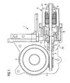
- eine Schnittzeichnung eines beispielhaften Stellantriebs mit einem Getriebegehäuse und mit einem Motor-gehäuse gemäß der Erfindung,
- FIG 2
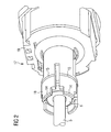
- eine perspektivische schematische Ansicht eines kombinierten Bürsten- und Lagergehäuses mit erfindungsgemäßen Erhebungen gemäß FIG 1,
- FIG 3
- eine perspektivische schematische Ansicht der FIG 2 in einer Aufrissdarstellung entlang der Antriebswelle des Stellantriebs,
- FIG 4
- eine vergrößerte Darstellung eines in eine Getriebegehäuseöffnung hineinragenden Lagergehäuses gemäß FIG 1,
- FIG 5
- eine Schnittzeichnung einer beispielhaft alternativen Lösung zum Aufbau einer Vorspannung mittels erfindungsgemäßer Stufen und vor Erreichen einer endgültigen Einschubposition des Lagergehäuses in der Getriebegehäuseöffnung und
- FIG 6
- eine Schnittzeichnung gemäß FIG 5 nach Erreichen der endgültigen Einschubposition des Lagergehäuses in der Getriebegehäuseöffnung.
- FIG. 1
- a sectional view of an exemplary actuator with a transmission housing and with a motor housing according to the invention,
- FIG. 2
- 1 is a perspective schematic view of a combined brush and bearing housing with elevations according to the invention according to FIG. 1,
- FIG. 3
- 2 shows a perspective schematic view of the FIG. 2 in an elevational view along the drive shaft of the actuator,
- FIG. 4
- an enlarged view of a projecting into a gear housing bearing housing according to FIG 1,
- FIG. 5
- a sectional view of an exemplary alternative solution for building a bias by means of steps according to the invention and before reaching a final insertion position of the bearing housing in the transmission housing opening and
- FIG. 6
- a sectional view of FIG 5 after reaching the final insertion position of the bearing housing in the transmission housing opening.
FIG 1 zeigt eine Schnittzeichnung eines beispielhaften Stellantriebs 1 mit einer Getriebeeinheit 2 und einer Motoreinheit 8. Die Getriebeeinheit 2 weist ein Getriebegehäuse 12 auf, in welchem ein Schneckenrad 4 sowie eine in das Schneckenrad 4 eingreifende Schneckenwelle 4 untergebracht sind. Die Motoreinheit 8 besteht aus einem Motorgehäuse 11, aus einem darin untergebrachten Läufer 9 mit einer Antriebswelle 5 sowie aus einem Lagergehäuse 18 auf der Antriebsseite der Motoreinheit 8. Die Schneckenwelle 3 sitzt auf dem freien Ende der Antriebswelle 5, wobei diese von der Motoreinheit 8 angetrieben wird und zum Teil im Motorgehäuse 11 untergebracht ist. Die Antriebswelle 5 ist motorseitig in einem der Getriebeeinheit 2 gegenüberliegenden Lager 6 sowie in einem Motorendlager 10 geführt. Im Beispiel der FIG 1 ist die Antriebswelle 5 einteilig ausgeführt. Eine zweiteilige Ausführung der Antriebswelle 5 in Motorwelle und Getriebewelle mit einem dazwischenliegenden Verbindungsglied ist ebenfalls denkbar.1 shows a sectional view of an exemplary actuator 1 with a
FIG 2 zeigt perspektivisch eine schematische Ansicht eines kombinierten Bürsten- und Lagergehäuses 17 entsprechend der FIG 1. Das Bürsten- und Lagergehäuse 17 setzt sich aus einem Bürstengehäuse 19 mit darin untergebrachten elektrischen Anschlüssen und Kohlebürsten für den Kommutator des Läufers 9 sowie aus einem Lagergehäuse 18 mit dem darin untergebrachten Lager 6 zusammen. Das Lagergehäuse 18 ist im Wesentlichen zylindrisch ausgeführt, so dass dieses leicht in eine korrespondierende Öffnung 7 des Getriebegehäuses 12 eingeführt werden kann.2 shows in perspective a schematic view of a combined brush and bearing
Gemäß der Erfindung sind Erhebungen 14, 15 als Klemmstellen auf der Außenseite bzw. am Außenumfang des Lagergehäuses 18 angebracht, welche gemäß einer Ausführungsform des Stellantriebs als umlaufende Wulste ausgebildet sind. Die Erhebungen 14, 15 bzw. die umlaufenden Wulste sind gemäß einer weiteren Ausführungsform so angeordnet, dass in axialer Richtung gesehen je eine Wulst 14, 15 im Endbereich des Lagers 6 angeordnet ist. Das Lager 6 ist im Beispiel der FIG 2 gemäß einer weiteren erfindungsgemäßen Ausführungsform eine Kalotte.According to the
FIG 3 zeigt eine perspektivische schematische Ansicht der FIG 2 in einer Aufrissdarstellung entlang der Antriebswelle 5 des Stellantriebs 1. In dieser Darstellung ist insbesondere die Einbettung der Kalotte 6 mit ihrer kugelförmigen Außenfläche in das Lagergehäuse 18 erkennbar.FIG. 3 shows a perspective schematic view of FIG. 2 in an elevational view along the
FIG 4 zeigt eine vergrößerte Darstellung eines in eine Getriebegehäuseöffnung 7 hineinragenden Lagergehäuses 18 gemäß FIG 1. Im rechten Teil der FIG 4 ist ein Teil des Bürstengehäuses 17 eines kombinierten Bürsten- und Lagergehäuses 11 dargestellt. Im linken Teil der Figur ist das entsprechende zylinderförmige Lagergehäuse 18 mit dem Lager 6 erkennbar. Im eingebauten Zustand des Stellantriebs 1 ist der eingezeichnete Außendurchmesser A des Lagergehäuses 18 geringfügig kleiner als der Innendurchmesser D der Getriebegehäuseöffnung 7. Dies wird durch die Beabstandung des Außenumfangs des Lagergehäuses 18 mittels der erfindungsgemäßen Erhebungen 14, 15 bzw. der ringförmigen Wulste bewirkt. Die sich zwischen den beiden Wulsten 14, 15 aufbauenden Vorspannkräfte F1, F2 wirken dabei zentrierend zur Mitte des Lagers 6 hin. Der sich zwischen den Wulsten ausbildende spannungsfreie Spalt 29 bildet vorteilhaft einen Bereich zum Aufbau einer Vorspannungsreserve. In diesen Bereich kann sich dann das Lagergehäuse 18 sozusagen "hineinwölben".4 shows an enlarged view of a projecting into a gear housing opening 7 bearing
Die FIG 4 zeigt bereits die Ausführung des Lagers 6 als Kalotte, in welcher die Antriebswelle 5 geführt ist. Mit R ist der maximale Radius der kugelförmigen Außenfläche bezeichnet. Mit dem Bezugszeichen 13 ist die Kontur der gegenüberliegenden Lagerschale gekennzeichnet. Die Kalotte 6 ist an ihrer Innenseite 19 angefast, so dass Ausgleichsverdrehungen durch die Kalotte 6 in gewissem Grad möglich sind. Die Getriebegehäuseöffnung 7 weist eine Verjüngung 16 in axialer Richtung zur Schneckenwelle 3 auf, die der Zentrierung der Schneckenwelle 3 beim Einführen der Antriebswelle 5 in die Getriebegehäuseöffnung 7 dient.FIG 4 already shows the execution of the
FIG 5 zeigt eine Schnittzeichnung einer beispielhaft alternativen Lösung zum Aufbau einer Vorspannung F1, F2 mittels Stufen 21-24 und vor Erreichen einer endgültigen Einschubposition des Lagergehäuses 28 in der Getriebegehäuseöffnung 27. Im Beispiel der FIG 5 sind sowohl die lagergehäuseseitigen Stufen 23, 24 als auch die dazu korrespondierenden getriebegehäuseseitigen Stufen 21, 22 bereits abgeschrägt. Der Winkel beträgt zwischen 30 und 60°, im Beispiel der FIG 5 in etwa 45°. Auf diese Weise wird ein Einschieben des Lagergehäuses 6 in die Öffnung 27 des Getriebegehäuses 12 erleichtert. Mit D1 ist der Abstand zu einer öffnungsseitigen weiteren Verjüngung und einem Ende des Lagergehäuses 28 eingezeichnet. Die vorliegende FIG 5 zeigt außerdem, dass das Lagergehäuse 6 in dieser Einschubposition noch relativ lose in der Getriebegehäuseöffnung 27 eingeschoben ist. Dies zeigt auch der zum Verständnis vergrößert dargestellte Spalt zwischen der Kalotte 6 und der diese umgebenden Lagerschale des Lagergehäuses 28.5 shows a sectional drawing of an exemplary alternative solution for building up a bias voltage F1, F2 by means of steps 21-24 and before reaching a final insertion position of the bearing
FIG 6 zeigt eine Schnittzeichnung gemäß FIG 5 nach Erreichen der endgültigen Einschubposition des Lagergehäuses 28 in der Getriebegehäuseöffnung 27. Im Beispiel der FIG 6 ist dies daran zu erkennen, dass sich der Abstand D2 zwischen der öffnungsseitigen weiteren Verjüngung und dem Ende des Lagergehäuses 28 geringfügig verringert hat, wie z.B. in einem Bereich von 0,5 mm bis 2 mm. Nach Erreichen der endgültigen Einschubposition sind nun die miteinander korrespondierenden Stufen 21, 23 sowie 22, 24 so verrastend verklemmt, dass in den Überschneidungsbereichen die erfindungsgemäße Vorspannung F1, F2 aufgebaut wird. Dies ist in FIG 6 auch daran ersichtlich, dass nun der noch in FIG vorhandene Spalt zwischen der Kalottenoberfläche und der dieser gegenüberliegenden Lagerschale verschwunden ist. Die Kalotte 6 ist nun in ihrer Position dauerhaft fixiert. Zugleich bilden sich Spalte 30, 31 als spannungsfreie Stellen aus, die als Bereiche zum Aufbau einer Vorspannungsreserve dienen.6 shows a sectional drawing according to FIG. 5 after reaching the final insertion position of the bearing
Claims (15)
dadurch gekennzeichnet,
dass die Außenseite des Lagergehäuses (18, 28) und die Innenseite der Getriebegehäuseöffnung (7, 27) geometrisch so aufeinander abgestimmt sind, dass sich nach Zusammenbau des Stellantriebs zwischen diesen Klemmstellen (14, 15, 21-24) und spannungsfreie Stellen (29-31) ausbilden.Actuator, comprising a gear unit (2) and a motor unit (8), wherein the gear unit (2) comprises a gear housing (12) and the motor unit (8) comprises a motor housing (11), an inner rotor (9) with a drive shaft (5) and a bearing housing (18, 28) on the drive side, wherein the bearing housing (18, 28) projects together with a bearing (6) and guided therein drive shaft (5) in an opening (7, 27) of the transmission housing (12) .
characterized,
that the outside of the bearing housing (18, 28) and the inside of the gearbox housing opening (7, 27) are geometrically matched to one another so that after assembly of the actuator between these clamping points (14, 15, 21-24) and stress-free locations (29- 31).
dadurch gekennzeichnet,
dass mittels der Klemmstellen (14, 15, 21-24) eine Vorspannkraft (F1, F2) aufbaubar ist, die über das Lagergehäuse (18, 28) auf das Lager (6) wirkt.Actuator according to claim 1,
characterized,
that by means of the clamping points (14, 15, 21-24) a biasing force (F1, F2) can be built, which acts on the bearing (6) via the bearing housing (18, 28).
dadurch gekennzeichnet,
dass mittels der Klemmstellen (14, 15, 21-24) zumindest eine umlaufende Vorspannkraft (F1, F2) im Bereich des Lagers (6) aufbaubar ist.Actuator according to claim 2,
characterized,
that by means of the clamping points (14, 15, 21-24) at least one circumferential biasing force (F1, F2) in the region of the bearing (6) can be built.
dadurch gekennzeichnet,
dass mittels der Klemmstellen (14, 15, 21-24) je eine umlaufende Vorspannkraft (F1, F2) in einem jeweiligen axialen Endbereich des Lagers (6) aufbaubar ist.Actuator according to claim 3,
characterized,
that by means of the clamping points (14, 15, 21-24) depending on a circumferential biasing force (F1, F2) in a respective axial end region of the bearing (6) is buildable.
dadurch gekennzeichnet,
characterized,
dadurch gekennzeichnet,
dass die Erhebungen (14, 15) zumindest eine Wulst ausbilden, welche am Außenumfang des Lagergehäuses (18) verläuft.Actuator according to claim 5,
characterized,
in that the elevations (14, 15) form at least one bead which extends on the outer circumference of the bearing housing (18).
dadurch gekennzeichnet,
dass die Erhebungen (14, 15) bzw. die zumindest eine Wulst in einem jeweiligen axialen Endbereich des Lagers (6) liegen.Actuator according to claim 5 or 6,
characterized,
that the elevations (14, 15) or the at least one bead in a respective axial end of the bearing (6) lie.
dadurch gekennzeichnet,
characterized,
dadurch gekennzeichnet,
characterized,
dadurch gekennzeichnet,
dass die korrespondierenden Stufen (21, 23; 22, 24) so abgeschrägt sind, dass sich diese in einer Verrastung verklemmen.Actuator according to claim 8 or 9,
characterized,
in that the corresponding steps (21, 23, 22, 24) are chamfered in such a way that they jam in one engagement.
dadurch gekennzeichnet,
dass das Lagergehäuse (18, 28) und die Getriebegehäuseöffnung (7, 27) zylinderförmig ausgebildet sind.Actuator according to one of the preceding claims,
characterized,
that the bearing housing (18, 28) and the gear housing opening (7, 27) are cylindrical in shape.
dadurch gekennzeichnet,
dass das Lager (6) eine Kalotte ist.Actuator according to one of the preceding claims,
characterized,
that the bearing (6) is a dome.
dadurch gekennzeichnet,
dass das Lagergehäuse (18, 28) ein Teil eines kombinierten Bürsten- und Lagergehäuses (17) ist.Actuator according to one of the preceding claims,
characterized,
in that the bearing housing (18, 28) is part of a combined brush and bearing housing (17).
dadurch gekennzeichnet,
dass das Lagergehäuse (18, 28) bzw. das kombinierte Bürsten-und Lagergehäuse (17) ein Kunststoff-Spritzgussteil ist.Actuator according to claim 13,
characterized,
that the bearing housing (18, 28) or the combined brush and bearing housing (17) is a plastic injection molded part.
Priority Applications (3)
| Application Number | Priority Date | Filing Date | Title |
|---|---|---|---|
| EP05015463A EP1744082B1 (en) | 2005-07-15 | 2005-07-15 | Actuator, especially for a motor vehicle |
| US11/457,306 US8646350B2 (en) | 2005-07-15 | 2006-07-13 | Actuator, in particular for a motor vehicle |
| CN200610105678.1A CN1897416B (en) | 2005-07-15 | 2006-07-17 | Actuator, in particular for a motor vehicle |
Applications Claiming Priority (1)
| Application Number | Priority Date | Filing Date | Title |
|---|---|---|---|
| EP05015463A EP1744082B1 (en) | 2005-07-15 | 2005-07-15 | Actuator, especially for a motor vehicle |
Publications (2)
| Publication Number | Publication Date |
|---|---|
| EP1744082A1 true EP1744082A1 (en) | 2007-01-17 |
| EP1744082B1 EP1744082B1 (en) | 2011-06-29 |
Family
ID=35124349
Family Applications (1)
| Application Number | Title | Priority Date | Filing Date |
|---|---|---|---|
| EP05015463A Ceased EP1744082B1 (en) | 2005-07-15 | 2005-07-15 | Actuator, especially for a motor vehicle |
Country Status (3)
| Country | Link |
|---|---|
| US (1) | US8646350B2 (en) |
| EP (1) | EP1744082B1 (en) |
| CN (1) | CN1897416B (en) |
Cited By (4)
| Publication number | Priority date | Publication date | Assignee | Title |
|---|---|---|---|---|
| DE102013200128A1 (en) * | 2013-01-08 | 2014-07-10 | Robert Bosch Gmbh | Bearing device for armature shaft of transmission-drive unit in motor vehicle, has body accommodated in retainer by connection, where connection is radially engaged into retainer and force-loaded axially in direction against contact surface |
| EP2700149B1 (en) * | 2011-04-18 | 2020-06-03 | Sew-Eurodrive GmbH & Co. KG | Drive |
| WO2022018005A1 (en) * | 2020-07-21 | 2022-01-27 | Brose Fahrzeugteile Se & Co. Kommanditgesellschaft, Bamberg | Brush system and method for coating a brush |
| US11781636B1 (en) * | 2022-06-07 | 2023-10-10 | Toyota Boshoku Kabushiki Kaisha | Gearbox for vehicle seat |
Families Citing this family (6)
| Publication number | Priority date | Publication date | Assignee | Title |
|---|---|---|---|---|
| DE102009028133A1 (en) * | 2009-07-30 | 2011-02-03 | Robert Bosch Gmbh | Storage facility |
| DE102009046105A1 (en) * | 2009-10-28 | 2011-05-05 | Robert Bosch Gmbh | Electric motor for a car actuator or wiper drive |
| CN103185130B (en) * | 2011-12-31 | 2017-10-24 | 德昌电机(深圳)有限公司 | Drive device and its gear |
| DE102013215808A1 (en) * | 2013-08-09 | 2015-02-12 | Brose Fahrzeugteile GmbH & Co. Kommanditgesellschaft, Würzburg | Rotor hub assembly, electric fan |
| JP6565239B2 (en) * | 2015-03-17 | 2019-08-28 | 株式会社デンソー | motor |
| DE102015213753B4 (en) * | 2015-07-21 | 2022-09-15 | Brose Fahrzeugteile Se & Co. Kommanditgesellschaft, Bamberg | Process for manufacturing a motor vehicle actuator |
Citations (7)
| Publication number | Priority date | Publication date | Assignee | Title |
|---|---|---|---|---|
| FR2375572A1 (en) * | 1976-12-23 | 1978-07-21 | Pflieger Roger | Positional adjustment for sighting gear - has worm gear disengaged to permit initial positioning and engaged for fine adjustments |
| US4987791A (en) * | 1988-03-04 | 1991-01-29 | Mabuchi Motor Company, Ltd. | Miniature motor with a worm reduction gear |
| DE19541118A1 (en) * | 1995-09-12 | 1997-03-13 | Brose Fahrzeugteile | Vehicle displacement drive gear e.g. for window mechanism or seat adjustment |
| EP0869295A2 (en) | 1997-04-02 | 1998-10-07 | Mabuchi Motor Kabushiki Kaisha | Motor assembly with reduction gear |
| US6014915A (en) * | 1998-06-11 | 2000-01-18 | Precision Products Systems, Llc | Gear housing |
| EP0998013A1 (en) * | 1998-05-14 | 2000-05-03 | Mabuchi Motor Co., Ltd | Small-sized motor with worm speed reducer and method of manufacturing the motor |
| DE10259957A1 (en) * | 2002-12-20 | 2004-07-15 | Robert Bosch Gmbh | Gear drive unit |
Family Cites Families (15)
| Publication number | Priority date | Publication date | Assignee | Title |
|---|---|---|---|---|
| US1680257A (en) * | 1925-05-09 | 1928-08-07 | Western States Machine Co | Gyratory centrifugal |
| US1693748A (en) * | 1927-01-24 | 1928-12-04 | Bohn Aluminium & Brass Corp | Method of making ball and socket joints |
| US2711352A (en) * | 1952-11-01 | 1955-06-21 | Hasko John | Spherical bearing |
| US2804679A (en) * | 1954-08-23 | 1957-09-03 | Southwest Products Co | Method of making bearings and rod end bearings |
| US2935885A (en) * | 1958-03-25 | 1960-05-10 | Illinois Tool Works | Multiple skew-axis gearing |
| US3303557A (en) * | 1961-03-03 | 1967-02-14 | Fafnir Bearing Co | Method of making antifriction bearings |
| US3256451A (en) * | 1963-02-15 | 1966-06-14 | Forgflo Corp | Hydrodynamic bearings in a motor |
| US4105261A (en) * | 1976-10-29 | 1978-08-08 | The United States Of America As Represented By The Administrator Of The National Aeronautics And Space Administration | Spherical bearing |
| US4399380A (en) * | 1980-08-29 | 1983-08-16 | Jidosha Denki Kogyo Kabushiki Kaisha | Air cooled wiper motor |
| DE3322863A1 (en) * | 1983-06-24 | 1985-01-10 | Brose Fahrzeugteile GmbH & Co KG, 8630 Coburg | ADJUSTING GEARBOXES IN A MOTOR VEHICLE |
| JP2521403Y2 (en) * | 1991-06-04 | 1996-12-25 | 株式会社ミツバ | Small motor with worm reducer |
| US5917258A (en) * | 1997-10-08 | 1999-06-29 | Siemens Canada Limited | Bearing assembly for an ultra quiet electric motor |
| DE19839640B4 (en) * | 1998-08-31 | 2004-12-23 | Siemens Ag | Motor with a spherical bearing that can be fixed in a bearing seat with axial play adjustment for a rotor shaft and method for axial play adjustment for a rotor shaft |
| US6252321B1 (en) * | 1999-06-23 | 2001-06-26 | General Electric Company | Endshield assembly with alignable bearing for an electric motor |
| CN2531176Y (en) * | 2002-02-09 | 2003-01-15 | 江从寿 | Friction driven buncher |
-
2005
- 2005-07-15 EP EP05015463A patent/EP1744082B1/en not_active Ceased
-
2006
- 2006-07-13 US US11/457,306 patent/US8646350B2/en not_active Expired - Fee Related
- 2006-07-17 CN CN200610105678.1A patent/CN1897416B/en not_active Expired - Fee Related
Patent Citations (7)
| Publication number | Priority date | Publication date | Assignee | Title |
|---|---|---|---|---|
| FR2375572A1 (en) * | 1976-12-23 | 1978-07-21 | Pflieger Roger | Positional adjustment for sighting gear - has worm gear disengaged to permit initial positioning and engaged for fine adjustments |
| US4987791A (en) * | 1988-03-04 | 1991-01-29 | Mabuchi Motor Company, Ltd. | Miniature motor with a worm reduction gear |
| DE19541118A1 (en) * | 1995-09-12 | 1997-03-13 | Brose Fahrzeugteile | Vehicle displacement drive gear e.g. for window mechanism or seat adjustment |
| EP0869295A2 (en) | 1997-04-02 | 1998-10-07 | Mabuchi Motor Kabushiki Kaisha | Motor assembly with reduction gear |
| EP0998013A1 (en) * | 1998-05-14 | 2000-05-03 | Mabuchi Motor Co., Ltd | Small-sized motor with worm speed reducer and method of manufacturing the motor |
| US6014915A (en) * | 1998-06-11 | 2000-01-18 | Precision Products Systems, Llc | Gear housing |
| DE10259957A1 (en) * | 2002-12-20 | 2004-07-15 | Robert Bosch Gmbh | Gear drive unit |
Cited By (4)
| Publication number | Priority date | Publication date | Assignee | Title |
|---|---|---|---|---|
| EP2700149B1 (en) * | 2011-04-18 | 2020-06-03 | Sew-Eurodrive GmbH & Co. KG | Drive |
| DE102013200128A1 (en) * | 2013-01-08 | 2014-07-10 | Robert Bosch Gmbh | Bearing device for armature shaft of transmission-drive unit in motor vehicle, has body accommodated in retainer by connection, where connection is radially engaged into retainer and force-loaded axially in direction against contact surface |
| WO2022018005A1 (en) * | 2020-07-21 | 2022-01-27 | Brose Fahrzeugteile Se & Co. Kommanditgesellschaft, Bamberg | Brush system and method for coating a brush |
| US11781636B1 (en) * | 2022-06-07 | 2023-10-10 | Toyota Boshoku Kabushiki Kaisha | Gearbox for vehicle seat |
Also Published As
| Publication number | Publication date |
|---|---|
| US8646350B2 (en) | 2014-02-11 |
| CN1897416B (en) | 2012-04-25 |
| US20070012125A1 (en) | 2007-01-18 |
| CN1897416A (en) | 2007-01-17 |
| EP1744082B1 (en) | 2011-06-29 |
Similar Documents
| Publication | Publication Date | Title |
|---|---|---|
| DE69728692T2 (en) | Geared motor, in particular for driving accessories in motor vehicles | |
| EP0918671B1 (en) | Electric drive unit | |
| US8646350B2 (en) | Actuator, in particular for a motor vehicle | |
| DE102006002395B4 (en) | Ball joint, and method for producing a joint housing | |
| EP0836018A1 (en) | Ball joint and method of mounting | |
| DE102008042281A1 (en) | Shaft bearing for use in worm gear of electric power steering system of motor vehicle, has holder connected with shaft, accommodating inner ring and comprising recesses enabling pivot movement towards section of holder | |
| EP2115859B1 (en) | Gearbox drive unit, and method for producing a gearbox drive unit | |
| EP1797353B1 (en) | Method for producing a gearbox, and corresponding gearbox | |
| DE102016214041B4 (en) | automotive actuator | |
| WO2010149526A2 (en) | Commutator bearing | |
| EP1579125B1 (en) | Gear transmission unit | |
| EP2659152B1 (en) | Drive unit with bearing device and adjustment drive | |
| EP2138731A1 (en) | Bearing bush and bearing | |
| WO2011091888A1 (en) | Bearing device for a drive unit and adjustment drive having a bearing device | |
| DE102011085489A1 (en) | Axial play compensating device for e.g. electromotive auxiliary drive for motor car, has bevel attached to device, and play compensating element designed such that element is slidably guided along bevel for compensating arising axial play | |
| DE102007057706A1 (en) | Electric drive motor, in particular for an aggragate in a motor vehicle | |
| DE102007023389A1 (en) | Shaft starting arrangement; Actuator and window regulator | |
| DE102020200223A1 (en) | Receiving element, method for producing a receiving element and electrical machine with a receiving element | |
| EP1935078B1 (en) | Drive unit with rotationally fixed bearing element | |
| EP2147496B1 (en) | Actuator and window lifting device | |
| EP1744436A1 (en) | Electric machine with means for compensating axial play, actuator comprising said electric machine and use of said electric machine in a motor vehicle | |
| DE102008040552A1 (en) | Spring device and device with a rotatably mounted relative to an axial axis shaft | |
| DE102020215344A1 (en) | Steering device with a worm gear | |
| EP1544488B1 (en) | Gear unit, especially window regulator, comprising an adapting element | |
| DE102008029463A1 (en) | Electromotive auxiliary drive e.g. windscreen wiper drive, for vehicle, has bearing comprising projection extending into annular groove that is provided at gear wheel and concentrically enclosing shaft axis |
Legal Events
| Date | Code | Title | Description |
|---|---|---|---|
| PUAI | Public reference made under article 153(3) epc to a published international application that has entered the european phase |
Free format text: ORIGINAL CODE: 0009012 |
|
| AK | Designated contracting states |
Kind code of ref document: A1 Designated state(s): AT BE BG CH CY CZ DE DK EE ES FI FR GB GR HU IE IS IT LI LT LU LV MC NL PL PT RO SE SI SK TR |
|
| AX | Request for extension of the european patent |
Extension state: AL BA HR MK YU |
|
| 17P | Request for examination filed |
Effective date: 20070205 |
|
| AKX | Designation fees paid |
Designated state(s): DE FR |
|
| RAP1 | Party data changed (applicant data changed or rights of an application transferred) |
Owner name: BROSE FAHRZEUGTEILE GMBH & CO. KG |
|
| RAP1 | Party data changed (applicant data changed or rights of an application transferred) |
Owner name: BROSE FAHRZEUGTEILE GMBH & CO. KG, WUERZBURG |
|
| 17Q | First examination report despatched |
Effective date: 20100319 |
|
| GRAP | Despatch of communication of intention to grant a patent |
Free format text: ORIGINAL CODE: EPIDOSNIGR1 |
|
| RIC1 | Information provided on ipc code assigned before grant |
Ipc: F16C 23/04 20060101ALN20110201BHEP Ipc: F16H 1/16 20060101ALI20110201BHEP Ipc: F16C 33/08 20060101ALN20110201BHEP Ipc: F16H 57/02 20060101AFI20110201BHEP |
|
| GRAS | Grant fee paid |
Free format text: ORIGINAL CODE: EPIDOSNIGR3 |
|
| GRAA | (expected) grant |
Free format text: ORIGINAL CODE: 0009210 |
|
| REG | Reference to a national code |
Ref country code: DE Ref legal event code: R082 Ref document number: 502005011547 Country of ref document: DE Representative=s name: PAE REINHARD, SKUHRA, WEISE & PARTNER GBR, DE Ref country code: DE Ref legal event code: R082 Ref document number: 502005011547 Country of ref document: DE Representative=s name: ISARPATENT GBR PATENT- UND RECHTSANWAELTE, DE Ref country code: DE Ref legal event code: R082 Ref document number: 502005011547 Country of ref document: DE Representative=s name: ISARPATENT PATENTANWAELTE BEHNISCH, BARTH, CHA, DE Ref country code: DE Ref legal event code: R082 Ref document number: 502005011547 Country of ref document: DE Representative=s name: ISARPATENT - PATENTANWAELTE- UND RECHTSANWAELT, DE |
|
| AK | Designated contracting states |
Kind code of ref document: B1 Designated state(s): DE FR |
|
| REG | Reference to a national code |
Ref country code: DE Ref legal event code: R096 Ref document number: 502005011547 Country of ref document: DE Effective date: 20110818 |
|
| PLBE | No opposition filed within time limit |
Free format text: ORIGINAL CODE: 0009261 |
|
| STAA | Information on the status of an ep patent application or granted ep patent |
Free format text: STATUS: NO OPPOSITION FILED WITHIN TIME LIMIT |
|
| 26N | No opposition filed |
Effective date: 20120330 |
|
| REG | Reference to a national code |
Ref country code: DE Ref legal event code: R097 Ref document number: 502005011547 Country of ref document: DE Effective date: 20120330 |
|
| REG | Reference to a national code |
Ref country code: FR Ref legal event code: PLFP Year of fee payment: 12 |
|
| REG | Reference to a national code |
Ref country code: FR Ref legal event code: PLFP Year of fee payment: 13 |
|
| REG | Reference to a national code |
Ref country code: FR Ref legal event code: PLFP Year of fee payment: 14 |
|
| PGFP | Annual fee paid to national office [announced via postgrant information from national office to epo] |
Ref country code: DE Payment date: 20180731 Year of fee payment: 14 |
|
| PGFP | Annual fee paid to national office [announced via postgrant information from national office to epo] |
Ref country code: FR Payment date: 20190619 Year of fee payment: 15 |
|
| REG | Reference to a national code |
Ref country code: DE Ref legal event code: R119 Ref document number: 502005011547 Country of ref document: DE |
|
| PG25 | Lapsed in a contracting state [announced via postgrant information from national office to epo] |
Ref country code: DE Free format text: LAPSE BECAUSE OF NON-PAYMENT OF DUE FEES Effective date: 20200201 |
|
| PG25 | Lapsed in a contracting state [announced via postgrant information from national office to epo] |
Ref country code: FR Free format text: LAPSE BECAUSE OF NON-PAYMENT OF DUE FEES Effective date: 20200731 |