EP1744082A1 - Actionneur, notamment pour un véhicule automobile - Google Patents
Actionneur, notamment pour un véhicule automobile Download PDFInfo
- Publication number
- EP1744082A1 EP1744082A1 EP05015463A EP05015463A EP1744082A1 EP 1744082 A1 EP1744082 A1 EP 1744082A1 EP 05015463 A EP05015463 A EP 05015463A EP 05015463 A EP05015463 A EP 05015463A EP 1744082 A1 EP1744082 A1 EP 1744082A1
- Authority
- EP
- European Patent Office
- Prior art keywords
- bearing
- housing
- bearing housing
- actuator according
- actuator
- Prior art date
- Legal status (The legal status is an assumption and is not a legal conclusion. Google has not performed a legal analysis and makes no representation as to the accuracy of the status listed.)
- Granted
Links
Images


Classifications
-
- F—MECHANICAL ENGINEERING; LIGHTING; HEATING; WEAPONS; BLASTING
- F16—ENGINEERING ELEMENTS AND UNITS; GENERAL MEASURES FOR PRODUCING AND MAINTAINING EFFECTIVE FUNCTIONING OF MACHINES OR INSTALLATIONS; THERMAL INSULATION IN GENERAL
- F16H—GEARING
- F16H57/00—General details of gearing
- F16H57/02—Gearboxes; Mounting gearing therein
- F16H57/021—Shaft support structures, e.g. partition walls, bearing eyes, casing walls or covers with bearings
-
- F—MECHANICAL ENGINEERING; LIGHTING; HEATING; WEAPONS; BLASTING
- F16—ENGINEERING ELEMENTS AND UNITS; GENERAL MEASURES FOR PRODUCING AND MAINTAINING EFFECTIVE FUNCTIONING OF MACHINES OR INSTALLATIONS; THERMAL INSULATION IN GENERAL
- F16C—SHAFTS; FLEXIBLE SHAFTS; ELEMENTS OR CRANKSHAFT MECHANISMS; ROTARY BODIES OTHER THAN GEARING ELEMENTS; BEARINGS
- F16C23/00—Bearings for exclusively rotary movement adjustable for aligning or positioning
- F16C23/02—Sliding-contact bearings
- F16C23/04—Sliding-contact bearings self-adjusting
-
- F—MECHANICAL ENGINEERING; LIGHTING; HEATING; WEAPONS; BLASTING
- F16—ENGINEERING ELEMENTS AND UNITS; GENERAL MEASURES FOR PRODUCING AND MAINTAINING EFFECTIVE FUNCTIONING OF MACHINES OR INSTALLATIONS; THERMAL INSULATION IN GENERAL
- F16H—GEARING
- F16H57/00—General details of gearing
- F16H57/02—Gearboxes; Mounting gearing therein
- F16H57/039—Gearboxes for accommodating worm gears
-
- F—MECHANICAL ENGINEERING; LIGHTING; HEATING; WEAPONS; BLASTING
- F16—ENGINEERING ELEMENTS AND UNITS; GENERAL MEASURES FOR PRODUCING AND MAINTAINING EFFECTIVE FUNCTIONING OF MACHINES OR INSTALLATIONS; THERMAL INSULATION IN GENERAL
- F16H—GEARING
- F16H1/00—Toothed gearings for conveying rotary motion
- F16H1/02—Toothed gearings for conveying rotary motion without gears having orbital motion
- F16H1/04—Toothed gearings for conveying rotary motion without gears having orbital motion involving only two intermeshing members
- F16H1/12—Toothed gearings for conveying rotary motion without gears having orbital motion involving only two intermeshing members with non-parallel axes
- F16H1/16—Toothed gearings for conveying rotary motion without gears having orbital motion involving only two intermeshing members with non-parallel axes comprising worm and worm-wheel
-
- F—MECHANICAL ENGINEERING; LIGHTING; HEATING; WEAPONS; BLASTING
- F16—ENGINEERING ELEMENTS AND UNITS; GENERAL MEASURES FOR PRODUCING AND MAINTAINING EFFECTIVE FUNCTIONING OF MACHINES OR INSTALLATIONS; THERMAL INSULATION IN GENERAL
- F16H—GEARING
- F16H57/00—General details of gearing
- F16H57/02—Gearboxes; Mounting gearing therein
- F16H57/021—Shaft support structures, e.g. partition walls, bearing eyes, casing walls or covers with bearings
- F16H2057/0213—Support of worm gear shafts
-
- Y—GENERAL TAGGING OF NEW TECHNOLOGICAL DEVELOPMENTS; GENERAL TAGGING OF CROSS-SECTIONAL TECHNOLOGIES SPANNING OVER SEVERAL SECTIONS OF THE IPC; TECHNICAL SUBJECTS COVERED BY FORMER USPC CROSS-REFERENCE ART COLLECTIONS [XRACs] AND DIGESTS
- Y10—TECHNICAL SUBJECTS COVERED BY FORMER USPC
- Y10T—TECHNICAL SUBJECTS COVERED BY FORMER US CLASSIFICATION
- Y10T74/00—Machine element or mechanism
- Y10T74/18—Mechanical movements
- Y10T74/18568—Reciprocating or oscillating to or from alternating rotary
- Y10T74/18792—Reciprocating or oscillating to or from alternating rotary including worm
-
- Y—GENERAL TAGGING OF NEW TECHNOLOGICAL DEVELOPMENTS; GENERAL TAGGING OF CROSS-SECTIONAL TECHNOLOGIES SPANNING OVER SEVERAL SECTIONS OF THE IPC; TECHNICAL SUBJECTS COVERED BY FORMER USPC CROSS-REFERENCE ART COLLECTIONS [XRACs] AND DIGESTS
- Y10—TECHNICAL SUBJECTS COVERED BY FORMER USPC
- Y10T—TECHNICAL SUBJECTS COVERED BY FORMER US CLASSIFICATION
- Y10T74/00—Machine element or mechanism
- Y10T74/19—Gearing
- Y10T74/19642—Directly cooperating gears
- Y10T74/19698—Spiral
- Y10T74/19828—Worm
-
- Y—GENERAL TAGGING OF NEW TECHNOLOGICAL DEVELOPMENTS; GENERAL TAGGING OF CROSS-SECTIONAL TECHNOLOGIES SPANNING OVER SEVERAL SECTIONS OF THE IPC; TECHNICAL SUBJECTS COVERED BY FORMER USPC CROSS-REFERENCE ART COLLECTIONS [XRACs] AND DIGESTS
- Y10—TECHNICAL SUBJECTS COVERED BY FORMER USPC
- Y10T—TECHNICAL SUBJECTS COVERED BY FORMER US CLASSIFICATION
- Y10T74/00—Machine element or mechanism
- Y10T74/21—Elements
- Y10T74/2186—Gear casings
Definitions
- the invention relates to an actuator with a gear unit and a motor unit.
- the gear unit has a gear housing and the motor unit a motor housing, an inner rotor with a drive shaft and in particular a cylindrical bearing housing on the drive side.
- the bearing housing protrudes into an opening of the transmission housing together with a bearing and the drive shaft guided therein.
- the invention also relates to a use of the actuator in a motor vehicle.
- Actuators such as power window drives or actuators to operate the sunroof, are already known. They have a gear unit and a motor unit.
- the gear unit has a worm wheel and a gear shaft realized as a worm shaft.
- the motor unit consists of a motor housing, a brush housing and an internal rotor.
- the rotor is designed as a so-called rotor package with a variety of attached to the motor shaft slats.
- the gear shaft and the motor shaft can also be made in one piece as a common drive shaft.
- the motor housing is flanged to the gear housing.
- a mostly cylindrical extension of the brush housing projects with the drive shaft and the worm shaft located at the free end of the drive shaft into a corresponding opening of the gear housing.
- the extension of the brush housing serves as a holder for a bearing in which the drive shaft is guided.
- the cylindrical extension can also be formed as a separate bearing housing or alternatively form a common brush and bearing housing with the brush housing.
- An actuator in which a motor housing is flanged to a transmission housing.
- the motor housing protrudes partly into a gear housing opening, wherein the protruding part encloses a spherical bearing, in which a motor shaft is guided.
- the opposite to the transmission and accommodated in the cylindrical bearing housing bearing serves as a compensation element to compensate for manufacturing tolerances in the assembly of the actuator.
- the bearing is displaced axially to some extent in its holder. If the bearing is a spherical outside surface which, within certain limits, can move in a corresponding spherical shell of the bearing support, it is also possible to compensate for deflections and radial offsets of the drive shaft. So that the bearing remains fixed after assembly in its position, a bias is applied to this.
- a common problem is that the bearing introduced into the gearbox housing opening with the cylindrical bearing housing becomes loose after a certain period of operation and, in the case of a dome, can rotate in its bearing shell.
- the reason for this are settlement processes, which are subject to plastics during a permanent load. This reduces a still existing in the new state preload in such a way that over time, the bearing or the cap begins to dissolve in the bearing bracket. This leads to wear of the bearing or the dome and thus premature failure of the actuator.
- the noise increases during actuation of the actuator.
- the object of the invention is to provide a simplified actuator, which allows a permanent fixation of a bearing.
- a biasing force is advantageously effected, which permanently fixes the bearing over the intended operating time of the actuator.
- the biasing force in turn causes an advantageously permanent frictional engagement between the outer periphery of the bearing and the bearing shell opposite this.
- gaps as stress-free areas form areas into which a bias reserve can build up, which permanently acts on the bearing.
- Another advantage is that the life of such an actuator is increased.
- a biasing force can be built up by means of the clamping points, which acts on the bearing via the bearing housing.
- the biasing force acts preferably at least circumferentially in the region of the bearing. This has the advantage that a uniform biasing force acts on the bearing from all sides.
- each a circumferential biasing force in a respective axial end region of the bearing can be built up.
- a centering force is exerted on the bearing in an advantageous manner. Any laterally acting on the bearing biasing forces, which could possibly lead to tilting of the bearing are avoided in this way.
- the bearing is particularly well axially fixed by the centering force and in the case of a dome as a bearing against rotation. The bearing remains clamped, so to speak, between the two peripherally applied preload forces.
- the inner cross section of the gearbox housing opening in the region of the bearing remains substantially the same.
- the inner cross section is circular.
- surveys are provided as terminal points.
- the biasing force is generated according to the invention.
- the elevations may be located selectively or linearly on the outer circumference of the bearing housing.
- the surveys may e.g. also have the form of lenses or bars with a maximum height of 1 mm.
- the elevations preferably form at least one bead, which runs on the outer circumference of the bearing housing, so that the biasing force advantageously acts uniformly on the outer circumference of the bearing.
- the elevations or the at least one bead lie in a respective axial end region of the bearing, so that the respective circumferential preload force can advantageously act centering on the bearing.
- the cross section of the bearing housing is reduced axially in at least one stage in the region of the bearing.
- the inner cross section of the transmission housing opening decreases in a corresponding manner axially in at least one stage.
- the gear housing opening tapers axially in the direction of the worm shaft.
- the insertion of the bearing housing into the gear housing opening is also facilitated during assembly of the actuator. After inserting the bearing housing, in particular shortly before reaching the final insertion position, the corresponding stages jam against each other to terminal points according to the invention.
- the step height is less than 1 mm, in particular, this is in a range of 0.1 to 0.5 mm.
- the cross section of the bearing housing decreases in the axial end region of the bearing in each case a step.
- the inner cross section of the transmission housing opening is reduced axially in two stages.
- corresponding steps in the inner cross-section of the gear housing opening and on the outer circumference of the bearing housing jam together to form the clamping points according to the invention.
- the resulting circumferential preload forces have an advantageous effect centering on the bearing.
- the steps can be chamfered so that they jam in a catch.
- the steps are chamfered in a range of 30 ° to 60 °.
- the bearing is a dome with a spherical outer surface for both embodiments.
- This outer surface can move within certain limits in a corresponding spherical shell of the bearing housing. A caused by manufacturing and / or assembly tolerances bending and a radial offset of the drive shaft to a small extent are compensated advantageous by the possible compensation rotation of the calotte.
- the dome is preferably made of a sintered material.
- the porous structure of the sintered material can absorb a lubricant, in particular a lubricating oil, for lubricating the drive shaft guided inside the dome.
- the bearing housing is part of a combined brush and bearing housing.
- plug contacts are provided which are guided electrically in the interior of the brush housing to the brush in the commutator of the rotor.
- the bearing housing or the combined brush and bearing housing with the elevations, beads or steps is a plastic injection molded part.
- Possible plastics are e.g. Polypropylene or polyamide.
- a particularly suitable type of plastic is PA 6.6.
- the plastic has a certain elasticity, which is particularly suitable for building up a biasing force in response to a mechanical deformation.
- the elastic mechanical deformation is caused by resulting bending moments during insertion into the opening of the transmission housing.
- a complex component such as e.g. manufacture the combined brush and bearing housing with the integrated engine mount, in one production step.
- An actuator according to the invention can be advantageously used in a motor vehicle, since in particular there a high number of compact actuators, such as. to lift the window or to open and close a sliding roof, is needed.
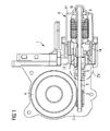
- the gear unit 2 has a gear housing 12 in which a worm wheel 4 and a worm shaft 4 engaging in the worm 4 are housed.
- the motor unit 8 consists of a motor housing 11, a rotor 9 accommodated therein with a drive shaft 5 and a bearing housing 18 on the drive side of the motor unit 8.
- the worm shaft 3 sits on the free end of the drive shaft 5 and is driven by the motor unit 8 is and is housed in part in the motor housing 11.
- the drive shaft 5 is guided on the motor side in a bearing 2 opposite the gear unit 2 and in a motor end bearing 10.
- the drive shaft 5 is made in one piece.
- a two-piece version of the drive shaft 5 in the motor shaft and gear shaft with an intermediate link is also conceivable.
- the brush and bearing housing 17 is composed of a brush housing 19 with electrical terminals and carbon brushes housed therein for the commutator of the rotor 9 and a bearing housing 18 the camp 6 housed therein together.
- the bearing housing 18 is designed substantially cylindrical, so that it can be easily inserted into a corresponding opening 7 of the gear housing 12.
- elevations 14, 15 are mounted as clamping points on the outer side or on the outer circumference of the bearing housing 18, which are formed according to an embodiment of the actuator as circumferential beads.
- the elevations 14, 15 or the circumferential beads are arranged according to a further embodiment, that viewed in the axial direction depending a bead 14, 15 is arranged in the end region of the bearing 6.
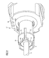
- the bearing 6 is a dome in the example of FIG 2 according to another embodiment of the invention.
- FIG. 3 shows a perspective schematic view of FIG. 2 in an elevational view along the drive shaft 5 of the actuator 1.
- the cap 6 with its spherical outer surface into the bearing housing 18 can be seen.
- FIG 4 shows an enlarged view of a projecting into a gear housing opening 7 bearing housing 18 according to FIG 1.
- a part of the brush housing 17 of a combined brush and bearing housing 11 is shown.
- the corresponding cylindrical bearing housing 18 with the bearing 6 can be seen.
- the drawn Outer diameter A of the bearing housing 18 is slightly smaller than the inner diameter D of the transmission housing opening 7. This is effected by the spacing of the outer periphery of the bearing housing 18 by means of the elevations 14, 15 or the annular beads according to the invention.
- the prestressing forces F1, F2 which build up between the two beads 14, 15 act centered towards the center of the bearing 6.
- the stress-free gap 29 forming between the beads advantageously forms an area for establishing a bias reserve. In this area, then, the bearing housing 18, so to speak, "bulge in”.
- FIG 4 already shows the execution of the bearing 6 as a calotte, in which the drive shaft 5 is guided.
- R denotes the maximum radius of the spherical outer surface.
- the reference numeral 13 the contour of the opposite bearing shell is marked.
- the dome 6 is chamfered on its inner side 19, so that compensating twists through the dome 6 are possible to some extent.
- the gear housing opening 7 has a taper 16 in the axial direction to the worm shaft 3, which serves to center the worm shaft 3 during insertion of the drive shaft 5 in the gear housing opening 7.
- FIG 5 shows a sectional drawing of an exemplary alternative solution for building up a bias voltage F1, F2 by means of steps 21-24 and before reaching a final insertion position of the bearing housing 28 in the gear housing opening 27.
- both the bearing housing side stages 23, 24 and the corresponding gear housing-side steps 21, 22 already bevelled.
- the angle is between 30 and 60 °, in the example of FIG 5 in about 45 °.
- D1 the distance to an opening-side further taper and one end of the bearing housing 28 is located.
- the present FIG 5 also shows that the bearing housing 6 in this insertion position is still relatively loosely inserted in the gear housing opening 27. This is also shown by the enlarged gap for understanding between the cap 6 and the surrounding bearing shell of the bearing housing 28th
- FIG. 6 shows a sectional drawing according to FIG. 5 after reaching the final insertion position of the bearing housing 28 in the gearbox housing opening 27.
- this can be seen from the fact that the distance D2 between the opening-side further taper and the end of the bearing housing 28 is slightly reduced has, such as in a range of 0.5 mm to 2 mm.
- the mutually corresponding steps 21, 23 and 22, 24 are clamped so latching that in the overlapping areas, the bias of the invention F1, F2 is constructed.
- FIG. 6 shows that the gap between the dome surface and the opposite bearing shell still present in FIG has now disappeared.
- the calotte 6 is now permanently fixed in position.
- gaps 30, 31 form as stress-free areas, which serve as areas for building up a bias reserve.
Landscapes
- Engineering & Computer Science (AREA)
- General Engineering & Computer Science (AREA)
- Mechanical Engineering (AREA)
- Mounting Of Bearings Or Others (AREA)
- Connection Of Motors, Electrical Generators, Mechanical Devices, And The Like (AREA)
- General Details Of Gearings (AREA)
Priority Applications (3)
| Application Number | Priority Date | Filing Date | Title |
|---|---|---|---|
| EP05015463A EP1744082B1 (fr) | 2005-07-15 | 2005-07-15 | Actionneur, notamment pour un véhicule automobile |
| US11/457,306 US8646350B2 (en) | 2005-07-15 | 2006-07-13 | Actuator, in particular for a motor vehicle |
| CN200610105678.1A CN1897416B (zh) | 2005-07-15 | 2006-07-17 | 尤其用于汽车的伺服驱动装置 |
Applications Claiming Priority (1)
| Application Number | Priority Date | Filing Date | Title |
|---|---|---|---|
| EP05015463A EP1744082B1 (fr) | 2005-07-15 | 2005-07-15 | Actionneur, notamment pour un véhicule automobile |
Publications (2)
| Publication Number | Publication Date |
|---|---|
| EP1744082A1 true EP1744082A1 (fr) | 2007-01-17 |
| EP1744082B1 EP1744082B1 (fr) | 2011-06-29 |
Family
ID=35124349
Family Applications (1)
| Application Number | Title | Priority Date | Filing Date |
|---|---|---|---|
| EP05015463A Expired - Fee Related EP1744082B1 (fr) | 2005-07-15 | 2005-07-15 | Actionneur, notamment pour un véhicule automobile |
Country Status (3)
| Country | Link |
|---|---|
| US (1) | US8646350B2 (fr) |
| EP (1) | EP1744082B1 (fr) |
| CN (1) | CN1897416B (fr) |
Cited By (4)
| Publication number | Priority date | Publication date | Assignee | Title |
|---|---|---|---|---|
| DE102013200128A1 (de) * | 2013-01-08 | 2014-07-10 | Robert Bosch Gmbh | Lagereinrichtung für eine Ankerwelle einer Getriebe-Antriebseinheit und Getriebe-Antriebseinheit |
| EP2700149B1 (fr) * | 2011-04-18 | 2020-06-03 | Sew-Eurodrive GmbH & Co. KG | Dispositif d'entraînement |
| WO2022018005A1 (fr) * | 2020-07-21 | 2022-01-27 | Brose Fahrzeugteile Se & Co. Kommanditgesellschaft, Bamberg | Système et procédé à balais permettant le revêtement d'un balai |
| US11781636B1 (en) * | 2022-06-07 | 2023-10-10 | Toyota Boshoku Kabushiki Kaisha | Gearbox for vehicle seat |
Families Citing this family (6)
| Publication number | Priority date | Publication date | Assignee | Title |
|---|---|---|---|---|
| DE102009028133A1 (de) * | 2009-07-30 | 2011-02-03 | Robert Bosch Gmbh | Lagereinrichtung |
| DE102009046105A1 (de) * | 2009-10-28 | 2011-05-05 | Robert Bosch Gmbh | Elektromotor für einen Kfz-Stell- oder Wischerantrieb |
| CN103185130B (zh) * | 2011-12-31 | 2017-10-24 | 德昌电机(深圳)有限公司 | 驱动装置及其齿轮 |
| DE102013215808A1 (de) * | 2013-08-09 | 2015-02-12 | Brose Fahrzeugteile GmbH & Co. Kommanditgesellschaft, Würzburg | Rotornabenanordnung, elektrischer Lüfter |
| JP6565239B2 (ja) * | 2015-03-17 | 2019-08-28 | 株式会社デンソー | モータ |
| DE102015213753B4 (de) * | 2015-07-21 | 2022-09-15 | Brose Fahrzeugteile Se & Co. Kommanditgesellschaft, Bamberg | Verfahren zur Herstellung eines Kraftfahrzeug-Stellantriebs |
Citations (7)
| Publication number | Priority date | Publication date | Assignee | Title |
|---|---|---|---|---|
| FR2375572A1 (fr) * | 1976-12-23 | 1978-07-21 | Pflieger Roger | Dispositif pour le reglage du positionnement d'un appareil orientable |
| US4987791A (en) * | 1988-03-04 | 1991-01-29 | Mabuchi Motor Company, Ltd. | Miniature motor with a worm reduction gear |
| DE19541118A1 (de) * | 1995-09-12 | 1997-03-13 | Brose Fahrzeugteile | Getriebe für Verstellantriebe in Kraftfahrzeugen |
| EP0869295A2 (fr) | 1997-04-02 | 1998-10-07 | Mabuchi Motor Kabushiki Kaisha | Ensemble moteur avec réducteur de vitesse |
| US6014915A (en) * | 1998-06-11 | 2000-01-18 | Precision Products Systems, Llc | Gear housing |
| EP0998013A1 (fr) * | 1998-05-14 | 2000-05-03 | Mabuchi Motor Co., Ltd | Moteur de taille reduite avec reducteur de la vitesse de la vis et procede de fabrication de ce moteur |
| DE10259957A1 (de) * | 2002-12-20 | 2004-07-15 | Robert Bosch Gmbh | Getriebe-Antriebseinheit |
Family Cites Families (15)
| Publication number | Priority date | Publication date | Assignee | Title |
|---|---|---|---|---|
| US1680257A (en) * | 1925-05-09 | 1928-08-07 | Western States Machine Co | Gyratory centrifugal |
| US1693748A (en) * | 1927-01-24 | 1928-12-04 | Bohn Aluminium & Brass Corp | Method of making ball and socket joints |
| US2711352A (en) * | 1952-11-01 | 1955-06-21 | Hasko John | Spherical bearing |
| US2804679A (en) * | 1954-08-23 | 1957-09-03 | Southwest Products Co | Method of making bearings and rod end bearings |
| US2935885A (en) * | 1958-03-25 | 1960-05-10 | Illinois Tool Works | Multiple skew-axis gearing |
| US3303557A (en) * | 1961-03-03 | 1967-02-14 | Fafnir Bearing Co | Method of making antifriction bearings |
| US3256451A (en) * | 1963-02-15 | 1966-06-14 | Forgflo Corp | Hydrodynamic bearings in a motor |
| US4105261A (en) * | 1976-10-29 | 1978-08-08 | The United States Of America As Represented By The Administrator Of The National Aeronautics And Space Administration | Spherical bearing |
| US4399380A (en) * | 1980-08-29 | 1983-08-16 | Jidosha Denki Kogyo Kabushiki Kaisha | Air cooled wiper motor |
| DE3322863A1 (de) * | 1983-06-24 | 1985-01-10 | Brose Fahrzeugteile GmbH & Co KG, 8630 Coburg | Verstell-getriebe in einem kraftfahrzeug |
| JP2521403Y2 (ja) * | 1991-06-04 | 1996-12-25 | 株式会社ミツバ | ウオーム減速機付小型モータ |
| US5917258A (en) * | 1997-10-08 | 1999-06-29 | Siemens Canada Limited | Bearing assembly for an ultra quiet electric motor |
| DE19839640B4 (de) * | 1998-08-31 | 2004-12-23 | Siemens Ag | Motor mit in einer Lageraufnahme mit Axialspieleinstellung für eine Rotorwelle fixierbarem Kalottenlager und Verfahren zur Axialspieleinstellung für eine Rotorwelle |
| US6252321B1 (en) * | 1999-06-23 | 2001-06-26 | General Electric Company | Endshield assembly with alignable bearing for an electric motor |
| CN2531176Y (zh) * | 2002-02-09 | 2003-01-15 | 江从寿 | 摩擦传动的无级变速器 |
-
2005
- 2005-07-15 EP EP05015463A patent/EP1744082B1/fr not_active Expired - Fee Related
-
2006
- 2006-07-13 US US11/457,306 patent/US8646350B2/en not_active Expired - Fee Related
- 2006-07-17 CN CN200610105678.1A patent/CN1897416B/zh not_active Expired - Fee Related
Patent Citations (7)
| Publication number | Priority date | Publication date | Assignee | Title |
|---|---|---|---|---|
| FR2375572A1 (fr) * | 1976-12-23 | 1978-07-21 | Pflieger Roger | Dispositif pour le reglage du positionnement d'un appareil orientable |
| US4987791A (en) * | 1988-03-04 | 1991-01-29 | Mabuchi Motor Company, Ltd. | Miniature motor with a worm reduction gear |
| DE19541118A1 (de) * | 1995-09-12 | 1997-03-13 | Brose Fahrzeugteile | Getriebe für Verstellantriebe in Kraftfahrzeugen |
| EP0869295A2 (fr) | 1997-04-02 | 1998-10-07 | Mabuchi Motor Kabushiki Kaisha | Ensemble moteur avec réducteur de vitesse |
| EP0998013A1 (fr) * | 1998-05-14 | 2000-05-03 | Mabuchi Motor Co., Ltd | Moteur de taille reduite avec reducteur de la vitesse de la vis et procede de fabrication de ce moteur |
| US6014915A (en) * | 1998-06-11 | 2000-01-18 | Precision Products Systems, Llc | Gear housing |
| DE10259957A1 (de) * | 2002-12-20 | 2004-07-15 | Robert Bosch Gmbh | Getriebe-Antriebseinheit |
Cited By (4)
| Publication number | Priority date | Publication date | Assignee | Title |
|---|---|---|---|---|
| EP2700149B1 (fr) * | 2011-04-18 | 2020-06-03 | Sew-Eurodrive GmbH & Co. KG | Dispositif d'entraînement |
| DE102013200128A1 (de) * | 2013-01-08 | 2014-07-10 | Robert Bosch Gmbh | Lagereinrichtung für eine Ankerwelle einer Getriebe-Antriebseinheit und Getriebe-Antriebseinheit |
| WO2022018005A1 (fr) * | 2020-07-21 | 2022-01-27 | Brose Fahrzeugteile Se & Co. Kommanditgesellschaft, Bamberg | Système et procédé à balais permettant le revêtement d'un balai |
| US11781636B1 (en) * | 2022-06-07 | 2023-10-10 | Toyota Boshoku Kabushiki Kaisha | Gearbox for vehicle seat |
Also Published As
| Publication number | Publication date |
|---|---|
| CN1897416B (zh) | 2012-04-25 |
| CN1897416A (zh) | 2007-01-17 |
| US20070012125A1 (en) | 2007-01-18 |
| US8646350B2 (en) | 2014-02-11 |
| EP1744082B1 (fr) | 2011-06-29 |
Similar Documents
| Publication | Publication Date | Title |
|---|---|---|
| EP1744082B1 (fr) | Actionneur, notamment pour un véhicule automobile | |
| DE69728692T2 (de) | Getriebemotor, insbesondere zum Antrieb von Zubehörteilen in Kraftfahrzeugen | |
| EP1797353B1 (fr) | Procede de fabrication d'une transmission et transmission ainsi fabriquee | |
| DE102006002395B4 (de) | Kugelgelenk, sowie Verfahren zur Herstellung eines Gelenkgehäuses | |
| EP0918671B1 (fr) | Unite d'entrainement electrique | |
| EP0836018A1 (fr) | Joint à rotule et procédé de montage | |
| DE102008042281A1 (de) | Wellenlagerung in einem Lenksystem und damit ausgestattetes Lenkgetriebe sowie Verfahren zur Herstellung einer Halterung dafür | |
| EP2115859B1 (fr) | Unité d'entraînement à engrenage et procédé de fabrication de celle-ci | |
| DE102016214041B4 (de) | Kraftfahrzeug-Stellantrieb | |
| WO2010149526A2 (fr) | Palier de collecteur | |
| EP2659152B1 (fr) | Unité d'entraînement avec dispositif de palier et entraînement de réglage | |
| EP1579125B1 (fr) | Unite d'entrainement de transmission | |
| DE102011085489A1 (de) | Spielkompensationseinrichtung sowie spielkompensierendes Axiallager, Motor und elektromotorischer Hilfsantrieb | |
| DE102007057706A1 (de) | Elektrischer Antriebsmotor, insbesondere für ein Aggragat in einem Kraftfahrzeug | |
| EP1744436A1 (fr) | Moteur électrique avec moyen pour la compensation de jeu, actionneur utilisant un tel moteur et utilisation d'un tel moteur dans une automobile | |
| DE102020200223A1 (de) | Aufnahmeelement, Verfahren zum Herstellen eines Aufnahmeelements und elektrische Maschine mit einem Aufnahmeelement | |
| EP2138731A1 (fr) | Coussinet et palier | |
| DE102007023389A1 (de) | Wellenanlaufanordnung; Stellantrieb sowie Fensterhebereinrichtung | |
| EP1935078B1 (fr) | Unite d'entrainement a element support bloque en rotation | |
| DE102020215344A1 (de) | Lenkungseinrichtung mit einem Schneckengetriebe | |
| DE102008040552A1 (de) | Federvorrichtung und Vorrichtung mit einer bezüglich einer Axialachse drehbar gelagerten Welle | |
| WO2011091888A1 (fr) | Système de paliers pour une unité d'entraînement et mécanisme de réglage muni d'un système de paliers | |
| EP2147496B1 (fr) | Mécanisme de commande et système de lèvre-vitre | |
| EP1544488B1 (fr) | Unité d'entraînement, de préference une unité d'entraînement de lève-vitre, avec un élément d'adaptation | |
| DE102008029463A1 (de) | Elektromotorischer Hilfsantrieb für Fahrzeuge |
Legal Events
| Date | Code | Title | Description |
|---|---|---|---|
| PUAI | Public reference made under article 153(3) epc to a published international application that has entered the european phase |
Free format text: ORIGINAL CODE: 0009012 |
|
| AK | Designated contracting states |
Kind code of ref document: A1 Designated state(s): AT BE BG CH CY CZ DE DK EE ES FI FR GB GR HU IE IS IT LI LT LU LV MC NL PL PT RO SE SI SK TR |
|
| AX | Request for extension of the european patent |
Extension state: AL BA HR MK YU |
|
| 17P | Request for examination filed |
Effective date: 20070205 |
|
| AKX | Designation fees paid |
Designated state(s): DE FR |
|
| RAP1 | Party data changed (applicant data changed or rights of an application transferred) |
Owner name: BROSE FAHRZEUGTEILE GMBH & CO. KG |
|
| RAP1 | Party data changed (applicant data changed or rights of an application transferred) |
Owner name: BROSE FAHRZEUGTEILE GMBH & CO. KG, WUERZBURG |
|
| 17Q | First examination report despatched |
Effective date: 20100319 |
|
| GRAP | Despatch of communication of intention to grant a patent |
Free format text: ORIGINAL CODE: EPIDOSNIGR1 |
|
| RIC1 | Information provided on ipc code assigned before grant |
Ipc: F16C 23/04 20060101ALN20110201BHEP Ipc: F16H 1/16 20060101ALI20110201BHEP Ipc: F16C 33/08 20060101ALN20110201BHEP Ipc: F16H 57/02 20060101AFI20110201BHEP |
|
| GRAS | Grant fee paid |
Free format text: ORIGINAL CODE: EPIDOSNIGR3 |
|
| GRAA | (expected) grant |
Free format text: ORIGINAL CODE: 0009210 |
|
| REG | Reference to a national code |
Ref country code: DE Ref legal event code: R082 Ref document number: 502005011547 Country of ref document: DE Representative=s name: PAE REINHARD, SKUHRA, WEISE & PARTNER GBR, DE Ref country code: DE Ref legal event code: R082 Ref document number: 502005011547 Country of ref document: DE Representative=s name: ISARPATENT GBR PATENT- UND RECHTSANWAELTE, DE Ref country code: DE Ref legal event code: R082 Ref document number: 502005011547 Country of ref document: DE Representative=s name: ISARPATENT PATENTANWAELTE BEHNISCH, BARTH, CHA, DE Ref country code: DE Ref legal event code: R082 Ref document number: 502005011547 Country of ref document: DE Representative=s name: ISARPATENT - PATENTANWAELTE- UND RECHTSANWAELT, DE |
|
| AK | Designated contracting states |
Kind code of ref document: B1 Designated state(s): DE FR |
|
| REG | Reference to a national code |
Ref country code: DE Ref legal event code: R096 Ref document number: 502005011547 Country of ref document: DE Effective date: 20110818 |
|
| PLBE | No opposition filed within time limit |
Free format text: ORIGINAL CODE: 0009261 |
|
| STAA | Information on the status of an ep patent application or granted ep patent |
Free format text: STATUS: NO OPPOSITION FILED WITHIN TIME LIMIT |
|
| 26N | No opposition filed |
Effective date: 20120330 |
|
| REG | Reference to a national code |
Ref country code: DE Ref legal event code: R097 Ref document number: 502005011547 Country of ref document: DE Effective date: 20120330 |
|
| REG | Reference to a national code |
Ref country code: FR Ref legal event code: PLFP Year of fee payment: 12 |
|
| REG | Reference to a national code |
Ref country code: FR Ref legal event code: PLFP Year of fee payment: 13 |
|
| REG | Reference to a national code |
Ref country code: FR Ref legal event code: PLFP Year of fee payment: 14 |
|
| PGFP | Annual fee paid to national office [announced via postgrant information from national office to epo] |
Ref country code: DE Payment date: 20180731 Year of fee payment: 14 |
|
| PGFP | Annual fee paid to national office [announced via postgrant information from national office to epo] |
Ref country code: FR Payment date: 20190619 Year of fee payment: 15 |
|
| REG | Reference to a national code |
Ref country code: DE Ref legal event code: R119 Ref document number: 502005011547 Country of ref document: DE |
|
| PG25 | Lapsed in a contracting state [announced via postgrant information from national office to epo] |
Ref country code: DE Free format text: LAPSE BECAUSE OF NON-PAYMENT OF DUE FEES Effective date: 20200201 |
|
| PG25 | Lapsed in a contracting state [announced via postgrant information from national office to epo] |
Ref country code: FR Free format text: LAPSE BECAUSE OF NON-PAYMENT OF DUE FEES Effective date: 20200731 |