EP0836018A1 - Ball joint and method of mounting - Google Patents
Ball joint and method of mounting Download PDFInfo
- Publication number
- EP0836018A1 EP0836018A1 EP97115854A EP97115854A EP0836018A1 EP 0836018 A1 EP0836018 A1 EP 0836018A1 EP 97115854 A EP97115854 A EP 97115854A EP 97115854 A EP97115854 A EP 97115854A EP 0836018 A1 EP0836018 A1 EP 0836018A1
- Authority
- EP
- European Patent Office
- Prior art keywords
- cover
- ball
- housing
- bearing surface
- joint
- Prior art date
- Legal status (The legal status is an assumption and is not a legal conclusion. Google has not performed a legal analysis and makes no representation as to the accuracy of the status listed.)
- Granted
Links
Images

Classifications
-
- F—MECHANICAL ENGINEERING; LIGHTING; HEATING; WEAPONS; BLASTING
- F16—ENGINEERING ELEMENTS AND UNITS; GENERAL MEASURES FOR PRODUCING AND MAINTAINING EFFECTIVE FUNCTIONING OF MACHINES OR INSTALLATIONS; THERMAL INSULATION IN GENERAL
- F16C—SHAFTS; FLEXIBLE SHAFTS; ELEMENTS OR CRANKSHAFT MECHANISMS; ROTARY BODIES OTHER THAN GEARING ELEMENTS; BEARINGS
- F16C11/00—Pivots; Pivotal connections
- F16C11/04—Pivotal connections
- F16C11/06—Ball-joints; Other joints having more than one degree of angular freedom, i.e. universal joints
- F16C11/0619—Ball-joints; Other joints having more than one degree of angular freedom, i.e. universal joints the female part comprising a blind socket receiving the male part
- F16C11/0623—Construction or details of the socket member
- F16C11/0642—Special features of the plug or cover on the blind end of the socket
-
- Y—GENERAL TAGGING OF NEW TECHNOLOGICAL DEVELOPMENTS; GENERAL TAGGING OF CROSS-SECTIONAL TECHNOLOGIES SPANNING OVER SEVERAL SECTIONS OF THE IPC; TECHNICAL SUBJECTS COVERED BY FORMER USPC CROSS-REFERENCE ART COLLECTIONS [XRACs] AND DIGESTS
- Y10—TECHNICAL SUBJECTS COVERED BY FORMER USPC
- Y10T—TECHNICAL SUBJECTS COVERED BY FORMER US CLASSIFICATION
- Y10T29/00—Metal working
- Y10T29/49—Method of mechanical manufacture
- Y10T29/49636—Process for making bearing or component thereof
- Y10T29/49643—Rotary bearing
- Y10T29/49647—Plain bearing
- Y10T29/49648—Self-adjusting or self-aligning, including ball and socket type, bearing and component making
- Y10T29/49657—Socket making
- Y10T29/49663—Socket making by assembling
-
- Y—GENERAL TAGGING OF NEW TECHNOLOGICAL DEVELOPMENTS; GENERAL TAGGING OF CROSS-SECTIONAL TECHNOLOGIES SPANNING OVER SEVERAL SECTIONS OF THE IPC; TECHNICAL SUBJECTS COVERED BY FORMER USPC CROSS-REFERENCE ART COLLECTIONS [XRACs] AND DIGESTS
- Y10—TECHNICAL SUBJECTS COVERED BY FORMER USPC
- Y10T—TECHNICAL SUBJECTS COVERED BY FORMER US CLASSIFICATION
- Y10T29/00—Metal working
- Y10T29/49—Method of mechanical manufacture
- Y10T29/49826—Assembling or joining
- Y10T29/4984—Retaining clearance for motion between assembled parts
- Y10T29/49845—Retaining clearance for motion between assembled parts by deforming interlock
- Y10T29/49853—Retaining clearance for motion between assembled parts by deforming interlock of sphere, i.e., ball, in socket
-
- Y—GENERAL TAGGING OF NEW TECHNOLOGICAL DEVELOPMENTS; GENERAL TAGGING OF CROSS-SECTIONAL TECHNOLOGIES SPANNING OVER SEVERAL SECTIONS OF THE IPC; TECHNICAL SUBJECTS COVERED BY FORMER USPC CROSS-REFERENCE ART COLLECTIONS [XRACs] AND DIGESTS
- Y10—TECHNICAL SUBJECTS COVERED BY FORMER USPC
- Y10T—TECHNICAL SUBJECTS COVERED BY FORMER US CLASSIFICATION
- Y10T403/00—Joints and connections
- Y10T403/32—Articulated members
- Y10T403/32606—Pivoted
- Y10T403/32631—Universal ball and socket
- Y10T403/32737—Universal ball and socket including liner, shim, or discrete seat
- Y10T403/32762—Spring-biased seat opposite ball stud
-
- Y—GENERAL TAGGING OF NEW TECHNOLOGICAL DEVELOPMENTS; GENERAL TAGGING OF CROSS-SECTIONAL TECHNOLOGIES SPANNING OVER SEVERAL SECTIONS OF THE IPC; TECHNICAL SUBJECTS COVERED BY FORMER USPC CROSS-REFERENCE ART COLLECTIONS [XRACs] AND DIGESTS
- Y10—TECHNICAL SUBJECTS COVERED BY FORMER USPC
- Y10T—TECHNICAL SUBJECTS COVERED BY FORMER US CLASSIFICATION
- Y10T403/00—Joints and connections
- Y10T403/32—Articulated members
- Y10T403/32606—Pivoted
- Y10T403/32631—Universal ball and socket
- Y10T403/32811—Spring-biased
Definitions
- the invention relates to a ball joint, in particular as a leading joint for Motor vehicles, with a spherical ring-shaped bearing surface Articulated housing in which a ball arranged on a ball pin limited rotatable and tiltable and that by a lid is closed, which in the initial state with an inner diameter a smooth-walled cylindrical bore of the joint housing Exceeding outer diameter is formed and the Installed state with its edge supported non-positively in the joint housing. Furthermore, the invention relates to a device for mounting such Ball joint.
- Such a ball joint is known from DE patent 195 13 826.
- this known ball joint Avoiding a fixed contact surface for the cover manufacturing tolerances completely compensate.
- a spring element is arranged, the spring forces defined in the initial state provides the wear-related elasticity of the joint balance.
- This joint has proven itself in dynamic tests well proven, but based on calculations it was found that on the one hand the life of the spring elements is less than that Lifetime of the ball joint and on the other hand the constant load on the Ball in the direction of the longitudinal axis of the ball pin through the spring element inevitable to increased wear of the bearing surface in the axial Direction leads. Add to that that due to the constant Unfavorable pressure load of the ball in the direction of the bearing surface Lubrication conditions of the one which is usually provided with permanent lubrication Ball joint can occur.
- the invention has for its object to provide a ball joint that can be inexpensively automated and is reliable over a long period of time with little wear. Furthermore, the invention has for its object to provide a simple device for mounting such a ball joint.
- the solution to this problem by the invention is characterized in that the cover is in turn formed on the side of the ball equator opposite the spherical bearing surface of the joint housing with a spherical bearing surface for the ball.
- the not by positive locking that is, by accepting Manufacturing tolerances, but non-positively, that is, assembled without play, can have a spring between the cover and a separate upper bearing shell omitted. Since none in the inventive design of the ball joint axially acting spring is used, there is not only one Cheaper by the elimination of an expensive element, but it is also eliminated the wear caused by the spring required to compensate for play axial direction.
- the joint according to the invention which in particular as leading joint used and therefore mainly in the radial direction is loaded, there is a crescent-shaped wear on the circular bearing surfaces only in the radial to the longitudinal axis of the ball stud direction, d. H. there is also no wear relevant play in the axial direction.
- the spherical ring-shaped bearing surface of the cover is either immediate or indirectly on the surface of the sphere, d. H. without intermediate spring made of resilient or resilient material.
- the bearing surface is Storage of the ball arranged on the ball pin in one piece as part of the Articulated housing trained.
- the Housing is hardened in the area of the spherical bearing surface the entire assembly, which forms the ball joint, from only three components, namely the joint housing, the ball pin with an arranged ball and the cover for closing the joint housing. Due to the Limiting the number of components to the minimum is one of them assembled ball joint extremely easy and inexpensive to manufacture.
- the bearing surface is arranged on a separate part in the housing Bearing shell formed.
- This embodiment allows for simple Way an adjustment of the bearing surface of the ball joint to different Operating conditions.
- suitable choice of the material of the bearing shell for example hardened metal, plastic or ceramic is one Adjustment of the ball joint possible in a simple way.
- a centering of the ball in the radial direction when the radial occurred Wear can occur according to a further embodiment of the invention are caused by the fact that on the outer edge of a between cover and Spherical surface arranged intermediate element formed centering approaches are supported on the cover and / or joint housing. Through the play-free arrangement of these intermediate elements on the inside of the housing Cover, the intermediate elements have no spring action in the axial direction exercise as is known in the art.
- the joint housing with a chamfer surrounding cylindrical bore.
- the invention proposes that the edge of the housing after completing the assembly of the cover for the positive determination of the Lid is formed. This form-fitting fixing of the lid takes place without changing the previous position of the cover and thus in no way affects the axial loading of the ball by the Cover.
- the device for mounting a ball joint is characterized by a pushing the cover into the joint housing Assembly mandrel, which on its end face with an annular, on the lid adjacent pressure surface is formed.
- this circular pressure surface is caused not in the center, but in Distance from the center of the lid is pressed onto the lid, so that the Cover only with the later spherical bearing surface on the ball is present.
- the invention proposes a on the mounting mandrel To arrange the cover guide ring.
- the use of such The cover guide ring has proven to be advantageous because it tilts it of the lid can be prevented during assembly. Since the impression of the The cover in the joint housing only takes place via the assembly mandrel
- the lid guide ring normally has a slight clearance to the edge of the lid.
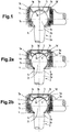
- the fully assembled ball joint shown in Fig. 1 includes a Articulated housing 1, which with a cylindrical bore 1a and ball-shaped bearing surface 1b is provided. At which the spherical ring-shaped bearing surface 1b adjoining the lower end Joint housing 1 has a passage opening 1c for a ball pin 2.
- the ball pin 2 includes a slightly conical in the embodiment Pin part 2a, which by means of an opposite conical transition 2b in a Bearing ball 2c merges.
- This bearing ball 2c is below its largest Diameter on the spherical ring-shaped bearing surface 1b of the joint housing 1 on.
- the bearing surface 1b is in one piece formed as part of the joint housing 1. In such an embodiment the bearing surface 1b is hardened, for example case hardened.
- This configuration of the cover 3 ensures that the cover 3 can be pressed into the joint housing 1 with a relatively low assembly force F 1 , which acts on the cover 3 not centrally but at a distance from the center of the cover, as shown by the lines of action in FIG 3 can be seen. Due to the design of the cover 3 and in particular the oblique edge region 3c, the edge region 3c bends elastically back against the pushing-in movement during assembly, so that the outer diameter of the cover 3, which is larger in the initial state, can be easily adapted to the smaller inner diameter, that is to say the bore 1 a of the joint housing 1 results.
- the pushing-in movement of the cover 3 is ended as soon as contact with the surface of the ball 2c has been reached and a predetermined pushing-in force F 1 has been reached.
- the cover 3 pressed into the joint housing 1 in this way now rests with its spherical bearing surface 3a against the ball 2c without play. In this way, all manufacturing tolerances can be compensated for when the cover assembly is completed.
- the deformed edge regions 3c of the cover 3 in the assembled state bring about a secure fixing of the cover edge on the joint housing 1, since the restoring forces present in this edge region tend to push the center region 3b of the cover 3 back out of the cylindrical bore 1a of the joint housing 1, the diameter increase required for this of the cover 3, however, is prevented by the contact of its edge region 3c in the cylindrical bore 1a of the joint housing 1. This results in a clamping force which holds the cover 3 securely in the cylindrical bore 1 a of the joint housing 1, despite the exclusively non-positive fixing.
- Fig. 1 represents a ball joint that only three components, namely the joint housing 1, the ball stud 2 with arranged ball 2 c and the lid 3 there.
- the spherical ring-shaped bearing surface 1b of the joint housing 1 not in one piece as part of the joint housing 1 formed, but on a separate part in the joint housing 1 arranged bearing shell 4 formed.
- the bearing shell 4 has a radial outwardly projecting edge 4a and ends in front of the passage opening 1c in the lower part of the joint housing 1.
- the as a separate part in the Articulated housing 1 insertable cups 4 can be made from any suitable Material, such as hardened steel, plastic or ceramic.
- FIG. 2a shows another difference arranged between cover 3 and surface of the ball 2c wear-preventing intermediate element 5.
- This intermediate element 5 after assembly is free of play between cover 3 and ball 2c.
- the intermediate elements 5 can act as a wear-preventing element centering the ball 2c in the radial direction when the radial occurred Wear caused by the fact that at the outer edge of the intermediate element 5 Centering lugs 5a are formed.
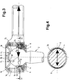
- Fig. 3 are the fourth embodiment of a ball joint various lines of force lines, for example, which at Assembly and occur when operating a ball joint.
- the fourth Embodiment corresponds essentially to that shown in Fig. 1 Embodiment, however, the bearing surface for the ball 2 is on as separate part in the joint housing 1 arranged bearing shell 4 is formed.
- FIG. 4 which represents a cross section through the ball 2c and the bearing shell 4 according to FIG. 3, the radial forces F R of such a ball joint, which is predominantly loaded in the radial direction, lead to crescent-shaped wear on the annular bearing surfaces 1b only in the radial direction to the direction of the longitudinal axis of the ball pin, that is to say that there is no play of the joint in the axial direction even when wear occurs.
- 5a to 5d is an example of the assembly of a ball joint and especially the lid assembly shown.
- To mount the cover 3 one consisting of a mounting mandrel 7a and a cover guide ring 7b Tool 7 used.
- the Cover 3 placed on the edge 1d of the joint housing 1 and that Tool 7 attached to the cover 3.
- the edge 1d With a chamfer 1e surrounding the cylindrical bore 1a.
- On the mounting mandrel 7a is also attached to its end face engaging on the cover 3 an annular pressure surface, which causes that not centrally, but in a ring at a distance from the center of the lid onto the lid 3 is pressed.
Landscapes
- Engineering & Computer Science (AREA)
- General Engineering & Computer Science (AREA)
- Mechanical Engineering (AREA)
- Pivots And Pivotal Connections (AREA)
- Joints Allowing Movement (AREA)
Abstract
Description
Die Erfindung betrifft ein Kugelgelenk, insbesondere als führendes Gelenk für Kraftfahrzeuge, mit einem eine kugelringförmige Lagerfläche aufweisenden Gelenkgehäuse, in dem eine an einem Kugelzapfen angeordnete Kugel begrenzt verdrehbar und kippbar gelagert ist und das durch einen Deckel verschlossen ist, der im Ausgangszustand mit einem den Innendurchmesser einer glattwandigen zylindrischen Bohrung des Gelenkgehäuses übersteigenden Außendurchmesser ausgebildet ist und der sich im Einbauzustand mit seinem Rand kraftschlüssig im Gelenkgehäuse abstützt. Weiterhin betrifft die Erfindung eine Vorrichtung zur Montage eines solchen Kugelgelenkes.The invention relates to a ball joint, in particular as a leading joint for Motor vehicles, with a spherical ring-shaped bearing surface Articulated housing in which a ball arranged on a ball pin limited rotatable and tiltable and that by a lid is closed, which in the initial state with an inner diameter a smooth-walled cylindrical bore of the joint housing Exceeding outer diameter is formed and the Installed state with its edge supported non-positively in the joint housing. Furthermore, the invention relates to a device for mounting such Ball joint.
Ein derartiges Kugelgelenk ist aus der DE-Patentschrift 195 13 826 bekannt. Durch die Verwendung des sich kraftschlüssig im Gelenkgehäuse abstützenden Deckels ist es bei diesem bekannten Kugelgelenk möglich, unter Vermeidung einer festen Anlagefläche für den Deckel Fertigungstoleranzen vollständig auszugleichen. Hierzu ist zwischen der Lagerkugel und dem Deckel ein Federelement angeordnet, das im Ausgangszustand definierte Federkräfte zur Verfügung stellt, um die verschleißbedingte Elastizität des Gelenks auszugleichen. Dieses Gelenk hat sich in dynamischen Versuchen zwar durchaus bewährt, jedoch wurde auf Grund von Berechnungen festgestellt, daß einerseits die Lebensdauer der Federelemente geringer ist als die Lebensdauer des Kugelgelenks und andererseits die ständige Belastung der Kugel in Richtung der Kugelzapfenlängsachse durch das Federelement unvermeidbar zu einem erhöhten Verschleiß der Lagerfläche in axialer Richtung führt. Hinzu kommt noch, daß auf Grund der ständigen Druckbelastung der Kugel in Richtung der Lagerfläche ungünstige Schmierbedingungen des üblicherweise mit einer Dauerschmierung versehenen Kugelgelenkes auftreten können.Such a ball joint is known from DE patent 195 13 826. By using the non-positive in the joint housing supporting lid, it is possible with this known ball joint Avoiding a fixed contact surface for the cover manufacturing tolerances completely compensate. For this is between the bearing ball and the cover a spring element is arranged, the spring forces defined in the initial state provides the wear-related elasticity of the joint balance. This joint has proven itself in dynamic tests well proven, but based on calculations it was found that on the one hand the life of the spring elements is less than that Lifetime of the ball joint and on the other hand the constant load on the Ball in the direction of the longitudinal axis of the ball pin through the spring element inevitable to increased wear of the bearing surface in the axial Direction leads. Add to that that due to the constant Unfavorable pressure load of the ball in the direction of the bearing surface Lubrication conditions of the one which is usually provided with permanent lubrication Ball joint can occur.
Ein weiteres Kugelgelenk mit einem sich kraftschlüssig im Gelenkgehäuse abstützenden Deckel ist aus der US-Patentschrift 4,163,617 bekannt. Bei diesem bekannten Kugelgelenk wird die Lagerfläche von einer mit axialen Schlitzen versehenen Schnappkapsel-Lagerschale gebildet, die die an dem Kugelzapfen angeordnete Kugel vollständig umschließt. Diese Schnappkapsel-Lagerschalen, welche ausschließlich aus Kunststoff herstellbar sind, weisen die Nachteile auf, daß einerseits materialbedingt eine großvolumige Bauart erforderlich ist und andererseits normale Kunststoffe nicht dafür geeignet sind, die insbesondere im Nutzfahrzeugbereich auftretenden hohen Belastungsspitzen ohne bleibende Beschädigungen der Lagerschale aufzunehmen.Another ball joint with a non-positive in the joint housing supporting cover is known from US Pat. No. 4,163,617. At this known ball joint is the bearing surface of one with axial Slotted snap-cup bearing shell formed that on the Ball pin completely encloses the arranged ball. These snap caps cups, which can only be manufactured from plastic the disadvantages that, on the one hand, due to the material, a large-volume design is required and on the other hand normal plastics are not suitable the high ones that occur particularly in the commercial vehicle sector Load peaks without permanent damage to the bearing shell to record.
Ausgehend von diesem Stand der Technik liegt der Erfindung die Aufgabe zugrunde, ein Kugelgelenk zu schaffen, das preiswert automatisiert herstellbar und bei geringem Verschleiß über lange Zeit funktionssicher ist. Weiterhin liegt der Erfindung die Aufgabe zugrunde, eine einfache Vorrichtung zur Montage eines solchen Kugelgelenkes zu schaffen.Based on this prior art, the invention has for its object to provide a ball joint that can be inexpensively automated and is reliable over a long period of time with little wear. Furthermore, the invention has for its object to provide a simple device for mounting such a ball joint.
Die Lösung dieser Aufgabe durch die Erfindung ist dadurch gekennzeichnet, daß der Deckel auf der der kugelringförmigen Lagerfläche des Gelenkgehäuses gegenüberliegenden Seite des Kugeläquators seinerseits mit einer kugelringförmigen Lagerfläche für die Kugel ausgebildet ist.The solution to this problem by the invention is characterized in that the cover is in turn formed on the side of the ball equator opposite the spherical bearing surface of the joint housing with a spherical bearing surface for the ball.
Durch die Ausbildung einer kugelringförmigen Lagerfläche am Deckel, der nicht durch Formschluß, das heißt unter Inkaufnahme von Fertigungstoleranzen, sondern kraftschlüssig, das heißt spielfrei montiert wird, kann eine Feder zwischen Deckel und einer separaten oberen Lagerschale entfallen. Da bei der erfindungsgemäßen Ausbildung des Kugelgelenkes keine in Achsrichtung wirkende Feder verwendet wird, ergibt sich nicht nur eine Verbilligung durch den Wegfall eines teuren Elements, sondern es entfällt auch der durch die zum Spielausgleich benötigte Feder hervorgerufene Verschleiß in axialer Richtung. Beim erfindungsgemäßen Gelenk, das insbesondere als führendes Gelenk eingesetzt und demzufolge überwiegend in radialer Richtung belastet wird, ergibt sich ein sichelförmiger Verschleiß an den kreisringförmigen Lagerflächen nur in der radial zur Kugelzapfenlängsachse verlaufenden Richtung, d. h. auch bei auftretendem Verschleiß entsteht kein relevantes Spiel in axialer Richtung.By forming a spherical bearing surface on the lid, the not by positive locking, that is, by accepting Manufacturing tolerances, but non-positively, that is, assembled without play, can have a spring between the cover and a separate upper bearing shell omitted. Since none in the inventive design of the ball joint axially acting spring is used, there is not only one Cheaper by the elimination of an expensive element, but it is also eliminated the wear caused by the spring required to compensate for play axial direction. In the joint according to the invention, which in particular as leading joint used and therefore mainly in the radial direction is loaded, there is a crescent-shaped wear on the circular bearing surfaces only in the radial to the longitudinal axis of the ball stud direction, d. H. there is also no wear relevant play in the axial direction.
Die kugelringförmige Lagerfläche des Deckels liegt entweder unmittelbar oder mittelbar an der Kugeloberfläche an, d. h. ohne zwischengeschaltete Feder aus elastisch federndem oder elastisch verformbarem Material. Durch diese Einsparung eines Bauteils wird die Montage des erfindungsgemäßen Kugelgelenkes vereinfacht und somit preiswerter. Die geforderte Funktionssicherheit ergibt sich bei dem solchermaßen ausgestalteten Kugelgelenk dadurch, daß die bei der Herstellung unvermeidlichen Toleranzen durch den sich kraftschlüssig im Gelenkgehäuse abstützenden Deckel bei der Montage auf einfache Weise ausgeglichen werden.The spherical ring-shaped bearing surface of the cover is either immediate or indirectly on the surface of the sphere, d. H. without intermediate spring made of resilient or resilient material. Through this Saving a component is the assembly of the invention Ball joint simplified and therefore cheaper. The required Functional reliability results in the case of such a design Ball joint in that the inevitable tolerances in the manufacture through the non-positively supported cover in the joint housing Assembly can be easily compensated.
Gemäß einer ersten Ausführungsform der Erfindung ist die Lagerfläche zur Lagerung der an dem Kugelzapfen angeordneten Kugel einstückig als Teil des Gelenkgehäuses ausgebildet. Bei dieser Ausführungsform, bei der das Gehäuse im Bereich der kugelringförmigen Lagerfläche gehärtet ist, besteht die gesamte, das Kugelgelenk bildende Baugruppe aus nur drei Bauteilen, nämlich dem Gelenkgehäuse, dem Kugelzapfen mit angeordneter Kugel sowie dem Deckel zum Verschließen des Gelenkgehäuses. Auf Grund der Beschränkung der Bauteilzahl auf das Minimum, ist ein solchermaßen aufgebautes Kugelgelenk äußerst einfach und preiswert zu fertigen.According to a first embodiment of the invention, the bearing surface is Storage of the ball arranged on the ball pin in one piece as part of the Articulated housing trained. In this embodiment, in which the Housing is hardened in the area of the spherical bearing surface the entire assembly, which forms the ball joint, from only three components, namely the joint housing, the ball pin with an arranged ball and the cover for closing the joint housing. Due to the Limiting the number of components to the minimum is one of them assembled ball joint extremely easy and inexpensive to manufacture.
Bei einer zweiten Ausführungsform eines erfindungsgemäßen Kugelgelenkes ist die Lagerfläche an einer als separates Teil im Gehäuse angeordneten Lagerschale ausgebildet. Diese Ausführungsform ermöglicht auf einfache Weise eine Anpassung der Lagerfläche des Kugelgelenkes an verschiedene Einsatzbedingungen. Durch geeignete Wahl des Materials der Lagerschale, beispielsweise gehärtetes Metall, Kunststoff oder Keramik ist eine solche Anpassung des Kugelgelenkes auf einfache Weise möglich.In a second embodiment of a ball joint according to the invention the bearing surface is arranged on a separate part in the housing Bearing shell formed. This embodiment allows for simple Way an adjustment of the bearing surface of the ball joint to different Operating conditions. By suitable choice of the material of the bearing shell, for example hardened metal, plastic or ceramic is one Adjustment of the ball joint possible in a simple way.
Um einem Verschleiß der an dem Deckel ausgebildeten kugelringförmigen Lagerfläche für die Kugel entgegenzuwirken, wird gemäß einer bevorzugten Ausführungsform der Erfindung vorgeschlagen, daß der Deckel zumindest im Bereich seiner kugelringförmigen Lagerfläche verschleißgeschützt ist. Bei einem aus Stahl gefertigten Deckel bedeutet dies, daß dieser zumindest im Bereich der kugelringförmigen Lagerfläche gehärtet, beispielsweise einsatzgehärtet ist. Bei aus Kunststoff gefertigten Deckeln ist eine Armierung des Kunststoffmaterials, beispielsweise durch Eisen oder durch Ausbilden eines Kunststoff-Kompositwerkstoffs vorteilhaft. Ebenso ist es möglich, den Deckel zumindest teilweise mit einer kugelringförmigen Lagerfläche aus Keramik auszubilden.To wear the spherical ring-shaped on the lid Counteracting bearing surface for the ball is preferred according to one Embodiment of the invention proposed that the lid at least in Area of its spherical bearing surface is protected against wear. At a lid made of steel, this means that this at least in Hardened area of the spherical bearing surface, for example is case hardened. In the case of lids made of plastic, there is reinforcement of the plastic material, for example by iron or by training a plastic composite material advantageous. It is also possible to Lid at least partially with a spherical bearing surface To train ceramics.
Gemäß einer weiteren Ausführungsform der Erfindung wird vorgeschlagen, daß zumindest im Bereich der kugelringförmigen Lagerfläche des Deckels ein verschleißverhinderndes Zwischenelement angeordnet ist. Bei dieser Ausführungsform, bei der nach der Montage keinerlei Spiel zwischen Deckel und Zwischenelement besteht, erfolgt der Verschleißschutz der kugelringförmigen Lagerfläche des Deckels über ein separates verschleißverhinderndes Zwischenelement, so daß die kugelringförmige Lagerfläche des Deckels nur mittelbar an der Kugeloberfläche anliegt.According to a further embodiment of the invention, it is proposed that that at least in the area of the spherical bearing surface of the lid wear-preventing intermediate element is arranged. At this Embodiment in which there is no play between the lid after assembly and there is an intermediate element, the wear protection takes place spherical bearing surface of the cover via a separate wear-preventing intermediate element, so that the spherical ring The bearing surface of the cover is only in indirect contact with the spherical surface.
Eine Zentrierung der Kugel in radialer Richtung bei aufgetretenem radialen Verschleiß kann gemäß einer weiteren Ausführungsform der Erfindung dadurch bewirkt werden, daß am äußeren Rand eines zwischen Deckel und Kugeloberfläche angeordneten Zwischenelements Zentrieransätze ausgebildet sind, die sich am Deckel und/oder Gelenkgehäuse abstützen. Durch die spielfreie Anordnung dieser Zwischenelemente auf der Gehäuseinnenseite des Deckels können die Zwischenelemente keine Federwirkung in axialer Richtung ausüben, wie dies aus dem Stand der Technik bekannt ist.A centering of the ball in the radial direction when the radial occurred Wear can occur according to a further embodiment of the invention are caused by the fact that on the outer edge of a between cover and Spherical surface arranged intermediate element formed centering approaches are supported on the cover and / or joint housing. Through the play-free arrangement of these intermediate elements on the inside of the housing Cover, the intermediate elements have no spring action in the axial direction exercise as is known in the art.
Um das Einsetzen des Deckels bei der Montage zu erleichtern, ist gemäß einer bevorzugten Ausführungsform der Erfindung das Gelenkgehäuse mit einer die zylindrische Bohrung umgebende Anfasung versehen.In order to facilitate the insertion of the cover during assembly, according to one preferred embodiment of the invention, the joint housing with a chamfer surrounding cylindrical bore.
Schließlich wird mit der Erfindung vorgeschlagen, daß der Rand des Gehäuses nach Abschluß der Montage des Deckels zur formschlüssigen Festlegung des Deckels umgeformt ist. Diese formschlüssige Festlegung des Deckels erfolgt ohne Veränderung der vorherigen Lagepositionierung des Deckels und beeinflußt somit in keiner Weise die axiale Belastung der Kugel durch den Deckel.Finally, the invention proposes that the edge of the housing after completing the assembly of the cover for the positive determination of the Lid is formed. This form-fitting fixing of the lid takes place without changing the previous position of the cover and thus in no way affects the axial loading of the ball by the Cover.
Die Vorrichtung zur Montage eines erfindungsgemäßen Kugelgelenkes ist gekennzeichnet durch einen den Deckel in das Gelenkgehäuse eindrückenden Montagedorn, der an seiner Stirnfläche mit einer kreisringförmigen, am Deckel anliegenden Druckfläche ausgebildet ist. Durch die Ausbildung dieser kreisringförmigen Druckfläche wird bewirkt, daß nicht zentral, sondern im Abstand vom Deckelmittelpunkt auf den Deckel gedrückt wird, so daß der Deckel nur mit der späteren kugelringförmigen Lagerfläche an der Kugel anliegt.The device for mounting a ball joint according to the invention is characterized by a pushing the cover into the joint housing Assembly mandrel, which on its end face with an annular, on the lid adjacent pressure surface is formed. By training this circular pressure surface is caused not in the center, but in Distance from the center of the lid is pressed onto the lid, so that the Cover only with the later spherical bearing surface on the ball is present.
Weiterhin wird mit der Erfindung vorgeschlagen, auf dem Montagedorn einen Deckelführungsring anzuordnen. Die Verwendung eines solchen Deckelführungsrings hat sich als vorteilhaft erwiesen, da hierdurch ein Kippen des Deckels bei der Montage verhindert werden kann. Da das Eindrücken des Deckels in das Gelenkgehäuse nur über den Montagedorn erfolgt, weist der Deckelführungsring normalerweise ein geringes Spiel zum Deckelrand auf.Furthermore, the invention proposes a on the mounting mandrel To arrange the cover guide ring. The use of such The cover guide ring has proven to be advantageous because it tilts it of the lid can be prevented during assembly. Since the impression of the The cover in the joint housing only takes place via the assembly mandrel The lid guide ring normally has a slight clearance to the edge of the lid.
Weitere Merkmale und Vorteile der Erfindung ergeben sich aus der nachfolgenden Beschreibung der zugehörigen Zeichnung, in der vier Ausführungsbeispiele eines erfindungsgemäßen Kugelgelenkes sowie ein Ausführungsbeispiel einer Vorrichtung zur Montage eines erfindungsgemäßen Kugelgelenkes dargestellt ist. In der Zeichnung zeigt:
- Fig. 1
- einen Längsschnitt durch eine erste Ausführungsform eines Kugelgelenkes;
- Fig. 2a
- einen Längsschnitt durch eine zweite Ausführungsform eines Kugelgelenkes;
- Fig. 2b
- einen Längsschnitt durch eine dritte Ausführungsform eines Kugelgelenkes;
- Fig. 3
- einen Längsschnitt durch eine vierte Ausführungsform eines Kugelgelenkes mit eingezeichneten Kraftwirkungslinien;
- Fig. 4
- einen Querschnitt entlang der Schnittlinie IV-IV in Fig. 3 und
- Fig. 5a bis 5d
- einen schematischen Montageablauf zur Herstellung eines Kugelgelenkes gemäß Fig. 3.
- Fig. 1
- a longitudinal section through a first embodiment of a ball joint;
- Fig. 2a
- a longitudinal section through a second embodiment of a ball joint;
- Fig. 2b
- a longitudinal section through a third embodiment of a ball joint;
- Fig. 3
- a longitudinal section through a fourth embodiment of a ball joint with drawn lines of action;
- Fig. 4
- a cross section along the section line IV-IV in Fig. 3 and
- 5a to 5d
- 3 shows a schematic assembly process for producing a ball joint according to FIG. 3.
Das in Fig. 1 fertig montiert dargestellte Kugelgelenk umfaßt ein
Gelenkgehäuse 1, das mit einer zylindrischen Bohrung 1a und einer
kugelringförmigen Lagerfläche 1b versehen ist. An dem sich an die
kugelringförmige Lagerfläche 1b anschließenden unteren Ende weist das
Gelenkgehäuse 1 eine Durchtrittsöffnung 1c für einen Kugelzapfen 2 auf.The fully assembled ball joint shown in Fig. 1 includes a
Articulated
Der Kugelzapfen 2 umfaßt beim Ausführungsbeispiel einen leicht konischen
Zapfenteil 2a, der mittels eines gegenläufig konischen Übergangs 2b in eine
Lagerkugel 2c übergeht. Diese Lagerkugel 2c liegt unterhalb ihres größten
Durchmessers an der kugelringförmigen Lagerfläche 1b des Gelenkgehäuses 1
an. Beim dargestellten Ausführungsbeispiel ist die Lagerfläche 1b einstückig
als Teil des Gelenkgehäuses 1 ausgebildet. Bei einer solchen Ausführungsform
ist die Lagerfläche 1b gehärtet, beispielsweise einsatzgehärtet.The
Im montierten Zustand, wie dieser in den Abbildungen Fig. 1 bis 3 dargestellt
ist, ist die zylindrische Bohrung 1a des Gelenkgehäuses 1 durch einen Deckel
3 verschlossen, der auf der der kugelringförmigen Lagerfläche 1b des
Gelenkgehäuses 1 gegenüberliegenden Seite des Kugeläquators seinerseits
eine kugelringförmige Lagerfläche 3a für die Kugel 2c bildend an der Kugel 2c
anliegt. Wie aus den Abbildungen ersichtlich, ist der Deckel 3 im Querschnitt
W-förmig so ausgebildet, daß er nur mit der kugelringförmigen Lagerfläche 3a
an der Kugel 2c anliegt, während ein Mittenbereich 3b des Deckels 3 so nach
oben gebogen ist, daß dieser Mittenbereich 3b im montierten Zustand des
Deckels nicht an der Kugel 2c anliegt. Von den Lagerflächen 3a aus geht der
Deckel 3 in einen schräg nach oben verlaufenden Randbereich 3c über.In the assembled state, as shown in Figures 1 to 3
is, the
Durch diese Ausgestaltung des Deckels 3 wird erreicht, daß der Deckel 3 mit
einer verhältnismäßig geringen Montagekraft F1, die nicht zentral, sondern im
Abstand vom Deckelmittelpunkt auf den Deckel 3 wirkt, in das Gelenkgehäuse
1 eingedrückt werden kann, wie dies den Kraftwirkungslinien in Fig. 3 zu
entnehmen ist. Aufgrund der Ausgestaltung des Deckels 3 und insbesondere
des schrägen Randbereiches 3c biegt sich bei der Montage der Randbereich
3c entgegen der Eindrückbewegung elastisch zurück, so daß sich auf einfache
Weise eine Anpassung des im Ausgangszustand größeren Außendurchmessers
des Deckels 3 an den kleineren Innendurchmesser, das heißt an die Bohrung
1 a des Gelenkgehäuses 1 ergibt. Die Eindrückbewegung des Deckels 3 ist
beendet, sobald ein Kontakt mit der Oberfläche der Kugel 2c erreicht und eine
vorgegebene Eindrückkraft F1 erreicht worden ist. Der solchermaßen in das
Gelenkgehäuse 1 eingedrückte Deckel 3 liegt nunmehr spielfrei mit seiner
kugelringförmigen Lagerfläche 3a an der Kugel 2c an. Auf diese Weise können
sämtliche Herstellungstoleranzen bei Abschluß der Deckelmontage
ausgeglichen werden. Die verformten Randbereiche 3c des Deckels 3 im
montierten Zustand bewirken eine sichere Festlegung des Deckelrandes am
Gelenkgehäuse 1, da die in diesem Randbereich vorhandenen Rückstellkräfte
dazu tendieren, den Mittenbereich 3b des Deckels 3 aus der zylindrischen
Bohrung 1a des Gelenkgehäuses 1 zurückzudrücken, die hierfür erforderliche
Durchmesservergrößerung des Deckels 3 jedoch durch die Anlage seines
Randbereiches 3c in der zylindrischen Bohrung 1a des Gelenkgehäuses 1
verhindert wird. Es ergibt sich auf diese Weise eine Klemmkraft, die den
Deckel 3 trotz der ausschließlich kraftschlüssigen Festlegung sicher in der
zylindrischen Bohrung 1a des Gelenkgehäuses 1 hält.This configuration of the
Die in Fig. 1 dargestellte Ausführungsform stellt ein Kugelgelenk dar, das aus
nur drei Bauteilen, nämlich dem Gelenkgehäuse 1, dem Kugelzapfen 2 mit
angeordneter Kugel 2c sowie dem Deckel 3 besteht.The embodiment shown in Fig. 1 represents a ball joint that
only three components, namely the
Bei der in Fig. 2a dargestellten zweiten Ausführungsform eines Kugelgelenkes
ist im Gegensatz zur ersten Ausführungsform die kugelringförmige Lagerfläche
1b des Gelenkgehäuses 1 nicht einstückig als Teil des Gelenkgehäuses 1
ausgebildet, sondern an einer als separates Teil im Gelenkgehäuse 1
angeordneten Lagerschale 4 ausgebildet. Die Lagerschale 4 weist einen radial
nach außen abstehenden Rand 4a auf und endet vor der Durchtrittsöffnung 1c
im unteren Teil des Gelenkgehäuses 1. Die als separates Teil in das
Gelenkgehäuse 1 einsetzbaren Lagerschalen 4 können aus jedem geeigneten
Material, beispielsweise gehärtetem Stahl, Kunststoff oder Keramik bestehen. In the second embodiment of a ball joint shown in FIG. 2a
is in contrast to the first embodiment, the spherical ring-shaped
Als weiteren Unterschied weist die in Fig. 2a dargestellte Ausführungsform ein
zwischen Deckel 3 und Oberfläche der Kugel 2c angeordnetes
verschleißverhinderndes Zwischenelement 5 auf. Dieses Zwischenelement 5
liegt nach der Montage spielfrei zwischen Deckel 3 und Kugel 2c. Neben der
Wirkung als verschleißverhinderndes Element können die Zwischenelemente 5
eine Zentrierung der Kugel 2c in radialer Richtung bei aufgetretenem radialen
Verschleiß dadurch bewirken, daß am äußeren Rand des Zwischenelementes 5
Zentrieransätze 5a angeformt sind. Bei dem in Fig. 2a dargestellten
Ausführungsbeispiel stützen sich die Zentrieransätze 5a des
Zwischenelementes 5 an der Unterseite des Deckels 3 ab.The embodiment shown in FIG. 2a shows another difference
arranged between
Bei der in Fig. 2b dargestellten dritten Ausführungsform eines Kugelgelenkes
stützen sich die Zentrieransätze 5a des Zwischenelementes 5 am
Gelenkgehäuse 1, und zwar an der zylindrischen Bohrung 1a des
Gelenkgehäuses 1 ab. Ansonsten entspricht die Ausgestaltung der
Ausführungsform gemäß Fig. 2b der Ausführungsform gemäß Fig. 2a.In the third embodiment of a ball joint shown in FIG. 2b
the centering
Aus den Abbildungen Fig. 2a und 2b ist weiterhin ersichtlich, daß ein oberer
Rand 1d des Gelenkgehäuses 1 nach Abschluß der Montage des Deckels 3 zur
formschlüssigen Festlegung des Deckels 3 umgeformt werden kann. Diese
Umformung des Randes 1d bewirkt keine Veränderung der Lagepositionierung
des Deckels in der zylindrischen Bohrung 1a.From Figures 2a and 2b it can also be seen that an
In Fig. 3 sind bei einer vierten Ausführungsform eines Kugelgelenkes die
verschiedenen Kraftwirkungslinien beispielhaft eingezeichnet, die bei der
Montage und beim Betrieb eines Kugelgelenkes auftreten. Die vierte
Ausführungsform entspricht im wesentlichen der in Fig. 1 dargestellten
Ausführungsform, jedoch ist die Lagerfläche für die Kugel 2 an einer als
separates Teil im Gelenkgehäuse 1 angeordneten Lagerschale 4 ausgebildet.In Fig. 3 are the fourth embodiment of a ball joint
various lines of force lines, for example, which at
Assembly and occur when operating a ball joint. The fourth
Embodiment corresponds essentially to that shown in Fig. 1
Embodiment, however, the bearing surface for the
Wie aus der Darstellung ersichtlich, kann die Krafteinleitung im Fahrbetrieb FB
in eine Radialkraftkomponente FR und eine Axialkraftkomponente FA zerlegt
werden. Da die dargestellten Kugelgelenke insbesondere als führende Gelenke
eingesetzt und demzufolge überwiegend in radialer Richtung belastet werden,
stellt die Radialkraftkomponente FR die Hauptkraftkomponente dar.
Demzufolge tritt auch in Radialrichtung der Hauptverschleiß solcher
Kugelgelenke auf. Solche Hauptverschleißzonen 6 liegen knapp unterhalb des
Äquators der Kugel 2c, wie dies in Fig. 3 dargestellt ist.As can be seen from the illustration, the introduction of force when driving F B can be broken down into a radial force component F R and an axial force component F A. Since the ball joints shown are used in particular as leading joints and are therefore predominantly loaded in the radial direction, the radial force component F R is the main force component. Accordingly, the main wear of such ball joints also occurs in the radial direction. Such
Wie aus Fig. 4 ersichtlich, die einen Querschnitt durch die Kugel 2c und die
Lagerschale 4 gemäß Fig. 3 darstellt, führen die Radialkräfte FR eines solchen
überwiegend in radialer Richtung belasteten Kugelgelenks zu einem
sichelförmigen Verschleiß an den kreisringförmigen Lagerflächen 1b nur in der
radial zur Kugelzapfenlängsachse verlaufenden Richtung, das heißt, daß auch
bei auftretendem Verschleiß kein Spiel des Gelenks in axialer Richtung
entsteht.As can be seen from FIG. 4, which represents a cross section through the
In Fig. 5a bis 5d ist beispielhaft die Montage eines Kugelgelenks und
insbesondere die Deckelmontage dargestellt. Zur Montage des Deckels 3 wird
ein aus einem Montagedorn 7a und einem Deckelführungsring 7b bestehendes
Werkzeug 7 verwendet.5a to 5d is an example of the assembly of a ball joint and
especially the lid assembly shown. To mount the
Bei dem in Fig. 5a dargestellten ersten Montageschritt wird zunächst der
Deckel 3 auf den Rand 1d des Gelenkgehäuses 1 aufgesetzt und das
Werkzeug 7 am Deckel 3 angesetzt. Um das Einführen des Deckels 3 in die
zylindrische Bohrung 1a des Gelenkgehäuses 1 zu erleichtern, ist der Rand 1d
mit einer die zylindrische Bohrung 1a umgebenden Anfasung 1e versehen. An
seiner an dem Deckel 3 angreifenden Stirnfläche ist der Montagedorn 7a mit
einer kreisringförmigen Druckfläche ausgebildet, die bewirkt, daß nicht zentral,
sondern ringförmig im Abstand vom Deckelmittelpunkt auf den Deckel 3
gedrückt wird.In the first assembly step shown in FIG. 5a, the
Bei der in den Abbildungen 5b und 5c dargestellten weiteren Montage wird
der Deckel 3 über den Montagedorn 7a in die zylindrische Bohrung 1a des
Gelenkgehäuses 1 eingedrückt, bis der Deckel 3 in Kontakt mit der Oberfläche
der Kugel 2 tritt. Das Eindrücken des Deckels 3 über den Montagedorn 7a
wird beim Erreichen einer vorgebbaren Eindrückkraft beendet. Der auf dem
Montagedorn 7a angeordnete Deckelführungsring 7b verhindert ein Kippen
des Deckels 3 bei der Montage. Da über den Deckelführungsring 7b keine
Druckkräfte auf den Deckel 3 ausgeübt werden, hat der Deckelführungsring
7b normalerweise geringes Spiel zu den Randbereichen 3c des Deckels 3.
Nach Beendigung der Deckelmontage wird das Werkzeug 7 wieder vom
Deckel 3 fortgefahren, wie dies in Fig. 5d dargestellt ist. Beim Abziehen des
Werkzeuges 7 biegt sich der Mittenbereich 3b des Deckels 3 wieder aufwärts,
so daß der Deckel 3 nur mit seiner kugelringförmigen Lagerfläche 3a an der
Kugel 2c anliegt. Durch das Fortlassen eines das Kugelgelenk in axialer
Richtung vorspannende Federelements kann ein solchermaßen ausgestaltetes
Kugelgelenk besonders einfach und preiswert auch in der automatisierten
Serienfertigung funktionssicher hergestellt werden. In the further assembly shown in Figures 5b and 5c
the
- 11
- GelenkgehäuseJoint housing
- 1a1a
- Bohrungdrilling
- 1b1b
- Lagerflächestorage area
- 1c1c
- DurchtrittsöffnungPassage opening
- 1d1d
- Randedge
- 1e1e
- AnfasungChamfer
- 22nd
- KugelzapfenBall stud
- 2a2a
- ZapfenteilCone part
- 2b2 B
- Übergangcrossing
- 2c2c
- KugelBullet
- 33rd
- Deckelcover
- 3a3a
- Lagerflächestorage area
- 3b3b
- MittenbereichMiddle area
- 3c3c
- RandbereichEdge area
- 44th
- LagerschaleBearing shell
- 4a4a
- Rand edge
- 55
- ZwischenelementIntermediate element
- 5a5a
- ZentrieransatzCentering approach
- 66
- HauptverschleißzoneMain wear zone
- 77
- WerkzeugTool
- 7a7a
- MontagedornAssembly mandrel
- 7b7b
- DeckelführungsringLid guide ring
- F1 F 1
- DeckelmontagekraftLid assembly force
- FB F B
- FahrbetriebskraftDriving force
- FR F R
- RadialkraftRadial force
- FA F A
- AxialkraftAxial force
Claims (10)
dadurch gekennzeichnet,
daß der Deckel (3) auf der der kugelringförmigen Lagerfläche (1b) des Gelenkgehäuses (1) gegenüberliegenden Seite des Kugeläquators seinerseits mit einer kugelringförmigen Lagerfläche (3a) für die Kugel (2c) ausgebildet ist.Ball joint, in particular as a leading joint for motor vehicles, with a joint housing (1) with a spherical bearing surface (1b), in which a ball (2c) arranged on a ball pin (2) is rotatably and tiltably supported and which is supported by a cover (3 ) is closed, which in the initial state is designed with an outer diameter exceeding the inside diameter of a smooth-walled cylindrical bore (1a) of the joint housing (1) and which is non-positively supported in the joint housing (1) with its edge (3c) in the installed state,
characterized by
that the cover (3) is in turn formed on the side of the ball equator opposite the spherical bearing surface (1b) of the joint housing (1) with a spherical bearing surface (3a) for the ball (2c).
Applications Claiming Priority (2)
| Application Number | Priority Date | Filing Date | Title |
|---|---|---|---|
| DE19638466 | 1996-09-19 | ||
| DE19638466A DE19638466C1 (en) | 1996-09-19 | 1996-09-19 | Ball joints and device for mounting a ball joint |
Publications (2)
| Publication Number | Publication Date |
|---|---|
| EP0836018A1 true EP0836018A1 (en) | 1998-04-15 |
| EP0836018B1 EP0836018B1 (en) | 2003-03-12 |
Family
ID=7806267
Family Applications (1)
| Application Number | Title | Priority Date | Filing Date |
|---|---|---|---|
| EP97115854A Expired - Lifetime EP0836018B1 (en) | 1996-09-19 | 1997-09-12 | Ball joint and method of mounting |
Country Status (6)
| Country | Link |
|---|---|
| US (1) | US6030141A (en) |
| EP (1) | EP0836018B1 (en) |
| JP (1) | JP2000500851A (en) |
| DE (2) | DE19638466C1 (en) |
| ES (1) | ES2195062T3 (en) |
| WO (1) | WO1998012439A1 (en) |
Cited By (1)
| Publication number | Priority date | Publication date | Assignee | Title |
|---|---|---|---|---|
| WO2007115515A1 (en) * | 2006-03-20 | 2007-10-18 | Zf Friedrichshafen Ag | Joint and/or bearing arrangement |
Families Citing this family (20)
| Publication number | Priority date | Publication date | Assignee | Title |
|---|---|---|---|---|
| US6382865B1 (en) * | 1999-06-21 | 2002-05-07 | Richard C. Paxman | Base-mounted lubricated ball joint |
| DE10130758B4 (en) * | 2001-06-19 | 2005-11-03 | Alfred Heyd Gmbh U. Co. | ball joint |
| US6619873B2 (en) * | 2001-09-06 | 2003-09-16 | Federal-Mogul World Wide, Inc. | Device and method for closing movable socket assemblies by expanding solid cover plates |
| US6875388B2 (en) | 2001-11-07 | 2005-04-05 | Illinois Tool Works Inc. | Method for making a ball and socket joint |
| US20030086756A1 (en) * | 2001-11-07 | 2003-05-08 | Trotter Jason K | Modular linkage system |
| US6929271B2 (en) | 2001-11-09 | 2005-08-16 | Illinois Tool Works Inc. | Hydraulically compensated stabilizer system |
| DE10314902C5 (en) * | 2003-04-01 | 2010-09-23 | ZF Lemförder GmbH | Ball joint with sealing bellows |
| TWM256036U (en) * | 2004-03-22 | 2005-01-21 | Global Target Entpr Inc | Adjustable bluetooth wireless earphone |
| DE202004012604U1 (en) * | 2004-08-11 | 2004-12-23 | Trw Automotive Gmbh | ball joint |
| DE102005028515A1 (en) * | 2005-06-17 | 2006-12-28 | Zf Friedrichshafen Ag | ball joint |
| KR100816381B1 (en) * | 2006-12-22 | 2008-03-25 | 주식회사 만도 | Vehicle steering apparatus including tie rod and ball seat equipped with the function for preventing deflection |
| KR100834211B1 (en) * | 2007-02-05 | 2008-05-30 | 위아 주식회사 | Apparatus for fixing ball stud of ball joint |
| DE112009002598B4 (en) * | 2008-11-12 | 2017-06-01 | Borgwarner Inc. | Coupling rod of a turbocharger |
| KR20110063164A (en) * | 2009-12-04 | 2011-06-10 | 현대자동차주식회사 | Suspension arm |
| DE102011118852A1 (en) * | 2011-11-18 | 2013-05-23 | Benteler Automobiltechnik Gmbh | Ball-and-socket joint for use in landing gear of motor vehicle, has bearing fixed in housing, and pin connected with bearing ball and projecting from housing, where bearing comprises two ceramic elements that are designed as ball zones |
| FR3016940B1 (en) * | 2014-01-29 | 2016-12-02 | Jtekt Europe Sas | USE OF A BALL JOINT CUTTER AS A GAME RETRACTOR |
| DE102016206864A1 (en) * | 2016-04-22 | 2017-10-26 | Zf Friedrichshafen Ag | Ball joint, in particular for a chassis of a motor vehicle, and method for mounting such a ball joint |
| DE102016206863A1 (en) * | 2016-04-22 | 2017-10-26 | Zf Friedrichshafen Ag | Axial ball joint and adjustable length two-point link with such an axial ball joint |
| CN111148911B (en) | 2017-08-16 | 2022-03-29 | 多媒体股份有限公司 | Ball joint with injection molded bearing |
| US11708852B2 (en) * | 2021-06-27 | 2023-07-25 | Federal-Mogul Motorspots Llc | Ball joint, method of manufacturing a ball joint, and tool for manufacturing a ball joint |
Citations (6)
| Publication number | Priority date | Publication date | Assignee | Title |
|---|---|---|---|---|
| FR1171068A (en) * | 1957-02-15 | 1959-01-22 | Ehrenreich & Cie A | Ball joint, in particular for steering linkages of motor vehicles |
| GB917866A (en) * | 1958-11-25 | 1963-02-06 | Automotive Prod Co Ltd | Improvements in or relating to ball-and-socket joints |
| FR2075134A5 (en) * | 1970-01-20 | 1971-10-08 | Trw Inc | |
| US4163617A (en) | 1977-02-14 | 1979-08-07 | Musashisemitsukoguo Kabushikikaisha | Ball joint |
| FR2503291A1 (en) * | 1981-04-06 | 1982-10-08 | Gulf & Western Mfg Co | BALL JOINT |
| DE19513826C1 (en) | 1995-04-12 | 1996-07-04 | Trw Fahrwerksyst Gmbh & Co | Ball-and-socket joint for utility vehicles |
Family Cites Families (7)
| Publication number | Priority date | Publication date | Assignee | Title |
|---|---|---|---|---|
| US3571880A (en) * | 1969-04-07 | 1971-03-23 | Columbus Auto Parts Co The | Method of assembling pivot joints |
| US3656221A (en) * | 1970-02-02 | 1972-04-18 | Moog Industries Inc | Method of assembly of joint devices and apparatus therefor |
| JPS4910780B1 (en) * | 1970-10-13 | 1974-03-13 | ||
| DE2210351A1 (en) * | 1971-03-05 | 1972-09-21 | Ishikawa Tekko Kk | Ball joint |
| US4283833A (en) * | 1979-03-16 | 1981-08-18 | The Bendix Corporation | Method of attaching a ball joint to a suspension member |
| DE3315718C2 (en) * | 1983-04-29 | 1986-06-26 | Lemförder Metallwaren AG, 2844 Lemförde | Ball joint for particularly heavily loaded joint linkages in motor vehicles |
| DE9304897U1 (en) * | 1993-03-31 | 1993-06-03 | P.C. Turck Gmbh & Co. Kg, 5880 Luedenscheid, De |
-
1996
- 1996-09-19 DE DE19638466A patent/DE19638466C1/en not_active Expired - Fee Related
-
1997
- 1997-09-12 ES ES97115854T patent/ES2195062T3/en not_active Expired - Lifetime
- 1997-09-12 EP EP97115854A patent/EP0836018B1/en not_active Expired - Lifetime
- 1997-09-12 DE DE59709475T patent/DE59709475D1/en not_active Expired - Fee Related
- 1997-09-16 US US09/068,711 patent/US6030141A/en not_active Expired - Fee Related
- 1997-09-16 WO PCT/EP1997/005059 patent/WO1998012439A1/en active Application Filing
- 1997-09-16 JP JP10514279A patent/JP2000500851A/en not_active Ceased
Patent Citations (6)
| Publication number | Priority date | Publication date | Assignee | Title |
|---|---|---|---|---|
| FR1171068A (en) * | 1957-02-15 | 1959-01-22 | Ehrenreich & Cie A | Ball joint, in particular for steering linkages of motor vehicles |
| GB917866A (en) * | 1958-11-25 | 1963-02-06 | Automotive Prod Co Ltd | Improvements in or relating to ball-and-socket joints |
| FR2075134A5 (en) * | 1970-01-20 | 1971-10-08 | Trw Inc | |
| US4163617A (en) | 1977-02-14 | 1979-08-07 | Musashisemitsukoguo Kabushikikaisha | Ball joint |
| FR2503291A1 (en) * | 1981-04-06 | 1982-10-08 | Gulf & Western Mfg Co | BALL JOINT |
| DE19513826C1 (en) | 1995-04-12 | 1996-07-04 | Trw Fahrwerksyst Gmbh & Co | Ball-and-socket joint for utility vehicles |
Cited By (1)
| Publication number | Priority date | Publication date | Assignee | Title |
|---|---|---|---|---|
| WO2007115515A1 (en) * | 2006-03-20 | 2007-10-18 | Zf Friedrichshafen Ag | Joint and/or bearing arrangement |
Also Published As
| Publication number | Publication date |
|---|---|
| EP0836018B1 (en) | 2003-03-12 |
| US6030141A (en) | 2000-02-29 |
| DE59709475D1 (en) | 2003-04-17 |
| DE19638466C1 (en) | 1998-03-26 |
| ES2195062T3 (en) | 2003-12-01 |
| WO1998012439A1 (en) | 1998-03-26 |
| JP2000500851A (en) | 2000-01-25 |
Similar Documents
| Publication | Publication Date | Title |
|---|---|---|
| EP0836018B1 (en) | Ball joint and method of mounting | |
| EP0766029B1 (en) | Solenoid valve and manufacturing process | |
| DE10060638B4 (en) | wheel bearing unit | |
| DE4209835B4 (en) | ball joint | |
| EP1778988B1 (en) | Ball joint | |
| EP0513562A1 (en) | Transporting device | |
| EP0737820B1 (en) | Ball-joint | |
| DE2451084A1 (en) | BALL JOINT | |
| EP0922868A2 (en) | Ball joint | |
| DE112019003571T5 (en) | BALL SOCKET ASSEMBLY WITH PRESSED COVER PLATE AND METHOD FOR MANUFACTURING IT | |
| DE4108827C2 (en) | ||
| EP0924441A1 (en) | Ball joint and procedure to bias it | |
| EP0559652B1 (en) | Ball stop for maintaining a control component in position, especially a shift linkage for motor vehicles | |
| EP1474615B2 (en) | Elastomer articulation | |
| DE4204630C2 (en) | Ball catch for fixing the position of a movable control element | |
| DE69931693T2 (en) | Holder for a constant velocity joint | |
| DE102004058963A1 (en) | Timing pulley | |
| EP0732645A1 (en) | Detent bolt | |
| WO2004052700A1 (en) | Ball pin and ball joint comprising one such ball pin | |
| EP1163457A1 (en) | Anti-friction bearing for longitudinal movements of a selector shaft | |
| DE112019003614T5 (en) | FIBER REINFORCED BEARING FOR A BALL SOCKET ASSEMBLY, BALL SOCKET ASSEMBLY WITH IT AND METHOD OF MANUFACTURING THEREOF | |
| EP1681478B1 (en) | Ball joint | |
| DE3109787A1 (en) | SEALED ROLLER BEARING | |
| DE3826346A1 (en) | Bearing bush, in particular for universal joints, and a method for its manufacture | |
| DE102019116034B4 (en) | Ball joint and method for its production |
Legal Events
| Date | Code | Title | Description |
|---|---|---|---|
| PUAI | Public reference made under article 153(3) epc to a published international application that has entered the european phase |
Free format text: ORIGINAL CODE: 0009012 |
|
| AK | Designated contracting states |
Kind code of ref document: A1 Designated state(s): DE ES FR GB IT |
|
| RAX | Requested extension states of the european patent have changed |
Free format text: AL;LT;LV;RO;SI |
|
| 17P | Request for examination filed |
Effective date: 19981015 |
|
| AKX | Designation fees paid |
Free format text: DE ES FR GB IT |
|
| RBV | Designated contracting states (corrected) |
Designated state(s): DE ES FR GB IT |
|
| 17Q | First examination report despatched |
Effective date: 20010605 |
|
| GRAH | Despatch of communication of intention to grant a patent |
Free format text: ORIGINAL CODE: EPIDOS IGRA |
|
| GRAH | Despatch of communication of intention to grant a patent |
Free format text: ORIGINAL CODE: EPIDOS IGRA |
|
| GRAA | (expected) grant |
Free format text: ORIGINAL CODE: 0009210 |
|
| AK | Designated contracting states |
Designated state(s): DE ES FR GB IT |
|
| REG | Reference to a national code |
Ref country code: GB Ref legal event code: FG4D Free format text: NOT ENGLISH |
|
| REF | Corresponds to: |
Ref document number: 59709475 Country of ref document: DE Date of ref document: 20030417 Kind code of ref document: P |
|
| GBT | Gb: translation of ep patent filed (gb section 77(6)(a)/1977) |
Effective date: 20030515 |
|
| ET | Fr: translation filed | ||
| PLBE | No opposition filed within time limit |
Free format text: ORIGINAL CODE: 0009261 |
|
| STAA | Information on the status of an ep patent application or granted ep patent |
Free format text: STATUS: NO OPPOSITION FILED WITHIN TIME LIMIT |
|
| 26N | No opposition filed |
Effective date: 20031215 |
|
| PGFP | Annual fee paid to national office [announced via postgrant information from national office to epo] |
Ref country code: GB Payment date: 20050809 Year of fee payment: 9 |
|
| PGFP | Annual fee paid to national office [announced via postgrant information from national office to epo] |
Ref country code: FR Payment date: 20050902 Year of fee payment: 9 |
|
| PGFP | Annual fee paid to national office [announced via postgrant information from national office to epo] |
Ref country code: ES Payment date: 20050916 Year of fee payment: 9 |
|
| PGFP | Annual fee paid to national office [announced via postgrant information from national office to epo] |
Ref country code: DE Payment date: 20060929 Year of fee payment: 10 |
|
| PGFP | Annual fee paid to national office [announced via postgrant information from national office to epo] |
Ref country code: IT Payment date: 20060930 Year of fee payment: 10 |
|
| GBPC | Gb: european patent ceased through non-payment of renewal fee |
Effective date: 20060912 |
|
| REG | Reference to a national code |
Ref country code: FR Ref legal event code: ST Effective date: 20070531 |
|
| PG25 | Lapsed in a contracting state [announced via postgrant information from national office to epo] |
Ref country code: GB Free format text: LAPSE BECAUSE OF NON-PAYMENT OF DUE FEES Effective date: 20060912 |
|
| REG | Reference to a national code |
Ref country code: ES Ref legal event code: FD2A Effective date: 20060913 |
|
| PG25 | Lapsed in a contracting state [announced via postgrant information from national office to epo] |
Ref country code: ES Free format text: LAPSE BECAUSE OF NON-PAYMENT OF DUE FEES Effective date: 20060913 |
|
| PG25 | Lapsed in a contracting state [announced via postgrant information from national office to epo] |
Ref country code: FR Free format text: LAPSE BECAUSE OF NON-PAYMENT OF DUE FEES Effective date: 20061002 |
|
| PG25 | Lapsed in a contracting state [announced via postgrant information from national office to epo] |
Ref country code: DE Free format text: LAPSE BECAUSE OF NON-PAYMENT OF DUE FEES Effective date: 20080401 |
|
| PG25 | Lapsed in a contracting state [announced via postgrant information from national office to epo] |
Ref country code: IT Free format text: LAPSE BECAUSE OF NON-PAYMENT OF DUE FEES Effective date: 20070912 |