EP0924441A1 - Ball joint and procedure to bias it - Google Patents
Ball joint and procedure to bias it Download PDFInfo
- Publication number
- EP0924441A1 EP0924441A1 EP98122313A EP98122313A EP0924441A1 EP 0924441 A1 EP0924441 A1 EP 0924441A1 EP 98122313 A EP98122313 A EP 98122313A EP 98122313 A EP98122313 A EP 98122313A EP 0924441 A1 EP0924441 A1 EP 0924441A1
- Authority
- EP
- European Patent Office
- Prior art keywords
- housing
- bearing shell
- closure element
- ball joint
- joint according
- Prior art date
- Legal status (The legal status is an assumption and is not a legal conclusion. Google has not performed a legal analysis and makes no representation as to the accuracy of the status listed.)
- Withdrawn
Links
Images


Classifications
-
- B—PERFORMING OPERATIONS; TRANSPORTING
- B23—MACHINE TOOLS; METAL-WORKING NOT OTHERWISE PROVIDED FOR
- B23P—METAL-WORKING NOT OTHERWISE PROVIDED FOR; COMBINED OPERATIONS; UNIVERSAL MACHINE TOOLS
- B23P11/00—Connecting or disconnecting metal parts or objects by metal-working techniques not otherwise provided for
- B23P11/005—Connecting or disconnecting metal parts or objects by metal-working techniques not otherwise provided for by expanding or crimping
-
- F—MECHANICAL ENGINEERING; LIGHTING; HEATING; WEAPONS; BLASTING
- F16—ENGINEERING ELEMENTS AND UNITS; GENERAL MEASURES FOR PRODUCING AND MAINTAINING EFFECTIVE FUNCTIONING OF MACHINES OR INSTALLATIONS; THERMAL INSULATION IN GENERAL
- F16C—SHAFTS; FLEXIBLE SHAFTS; ELEMENTS OR CRANKSHAFT MECHANISMS; ROTARY BODIES OTHER THAN GEARING ELEMENTS; BEARINGS
- F16C11/00—Pivots; Pivotal connections
- F16C11/04—Pivotal connections
- F16C11/06—Ball-joints; Other joints having more than one degree of angular freedom, i.e. universal joints
- F16C11/0619—Ball-joints; Other joints having more than one degree of angular freedom, i.e. universal joints the female part comprising a blind socket receiving the male part
- F16C11/0623—Construction or details of the socket member
- F16C11/0628—Construction or details of the socket member with linings
-
- F—MECHANICAL ENGINEERING; LIGHTING; HEATING; WEAPONS; BLASTING
- F16—ENGINEERING ELEMENTS AND UNITS; GENERAL MEASURES FOR PRODUCING AND MAINTAINING EFFECTIVE FUNCTIONING OF MACHINES OR INSTALLATIONS; THERMAL INSULATION IN GENERAL
- F16C—SHAFTS; FLEXIBLE SHAFTS; ELEMENTS OR CRANKSHAFT MECHANISMS; ROTARY BODIES OTHER THAN GEARING ELEMENTS; BEARINGS
- F16C11/00—Pivots; Pivotal connections
- F16C11/04—Pivotal connections
- F16C11/06—Ball-joints; Other joints having more than one degree of angular freedom, i.e. universal joints
- F16C11/0619—Ball-joints; Other joints having more than one degree of angular freedom, i.e. universal joints the female part comprising a blind socket receiving the male part
- F16C11/0623—Construction or details of the socket member
- F16C11/0647—Special features relating to adjustment for wear or play; Wear indicators
-
- F—MECHANICAL ENGINEERING; LIGHTING; HEATING; WEAPONS; BLASTING
- F16—ENGINEERING ELEMENTS AND UNITS; GENERAL MEASURES FOR PRODUCING AND MAINTAINING EFFECTIVE FUNCTIONING OF MACHINES OR INSTALLATIONS; THERMAL INSULATION IN GENERAL
- F16C—SHAFTS; FLEXIBLE SHAFTS; ELEMENTS OR CRANKSHAFT MECHANISMS; ROTARY BODIES OTHER THAN GEARING ELEMENTS; BEARINGS
- F16C11/00—Pivots; Pivotal connections
- F16C11/04—Pivotal connections
- F16C11/06—Ball-joints; Other joints having more than one degree of angular freedom, i.e. universal joints
- F16C11/0685—Manufacture of ball-joints and parts thereof, e.g. assembly of ball-joints
- F16C11/069—Manufacture of ball-joints and parts thereof, e.g. assembly of ball-joints with at least one separate part to retain the ball member in the socket; Quick-release systems
-
- F—MECHANICAL ENGINEERING; LIGHTING; HEATING; WEAPONS; BLASTING
- F16—ENGINEERING ELEMENTS AND UNITS; GENERAL MEASURES FOR PRODUCING AND MAINTAINING EFFECTIVE FUNCTIONING OF MACHINES OR INSTALLATIONS; THERMAL INSULATION IN GENERAL
- F16C—SHAFTS; FLEXIBLE SHAFTS; ELEMENTS OR CRANKSHAFT MECHANISMS; ROTARY BODIES OTHER THAN GEARING ELEMENTS; BEARINGS
- F16C25/00—Bearings for exclusively rotary movement adjustable for wear or play
- F16C25/02—Sliding-contact bearings
-
- B—PERFORMING OPERATIONS; TRANSPORTING
- B23—MACHINE TOOLS; METAL-WORKING NOT OTHERWISE PROVIDED FOR
- B23P—METAL-WORKING NOT OTHERWISE PROVIDED FOR; COMBINED OPERATIONS; UNIVERSAL MACHINE TOOLS
- B23P2700/00—Indexing scheme relating to the articles being treated, e.g. manufactured, repaired, assembled, connected or other operations covered in the subgroups
- B23P2700/11—Joints, e.g. ball joints, universal joints
-
- B—PERFORMING OPERATIONS; TRANSPORTING
- B60—VEHICLES IN GENERAL
- B60G—VEHICLE SUSPENSION ARRANGEMENTS
- B60G2204/00—Indexing codes related to suspensions per se or to auxiliary parts
- B60G2204/40—Auxiliary suspension parts; Adjustment of suspensions
- B60G2204/416—Ball or spherical joints
Definitions
- the present invention relates to a ball joint, in particular for parts of steering or wheel suspension of motor vehicles, with the features of the preamble of claim 1, and a procedure for its prestressing with the characteristics of Preamble of claim 16.
- the object of the invention is therefore to create a ball joint, in which a preload of the ball head with respect its storage in a simple manner with a required accuracy is adjustable.
- the invention it is now possible to largely pre-tension independent of the dimensions and tolerances of the individual parts and to fix it permanently during assembly.
- the individual tolerances can be widened considerably, which means a much more cost-effective production of the individual parts is made possible.
- the effect of tolerances on the ball joint is greatly reduced, the quality of the manufactured Ball joints can be improved in a simple manner.
- the preload the ball joint can be largely independent of the dimensions of the individual parts directly over the on the Closing element of the ball joint applied preload can be set.
- the closure element and the bearing shell and / or the bearing shell and the housing with opposite, complementary cone-like Sections trained.
- a pretensioning force acting in the direction of the journal or the axial direction on the closure element in the perpendicular to this radial direction redirected so that in addition to the axial preload the radial position of the ball head is also determined.
- This makes it possible to use radial as well as axial ones Compensate tolerances of the components, so that these radial tolerances can be expanded, making a less expensive Manufacturing is possible. Due to the redirection of force is one Production of joints with improved quality possible because the influences of radial tolerances due to the axial locking can be influenced.
- the complementary, conical sections are expedient of closure element and housing and / or bearing shell and housing formed with slightly different taper angles. This ensures on the one hand that the investment area between the closure element and the bearing shell if possible is close to the pivot pin, and on the other hand that an optimal The preload can be distributed over the entire bearing shell is.
- This game can be used radial determination of the bearing shell when exposed to an axial Power can be used. It also facilitates during the Assemble the axial insertion of the bearing shell into the housing.
- closure element and the bearing shell and / or the bearing shell and the housing with opposite, complementary, essentially spherical shell-shaped sections.
- the spherical shell Sections formed with different radii of curvature are.
- the tolerance requirements for the housing and Bearing shell relatively low, as a bearing shell with something smaller radius of curvature due to axial or radial preload optimal to a larger radius of curvature of the housing can be adjusted.
- the bearing shell is expediently in the region of its equatorial one Inside diameter with an annular recess This means that the tolerance requirements are met Ball head and bearing shell reduced compared to conventional systems. Furthermore, the wear of the ball joint in this Range can be influenced favorably.
- the bearing shell in its bottom area is formed on the inside with a recess.
- the bearing shell is expediently in one of the pivot pins facing area formed with a number of slots, making the assembly of the joint easier.
- the bearing shell with a housing facing protruding area is formed, which in a engages complementarily shaped area of the housing.
- the location of the bearing shell within the housing in easier and be fixed reliably.
- the closure element for fixing the Articulated preload can be moved on the housing using the play feasible and on any of the to be set Preload corresponding position can be fixed.
- an area can be specified in a simple manner, within which adjustment of the preload is possible.
- the closure element is expediently by means of welding, especially laser welding fixable on the housing.
- the fixation using laser welding is compared to conventional fixing methods to carry out in a very simple and inexpensive manner.
- the fixation by means of laser welding also reduces the required space and thus enables space-saving construction.
- the closure element by deformation of the housing, in particular by squeezing the housing walls perpendicular to the axial Preload direction, fixable on the housing.
- Process for deforming the housing For example it is possible to bolt the housing walls using bolts that a sufficient force for the deformation in several places of the circumference are encountered on the housing wall. This results in a low plastic deformation the housing while connecting the housing to the Closure element.
- fixation a flanging tool to perform, for example by moving in the direction of the preload the side of the housing presses against the closure element and thus permanently fixed.
- It is also possible to carry out the fixation by means of clamping jaws, the housing with sufficient force to the closure element press.
- the housing is only minimal Dimensions plastically deformed.
- the closure element is expediently on its outer Circumferential surface and / or the inner wall area interacting with it of the housing with sawtooth-like or triangular Grooves or projections formed. This is when squeezing the housing wall a positive connection of Housing and cover can be achieved. Through the grooves or Protrusions ensure that the closure element not changed in diameter, because the groove tips high forces can give in.
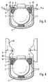
- the joint essentially exists from a housing 1, one in a recess 6 of the Housing 1 accommodated bearing shell 2, a pivot pin 7 with ball head 3 and a closure element 4.
- Usual sealing devices, especially bellows, are for the not relevant to the present invention and therefore not shown.
- the bearing shell 2 has the bottom of the recess 6 of the housing facing wall area one to this Wall area complementary conical taper 2a. Subsequently the bearing shell 2 on the outside of this area 2a Wall area a middle, cylindrical section 2d as well another conically tapering upper section 2c.
- closure element 4 is formed.
- the closure element 4 lies with a conical surface 4c on the top conical section 2c of the bearing shell 2.
- the closure element 4 is in the pin axis direction, i.e. in the Exemplary embodiments shown in the direction of that in FIG. 1 shown arrows F, slidably used in the housing 1.
- the housing recess 6 has an upper, with an enlarged diameter formed area 6a.
- On the inner wall 1a of this area 6a is the closure element 4 slidably guided with its outer wall 4a.
- the housing 1 is also formed with a shoulder 1b through which the displaceability of the closure element 4 is limited. Between the shoulder area 1b and one opposite this area Wall 4b of the closure element 4 is a game intended. The displaceability of the closure element 4 relative to the case is therefore determined by the size of this game.
- the ball joint Preload force evenly in the direction of the pin axis to realize force F applied to the closure element 4.
- the direction of the force F is shown in the figures by the arrows already mentioned. It is important to ensure that the locking element or the locking ring 4 in the area the desired preload with the housing, in illustrated embodiment thus the shoulder area 1b, comes into play. By choosing the height of the shoulder area 1b and the resulting game between this shoulder area 1b and the lower surface 4b of the closure element an adjustable preload range can be defined.
- the biasing force F acts on the bearing shell 2 and thus the ball head 3.
- the is evenly on the Closure element 4 applied force F to the bearing shell 2 and transfer the ball head 3, whereby the desired biasing force is adjustable in the ball joint.
- bearing shell 2 and housing 1 are matched to one another in this case, that the bearing shell 2 between the ball head and the housing 1st or the closure element 4 with a desired friction torque determining bias is maintained, which is preferred is chosen such that the only indicated Hinge pin 7 is pivotable without breakaway torque.
- the tolerance requirements for the individual components are here because of the force-related realization of the preload less than with conventional ball joints.
- the procedure is basically applicable to all ball joints, in which a closure element in the pin axis direction in to be fixed to the housing.
- FIGS. 2 and 3 correspond essentially that already described, in FIG. 1 illustrated embodiment.
- the same components are included here the same reference numerals.
- the embodiment of Figure 2 differs from that of Figure 1 in that the closure element 4 on the Hinge pin 7 arranged opposite side of the joint is. Furthermore, the closure element 4 is lid-shaped.
- closure element 4 an annular extension 4e, which itself in an area between the housing 1 and the bearing shell 2 extends.
- the closure element 4 is on the the hinge pin 7 opposite side of the hinge lid-shaped educated.
- the bearing shell 2 is on the outside with two lower, each other adjoining conical areas 2a, 2b with different Conicity angles formed which are complementary molded sections of the housing 1 abut.
- the opposite sections of Bearing shell and housing slightly different inclination or Conicity angle on, as for area 2a in the figure 4 is shown explicitly.
- By providing this angular play between housing 1 and bearing shell 2 is the introduction of the bearing shell 2 simplified into the housing during assembly.
- Preload larger component tolerances are accepted.
- the complementary conical bearing surfaces 4c, 2c of Closure element 4 and bearing shell 2 are slightly different Conicity angles formed, which also means here Larger component tolerances are possible.
- the bearing shell 2 is with a protruding area 11 formed into a complementary shaped recess 12 of the housing 1 engages. Furthermore, the Bearing shell to simplify the assembly of the ball head in the upper area evenly around the circumference in some places formed with slots 20.
- the bearing shell 2 inside in the area of the equatorial diameter 30 of the spherical head an annular recess 10, and in her Bottom area a further recess 21. With preload the bearing shell 2 is thereby ensured that the Kugekkopf in these recess areas not on the bearing shell rests, which can reduce wear.
- FIGS Various methods are shown schematically in FIGS for fixing or jamming the closure element 4 on the housing 1 shown.
- the same components are the same Provide reference numerals.
- the jamming serves to fix a position of the closure element 4, which the desired preload in the ball joint corresponds. This is how the pretension path is, as already explained not depending on the geometric dimensions of the Components, but realized by the selected preload.
- the fixation is carried out by means of bolts 40, which are pressed or pushed against the wall of the housing 1 with a sufficient force F Fix at several points along the circumference thereof. This causes a slight plastic deformation of the housing 1, which leads to a fixation of the position shell 2 on the housing 1.
- the formation of the closure element with triangular grooves 42 enables a positive connection between the housing and the closure element.
- the grooves 42 also ensure that the closure element does not change in its diameter, since the groove tips can yield to high forces.
- FIG. 6 shows a fixation by means of a flanging tool 44, which comes from above the housing wall laterally to the closure element 4 presses and thus permanently fixed.
- the illustrated Flaring tool 44 is designed such that the fixation an axial closing of the ball joint by means of flanging the upper sections 46 of the housing wall can follow. Also here is due to the geometric design of the closure element 4 a positive connection.
- FIG. 7 shows a top view of the ball joint according to FIG. 7.
- clamping jaws 50 are provided as an example.
- the housing is plastically deformed by the action of forces F Fix via the clamping jaws 50 and, due to the grooves on the closure element, is connected to it in a form-fitting manner.
- Flanging is an advantage. It is important to ensure that the location of the closure element 4 by the flanging process is changed.
Abstract
Description
Die vorliegende Erfindung betrifft ein Kugelgelenk, inbesondere
für Teile der Lenkung oder Radaufhängung von Kraftfahrzeugen,
mit den Merkmalen des Oberbegriffs des Patentanspruches 1, sowie
ein Verfahren zu seiner Vorspannung mit den Merkmalen des
Oberbegriffs des Patentanspruchs 16.The present invention relates to a ball joint, in particular
for parts of steering or wheel suspension of motor vehicles,
with the features of the preamble of
Moderne Kugelgelenke für den Einsatz in der Kraftfahrzeugtechnik müssen sich durch ein definiertes Reibmoment bei gleichzeitig hoher Gelenksteifigkeit auszeichnen. Diese Anforderungen werden erfüllt durch Vorsehen einer bestimmten Vorspannkraft des Kugelkopfes in Zapfenachsrichtung innerhalb eines montierten Gelenks. Diese Vorspannkraft wird in der Regel durch einen konstruktiv bedingten Vorspannweg aufgebracht, indem durch Bördeln gegen einen Anschlag das Gelenk verschlossen wird. Ein derartiges Bördelverfahren ist beispielsweise aus der DE 42 11 897 A1 bekannt. Aufgrund von Toleranzen der Abmaße der Einzelteile unterliegt dieser Vorspannweg, und somit die hierdurch verursachte Vorspannkraft, jedoch Streuungen, wodurch die Qualität der Gelenke stark beeinträchtigt ist.Modern ball joints for use in automotive engineering have to go through a defined friction torque at the same time high joint stiffness. These requirements are fulfilled by providing a certain preload of the ball head in the direction of the journal axis within an assembled Joint. This preload is usually determined by a constructive prestressing path applied by flanging the joint is closed against a stop. A Such flanging process is for example from DE 42 11 897 A1 known. Due to tolerances of the dimensions of the individual parts is subject to this pretensioning path, and thus to the resulting one preload caused, however, scattering, which increases the quality the joints are severely impaired.
Aufgabe der Erfindung ist daher die Schaffung eines Kugelgelenks, bei welchem eine Vorspannung des Kugelkopfes bezüglich seiner Lagerung in einfacher Weise mit einer geforderten Genauigkeit einstellbar ist.The object of the invention is therefore to create a ball joint, in which a preload of the ball head with respect its storage in a simple manner with a required accuracy is adjustable.
Diese Aufgabe wird gelöst durch ein Kugelgelenk mit den Merkmalen
des Patentanspruches 1, sowie durch ein Verfahren mit den
Merkmalen des Patentanspruches 16. This problem is solved by a ball joint with the features
of
Erfindungsgemäß ist es nun möglich, die Vorspannung weitgehend unabhängig von den Abmaßen und Toleranzen der Einzelteile einzustellen und während der Montage dauerhaft zu fixieren. Hierdurch können die Einzeltoleranzen erheblich aufgeweitet werden, womit eine wesentlich kostengünstigere Fertigung der Einzelteile ermöglicht wird. Da die Wirkung der Toleranzen auf das Kugelgelenk stark reduziert wird, kann die Qualität der gefertigten Kugelgelenke in einfacher Weise verbessert werden. Die Vorspannung des Kugelgelenks kann hierbei weitgehend unabhängig von den Abmaßen der Einzelteile unmittelbar über die auf das Verschlußelement des Kugelgelenks aufgebrachte Vorspannkraft eingestellt werden.According to the invention, it is now possible to largely pre-tension independent of the dimensions and tolerances of the individual parts and to fix it permanently during assembly. Hereby the individual tolerances can be widened considerably, which means a much more cost-effective production of the individual parts is made possible. Because the effect of tolerances on the ball joint is greatly reduced, the quality of the manufactured Ball joints can be improved in a simple manner. The preload the ball joint can be largely independent of the dimensions of the individual parts directly over the on the Closing element of the ball joint applied preload can be set.
Vorteilhafte Ausführungsformen der Erfindung sind Gegenstand der Unteransprüche.Advantageous embodiments of the invention are the subject of subclaims.
Nach einer bevorzugten Ausgestaltung sind das Verschlußelement und die Lagerschale und/oder die Lagerschale und das Gehäuse mit einander gegenüberliegenden, komplementären konusartigen Abschnitten ausgebildet. Durch diese konusartige bzw. winklige Ausbildung komplementärer Abschnitte der Kugelschale und des Verschlußelementes bzw. der Kugelschale und des Gehäuses wird eine in Achszapfrichtung bzw. axialer Richtung wirkende Vorspannkraft auf das Verschlußelement in die hierzu senkrechte radiale Richtung umgeleitet, so daß zusätzlich zur axialen Vorspannung auch die radiale Lage des Kugelkopfes festgelegt wird. Hierdurch ist es möglich, zusätzlich zu axialen auch radiale Toleranzen der Bauteile auszugleichen, so daß diese radiale Toleranzen aufgeweitet werden können, womit eine kostengünstigere Fertigung möglich ist. Durch die Kraftumlenkung ist also eine Herstellung von Gelenken mit verbesserter Qualität möglich, da die Einflüsse radialer Toleranzen durch das axiale Verschließen beeinflußbar sind.According to a preferred embodiment, the closure element and the bearing shell and / or the bearing shell and the housing with opposite, complementary cone-like Sections trained. Through this conical or angled Formation of complementary sections of the spherical shell and Closure element or the spherical shell and the housing a pretensioning force acting in the direction of the journal or the axial direction on the closure element in the perpendicular to this radial direction redirected so that in addition to the axial preload the radial position of the ball head is also determined. This makes it possible to use radial as well as axial ones Compensate tolerances of the components, so that these radial tolerances can be expanded, making a less expensive Manufacturing is possible. Due to the redirection of force is one Production of joints with improved quality possible because the influences of radial tolerances due to the axial locking can be influenced.
Zweckmäßigerweise sind die komplementären, konusartigen Abschnitte von Verschlußelement und Gehäuse und/oder Lagerschale und Gehäuse mit leicht unterschiedlichem Konizitätswinkeln ausgebildet. Hierdurch ist einerseits gewährleistet, daß der Anlagebereich zwischen Verschlußelement und Lagerschale möglichst nahe am Gelenkzapfen liegt, und andererseits daß eine optimale Verteilung der Vorspannkraft auf die gesamte Lagerschale möglich ist.The complementary, conical sections are expedient of closure element and housing and / or bearing shell and housing formed with slightly different taper angles. This ensures on the one hand that the investment area between the closure element and the bearing shell if possible is close to the pivot pin, and on the other hand that an optimal The preload can be distributed over the entire bearing shell is.
Bevorzugt ist, daß im Bereich des äquatorialen Durchmessers des Kugelkopfes das Gehäuse und die Lagerschale mit einander gegenüberliegenden, komplementären zylindrischen Abschnitten ausgebildet sindIt is preferred that in the region of the equatorial diameter of the Ball head the housing and the bearing shell with opposite, complementary cylindrical sections formed are
Zweckmäßigerweise ist hierbei zwischen diesen zylindrischen Abschnitten ein radiales Spiel ausgebildet. Dieses Spiel kann zur radialen Festlegung der Lagerschale bei Einwirkung einer axialen Kraft ausgenutzt werden. Ferner erleichtert es während der Montage die axiale Einführung der Lagerschale in das Gehäuse.It is expedient here between these cylindrical sections formed a radial game. This game can be used radial determination of the bearing shell when exposed to an axial Power can be used. It also facilitates during the Assemble the axial insertion of the bearing shell into the housing.
Gemäß einer bevorzgten Ausgestaltung sind das Verschlußelement und die Lagerschale und/oder die Lagerschale und das Gehäuse mit einander gegenüberliegenden, komplementären, im wesentlichen kugelschalenförmigen Abschnitten ausgebildet.According to a preferred embodiment, the closure element and the bearing shell and / or the bearing shell and the housing with opposite, complementary, essentially spherical shell-shaped sections.
Besonders bevorzugt ist hierbei, das die kugelschalenförmigen Abschnitte mit unterschiedlichen Krümmungsradien ausgebildet sind. Hierdurch sind die Toleranzanforderungen an Gehäuse und Lagerschale relativ niedrig, da eine Lagerschale mit einem etwas kleineren Krümmungsradius durch axiale bzw. radiale Vorspannung optimal an einen größeren Krümmungsradius des Gehäuses angepaßt werden kann.It is particularly preferred here that the spherical shell Sections formed with different radii of curvature are. As a result, the tolerance requirements for the housing and Bearing shell relatively low, as a bearing shell with something smaller radius of curvature due to axial or radial preload optimal to a larger radius of curvature of the housing can be adjusted.
Zweckmäßigerweise ist die Lagerschale im Bereich ihres äquatorialen Durchmessers innenseitig mit einer ringförmigen Aussparung ausgebildet.Hierdurch sind die Toleranzanforderungen an Kugelkopf und Lagerschale gegenüber herkömmlichen Systemen verringert. Ferner kann der Verschleiß des Kugelgelenks in diesem Bereich günstig beeinflußt werden. The bearing shell is expediently in the region of its equatorial one Inside diameter with an annular recess This means that the tolerance requirements are met Ball head and bearing shell reduced compared to conventional systems. Furthermore, the wear of the ball joint in this Range can be influenced favorably.
Bevorzugt ist ferner, daß die Lagerschale in ihrem Bodenbereich innenseitig mit einer Aussparung ausgebildet ist. Bei axialer Beaufschlagung der Lagerschale über das konisch ausgebildete Verschlußelement ist es unter Ausnutzung der ringförmigen Ausnehmung und dieser Ausnehmung im Bodenbereich möglich, im wesentlichen eine Dreipunktauflage des Kugelkopfes in der Lagerschale zu erzielen. Hierdurch kann der Verschleiß des Kugelgelenks verringert werden.It is further preferred that the bearing shell in its bottom area is formed on the inside with a recess. With axial Actuation of the bearing shell via the conical design Closure element, it is taking advantage of the annular recess and this recess in the bottom area possible, essentially a three-point support of the ball head in the bearing shell to achieve. This can cause wear on the ball joint be reduced.
Zweckmäßigerweise ist die Lagerschale in einem dem Gelenkzapfen zugekehrten Bereich mit einer Anzahl von Schlitzen ausgebildet, wodurch die Montage des Gelenks erleichtert ist.The bearing shell is expediently in one of the pivot pins facing area formed with a number of slots, making the assembly of the joint easier.
Es wird bevorzugt, daß die Lagerschale mit einem dem Gehäuse zugewandten vorstehenden Bereich ausgebildet ist, der in einen komplementär geformten Bereich des Gehäuses eingreift. Hiermit kann die Lage der Lagerschale innerhalb des Gehäuses in einfacher und zuverlässiger Weise fixiert werden.It is preferred that the bearing shell with a housing facing protruding area is formed, which in a engages complementarily shaped area of the housing. Herewith can the location of the bearing shell within the housing in easier and be fixed reliably.
Gemäß einer bevorzugten Ausgestaltung der Erfindung ist zwischen Verschlußelement und Gehäuse in Vorspannrichtung ein Spiel vorgesehen, wobei das Verschlußelement zur Festlegung der Gelenkvorspannung unter Ausnutzung des Spiels am Gehäuse verschieblich führbar und an einer beliebigen, der einzustellenden Vorspannung entsprechenden Position fixierbar ist. Hierdurch ist in einfacher Weise ein Bereich vorgebbar, innerhalb dessen eine Einstellung der Vorspannkraft möglich ist.According to a preferred embodiment of the invention, between Locking element and housing in the biasing direction Match provided, the closure element for fixing the Articulated preload can be moved on the housing using the play feasible and on any of the to be set Preload corresponding position can be fixed. Hereby an area can be specified in a simple manner, within which adjustment of the preload is possible.
Zweckmäßigerweise ist das Verschlußelement mittels Schweißens, insbesondere Laserschweißens am Gehäuse fixierbar. Die Fixierung mittels Laserschweißen ist gegenüber herkömmlichen Fixierverfahren in sehr einfacher und preiswerter Weise durchzuführen. Die Fixierung mittels Laserschweißens reduziert ferner den benötigten Bauraum und ermöglicht somit eine raumsparende Konstruktion. The closure element is expediently by means of welding, especially laser welding fixable on the housing. The fixation using laser welding is compared to conventional fixing methods to carry out in a very simple and inexpensive manner. The fixation by means of laser welding also reduces the required space and thus enables space-saving construction.
Gemäß einer weiteren vorteilhaften Ausgestaltung ist das Verschlußelement mittels Verformung des Gehäuses, insbesondere mittels Zusammendrückens der Gehäusewände senkrecht zur axialen Vorspannrichtung, am Gehäuse fixierbar. Hier bieten sich verschiedene Verfahren zur Verformung des Gehäuses an. Beispielsweise ist es möglich, die Gehäusewände mittels Bolzen, die mit einer für die Verformung ausreichenden Kraft an mehreren Stellen des Umfangs auf die Gehäusewand gestoßen werden, zu erzielen. Hierdurch erreicht man eine geringe plastische Verformung des Gehäuses bei gleichzeitiger Verbindung des Gehäuses mit dem Verschlußelement. Es ist ebenfalls möglich, die Fixierung mittels eines Bördelwerkzeuges durchzuführen, welches beispielsweise durch Bewegung in Vorspannrichtung die Gehäusewand seitlich an das Verschlußelement anpreßt und so dauerhaft fixiert. Es ist ferner möglich, die Fixierung mittels Spannbacken durchzuführen, die mit ausreichender Kraft das Gehäuse an das Verschlußelement pressen. Das Gehäuse wird hierbei in nur geringem Maße plastisch verformt.According to a further advantageous embodiment, the closure element by deformation of the housing, in particular by squeezing the housing walls perpendicular to the axial Preload direction, fixable on the housing. There are various options here Process for deforming the housing. For example it is possible to bolt the housing walls using bolts that a sufficient force for the deformation in several places of the circumference are encountered on the housing wall. This results in a low plastic deformation the housing while connecting the housing to the Closure element. It is also possible to use the fixation a flanging tool to perform, for example by moving in the direction of the preload the side of the housing presses against the closure element and thus permanently fixed. It is also possible to carry out the fixation by means of clamping jaws, the housing with sufficient force to the closure element press. The housing is only minimal Dimensions plastically deformed.
Zweckmäßigerweise ist das Verschlußelement an seiner äußeren Umfangsfläche und/oder der hiermit zusammenwirkende Innenwandbereich des Gehäuses mit sägezahnartigen oder dreieckförmigen Nuten bzw. Vorsprüngen ausgebildet. Hierdurch ist beim Zusammendrücken der Gehäusewand eine formschlüssige Verbindung von Gehäuse und Verschlußdeckel erzielbar. Durch die Nuten bzw. Vorsprünge wird gewährleistet, daß sich das Verschlußelement nicht im Durchmesser verändert, da die Nutspitzen hohen Kräften nachgeben können.The closure element is expediently on its outer Circumferential surface and / or the inner wall area interacting with it of the housing with sawtooth-like or triangular Grooves or projections formed. This is when squeezing the housing wall a positive connection of Housing and cover can be achieved. Through the grooves or Protrusions ensure that the closure element not changed in diameter, because the groove tips high forces can give in.
In der Zeichnung sind bevorzugte Ausführungsbeispiele der Erfindung im einzelnen darstellt.In the drawing are preferred embodiments of the invention represents in detail.
Es zeigt
Zunächst unter Bezugnahme auf Figur 1 wird das erfindungsgemäße
Kugelgelenk im einzelnen beschrieben. Das Gelenk besteht im wesentlichen
aus einem Gehäuse 1, einer in einer Ausnehmung 6 des
Gehäuses 1 aufgenommenen Lagerschale 2, einem Gelenkzapfen 7
mit Kugelkopf 3 und einem Verschlußelement 4. Übliche Dichtungsvorrichtungen,
insbesondere Dichtungsbalge, sind für die
vorliegende Erfindung nicht von Bedeutung und daher nicht dargestellt.
Die Lagerschale 2 weist an ihrem dem Boden der Ausnehmung
6 des Gehäuses zugekehrten Wandbereich eine zu diesem
Wandbereich komplementäre konische Verjüngung 2a auf. Anschließend
an diesen Bereich 2a weist die Lagerschale 2 außen als
Wandbereich einen mittleren, zylindrischen Abschnitt 2d sowie
einen sich hieran anschließenden weiteren konisch sich verjüngenden
oberen Abschnitt 2c auf.First with reference to Figure 1, the invention
Ball joint described in detail. The joint essentially exists
from a
Komplementär zu diesem oberen Abschnitt 2c der Lagerschale 2
ist ein Verschlußelement 4 ausgebildet. Das Verschlußelement 4
liegt mit einer konisch ausgebildeten Fläche 4c auf dem oberen
konischen Abschnitt 2c der Lagerschale 2 auf. Complementary to this
Das Verschlußelement 4 ist in Zapfenachsrichtung, d.h. in den
dargestellten Ausführungsbeispielen in Richtung der in Figur 1
dargestellten Pfeile F, verschieblich in das Gehäuse 1 einsetzbar.
Die Gehäuseausnehmung 6 weist hierbei einen oberen, mit
einem vergrößerten Durchmesser ausgebildeten Bereich 6a auf. An
der Innenwand 1a dieses Bereiches 6a ist das Verschlußelement 4
mit seiner äußeren Wandung 4a verschieblich geführt. Das Gehäuse
1 ist ferner mit einer Schulter 1b ausgebildet, durch welche
die Verschiebbarkeit des Verschlußelements 4 begrenzt ist. Zwischen
dem Schulterbereich 1b und einer diesem Bereich gegenüberliegenden
Wandung 4b des Verschlußelements 4 ist ein Spiel
vorgesehen. Die Verschiebbarkeit des Verschlußelements 4 relativ
zum Gehäuse ist daher durch die Größe dieses Spiels bestimmt.The
Erfindungsgemäß ist es nun möglich, die im Kugelgelenk einzustellende
Vorspannkraft über die in Zapfenachsrichtung gleichmäßig
auf das Verschlußelement 4 aufgebrachte Kraft F zu realisieren.
Die Richtung der Kraft F ist in den Figuren durch die
bereits erwähnten Pfeile dargestellt. Dabei ist darauf zu achten,
daß das Verschlußelement bzw. der Verschlußring 4 im Bereich
der angestrebten Vorspannkraft nicht mit dem Gehäuse, im
dargestellten Ausführungsbeispiel also dem Schulterbereich 1b,
zum Anschlag kommt. Durch Wahl der Höhe des Schulterbereichs 1b
und des sich somit ergebenden Spiels zwischen diesem Schulterbereich
1b und der unteren Fläche 4b des Verschlußelements ist
ein einstellbarer Vorspannkraftbereich definierbar. Über das
Verschlußelement 4 wirkt die Vorspannkraft F auf die Lagerschale
2 und somit den Kugelkopf 3.According to the invention, it is now possible to set the ball joint
Preload force evenly in the direction of the pin axis
to realize force F applied to the
Ist durch die Einwirkung der Vorspannkraft F die einer gewünschten
Vorspannung entsprechende Positionierung des Verschlußelements
erreicht, wird diese Position unter Beibehaltung
der Vorspannkraft F mittels Schweißens, insbesondere mittels
Laserschweißens, dauerhaft fixiert. Die Verschweißung des Verschlußelements
4 erfolgt beispielsweise mit einer schematisch
dargestellten Laserschweißvorrichtung 5. Is by the action of the biasing force F a desired one
Preload corresponding positioning of the closure element
reached, this position is maintained
the biasing force F by means of welding, in particular by means of
Laser welding, permanently fixed. The welding of the
Durch das beschriebene Verfahren wird die gleichmäßig auf das
Verschlußelement 4 aufgebrachte Kraft F auf die Lagerschale 2
und den Kugelkopf 3 übertragen, wodurch die gewünschte Vorspannkraft
im Kugelgelenk einstellbar ist. Miteinander korrespondierende
Durchmesserabmessungen von Kugelkopf 3, Lagerschale
2 und Gehäuse 1 sind hierbei derart aufeinander abgestimmt,
daß die Lagerschale 2 zwischen dem Kugelkopf und dem Gehäuse 1
bzw. dem Verschlußelement 4 mit einer ein gewünschtes Reibmoment
bestimmenden Vorspannung gehalten ist, die vorzugsweise
derart gewählt ist, daß der lediglich andeutungsweise dargestellte
Gelenkzapfen 7 ohne Losbrechmoment verschwenkbar ist.
Die Toleranzanforderungen an die einzelnen Bauteile sind hierbei
wegen der kraftbezogenen Realisierung der Vorspannung wesentlich
geringer als bei herkömmlichen Kugelgelenken.By the described method, the is evenly on the
Das Verfahren ist grundsätzlich auf alle Kugelgelenke anwendbar, bei denen ein Verschlußelement in Zapfenachsrichtung in dem Gehäuse fixiert werden soll.The procedure is basically applicable to all ball joints, in which a closure element in the pin axis direction in to be fixed to the housing.
Die in den Figuren 2 und 3 dargestellten Ausführungsformen entsprechen im wesentlichen der bereits beschriebenen, in Figur 1 dargestellten Ausführungsform. Gleiche Bauteile sind hier mit gleichen Bezugszeichen bezeichnet.The embodiments shown in FIGS. 2 and 3 correspond essentially that already described, in FIG. 1 illustrated embodiment. The same components are included here the same reference numerals.
Die Ausführungsform der Figur 2 unterscheidet sich von derjenigen
der Figur 1 dadurch, daß das Verschlußelement 4 auf der dem
Gelenkzapfen 7 entgegengesetzten Seite des Gelenks angeordnet
ist. Ferner ist das Verschlußelement 4 deckelförmig ausgebildet.The embodiment of Figure 2 differs from that
of Figure 1 in that the
Bei der in Figur 3 dargestellten Ausführungsform weist das Verschlußelement
4 eine ringförmige Verlängerung 4e auf, welche
sich in einem Bereich zwischen dem Gehäuse 1 und der Lagerschale
2 erstreckt. Auch hier ist das Verschlußelement 4 auf der
dem Gelenkzapfen 7 gegenüberliegenden Seite des Gelenks deckelförmig
ausgebildet. In the embodiment shown in Figure 3, the
Nicht nur an die axialen, sondern auch an die radialen Toleranzen sind bei den erfindungsgemäßen Kugelgelenken geringere Anforderungen gestellt. Die sei anhand der Ausführungsform gemäß Figur 4 im einzelnen erläutert. Auch hier sind gleiche Teile mit gleichen Bezugszeichen versehen.Not just the axial, but also the radial tolerances are lower requirements for the ball joints according to the invention posed. This is based on the embodiment according to Figure 4 explained in detail. Here are the same parts provided with the same reference numerals.
Mittels der konischen Anlageflächen von Verschlußelement 4 und
Lagerschale 2 bzw. Lagerschale 2 und Gehäuse 1 erfährt eine
axial wirkende Vorspannkraft eine Umlenkung in die radiale
Richtung, so daß auch die radiale Position des Kugelkopfes 3
bzw. der Lagerschale 2 innerhalb des Gehäuses 1 festgelegt
wird. Durch eine entsprechende Gestaltung der Bauteile können
die üblicherweise strengen Anforderungen an die radiale Toleranzkette
vermindert werden.By means of the conical contact surfaces of the
Die Lagerschale 2 ist außenseitig mit zwei unteren, sich aneinander
anschließenden konischen Bereichen 2a, 2b mit unterschiedlichen
Konizitätswinkeln ausgebildet, welche an komplementär
geformten Abschnitten des Gehäuses 1 anliegen. Hierbei
weisen die einander jeweils gegenüberliegenden Abschnitte von
Lagerschale und Gehäuse leicht unterschiedliche Neigungs- bzw.
Konizitätswinkel auf, wie dies für den Bereich 2a in der Figur
4 explizit dargestellt ist. Durch Vorsehen dieses Winkelspiels
zwischen Gehäuse 1 und Lagerschale 2 ist die Einführung der Lagerschale
2 in das Gehäuse während der Montage vereinfacht.
Ferner können auch hier aufgrund der axial und radial wirkenden
Vorspannung größere Bauteiltoleranzen in Kauf genommen werden.
Auch die komplementären konischen Auflageflächen 4c, 2c von
Verschlußelement 4 und Lagerschale 2 sind mit leicht unterschiedlichen
Konizitätswinkeln ausgebildet, wodurch auch hier
größere Bauteiltoleranzen möglich sind.The bearing
Es sei angemerkt, daß die konischen Bereiche 2a,2b der Lagerschale
und die komplementären Bereiche des Gehäuses durch kugelschalenförmige
Bereiche ersetzt werden können. Hierbei ist
darauf zu achten, daß der Kugelradius der Lagerschale 2 etwas
kleiner ist als der komplementäre Bereich des Gehäuses, so daß
auch bei dieser Ausführung die oben beschriebenen Vorteile bezüglich
Montage und Bauteiltoleranzen erzielbar sind.It should be noted that the
Zur Fixierung am Gehäuse 1 ist die Lagerschale 2 mit einem
vorstehenden Bereich 11 ausgebildet, der in eine komplementär
geformte Ausnehmung 12 des Gehäuses 1 eingreift. Ferner ist die
Lagerschale zur Vereinfachung der Montage des Kugelkopfes im
oberen Bereich gleichmäßig über den Umfang an einigen Stellen
mit Schlitzen 20 ausgebildet.For fixing to the
Gemäß dem dargestellten Ausführungsbeispiel weist die Lagerschale
2 innenseitig im Bereich des äquatorialen Durchmessers
30 des Kugelkopfes eine ringförmige Ausnehmung 10, sowie in ihrem
Bodenbereich eine weitere Ausnehmung 21 auf. Bei Vorspannung
der Lagerschale 2 ist hierdurch gewährleistet, daß der Kugekkopf
in diesen Ausnehmungsbereichen nicht auf der Lagerschale
aufliegt, wodurch der Verschleiß vermindert werden kann.According to the illustrated embodiment, the bearing
In den Figuren 5 bis 8 sind schematisch verschiedene Verfahren
zur Festlegung bzw. Verklemmung des Verschlußelemets 4 am Gehäuse
1 dargestellt. Auch hier sind gleiche Bauteile mit gleiche
Bezugszeichen versehen.Various methods are shown schematically in FIGS
for fixing or jamming the
Das Verklemmen dient zur Fixierung einer Position des Verschlußelements
4, welche der gewünschten Vorspannung im Kugelgelenk
entspricht. So wird, wie bereits erläutert, der Vorspannweg
nicht in Abhängigkeit von den geometrischen Maßen der
Bauteile, sondern von der gewählten Vorspannkraft realisiert.The jamming serves to fix a position of the
In Figur 5 erfolgt die Fixierung mittels Bolzen 40, die mit einer
ausreichenden Kraft FFix an mehreren Stellen des Umfangs der
Wand des Gehäuses 1 gegen diese gedrückt bzw gestoßen werden.
Hierdurch wird eine geringe plastische Verformung des Gehäuses
1 bewirkt, welche zu einer Fixierung der Lageschale 2 am Gehäuse
1 führt. Die Ausbildung des Verschlußelements mit dreiecksförmigen
Nuten 42 ermöglicht hierbei eine formschlüssige Verbindung
von Gehäuse und Verschlußelement. Durch die Nuten 42
wird ferner gewährleistet, daß sich das Verschlußelement in
seinem Durchmesser nicht verändert, da die Nutspitzen hohen
Kräften nachgeben können.In FIG. 5, the fixation is carried out by means of
Figur 6 zeigt eine Fixierung mittels eines Bördelwerkzeugs 44,
welches von oben kommend die Gehäusewand seitlich an das Verschlußelement
4 anpreßt und so dauerhaft fixiert. Das dargestellte
Bördelwekzeug 44 ist derart ausgebildet, daß der Fixierung
ein axiales Verschließen des Kugelgelenks mittels Umbördelung
der oberen Abschnitte 46 der Gehäusewand folgen kann. Auch
hier erfolgt durch die geometriche Ausgestaltung des Verschlußelements
4 eine formschlüssige Verbindung.FIG. 6 shows a fixation by means of a
Gemäß Figur 7 erfolgt die Fixierung mittels Spannbacken 50, die
das Gehäuse 1 an das Verschlußelement pressen. In Figur 8 ist
eine Draufsicht auf das Kugelgelenk gemäß Figur 7 dargestellt.
Beispielhaft sind vier Spannbacken 50 vorgesehen. Das Gehäuse
wird hierbei durch Einwirkung von Kräften FFix über die Spannbacken
50 plastisch verformt und aufgrund der Nuten am Verschlußelement
formschlüssig mit diesem verbunden.According to FIG. 7, the fixation is carried out by means of clamping
Sind hohe Auszugskräfte gefordert, so ist ein nachträgliches
Bördeln von Vorteil. Dabei ist darauf zu achten, daß die Lage
des Verschlußelements 4 durch den Bördelvorgang nicht weiter
verändert wird.If high pull-out forces are required, a subsequent one is required
Flanging is an advantage. It is important to ensure that the location
of the
Claims (19)
dadurch gekennzeichnet, daß
das Verschlußelement (4) unter Beaufschlagung der Lagerschale (2) am Gehäuse (1) in einer axialen Vorspannrichtung verschieblich führbar und in einer beliebigen, einer einzustellenden Vorspannung entsprechenden Position fixierbar ist.Ball joint, in particular for parts of the steering or wheel suspension of motor vehicles, with a bearing shell (2) receiving a ball head (3) of a joint pin (7) on the inside, which is supported in a housing (1), and one on the outside of the bearing shell (2) overlying closure element (4), by means of which the bearing shell (2) can be preloaded with respect to the housing (1) and the ball head (3),
characterized in that
the closure element (4) can be guided in an axial preload direction and can be fixed in any position corresponding to a preload that is to be set, by acting on the bearing shell (2) on the housing (1).
gekennzeichnet durch folgende Schritte:
characterized by the following steps:
Applications Claiming Priority (2)
| Application Number | Priority Date | Filing Date | Title |
|---|---|---|---|
| DE19756984 | 1997-12-20 | ||
| DE1997156984 DE19756984A1 (en) | 1997-12-20 | 1997-12-20 | Ball joint and procedure for its preload |
Publications (1)
| Publication Number | Publication Date |
|---|---|
| EP0924441A1 true EP0924441A1 (en) | 1999-06-23 |
Family
ID=7852811
Family Applications (1)
| Application Number | Title | Priority Date | Filing Date |
|---|---|---|---|
| EP98122313A Withdrawn EP0924441A1 (en) | 1997-12-20 | 1998-11-24 | Ball joint and procedure to bias it |
Country Status (2)
| Country | Link |
|---|---|
| EP (1) | EP0924441A1 (en) |
| DE (1) | DE19756984A1 (en) |
Cited By (7)
| Publication number | Priority date | Publication date | Assignee | Title |
|---|---|---|---|---|
| WO2004083660A1 (en) * | 2003-03-18 | 2004-09-30 | Kongsberg Automotive Asa | Ball joint device |
| WO2005124169A1 (en) * | 2004-06-18 | 2005-12-29 | Zf Friedrichshafen Ag | Central joint for an a-arm of motor vehicles |
| WO2006018004A1 (en) * | 2004-08-19 | 2006-02-23 | Zf Friedrichshafen Ag | Ball and socket joint and method for producing the same |
| WO2008083808A2 (en) | 2007-01-12 | 2008-07-17 | Trw Automotive Gmbh | Ball joint |
| EP1967323A3 (en) * | 2007-03-08 | 2009-07-15 | BESSEY Tool GmbH & Co. KG | Device for applying pressure on a workpiece |
| US11396906B2 (en) * | 2018-07-18 | 2022-07-26 | Federal-Mogul Motorparts, LLC | Ball socket assembly with a preload bearing |
| DE102022003676A1 (en) | 2022-10-05 | 2024-04-11 | Mercedes-Benz Group AG | Ball joint for a chassis of a vehicle, in particular a motor vehicle |
Families Citing this family (9)
| Publication number | Priority date | Publication date | Assignee | Title |
|---|---|---|---|---|
| DE102004040412B4 (en) | 2004-08-19 | 2006-12-14 | Zf Friedrichshafen Ag | Ball sleeve joint and method for its production |
| DE102005060719A1 (en) * | 2005-12-19 | 2007-06-21 | Siemens Ag | Method for caulking a first part |
| DE102006008250A1 (en) * | 2006-02-22 | 2007-08-23 | Trw Automotive Gmbh | Ball and socket joint e.g. for axial joint, has housing, bearing shell which is arranged in housing, and ball-headed spindle having ball head which is arranged in bearing shell |
| DE102006024198A1 (en) * | 2006-05-23 | 2007-12-27 | Trw Automotive Gmbh | Method for producing a ball joint and ball joint |
| DE102006043930B4 (en) * | 2006-09-14 | 2009-08-13 | Zf Friedrichshafen Ag | ball joint |
| DE102011114204A1 (en) | 2011-09-23 | 2012-11-29 | Daimler Ag | Ball-and-socket joint for axle guide of vehicle, has external thread portion formed at external periphery of locking ring and connected with internal thread portion, which is formed at inner wall of universal joint housing |
| DE102013105091A1 (en) | 2013-05-17 | 2014-11-20 | Benteler Automobiltechnik Gmbh | Ball joint and motor vehicle handlebar |
| WO2020085138A1 (en) * | 2018-10-24 | 2020-04-30 | 日本発條株式会社 | Ball-sheet-securing structure for ball joint |
| JP7228449B2 (en) * | 2018-10-24 | 2023-02-24 | 日本発條株式会社 | Ball joint ball seat fixing structure |
Citations (6)
| Publication number | Priority date | Publication date | Assignee | Title |
|---|---|---|---|---|
| DE1922123A1 (en) * | 1968-05-06 | 1969-11-13 | Gen Motors Corp | Process for the production of ball joints for the automotive industry |
| US3950006A (en) * | 1972-09-11 | 1976-04-13 | Trw Inc. | Rack and pinion steering assembly |
| US4163617A (en) * | 1977-02-14 | 1979-08-07 | Musashisemitsukoguo Kabushikikaisha | Ball joint |
| FR2446694A1 (en) * | 1979-01-17 | 1980-08-14 | Dba | JOINT JOINT ASSEMBLY METHOD |
| FR2498494A1 (en) * | 1981-01-23 | 1982-07-30 | Dba | METHOD AND APPARATUS FOR MANUFACTURING A BALL AND ROTULE THUS OBTAINED |
| EP0342351A1 (en) * | 1988-05-14 | 1989-11-23 | TRW Ehrenreich GmbH & Co. KG | Ball joint |
Family Cites Families (1)
| Publication number | Priority date | Publication date | Assignee | Title |
|---|---|---|---|---|
| DE19513826C1 (en) * | 1995-04-12 | 1996-07-04 | Trw Fahrwerksyst Gmbh & Co | Ball-and-socket joint for utility vehicles |
-
1997
- 1997-12-20 DE DE1997156984 patent/DE19756984A1/en not_active Withdrawn
-
1998
- 1998-11-24 EP EP98122313A patent/EP0924441A1/en not_active Withdrawn
Patent Citations (6)
| Publication number | Priority date | Publication date | Assignee | Title |
|---|---|---|---|---|
| DE1922123A1 (en) * | 1968-05-06 | 1969-11-13 | Gen Motors Corp | Process for the production of ball joints for the automotive industry |
| US3950006A (en) * | 1972-09-11 | 1976-04-13 | Trw Inc. | Rack and pinion steering assembly |
| US4163617A (en) * | 1977-02-14 | 1979-08-07 | Musashisemitsukoguo Kabushikikaisha | Ball joint |
| FR2446694A1 (en) * | 1979-01-17 | 1980-08-14 | Dba | JOINT JOINT ASSEMBLY METHOD |
| FR2498494A1 (en) * | 1981-01-23 | 1982-07-30 | Dba | METHOD AND APPARATUS FOR MANUFACTURING A BALL AND ROTULE THUS OBTAINED |
| EP0342351A1 (en) * | 1988-05-14 | 1989-11-23 | TRW Ehrenreich GmbH & Co. KG | Ball joint |
Cited By (12)
| Publication number | Priority date | Publication date | Assignee | Title |
|---|---|---|---|---|
| WO2004083660A1 (en) * | 2003-03-18 | 2004-09-30 | Kongsberg Automotive Asa | Ball joint device |
| WO2005124169A1 (en) * | 2004-06-18 | 2005-12-29 | Zf Friedrichshafen Ag | Central joint for an a-arm of motor vehicles |
| WO2006018004A1 (en) * | 2004-08-19 | 2006-02-23 | Zf Friedrichshafen Ag | Ball and socket joint and method for producing the same |
| DE102004040403A1 (en) * | 2004-08-19 | 2006-03-09 | Zf Friedrichshafen Ag | Ball joint and method for its production |
| WO2008083808A2 (en) | 2007-01-12 | 2008-07-17 | Trw Automotive Gmbh | Ball joint |
| WO2008083808A3 (en) * | 2007-01-12 | 2008-08-28 | Trw Automotive Gmbh | Ball joint |
| US8734044B2 (en) | 2007-01-12 | 2014-05-27 | Trw Automotive Gmbh | Ball joint with an elastic bearing shell |
| KR101420204B1 (en) * | 2007-01-12 | 2014-07-17 | 티알더블유 오토모티브 게엠베하 | Ball joint |
| EP1967323A3 (en) * | 2007-03-08 | 2009-07-15 | BESSEY Tool GmbH & Co. KG | Device for applying pressure on a workpiece |
| US8267389B2 (en) | 2007-03-08 | 2012-09-18 | Bessey Tool Gmbh & Co. Kg | Device for applying pressure to a workpiece |
| US11396906B2 (en) * | 2018-07-18 | 2022-07-26 | Federal-Mogul Motorparts, LLC | Ball socket assembly with a preload bearing |
| DE102022003676A1 (en) | 2022-10-05 | 2024-04-11 | Mercedes-Benz Group AG | Ball joint for a chassis of a vehicle, in particular a motor vehicle |
Also Published As
| Publication number | Publication date |
|---|---|
| DE19756984A1 (en) | 1999-07-08 |
Similar Documents
| Publication | Publication Date | Title |
|---|---|---|
| EP0924441A1 (en) | Ball joint and procedure to bias it | |
| DE19755020B4 (en) | Axial | |
| EP0253117B1 (en) | Ball joint | |
| EP3445980B1 (en) | Axial ball joint and length-adjustable two-point link with such an axial ball joint | |
| EP0836018B1 (en) | Ball joint and method of mounting | |
| WO2006018005A1 (en) | Ball and socket joint and method for producing the same | |
| EP0778421A1 (en) | Ball joint | |
| EP2803512B1 (en) | Ball joint and motor vehicle steering device | |
| DE10201022A1 (en) | ball joint | |
| EP3601013B1 (en) | Adjustable steering column for vehicle | |
| DE102008042281A1 (en) | Shaft bearing for use in worm gear of electric power steering system of motor vehicle, has holder connected with shaft, accommodating inner ring and comprising recesses enabling pivot movement towards section of holder | |
| EP0348642A1 (en) | Ball joint | |
| EP1676038B1 (en) | Ball joint bearing, especially for mutually centering two shaft ends | |
| EP1456544A1 (en) | Ball-and-socket joint | |
| DE69931693T2 (en) | Holder for a constant velocity joint | |
| WO2003053766A1 (en) | Steering knuckle pin bearing | |
| WO2006018004A1 (en) | Ball and socket joint and method for producing the same | |
| EP1052418A2 (en) | Ball-joint | |
| EP0751310B1 (en) | Ball joint | |
| EP0600227B1 (en) | Motor vehicle door ball and socket hinge | |
| WO1990000130A1 (en) | Device for producing a preferably controllable axial counterforce on a rotating shaft which can be displaced axially by an axial force | |
| EP1671044B1 (en) | Constant velocity joint having crossed raceways, universal joint shaft and method for producing it | |
| EP1681478B1 (en) | Ball joint | |
| DE10159037B4 (en) | Adjustment device for motor vehicle seats | |
| DE10163147A1 (en) | Ball and socket joint for vehicles has housing with protrusions and indentations on inside sleeve face to positively lock oversized bearing shell inserted therein through plastic deformation |
Legal Events
| Date | Code | Title | Description |
|---|---|---|---|
| PUAI | Public reference made under article 153(3) epc to a published international application that has entered the european phase |
Free format text: ORIGINAL CODE: 0009012 |
|
| AK | Designated contracting states |
Kind code of ref document: A1 Designated state(s): DE ES FR GB IT |
|
| AX | Request for extension of the european patent |
Free format text: AL;LT;LV;MK;RO;SI |
|
| 17P | Request for examination filed |
Effective date: 19990506 |
|
| AKX | Designation fees paid |
Free format text: DE ES FR GB IT |
|
| STAA | Information on the status of an ep patent application or granted ep patent |
Free format text: STATUS: THE APPLICATION HAS BEEN WITHDRAWN |
|
| 18W | Application withdrawn |
Withdrawal date: 20001209 |