EP1743732B1 - Buchsen mit Doppelflansch und Montageverfahren - Google Patents
Buchsen mit Doppelflansch und Montageverfahren Download PDFInfo
- Publication number
- EP1743732B1 EP1743732B1 EP06022883.0A EP06022883A EP1743732B1 EP 1743732 B1 EP1743732 B1 EP 1743732B1 EP 06022883 A EP06022883 A EP 06022883A EP 1743732 B1 EP1743732 B1 EP 1743732B1
- Authority
- EP
- European Patent Office
- Prior art keywords
- tubular
- bushing
- opening
- flange
- work member
- Prior art date
- Legal status (The legal status is an assumption and is not a legal conclusion. Google has not performed a legal analysis and makes no representation as to the accuracy of the status listed.)
- Expired - Lifetime
Links
- 238000000034 method Methods 0.000 title description 6
- 238000009434 installation Methods 0.000 title description 5
- 230000002708 enhancing effect Effects 0.000 claims abstract description 11
- 239000000463 material Substances 0.000 description 5
- 239000000314 lubricant Substances 0.000 description 4
- 229910000906 Bronze Inorganic materials 0.000 description 3
- 229910045601 alloy Inorganic materials 0.000 description 3
- 239000000956 alloy Substances 0.000 description 3
- 239000000565 sealant Substances 0.000 description 3
- 229910001369 Brass Inorganic materials 0.000 description 2
- 239000010951 brass Substances 0.000 description 2
- 239000010974 bronze Substances 0.000 description 2
- 238000010276 construction Methods 0.000 description 2
- 229910052751 metal Inorganic materials 0.000 description 2
- 229910000975 Carbon steel Inorganic materials 0.000 description 1
- RYGMFSIKBFXOCR-UHFFFAOYSA-N Copper Chemical compound [Cu] RYGMFSIKBFXOCR-UHFFFAOYSA-N 0.000 description 1
- 229910052782 aluminium Inorganic materials 0.000 description 1
- XAGFODPZIPBFFR-UHFFFAOYSA-N aluminium Chemical compound [Al] XAGFODPZIPBFFR-UHFFFAOYSA-N 0.000 description 1
- 229910052790 beryllium Inorganic materials 0.000 description 1
- ATBAMAFKBVZNFJ-UHFFFAOYSA-N beryllium atom Chemical compound [Be] ATBAMAFKBVZNFJ-UHFFFAOYSA-N 0.000 description 1
- 239000002131 composite material Substances 0.000 description 1
- 229910052802 copper Inorganic materials 0.000 description 1
- 239000010949 copper Substances 0.000 description 1
- KUNSUQLRTQLHQQ-UHFFFAOYSA-N copper tin Chemical compound [Cu].[Sn] KUNSUQLRTQLHQQ-UHFFFAOYSA-N 0.000 description 1
- 230000001419 dependent effect Effects 0.000 description 1
- 229910001026 inconel Inorganic materials 0.000 description 1
- 239000002184 metal Substances 0.000 description 1
- 239000007769 metal material Substances 0.000 description 1
- 229910001220 stainless steel Inorganic materials 0.000 description 1
Images


Classifications
-
- B—PERFORMING OPERATIONS; TRANSPORTING
- B23—MACHINE TOOLS; METAL-WORKING NOT OTHERWISE PROVIDED FOR
- B23P—METAL-WORKING NOT OTHERWISE PROVIDED FOR; COMBINED OPERATIONS; UNIVERSAL MACHINE TOOLS
- B23P9/00—Treating or finishing surfaces mechanically, with or without calibrating, primarily to resist wear or impact, e.g. smoothing or roughening turbine blades or bearings; Features of such surfaces not otherwise provided for, their treatment being unspecified
- B23P9/02—Treating or finishing by applying pressure, e.g. knurling
- B23P9/025—Treating or finishing by applying pressure, e.g. knurling to inner walls of holes by using axially moving tools
-
- F—MECHANICAL ENGINEERING; LIGHTING; HEATING; WEAPONS; BLASTING
- F16—ENGINEERING ELEMENTS AND UNITS; GENERAL MEASURES FOR PRODUCING AND MAINTAINING EFFECTIVE FUNCTIONING OF MACHINES OR INSTALLATIONS; THERMAL INSULATION IN GENERAL
- F16B—DEVICES FOR FASTENING OR SECURING CONSTRUCTIONAL ELEMENTS OR MACHINE PARTS TOGETHER, e.g. NAILS, BOLTS, CIRCLIPS, CLAMPS, CLIPS OR WEDGES; JOINTS OR JOINTING
- F16B4/00—Shrinkage connections, e.g. assembled with the parts at different temperature; Force fits; Non-releasable friction-grip fastenings
- F16B4/004—Press fits, force fits, interference fits, i.e. fits without heat or chemical treatment
-
- Y—GENERAL TAGGING OF NEW TECHNOLOGICAL DEVELOPMENTS; GENERAL TAGGING OF CROSS-SECTIONAL TECHNOLOGIES SPANNING OVER SEVERAL SECTIONS OF THE IPC; TECHNICAL SUBJECTS COVERED BY FORMER USPC CROSS-REFERENCE ART COLLECTIONS [XRACs] AND DIGESTS
- Y10—TECHNICAL SUBJECTS COVERED BY FORMER USPC
- Y10T—TECHNICAL SUBJECTS COVERED BY FORMER US CLASSIFICATION
- Y10T29/00—Metal working
- Y10T29/49—Method of mechanical manufacture
- Y10T29/49826—Assembling or joining
- Y10T29/49863—Assembling or joining with prestressing of part
-
- Y—GENERAL TAGGING OF NEW TECHNOLOGICAL DEVELOPMENTS; GENERAL TAGGING OF CROSS-SECTIONAL TECHNOLOGIES SPANNING OVER SEVERAL SECTIONS OF THE IPC; TECHNICAL SUBJECTS COVERED BY FORMER USPC CROSS-REFERENCE ART COLLECTIONS [XRACs] AND DIGESTS
- Y10—TECHNICAL SUBJECTS COVERED BY FORMER USPC
- Y10T—TECHNICAL SUBJECTS COVERED BY FORMER US CLASSIFICATION
- Y10T29/00—Metal working
- Y10T29/49—Method of mechanical manufacture
- Y10T29/49826—Assembling or joining
- Y10T29/49908—Joining by deforming
- Y10T29/49909—Securing cup or tube between axially extending concentric annuli
- Y10T29/49911—Securing cup or tube between axially extending concentric annuli by expanding inner annulus
-
- Y—GENERAL TAGGING OF NEW TECHNOLOGICAL DEVELOPMENTS; GENERAL TAGGING OF CROSS-SECTIONAL TECHNOLOGIES SPANNING OVER SEVERAL SECTIONS OF THE IPC; TECHNICAL SUBJECTS COVERED BY FORMER USPC CROSS-REFERENCE ART COLLECTIONS [XRACs] AND DIGESTS
- Y10—TECHNICAL SUBJECTS COVERED BY FORMER USPC
- Y10T—TECHNICAL SUBJECTS COVERED BY FORMER US CLASSIFICATION
- Y10T29/00—Metal working
- Y10T29/49—Method of mechanical manufacture
- Y10T29/49826—Assembling or joining
- Y10T29/49908—Joining by deforming
- Y10T29/49915—Overedge assembling of seated part
- Y10T29/4992—Overedge assembling of seated part by flaring inserted cup or tube end
-
- Y—GENERAL TAGGING OF NEW TECHNOLOGICAL DEVELOPMENTS; GENERAL TAGGING OF CROSS-SECTIONAL TECHNOLOGIES SPANNING OVER SEVERAL SECTIONS OF THE IPC; TECHNICAL SUBJECTS COVERED BY FORMER USPC CROSS-REFERENCE ART COLLECTIONS [XRACs] AND DIGESTS
- Y10—TECHNICAL SUBJECTS COVERED BY FORMER USPC
- Y10T—TECHNICAL SUBJECTS COVERED BY FORMER US CLASSIFICATION
- Y10T29/00—Metal working
- Y10T29/49—Method of mechanical manufacture
- Y10T29/49826—Assembling or joining
- Y10T29/49908—Joining by deforming
- Y10T29/49938—Radially expanding part in cavity, aperture, or hollow body
- Y10T29/4994—Radially expanding internal tube
-
- Y—GENERAL TAGGING OF NEW TECHNOLOGICAL DEVELOPMENTS; GENERAL TAGGING OF CROSS-SECTIONAL TECHNOLOGIES SPANNING OVER SEVERAL SECTIONS OF THE IPC; TECHNICAL SUBJECTS COVERED BY FORMER USPC CROSS-REFERENCE ART COLLECTIONS [XRACs] AND DIGESTS
- Y10—TECHNICAL SUBJECTS COVERED BY FORMER USPC
- Y10T—TECHNICAL SUBJECTS COVERED BY FORMER US CLASSIFICATION
- Y10T29/00—Metal working
- Y10T29/49—Method of mechanical manufacture
- Y10T29/49826—Assembling or joining
- Y10T29/49945—Assembling or joining by driven force fit
-
- Y—GENERAL TAGGING OF NEW TECHNOLOGICAL DEVELOPMENTS; GENERAL TAGGING OF CROSS-SECTIONAL TECHNOLOGIES SPANNING OVER SEVERAL SECTIONS OF THE IPC; TECHNICAL SUBJECTS COVERED BY FORMER USPC CROSS-REFERENCE ART COLLECTIONS [XRACs] AND DIGESTS
- Y10—TECHNICAL SUBJECTS COVERED BY FORMER USPC
- Y10T—TECHNICAL SUBJECTS COVERED BY FORMER US CLASSIFICATION
- Y10T403/00—Joints and connections
- Y10T403/49—Member deformed in situ
- Y10T403/4924—Inner member is expanded by longitudinally inserted element
-
- Y—GENERAL TAGGING OF NEW TECHNOLOGICAL DEVELOPMENTS; GENERAL TAGGING OF CROSS-SECTIONAL TECHNOLOGIES SPANNING OVER SEVERAL SECTIONS OF THE IPC; TECHNICAL SUBJECTS COVERED BY FORMER USPC CROSS-REFERENCE ART COLLECTIONS [XRACs] AND DIGESTS
- Y10—TECHNICAL SUBJECTS COVERED BY FORMER USPC
- Y10T—TECHNICAL SUBJECTS COVERED BY FORMER US CLASSIFICATION
- Y10T403/00—Joints and connections
- Y10T403/49—Member deformed in situ
- Y10T403/4991—Both members deformed
Definitions
- the present invention relates to the provision and installation of tubular bushings in openings in work members. More particularly, it relates to the provision of bushings having flanges at both ends.
- U.S. Patent No. 5,103,548, granted April 14, 1992, to Leonard F. Reid and Roger T. Dolstad discloses the use of a mandrel and a split sleeve together for installing a tubular bushing in an opening in a work member and at the same time introducing fatigue life enhancing compressive residual stresses in the work member.
- U.S. Patent No. 3,835,688, granted September 17, 1974, to John O. King, Jr. and U.S. Patent No. 3,949,535, granted April 13, 1976, also to John O. King, Jr. each discloses a method of both installing a seamless tubular member in openings in two members to be joined and expanding the material immediately surrounding the openings for the purposes of fatigue life enhancement.
- the seamless tubular members disclosed by these patents have a flange at one end that contacts the side of one of the members from which the tubular member is inserted.
- Patent No. 3,949,535 discloses providing a flare on the end of the sleeve opposite the flange to assist in retaining the sleeve in the opening in the workpiece. This flare is formed by the movement of the mandrel through the sleeve and it requires a particular end construction of the sleeve.
- the lug might see a load transmitted to the pin through the lug perpendicular to the axis of the bore, due to the weight of the aircraft. However, it could also see an axial load due to the fore and aft loading of the lug.
- a second flange on a bushing could also be used to provide a surface on which a nut and washer may seat when a threaded pin is used to retain the pin in the joint.
- the principal object of the present invention is to provide tubular bushings having flanges at both of their ends.
- EP 89/007 and EP 945919 disclose the features of the preamble of claim 1.
- a workpiece that includes first and second sides and a cylindrical opening extending through it between the two sides.
- a bushing is provided that includes a tubular center portion that is placed within the cylindrical opening.
- a first radial flange is connected to the tubular center portion of the bushing on the first side of the work member. This flange extends radially outwardly from the tubular center portion of the bushing, in contact with the first side of the work member.
- a second radial flange is connected to the tubular center portion of the bushing on the second side of the work member. This second radial bushing extends radially outwardly from the tubular center portion of the bushing, in contact with the second side of the work member.
- the tubular center portion of the bushing is radially expanded in the cylindrical opening to such an extend that it makes a tight interference fit within the opening connects the bushing to the work member, and induces fatigue life enhancing compressive residual stresses in the work member immediately around the opening in the work member.
- the tubular center portion of the bushing is a single continuous tubular member that is connected at one end to the first flange and which includes a second end portion that extends axially outwardly beyond the second side of the work member.
- the second flange is a radial member having a center opening in which the projecting end portion of the tubular member is received.
- the tubular member is radially expanded in the center opening of the second flange to such an extent that it makes a tight interference fit with the opening in the second flange and connects the second flange to the tubular member.
- the bushing is composed of a first bushing part that includes the first flange and a first tubular member that is connected to the first flange, and a second bushing part that includes the second flange and a second tubular member that is connected to the second flange.
- the two tubular members together form at least a part of the central portion of the bushing.
- the first tubular member may extend substantially completely through the opening and the second tubular member may be positioned in the first tubular member and extends substantially completely through it.
- the two tubular members are concentric. The radial expansion connects the first tubular member to the sidewall of the opening and connects the second tubular member to the first tubular member.
- the first tubular member extends axially from a first flange into and partially through the cylindrical opening in the work member.
- the second tubular member extends from the second flange into and partially through the opening in the work member, coaxial with the first tubular member.
- the outside diameters of the tubular members may be close in size to the inside diameter of the opening, so that when radially expanded, the two tubular members make a tight interference fit with the opening in the work member.
- the first and second tubular members may be surrounded by a third tubular member, in which case the radial expansion connects the first tubular member to the sidewall of the opening in the work member and connects the second and third tubular members of the bushing parts to the first tubular member. That is, the third tubular member makes a tight interference fit with the cylindrical opening in the work member and the second and third tubular members make tight interference fits with the first tubular member.
- a work member that has a first side and an opposite second side.
- a cylindrical through opening is provided in the work member, extending from the first side to the second side.
- a first bushing part is provided that has a tubular section and a radial flange section at one end of the tubular section.
- the tubular section has an outside diameter substantially corresponding to the diameter of the through opening in the work member.
- the tubular section of the first bushing part is inserted into and through the opening in the work member, from the first side of the work member.
- the first bushing part is moved axially to place its flanged section against the first side of the work member.
- the tubular section of the first bushing part is of such a length that when the flange section is against the first side of the work member, the tubular section has an end portion opposite the flanged section that projects axially outwardly of the opening, beyond the second side of the work member.
- a second bushing part includes a center opening that is sized to receive the projecting end portion of the tubular section of the first bushing part.
- the second busing part extends radially outwardly from this center opening.
- the second bushing part is positioned on the projecting end portion of the tubular section of the first bushing part and is moved substantially against the second side of the work member.
- the tubular section of the first bushing member is radially and circumferentially expanded an amount sufficient to provide a tight interference fit between it and the through opening in the work member and between its projecting end portion and the opening in the second bushing part.
- This connects the first bushing part to the work member and connects the second bushing part to the projecting end portion of the tubular section of the first bushing part, such that the second bushing part functions as a second flange at the end of the first bushing part that is opposite the flange section of the first bushing part.
- tubular section of the bushing part is radially expanded an amount sufficient to also introduce fatigue life enhancing compressive residual stresses in the work member immediately around the opening in the work member.
- the cold expansion of the tubular section may be accomplished by moving a tapered mandrel axially through the first bushing part, and providing the mandrel with a large diameter end portion that is sized such that when it moves through the tubular section of the first bushing part it will radially expand the tubular section of the first bushing part to the extent needed.
- a first bushing part that has a tubular section and a radial flange section at one end of its tubular section.
- the tubular section of the first bushing part is provided with an outside diameter substantially corresponding to the diameter of the opening in the work member.
- the second bushing part is provided that has a tubular section and a radial flange section at one end of its tubular section.
- the tubular section of the second bushing part is provided with an outside diameter substantially corresponding to the inside diameter of the tubular section of the first bushing part. The tubular section of the first bushing part is moved into and through the opening in the work member, from the first side of the work member.
- the tubular sections of the first and second bushing parts are radially and circumferentially expanded together, an amount sufficient to provide a tight interference fit of the tubular section of the second bushing part in the tubular section of the first bushing part, and a tight interference fit of the tubular section of the first bushing part in the opening in the work member. They also are radially and circumferentially expanded an amount sufficient to also introduce fatigue life enhancing compressive residual stresses in the work member immediately around the opening in the work member.
- a first bushing part that has a tubular section and a radial flange at one end of the tubular section.
- the tubular section has an outside diameter substantially corresponding to the diameter of the opening in the work member and a length that is only a portion of the length of the opening in the work member.
- a second bushing part is provided that has a tubular section and a radial flange at one end of the tubular section. This tubular section also has an outside diameter substantially corresponding to the diameter of the opening in the work member and a length that is less than the length of the opening in the work member.
- the tubular section of the first bushing part is inserted into the opening in the work member, from the first side of the work member, and is moved axially to place the flange section of the first bushing part against the first side of the work member.
- the tubular section of the second bushing part is inserted into the opening in the work member, from the second side of the work member, and is moved axially until the flange section of the second bushing part is against the second side of the work member. Then, the two tubular sections are radially and circumferentially expanded an amount sufficient to provide a tight interference fit between them and the opening in the work member, for connecting the first and second bushing parts to the work member.
- the cold expansion may also be sufficient to introduce fatigue life enhancing compressive residual stresses in the work member immediately around a through opening in the work member.
- a tubular first bushing part that has an outside diameter substantially corresponding to the diameter of the opening in the work member and a length substantially corresponding to the length of the opening in the work member.
- a second bushing part is provided that has a tubular section and a radial flange section at one end of the tubular section.
- the tubular section of the second bushing part has an outside diameter substantially corresponding to the inside diameter of the first bushing part and a length that is a portion of the length of the first bushing part.
- a third bushing part is provided. It has a tubular section and a radial flange section at one end of the tubular section.
- the tubular section of the third bushing part also has an outside diameter substantially conforming to the inside diameter of the first bushing part and a length that is a portion of the length of the first bushing part.
- the first bushing part is inserted into the opening in the work member.
- the tubular section of the second bushing part is inserted into the first bushing part, from the first side of the work member.
- the second bushing part is moved axially until its flange section is against the first side of the work member.
- the tubular section of the third bushing part is inserted into the first bushing part, from the second side of the work member.
- the third bushing part is moved axially until its flange section is against the second side of the work member.
- first bushing part and the tubular sections of the second and third bushing parts are radially expanded together an amount sufficient to provide a tight interference fit between the first bushing part and the opening in the work member and between the tubular sections of the second and third bushing parts and the first bushing part.
- the bushing parts are expanded circumferentially an amount sufficient to connect the second and third bushing parts to the first bushing part and connect the first bushing part to the work member. They also are radially expanded an amount sufficient to introduce fatigue life enhancing compressive residual stresses in the work member substantially surrounding the through opening in the work member.
- Fig. 1 shows prior art tooling for installing a prior art bushing 10.
- the tooling includes a puller 12 that includes a nose piece 14 having a forward end surface 16 and a mandrel receiving opening 18.
- the mandrel M includes a small diameter inner end portion 20 that extends into the puller 12 via the opening 18. It further includes a bushing receiving central portion 22 and an enlarged end portion 24.
- This installation of the mandrel M is shown by the aforementioned U.S. Patents Nos. 4,809,420 and 5,433,100 . Reference is made to Patent No. 5,433,100 for a more complete description and disclosure of the mandrel and puller assembly.
- Figs. 2 , 6-8 and 12 disclose a first embodiment of the double flanged bushings of the present invention.
- This bushing 25 is composed of a first bushing part 26 and a second bushing part 28.
- Bushing part 26 comprises a tubular section 30 and a radial flange section 32.
- Flange section 32 is connected to one end of the tubular section 30.
- Tubular section 26 extends axially and radial flange section 32 extends radially.
- Bushing part 28 is a radial member 34 that includes a center opening 36.
- the radial length of member 34 substantially equals the radial length of flange section 32 measured from the outside diameter of the tubular section 30.
- a through opening 38 is provided in a work member 40 to receive the bushing 25.
- An initial opening 38 is formed by use of a drill. The drilled opening is then reamed to provide a desired starting diameter. After reaming, the starting diameter is verified by use of a hole-diameter gauge. If the opening 38 is oversized, it must be reworked to provide it with a proper slightly larger diameter. An appropriate primer may be applied to the opening 38.
- Figs-. 6-8 show the bushing 28 in the process of being installed into the opening 38 in a work member 40, shown in the form of a structural wall 40.
- the tubular section 30 of bushing part 26 has an outside diameter substantially corresponding to the diameter of opening 38.
- Tubular section 30 has a length that is slightly longer than the length of the opening 38, so as to provide it with an end portion 42 that projects axially outwardly from the second wall 44 of the member 40 when the flange 32 is against the first wall 46 of the member 40.
- the opening 36 in member 34 has a diameter substantially corresponding to the outside diameter of end part tubular section 30.
- End portion 42 has a length substantially corresponding to the thickness of the member 34.
- the tubular section 30 of member 26 is inserted into the opening 38, from the first side of the member 40. It is moved axially through the opening 38 until the radial flange 32 contacts sidewall 48. When this happens, the end portion 42 of tubular section 30 projects axially outwardly of the opening 30, beyond the second surface 44. It may be desirable to apply a sealant to the inwardly side of the flange 32.
- the second bushing part 28 is installed on this end portion 42. Bushing part 28 is moved towards the end portion 42 until the end portion 42 is inside the opening 36. It might be desirable to apply a sealant to the inward surface of bushing part 28.
- the mandrel M is inserted through the tubular section 30, from the first side of the member 40. Its inner end portion 20 is connected to a piston inside of the puller 12, such as is disclosed in U.S. Patent No. 5,433,100 , with reference to Figs. 20 and 21 of that patent.
- mandrel section 22 is inside the tubular section 30 and the enlarged end portion 24 of the mandrel M is spaced from the first side 46 of member 40.
- the surface 16 on nose piece 14 is positioned against member 34 such that member 34 is clamped between surface 16 and surface 44.
- the puller 12 is operated to retract the mandrel M and pull it through the tubular section 30.
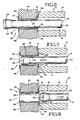
- Fig. 7 shows the mandrel M in the process of being retracted and shows its enlarged end portion 24 in the process of stretching and enlarging tubular section 30 both radially and circumferentially as it moves through tubular section 30.
- the drag of the mandrel head 24 on the tubular section 30 pulls the flange 32 of bushing part 26 tight against surface 26.
- a reaction to the pulling force moves the nose piece 14 forwardly to place its forward surface 16 into tight contact with the radial member 34.
- movement of the mandrel M pulls flange 32 into tight contact with surface 46 and pushes the member 34 into tight contact with surface 44.
- the tubular section 30 is expanded to make a tight interference fit with the sidewall of opening 38.
- the enlarged portion 22 of the mandrel M moves through the end portion 42 of tubular section 38, it radially and circumferentially expands the end portion 42, causing a tight interference fit between it and the sidewall of opening 36 in member 34.
- Fig. 8 shows the mandrel M fully retracted within the nose piece 14 of the puller 12.
- the end portion 25 of the mandrel M has been moved entirely through the tubular section 30.
- the puller 12 and mandrel M are freely movable away from the installed bushing 26, 28.
- Fig. 8 shows an axial space 48 starting to form between side surface 44 of member 40 and end surface 16 of nose piece 14. It further shows the bushing parts 26,28 installed within the opening 18.
- the installed bushing parts 26, 28, are also shown in Fig. 12 , with the puller 12 having been moved away from the work member 40.
- the inside surface of the tubular section 30 might be slightly tapered. In that case the opening in tubular section 30 may be reamed to a desired inside diameter and to remove lubricant residual.
- the lubricant residual may be present because it is common practice to use a lubricant between a mandrel M and a bushing through which the mandrel M is moved.
- FIGs. 3 , and 13 show another form of two part bushing 50.
- a first bushing part 52 has a tubular section 54 and a radial flange section 56 at one end of the tubular section 54.
- the tubular section 54 has an outside diameter substantially conforming to the opening 38 in the work member 40.
- Tubular section 54 has a length measured from the inside of flange section 56 to its opposite end that substantially corresponds to the length of the opening 38.
- Bushing part 58 has a tubular section 60 and a radial flange section 62 connected to one end of the tubular section 60.
- Tubular section 60 has an outside diameter substantially conforming to the inside diameter of tubular section 54. It has a length substantially conforming to the length of the opening in tubular section 54.
- the opening 38 is formed and prepared in the manner described above. Primer may be applied to the inside of the opening 38. Sealant may be applied to the inside surfaces of the flanges 56, 62 of the bushing 50.
- the bushing 50 is installed in the following manner.
- the tubular section 54 of bushing part 52 is inserted into the opening 38 in the work member 40, from the first side of the work member 40. It is then pushed axially inwardly until the inner surface of flange section 56 contacts the side surface 46 on the work member 40.
- the tubular section 60 of the bushing part 58 is installed into the opening in bushing section 54, from the second side of the work member. It is moved inwardly until the inner surface of flange section 62 contacts the sidewall 44 of work member 40.
- the mandrel M and puller 12 are used to radially and circumferentially expand the two tubular sections 54, 60.
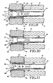
- the mandrel M is installed in the manner described above in connection with Figs. 6-8 and a lubricant is used between it and the bushing 50. It is then pulled axially into the puller 12 so as to move its enlarged end portion 24 axially through tubular section 60, as shown in Fig. 9 , which shows a variant of the two part bushing of figures 3 and 13 .
- the mandrel head 24 radially and circumferentially expands both tubular section 60 and tubular section 54.
- Figs. 4 , 10 and 14 disclose a third embodiment of the bushing.
- This bushing 66 has three parts.
- a tubular first bushing part 68 has an outside diameter and a length that correspond to the diameter and length of opening 38 in work member 40.
- the second bushing part 70 has a tubular section 72 and a radial flange section 74 at one end of the tubular section 72. It has an outside diameter substantially conforming to the inside diameter of bushing part 68. It has a length that is shorter than the opening 38 in work member 40.
- the third bushing part 76 has a tubular section 78 and a radial flange section 80 at one end of the tubular section 78.
- bushing parts 70, 76 are alike.
- the tubular sections 72, 78 are substantially the length of tubular section 68 and the opening 38 in the work member 40.
- Bushing 66 is installed in the following manner. Firstly, bushing part 68 is placed in the opening 38 in work member 40. Then, tubular section 72 of bushing part 70 is inserted into the bushing part 68 from the first side of the work member 40. Bushing part 76 is inserted into the bushing part 68 from the opposite side of the work member. The bushing parts 70, 76 are moved toward each other until radial flange 74 is substantially against side surface 46 and radial flange 80 is substantially against side surface 44. Then, the mandrel M and the puller 12 are used in a manner described above in connection with the first two embodiments.
- bushing part 68 is moved into a tight interference fit with the sidewall of opening 38.
- Tubular sections 72, 78 and bushing part 70, 78 are moved into a tight interference fit with bushing part 68.
- Flange section 74 is pulled into tight contact with side surface 46 and flange section 80 is pushed into tight contact with side surface 44.
- the expansion connects bushing part 68 to the side surface of opening 38 and connects tubular sections 72, 78 of bushing parts 70, 76 to bushing part 68.
- Tubular sections 72, 78 may have concentric overlapping portions where they meet. This is shown by Fig. 17 .
- End portion 72' is shown to concentrically surround end portion 78'.
- Figs. 5 , 8 and 15 show a fourth embodiment of the bushing.
- This bushing 86 is composed of two bushing parts 88, 90 which are preferably identical in construction.
- Bushing part 88 has a tubular section 92 and a radial flange section 94 that is connected to one end of the tubular section 92.
- Bushing part 90 has a tubular section 96 and a radial flange section 98'that is connected to one end of the tubular section 96.
- the outside diameters of the tubular sections 92, 98 substantially conform to the diameter of the opening 38 in the work member 40.
- the tubular sections 92, 96 are both shorter than the opening 38 but, preferably, their combined lengths substantially equal the length of the opening 38 ( Fig. 15 ).
- the tubular sections 92, 96 may have concentric end portions that form a lap joint where they meet. End part 92' concentrically surrounds end part 96'.
- the bushing 86 is installed in the following manner.
- the tubular sections 92, 96 are either installed separately or together into the opening 38 from opposite sides of the work member.
- the bushing parts 86, 90 are moved axially together until flange section 94 substantially contacts sidewall 46 and flange section 98 substantially contacts side surface 44.
- the mandrel 20 and the puller 12 are used in the manner described above for radially and circumferentially expanding the tubular sections 92, 98 in the opening 38.
- axial movement of the mandrel 20 through the tubular sections of the bushing acts to pull flange section 94 against sidewall 46 and push flange section 98 against sidewall 44.
- the installation of bushings 50, 66, 86 includes radially and circumferentially expanding the tubular sections of the bushing parts an amount sufficient to introduce fatigue life enhancing compressive residual stresses in the work member immediately around the opening 38 in the work member 40.
- the various bushing parts that have been described can be made from any suitable metal that has to date been used for making bushings and from new materials that might be developed for use in making bushings, or for use in making other structures but suitable for use in making bushings.
- Typical examples are bronze, bronze alloys, brass, brass alloys, aluminum, aluminum-nickel-bronze, copper beryllium, stainless steels and Inconel and other high temperature engine alloys, alloys, and carbon steels, etc.
- the work member 40 may be a structural wall or it may be some other structural member. It may be made from metal or composite materials.
Landscapes
- Engineering & Computer Science (AREA)
- Mechanical Engineering (AREA)
- Forging (AREA)
- Mutual Connection Of Rods And Tubes (AREA)
- Springs (AREA)
- Flanged Joints, Insulating Joints, And Other Joints (AREA)
- Shafts, Cranks, Connecting Bars, And Related Bearings (AREA)
- Heat Treatment Of Articles (AREA)
Claims (8)
- In Kombination:ein Werkstück (40), das eine erste und eine zweite Seite (44, 46) sowie eine zylindrische Öffnung (38) umfasst, die sich zwischen den beiden Seiten durch das Werkstück ausdehnt; undeine Buchse (26; 50; 66; 86), umfassend:einen röhrenförmigen Mittelbereich (30; 54; 60; 72, 68, 78; 92; 96) innerhalb der zylindrischen Öffnung;eine erste radiale Flansch (32; 56; 74; 94), die mit dem röhrenförmigen Mittelbereich der Buchse verbunden ist und die sich radial nach außen von dieser ausdehnt, wobei sie Kontakt mit der ersten Seite des Werkstücks hat;eine zweite radiale Flansch (34; 62; 80; 98), die mit dem röhrenförmigen Mittelbereich der Buchse verbunden ist und die sich radial nach außen von dieser ausdehnt, wobei sie Kontakt mit der zweiten Seite des Werkstücks hat; dadurch gekennzeichnet, dassder röhrenförmige Mittelbereich der Buchse in der zylindrischen Öffnung derart radial ausgedehnt ist, dass er eine enge Presspassung mit der Öffnung bildet, die Buchse mit dem Werkstück verbindet und Lebensdauer verlängernde Druckrestspannungen in das Werkstück im unmittelbaren Bereich um die Öffnung des Werkstücks induziert.
- Kombination gemäß Anspruch 1, wobei der röhrenförmige Mittelbereich der Buchse ein einzelnes, durchgängiges Rohrstück (30) darstellt, das an dem einen Ende mit der ersten Flansch (32) verbunden ist und sich von dieser Flansch durch die Öffnung in das Werkstück ausdehnt, und das einen zweiten Endbereich umfasst, der sich weiterhin axial nach außen ausdehnt über die zweite Seite des Werkstücks hinaus; wobei es sich bei der zweiten Flansch (34) um ein radiales Stück (28) handelt, das in der Mitte eine Öffnung aufweist, in die das Endstück des einzelnen, durchgängigen Rohrstücks aufgenommen wird; und wobei
das einzelne, durchgängige Rohrstück derart radial in der Öffnung in der Mitte der zweiten Flansch ausgedehnt ist, dass es eine enge Presspassung mit der Öffnung in der zweiten Flansch bildet und die zweite Flansch mit dem durchgängigen Rohrstück verbindet. - Kombination gemäß Anspruch 1, wobei die Buchse (50) aus einem ersten Teil (52; 70; 88), der die erste Flansch (56; 74; 94) und ein erstes Rohrstück (54; 72; 92) umfasst, das mit der ersten Flansch verbunden ist, sowie aus einem zweiten Teil (58; 76; 90), der die zweite Flansch (62; 80; 98) und ein zweites Rohrstück (60; 78; 96) umfasst, das mit der zweiten Flansch verbunden ist, besteht; und wobei das erste und das zweite Rohrstück sich beide innerhalb der zylindrischen Durchgangsöffnung des Werkstücks befinden und gemeinsam wenigstens einen Teil des Mittelstücks der Buchse bilden.
- Kombination gemäß Anspruch 3, wobei das erste Rohrstück (54) sich von der ersten Flansch (56) durch die zylindrische Durchgangsöffnung in das Werkstück hinein ausdehnt und ein zweites Ende aufweist, das an die zweite Flansch (62) angrenzt; und wobei das zweite Rohrstück (58) sich von der zweiten Flansch (62) durch das erste Rohrstück ausdehnt und ein zweites Ende aufweist, das an die erste Flansch (56) angrenzt.
- Kombination gemäß Anspruch 3, wobei das erste Rohrstück (70, 88) sich von der ersten Flansch in die zylindrische Durchgangsöffnung hinein und zum Teil durch sie hindurch in das Werkstück hinein ausdehnt, und das zweite Rohrstück (76, 90) sich von der zweiten Flansch in die zylindrische Durchgangsöffnung hinein und zum Teil durch sie hindurch in das Werkstück hinein ausdehnt.
- Kombination gemäß Anspruch 5, wobei das erste und das zweite Rohrstück koaxial sind und eine äußere Oberfläche haben, die die enge Presspassung mit der zylindrischen Durchgangsöffnung des Werkstücks bildet.
- Kombination gemäß Anspruch 5, wobei das erste und das zweite Rohrstück (70, 76) koaxial sind und von einem dritten Rohrstück (68) umgeben sind, und das erste, das zweite sowie das dritte Rohrstück gemeinsam den röhrenförmigen Mittelbereich der Buchse (66) bilden.
- Kombination gemäß Anspruch 7, wobei das dritte Rohrstück (68) eine enge Presspassung bildet mit der zylindrischen Durchgangsöffnung in das Werkstück, und das erste und das zweite Rohrstück (70, 76) eine enge Presspassung mit dem dritten Rohrstück bilden.
Applications Claiming Priority (2)
| Application Number | Priority Date | Filing Date | Title |
|---|---|---|---|
| US09/603,857 US7375277B1 (en) | 2000-06-26 | 2000-06-26 | Double flanged bushings and installation methods |
| EP01202458A EP1166951B1 (de) | 2000-06-26 | 2001-06-26 | Montageverfahren für Buschen mit Doppelflansch |
Related Parent Applications (1)
| Application Number | Title | Priority Date | Filing Date |
|---|---|---|---|
| EP01202458A Division EP1166951B1 (de) | 2000-06-26 | 2001-06-26 | Montageverfahren für Buschen mit Doppelflansch |
Publications (3)
| Publication Number | Publication Date |
|---|---|
| EP1743732A2 EP1743732A2 (de) | 2007-01-17 |
| EP1743732A3 EP1743732A3 (de) | 2007-03-28 |
| EP1743732B1 true EP1743732B1 (de) | 2015-08-12 |
Family
ID=24417206
Family Applications (2)
| Application Number | Title | Priority Date | Filing Date |
|---|---|---|---|
| EP01202458A Expired - Lifetime EP1166951B1 (de) | 2000-06-26 | 2001-06-26 | Montageverfahren für Buschen mit Doppelflansch |
| EP06022883.0A Expired - Lifetime EP1743732B1 (de) | 2000-06-26 | 2001-06-26 | Buchsen mit Doppelflansch und Montageverfahren |
Family Applications Before (1)
| Application Number | Title | Priority Date | Filing Date |
|---|---|---|---|
| EP01202458A Expired - Lifetime EP1166951B1 (de) | 2000-06-26 | 2001-06-26 | Montageverfahren für Buschen mit Doppelflansch |
Country Status (4)
| Country | Link |
|---|---|
| US (4) | US7375277B1 (de) |
| EP (2) | EP1166951B1 (de) |
| AT (1) | ATE346716T1 (de) |
| DE (1) | DE60124820T2 (de) |
Families Citing this family (58)
| Publication number | Priority date | Publication date | Assignee | Title |
|---|---|---|---|---|
| US7375277B1 (en) * | 2000-06-26 | 2008-05-20 | Fatigue Technology, Inc. | Double flanged bushings and installation methods |
| US7448652B2 (en) * | 2003-07-31 | 2008-11-11 | Fatigue Technology Inc. | Tubular metal fitting expandable in a wall opening and method of installation |
| US7204412B2 (en) * | 2003-10-14 | 2007-04-17 | Compucredit Intellectual Property Holdings Corp. Iii | Family stored value card program |
| US7047596B2 (en) * | 2003-12-09 | 2006-05-23 | Sikorsky Aircraft Corp. | Structural bushing application for highly loaded composites lugs |
| DE602005008426D1 (de) * | 2004-04-15 | 2008-09-04 | Fatigue Technology Inc | Verfahren und vorrichtung unter einsatz von exzenterbuchsen |
| US20070110541A1 (en) * | 2005-10-28 | 2007-05-17 | Fatigue Technology, Inc. | Radially displaceable bushing for retaining a member relative to a structural workpiece |
| EP1803526B1 (de) * | 2005-12-28 | 2017-03-15 | Fatigue Technology, Inc. | Dorneinheit und Verfahren zu ihrer Verwendung |
| US8568034B2 (en) | 2006-01-11 | 2013-10-29 | Fatigue Technology, Inc. | Bushing kits, bearings, and methods of installation |
| US7874059B2 (en) * | 2006-01-12 | 2011-01-25 | Siemens Energy, Inc. | Attachment for ceramic matrix composite component |
| US7823262B2 (en) * | 2006-03-14 | 2010-11-02 | Sps Technologies, Llc | Method of replacing a nut plate fastener assembly |
| US20070289351A1 (en) * | 2006-04-27 | 2007-12-20 | Fatigue Technology, Inc. | Wave relieving geometric features in structural members that are radially expandable into workpieces |
| EP2388104B1 (de) | 2006-04-27 | 2019-04-10 | Fatigue Technology, Inc. | Ausrichtungsvorrichtung und Verfahren zu deren Verwendung |
| US20080005887A1 (en) * | 2006-05-26 | 2008-01-10 | Fatigue Technology, Inc. | Elongated member/radially expandable member assembly and methods of assembling the same |
| EP2029390B1 (de) * | 2006-06-02 | 2012-10-24 | Johnson Controls Technology Company | Fahrzeugsitzrahmen und verfahren |
| EP2568183A3 (de) | 2006-06-29 | 2015-04-08 | Fatigue Technology, Inc. | Selbstausrichtende Werkzeuge und Dorn mit Haltebuchse |
| EP2489462A1 (de) | 2006-08-28 | 2012-08-22 | Fatigue Technology, Inc. | System zum Bearbeiten eines Werkstücks und Verfahren zum Ausdehnen eines ausdehnbaren Elements |
| US7682117B2 (en) * | 2006-09-27 | 2010-03-23 | Illinois Tool Works Inc. | Work piece isolating assembly |
| US7575404B2 (en) * | 2006-11-01 | 2009-08-18 | Sps Technologies, Llc | Nut plate fastener assembly for composite materials |
| WO2008144440A2 (en) * | 2007-05-15 | 2008-11-27 | Fatigue Technology, Inc. | Blind installed expandable collar and threaded inner member |
| US7967097B2 (en) * | 2007-06-06 | 2011-06-28 | Jeremy Ore | Motorcycle suspension method and apparatus |
| DE202007011491U1 (de) * | 2007-08-16 | 2007-10-18 | Acument Gmbh & Co. Ohg | Vorrichtung zur Befestigung von Kunststoffteilen an einer Kraftfahrzeugkarosserie |
| US8312606B2 (en) | 2007-10-16 | 2012-11-20 | Fatigue Technology, Inc. | Expandable fastener assembly with deformed collar |
| US7950711B2 (en) | 2008-01-28 | 2011-05-31 | A. Raymond Et Cie | Body mount |
| EP2259884B1 (de) | 2008-03-07 | 2018-11-28 | Fatigue Technology, Inc. | Dehnbares element mit welleninhibitor und anwendungsverfahren dafür |
| US8506222B2 (en) * | 2008-07-18 | 2013-08-13 | Fatigue Technology, Inc. | Nut plate assembly and methods of using the same |
| DE102008053346A1 (de) * | 2008-10-27 | 2010-04-29 | Profil Verbindungstechnik Gmbh & Co. Kg | Abstandselement für die Anbringung an einem Blechteil, Zusammenbauteil und Verfahren zu dessen Herstellung |
| US8251659B2 (en) * | 2008-11-26 | 2012-08-28 | General Electric Company | Insert for through-holes and method therefor |
| US8636455B2 (en) | 2009-04-10 | 2014-01-28 | Fatigue Technoloy, Inc. | Installable assembly having an expandable outer member and a fastener with a mandrel |
| US8647035B2 (en) | 2009-12-16 | 2014-02-11 | Fatigue Technology, Inc. | Modular nut plate assemblies and methods of using the same |
| CN101791756B (zh) * | 2010-03-02 | 2012-06-20 | 江苏大学 | 一种锥密封管接头高精度锥孔弹性滚轧装置 |
| WO2012167136A2 (en) | 2011-06-03 | 2012-12-06 | Fatigue Technology, Inc. | Expandable crack inhibitors and methods of using the same |
| US9114449B2 (en) | 2011-06-15 | 2015-08-25 | Fatigue Technology, Inc. | Modular nut plates with closed nut assemblies |
| US9108363B2 (en) * | 2011-10-06 | 2015-08-18 | The Boeing Company | Thin wall bushing for robust electrical bonding to fiber-reinforced structures |
| US8745819B2 (en) * | 2011-11-18 | 2014-06-10 | The Boeing Company | Load sustaining bushing |
| WO2013116111A1 (en) | 2012-01-30 | 2013-08-08 | Fatigue Technology, Inc. | Smart installation/processing systems, components, and methods of operating the same |
| FR2989618A1 (fr) * | 2012-04-24 | 2013-10-25 | Skf Aerospace France | Dispositif de renfort destine a ameliorer le comportement d'au moins une partie d'une piece composite |
| US8965624B2 (en) * | 2012-08-14 | 2015-02-24 | Ebay Inc. | Method and system of vehicle tracking portal |
| US9073620B2 (en) | 2013-06-07 | 2015-07-07 | Honda Patents & Technologies North America, Llc | Fastening device for window |
| US9364880B1 (en) * | 2013-06-14 | 2016-06-14 | The Boeing Company | Systems and methods to cold work metal/composite structures |
| US20150198230A1 (en) * | 2014-01-13 | 2015-07-16 | Electro-Motive Diesel Inc. | Cam follower assembly having swaged bushing |
| GB201408213D0 (en) * | 2014-05-09 | 2014-06-25 | Avdel Uk Ltd | Apparatus and methods for providing a threaded fixing in a crushable or brittle material |
| JP6020611B2 (ja) * | 2015-01-20 | 2016-11-02 | トヨタ自動車株式会社 | 車両データのリモート収集システム |
| US20170089644A1 (en) | 2015-09-30 | 2017-03-30 | Spx Flow, Inc. | Port Connection for a Heat Exchanger |
| CN105499907B (zh) * | 2016-01-21 | 2017-08-01 | 吉林大学 | 一种提高轴类零件内孔加工精度的装置 |
| CN105822843A (zh) * | 2016-05-31 | 2016-08-03 | 江苏金由新材料有限公司 | 一种ptfe管材与金属花板的密封结构及其密封方法 |
| EP3333527A1 (de) * | 2016-12-08 | 2018-06-13 | Alfa Laval Corporate AB | Auskleidungsvorrichtung und wärmetauscher |
| US10655671B2 (en) * | 2016-12-29 | 2020-05-19 | Goodrich Corporation | Nested bushing arrangement |
| GB2562748A (en) * | 2017-05-23 | 2018-11-28 | Airbus Operations Ltd | Bearing assembly |
| JP6939091B2 (ja) * | 2017-05-26 | 2021-09-22 | トヨタ紡織株式会社 | 乗物用シート |
| GB2568756A (en) * | 2017-11-28 | 2019-05-29 | Airbus Operations Ltd | Fastener |
| US11660804B2 (en) | 2017-12-12 | 2023-05-30 | Aquatechnik Group S.P.A. | Device for expanding and shaping the end of pipes and an extracting member for use with such a device |
| JP6873372B2 (ja) * | 2018-09-11 | 2021-05-19 | 日立Astemo株式会社 | 支持構造体 |
| CN110405699B (zh) * | 2019-06-13 | 2021-06-22 | 中建四局第六建设有限公司 | 一种用于回收锥形穿墙套管的便携式工具及使用方法 |
| JP7272194B2 (ja) * | 2019-09-11 | 2023-05-12 | 積水ハウス株式会社 | Cltパネル補強構造物 |
| CN111516275B (zh) * | 2020-04-27 | 2022-05-03 | 四川中自科技有限公司 | 一种无扩口导管连接件挤压成型设备 |
| CN112139368B (zh) * | 2020-09-09 | 2022-10-21 | 南通昭和机械有限公司 | 一种有效减缓板式热交换器腐蚀衬套翻边工艺 |
| US11873108B2 (en) * | 2021-09-17 | 2024-01-16 | Ami Industries, Inc. | Drogue to seat separation assembly having pyrotechnic fastener |
| US11807175B2 (en) * | 2021-10-08 | 2023-11-07 | Safran Cabin Germany Gmbh | Cable harness grommet and method for using same |
Family Cites Families (173)
| Publication number | Priority date | Publication date | Assignee | Title |
|---|---|---|---|---|
| GB593607A (en) | 1945-06-08 | 1947-10-21 | Arthur Buescher | Improvements in arbors |
| US295593A (en) | 1884-03-25 | Jambs f | ||
| US810430A (en) * | 1904-02-11 | 1906-01-23 | Frank Pfluger | Bung-hole bushing. |
| US1081496A (en) | 1908-03-23 | 1913-12-16 | Horatio G Gillmor | Expander for pipes, tubes, &c. |
| US1106964A (en) * | 1913-07-07 | 1914-08-11 | Martin A Pahler | Signal-cord bushing. |
| US1226090A (en) * | 1917-03-31 | 1917-05-15 | Nat Bush Company | Bushing for bungs. |
| US1297142A (en) * | 1918-07-19 | 1919-03-11 | William J Gibbons | Bushing-blank and process of making bushings. |
| US1480298A (en) * | 1922-10-14 | 1924-01-08 | George A Pearson | Bezel |
| GB348631A (en) * | 1929-11-13 | 1931-05-13 | Hall & Kay Ltd | Improvements in or relating to metal sockets, bushes, ferrules, rivets and the like |
| US1881867A (en) | 1930-09-22 | 1932-10-11 | Vilter Mfg Co | Method of attaching annular elements to supporting structures |
| US2092358A (en) * | 1935-02-18 | 1937-09-07 | Robertson John Hogg | Tubular joint |
| US2150361A (en) * | 1935-05-20 | 1939-03-14 | Chobert Jacques Franco Gabriel | Method of and apparatus for securing hollow bodies in holes in other bodies |
| US2146461A (en) * | 1937-01-06 | 1939-02-07 | Aviat Developments Ltd | Method of riveting |
| US2188596A (en) * | 1939-05-05 | 1940-01-30 | Universal Clay Products Co | Removable bushing |
| US2275451A (en) * | 1939-05-20 | 1942-03-10 | Babcock & Wilcox Co | Method of producing pressure tight tube and tube-seat connections |
| US2357123A (en) * | 1939-05-20 | 1944-08-29 | Babcock & Wilcox Co | Apparatus for producing pressure-tight tube and tube seat connections |
| US2405399A (en) * | 1943-09-22 | 1946-08-06 | Bugg | Tube beading and expanding tool and method |
| US2468985A (en) * | 1943-11-26 | 1949-05-03 | Goodrich Co B F | Resilient connection and method of making same |
| US2385294A (en) * | 1944-06-17 | 1945-09-18 | New York Engineering Company | Bung bushing |
| US2430554A (en) | 1944-06-21 | 1947-11-11 | Bugg | Tool for beading and flaring tubes |
| US2433425A (en) | 1945-03-20 | 1947-12-30 | Aero Coupling Corp | Fabricated high-pressure coupling |
| US2528180A (en) | 1946-03-02 | 1950-10-31 | William J Roehl | Pipe clamp |
| US2661182A (en) * | 1948-02-02 | 1953-12-01 | Samuel M Kipp | Multiway piston valve with removable bushing and packing structure |
| US2695446A (en) | 1950-06-30 | 1954-11-30 | Metallschlauchfabrik Ag | Method of making tube-to-flange connection |
| US2700172A (en) | 1952-01-28 | 1955-01-25 | Frederick W Rohe | Sectional grommet for reinforcing openings in panels and sheets |
| US2672175A (en) * | 1952-06-03 | 1954-03-16 | Russell B Howard | Pipe expander |
| US2808643A (en) | 1954-07-13 | 1957-10-08 | Weatherhead Co | Method of fabricating hose coupling members |
| US2943667A (en) * | 1957-10-14 | 1960-07-05 | Arrowsmith Tool & Die Corp | Expanding mandrel hydro-press |
| US2967593A (en) * | 1958-01-29 | 1961-01-10 | Delron Company Inc | Structural spacer |
| US3164054A (en) * | 1962-04-13 | 1965-01-05 | Illinois Tool Works | Bushing with rib and shoulder means |
| US3149860A (en) * | 1961-01-16 | 1964-09-22 | Boeing Co | High pressure, high temperature reconnectible tube fitting |
| US3137887A (en) * | 1962-06-15 | 1964-06-23 | Republic Aviat Corp | Bushing |
| US3128999A (en) * | 1962-09-17 | 1964-04-14 | Lord Mfg Co | Resilient mounting |
| US3345730A (en) | 1963-10-16 | 1967-10-10 | Murray Mfg Corp | Apparatus for affixing a flange to a tube |
| US3244034A (en) * | 1963-11-19 | 1966-04-05 | Anton M Severdia | Locking and retaining slip removable bushings |
| US3252493A (en) | 1964-05-22 | 1966-05-24 | Gen Dynamics Corp | Three part fastener with spacer means |
| US3290770A (en) * | 1965-05-13 | 1966-12-13 | Silverman Daniel | Method of simultaneously deforming two overlapping tubular metal elements to form interlocking ridges |
| US3358492A (en) | 1965-09-08 | 1967-12-19 | Embassy Ind Inc | Mandrel construction |
| US3434746A (en) * | 1966-08-10 | 1969-03-25 | Amp Inc | Flexible tube coupling |
| US3537163A (en) | 1968-04-30 | 1970-11-03 | Robert H Steidl | Method of installing a cylindrical element into a cylindrical bore |
| US3498648A (en) * | 1968-08-22 | 1970-03-03 | Boeing Co | High temperature and pressure tube fitting |
| US3693247A (en) | 1968-10-03 | 1972-09-26 | Clarence K Brown | Method of securing together a plurality of structural members |
| US3566662A (en) * | 1969-04-28 | 1971-03-02 | Boeing Co | Coldworking method and apparatus |
| US3674292A (en) * | 1969-10-15 | 1972-07-04 | Amp Inc | Tubular connection devices |
| US3835525A (en) | 1970-04-30 | 1974-09-17 | J King | Method of fabricating a joint |
| GB1395009A (en) | 1971-05-26 | 1975-05-21 | Warner Son Engs Ltd Ray | Device for use in collapsible tube manufacture |
| DE2203217A1 (de) | 1972-01-24 | 1973-07-26 | Honsel Nieten & Metallwarenfab | Setzwerkzeug fuer blindnietmuttern |
| US3778090A (en) | 1972-05-18 | 1973-12-11 | Gen Motors Corp | Beaded tube with o-ring seal connection |
| US3820297A (en) * | 1972-11-10 | 1974-06-28 | Huck Mfg Co | Interference fit blind fastener |
| US3763541A (en) | 1972-11-30 | 1973-10-09 | D Jaffe | Method of and apparatus for setting blind fasteners |
| US3879980A (en) * | 1973-01-17 | 1975-04-29 | King John O Jun | Hole enlarging system |
| US3949535A (en) | 1973-01-17 | 1976-04-13 | King John O Jun | Coldworked joint held by seamless tubular member |
| US4164807A (en) * | 1974-03-19 | 1979-08-21 | King John O Jun | Method of forming a coldworked joint |
| US3875649A (en) * | 1973-01-17 | 1975-04-08 | King John O Jun | Coldworking method and apparatus with frangible head flange |
| US3787945A (en) * | 1973-05-14 | 1974-01-29 | Gen Motors Corp | Method of fabricating an expanded tube connection |
| GB1469406A (en) * | 1973-05-29 | 1977-04-06 | Automatic Fastener Corp | Fastener setting apparatus |
| US3895409A (en) * | 1973-08-31 | 1975-07-22 | Johns Manville | Spacer grommet and method of manufacture thereof |
| US3892121A (en) * | 1973-09-12 | 1975-07-01 | Boeing Co | Apparatus for cold-working holes |
| SE407451B (sv) | 1973-12-10 | 1979-03-26 | Kubota Ltd | Forbindningsorgan for ror |
| US3915052A (en) | 1974-08-22 | 1975-10-28 | Huck Mfg Co | Self broaching fastener assembly and like self sizing fasteners |
| US4143580A (en) * | 1976-12-20 | 1979-03-13 | Allfast, Inc. | Lock spindle blind rivet |
| SU632463A1 (ru) | 1977-04-05 | 1978-11-15 | Предприятие П/Я А-1264 | Устройство дл клепки клиновидных пакетов |
| US4187708A (en) * | 1977-04-11 | 1980-02-12 | Industrial Wire & Metal Forming, Inc. | Pulling apparatus and method |
| US4249786A (en) * | 1978-11-03 | 1981-02-10 | Hydraflow Supply, Inc. | Flexible coupling |
| JPS6024169Y2 (ja) * | 1980-02-29 | 1985-07-19 | ワイケイケイ株式会社 | 鳩目 |
| EP0054592A1 (de) | 1980-12-23 | 1982-06-30 | Incom International Inc. | Verfahren zur Herstellung sphärischer Lager |
| US4371154A (en) * | 1980-12-31 | 1983-02-01 | Kuhlman Corporation | Spring assembly and method for manufacture thereof |
| US4355612A (en) | 1981-02-06 | 1982-10-26 | Outboard Marine Corporation | Cooling system with removable valve member |
| JPS57137031A (en) | 1981-02-19 | 1982-08-24 | Yoshihide Hinohara | Jointing method of flange to steel pipe |
| US4405256A (en) | 1981-04-14 | 1983-09-20 | King John O Jun | Cushioned fastener joint |
| SE450660B (sv) * | 1981-04-21 | 1987-07-13 | Reheat Ab | Forfarande for fodring av fluidumanslutningsoppning i en stativplatta till plattvermevexlare |
| US4423619A (en) * | 1981-06-15 | 1984-01-03 | Fatigue Technology, Inc. | Apparatus and method for prestressing a countersunk fastener hole |
| US4530527A (en) * | 1981-09-21 | 1985-07-23 | Boart International Limited | Connection of drill tubes |
| US4386515A (en) * | 1981-12-30 | 1983-06-07 | Usm Corporation | Setting tool for blind fasteners |
| US4425780A (en) * | 1982-02-10 | 1984-01-17 | Fatigue Technology, Inc. | Apparatus having extended prestressing and sleeve retaining devices for prestressing countersunk fastener holes and method |
| US4471643A (en) | 1982-02-10 | 1984-09-18 | Fatigue Technology, Inc. | Method and apparatus for prestressing fastener holes |
| US4524600A (en) * | 1982-02-10 | 1985-06-25 | Champoux Robert L | Apparatus for prestressing fastener holes |
| US4447944A (en) * | 1982-06-16 | 1984-05-15 | The United States Of America As Represented By The Secretary Of The Navy | Method of forming a tubular rivet in fastening relation to a plurality of laminates |
| SE456856B (sv) * | 1982-06-18 | 1988-11-07 | Alfa Laval Thermal Ab | Plattvaermevaexlare och saett att infodra en anslutningsport i denna |
| EP0112853A4 (de) | 1982-07-01 | 1984-11-22 | Rast Patent Mfg Pty | Rohrausdehner. |
| US4597282A (en) * | 1983-01-14 | 1986-07-01 | West Coast Industries, Inc. | Method and apparatus for coldworking holes |
| DE3301849C1 (de) | 1983-01-20 | 1984-07-12 | MTG Montagetechnik Peter Ernst GmbH, 5758 Fröndenberg | Klemmblindniet |
| US4640479A (en) * | 1983-01-31 | 1987-02-03 | All States Inc. | Strain relief grommet |
| US4557033A (en) * | 1983-07-11 | 1985-12-10 | Fatigue Technology, Inc. | Method of cold expanding and sizing fastener holes |
| GB8322719D0 (en) | 1983-08-24 | 1983-09-28 | Adaptaflex Ltd | End fittings for flexible conduits |
| US4583388A (en) * | 1983-09-30 | 1986-04-22 | West Coast Industries, Inc. | Method and apparatus for hole coldworking |
| US4665732A (en) | 1983-09-30 | 1987-05-19 | West Coast Industries, Inc. | Method and apparatus for hole coldworking |
| US4522378A (en) * | 1983-11-02 | 1985-06-11 | Illinois Tool Works, Inc. | Wiper motor mounting grommet |
| JPS61157846A (ja) | 1984-12-28 | 1986-07-17 | Nhk Spring Co Ltd | 板ばねの端部取付け構造 |
| DE3545554A1 (de) | 1985-12-21 | 1987-07-02 | Sueddeutsche Kuehler Behr | Rohr-boden-verbindung, insbesondere fuer waermetauscher |
| US4755904A (en) * | 1986-06-06 | 1988-07-05 | The Boeing Company | Lightning protection system for conductive composite material structure |
| US4759237A (en) | 1986-12-18 | 1988-07-26 | Fauchet Christian R | Self-locking nut and tightening tool |
| US4787793A (en) | 1987-03-27 | 1988-11-29 | Terrell Lee Sharp | Bolt guard |
| US4905766A (en) * | 1987-04-28 | 1990-03-06 | R&G Sloane Mfg. Co., Inc. | Adapter for plastic pipe |
| US4809420A (en) | 1987-12-16 | 1989-03-07 | Fatigue Technology, Inc. | Method and apparatus for backing up mandrel exit holes in knuckle structures |
| IT1215911B (it) | 1988-02-18 | 1990-02-22 | Cembre Srl | Contatto elettrico permanente applicabile sull'anima di rotaie esimili. |
| US4869091A (en) | 1988-03-22 | 1989-09-26 | The Boeing Company | Tool for coldworking holes |
| US4985979A (en) * | 1989-01-23 | 1991-01-22 | Mcdonnell Douglas Corporation | Method of installing interference fit sleeved fasteners having radiused intersection for stress coining |
| US4885829A (en) | 1989-02-16 | 1989-12-12 | Fatigue Technology, Incorporated | Fatigue life enhancement of dovetail connector slots and noncircular openings |
| US4934170A (en) * | 1989-02-16 | 1990-06-19 | Fatigue Technology, Incorporated | Fatigue life enhancement of noncircular openings |
| FR2645052B1 (fr) | 1989-03-31 | 1996-07-26 | Virax Sa | Perfectionnements aux outils d'expansion se montant sur un appareil a faconner les extremites des tubes |
| US5088194A (en) * | 1989-04-10 | 1992-02-18 | Lasko John A | Fluid distribution system, and apparatus and method for making same |
| US4934038A (en) * | 1989-09-15 | 1990-06-19 | Caterpillar Inc. | Method and apparatus for tube expansion |
| US4999896A (en) * | 1989-10-25 | 1991-03-19 | Gemcor Engineering Corporation | Automatic double-flush riveting |
| US5038596A (en) * | 1989-12-01 | 1991-08-13 | Grumman Aerospace Corporation | Threaded cold working mandrel |
| GB2239917B (en) | 1990-01-15 | 1993-09-29 | Fischer George Castings Ltd | An adaptor fitting |
| US5129253A (en) * | 1990-01-26 | 1992-07-14 | Bell Helicopter Textron Inc. | Antifretting coating for a bushing in a coldworked joint |
| US5110163A (en) * | 1990-03-22 | 1992-05-05 | Lokring Corporation | Pipe fitting with improved coupling body |
| US5083363A (en) * | 1990-07-25 | 1992-01-28 | Fatigue Technology, Inc. | Method of installing a grommet in a wall of composite material |
| US5405228A (en) * | 1990-07-26 | 1995-04-11 | Fatigue Technology, Inc. | Nut cage and mount |
| US5245743A (en) | 1990-07-26 | 1993-09-21 | Fatigue Technology, Inc. | Method of installing a nut mounting grommet |
| US5096349A (en) * | 1990-07-26 | 1992-03-17 | Fatigue Technology, Inc. | Nut mounting grommet |
| US5069586A (en) | 1990-08-27 | 1991-12-03 | Casey Marion B | Self-locking two-part grommet |
| US5103548A (en) * | 1991-05-13 | 1992-04-14 | Fatigue Technology, Inc. | Method and apparatus for securing a tubular bushing in a circular opening |
| US5093957A (en) | 1991-07-08 | 1992-03-10 | Atr International, Inc. | Compression fitting for use in a two-sided honeycomb panel |
| US5127254A (en) * | 1991-07-10 | 1992-07-07 | Fatigue Technology, Inc. | Method and apparatus for split sleeve cold expansion of openings in structural members |
| US5305627A (en) * | 1992-07-27 | 1994-04-26 | Fatigue Technology, Inc. | Split sleeve cold expansion |
| US5218854A (en) * | 1992-05-08 | 1993-06-15 | Fatigue Technology, Inc. | System for cold expanding holes in rail sections |
| US5253773A (en) * | 1992-08-26 | 1993-10-19 | General Signal Corporation | Filler tube for liquid containers |
| DE4301124C2 (de) | 1993-01-18 | 1996-10-17 | Danfoss As | Verfahren zum Verbinden einer Zylinderbuchse mit einem Grundkörper |
| US5341559A (en) * | 1993-04-13 | 1994-08-30 | Fatigue Technology, Inc. | Method and apparatus for securing a tubular bushing in a circular opening |
| IL106286A (en) | 1993-07-07 | 1996-05-14 | Israel State | Surface connector |
| US5380136A (en) * | 1993-09-14 | 1995-01-10 | Fatigue Technology, Inc. | Anchor nut mount |
| US5433100A (en) | 1993-11-12 | 1995-07-18 | Fatigue Technology, Inc. | Apparatus for split sleeve and tubular bushing cold expansion |
| US5380111A (en) * | 1993-12-20 | 1995-01-10 | Westrom; S. John | Releasable spacer assembly for binders |
| BR9401280A (pt) | 1994-03-24 | 1994-10-11 | Helio Lanfranchi Seabra | Aperfeiçoamento aplicado em processo de travamento de conexão giratória. |
| US5466016A (en) | 1994-04-11 | 1995-11-14 | General Motors Corporation | Solderless filler neck joint |
| JP3186492B2 (ja) * | 1995-02-17 | 2001-07-11 | 田中貴金属工業株式会社 | ブッシングベースプレート及びその製造方法 |
| DE69612925T2 (de) * | 1995-03-10 | 2002-03-28 | Nippon Petrochemicals Co Ltd | Metall/kunststoffverbundplatte, sich hin- und herbewegender betätiger damit sowie verfahren zu ihrer herstellung |
| US5607194A (en) * | 1995-04-20 | 1997-03-04 | Universal Enterprises, Inc. | Member and tube assembly |
| US5660012A (en) * | 1995-07-27 | 1997-08-26 | Knudson; Gary A. | Frame assembly and method of making |
| US5806173A (en) | 1995-07-28 | 1998-09-15 | Hidaka Seiki Kabushiki Kaisha | Tube expander |
| JPH0979033A (ja) * | 1995-09-13 | 1997-03-25 | Sango Co Ltd | 管部材と板体の接合構造及び接合方法並びに前記接合構造を有する消音器 |
| USRE38788E1 (en) | 1997-07-04 | 2005-09-06 | Sumitomo Wiring Systems, Ltd. | Grommet |
| JP3175647B2 (ja) * | 1997-07-04 | 2001-06-11 | 住友電装株式会社 | グロメット |
| DE29712206U1 (de) | 1997-07-11 | 1997-08-28 | Kabelkonfektionstechnik Kkt Gm | Vorrichtung zum Anschluß einer elektrischen Leitung an einem Eisenbahnschienensteg o.dgl. |
| US5947326A (en) | 1997-11-12 | 1999-09-07 | Alasco Rubber & Plastics Corporation | Bung and stopper |
| US5943898A (en) * | 1998-02-17 | 1999-08-31 | Kuo; Albert S. | Method and apparatus to coldwork holes |
| DE59813339D1 (de) | 1998-03-22 | 2006-04-06 | Cembre Gmbh | Verfahren zur Herstellung eines elektrischen Dauerkontaktes am Steg einer Eisenbahnschiene und mit dem Verfahren hergestellter elektrischer Dauerkontakt |
| US6131964A (en) | 1998-12-15 | 2000-10-17 | Westinghouse Air Brake Company | SAS fitting for tube and pipe connections |
| JP3490927B2 (ja) | 1999-05-19 | 2004-01-26 | ニチアス株式会社 | 熱遮蔽板に振動フローティングワッシャを取付ける方法 |
| DE19935246B4 (de) * | 1999-06-04 | 2004-07-22 | Friatec Ag | Steckverbinder |
| US6217082B1 (en) * | 1999-09-09 | 2001-04-17 | Dana Corporation | Swivel fitting |
| GB2358053B (en) | 1999-12-14 | 2003-11-19 | Textron Fastening Syst Ltd | Insert and method of installation thereof |
| US6347663B1 (en) * | 2000-03-13 | 2002-02-19 | Modine Manufacturing Company | Fitting/manifold assembly and method for a heat exchanger |
| US6266991B1 (en) * | 2000-04-03 | 2001-07-31 | Albert S. Kuo | Coldwork holes with reusable seamless SMA sleeve |
| US6488460B1 (en) | 2000-05-02 | 2002-12-03 | Bell Helicopter Textron Inc. | Composite panel insert with hold out recess feature |
| US7375277B1 (en) | 2000-06-26 | 2008-05-20 | Fatigue Technology, Inc. | Double flanged bushings and installation methods |
| US8155256B2 (en) | 2000-10-23 | 2012-04-10 | Texas Instruments Incorporated | Method and apparatus for asynchronous clock retiming |
| US6623048B2 (en) | 2001-05-17 | 2003-09-23 | Delphi Technologies, Inc. | Apparatus and method of attaching a tube member to a housing of a vacuum brake booster |
| US6499926B2 (en) | 2001-05-18 | 2002-12-31 | The Boeing Company | Fastener apparatus and method of fastening non-metallic structures |
| US6705149B2 (en) * | 2001-05-25 | 2004-03-16 | Huck Patents, Inc. | Universal backup mandrel with retractable sleeve and shock absorbing means |
| US7059816B2 (en) * | 2001-11-09 | 2006-06-13 | Textron Inc. | Nut plate |
| US6796765B2 (en) | 2001-12-27 | 2004-09-28 | General Electric Company | Methods and apparatus for assembling gas turbine engine struts |
| US6761380B2 (en) * | 2002-05-07 | 2004-07-13 | Delphi Technologies, Inc. | Filler neck assembly for fuel tank |
| US6651301B1 (en) | 2002-06-28 | 2003-11-25 | Yang-Ting Liu | Adjustable hand tool with dual functions |
| JP4077374B2 (ja) * | 2003-07-02 | 2008-04-16 | 株式会社パイオラックス | ばね組立体の製造方法 |
| US7024908B2 (en) * | 2003-07-10 | 2006-04-11 | Fatigue Technology, Inc. | Fatigue enhancement of material surrounding openings in workpieces |
| US7448652B2 (en) | 2003-07-31 | 2008-11-11 | Fatigue Technology Inc. | Tubular metal fitting expandable in a wall opening and method of installation |
| GB2420811B (en) * | 2003-09-05 | 2008-03-19 | Enventure Global Technology | Radial expansion system |
| US7024909B2 (en) | 2003-10-21 | 2006-04-11 | Alcoa Global Fasteners, Inc. | Non-impact swaging apparatus |
| US7047596B2 (en) * | 2003-12-09 | 2006-05-23 | Sikorsky Aircraft Corp. | Structural bushing application for highly loaded composites lugs |
| DE602005008426D1 (de) * | 2004-04-15 | 2008-09-04 | Fatigue Technology Inc | Verfahren und vorrichtung unter einsatz von exzenterbuchsen |
| US7464577B2 (en) | 2004-07-01 | 2008-12-16 | General Electric Company | Method for fabricating rotary machines |
| US20070110541A1 (en) * | 2005-10-28 | 2007-05-17 | Fatigue Technology, Inc. | Radially displaceable bushing for retaining a member relative to a structural workpiece |
| US8568034B2 (en) | 2006-01-11 | 2013-10-29 | Fatigue Technology, Inc. | Bushing kits, bearings, and methods of installation |
| DE102006019405B4 (de) | 2006-04-24 | 2011-08-18 | EADS Deutschland GmbH, 85521 | Werkzeug zur Kaltexpansion von Löchern |
| EP2388104B1 (de) | 2006-04-27 | 2019-04-10 | Fatigue Technology, Inc. | Ausrichtungsvorrichtung und Verfahren zu deren Verwendung |
| US20070289351A1 (en) | 2006-04-27 | 2007-12-20 | Fatigue Technology, Inc. | Wave relieving geometric features in structural members that are radially expandable into workpieces |
| US20080005887A1 (en) * | 2006-05-26 | 2008-01-10 | Fatigue Technology, Inc. | Elongated member/radially expandable member assembly and methods of assembling the same |
| EP2568183A3 (de) * | 2006-06-29 | 2015-04-08 | Fatigue Technology, Inc. | Selbstausrichtende Werkzeuge und Dorn mit Haltebuchse |
| EP2489462A1 (de) * | 2006-08-28 | 2012-08-22 | Fatigue Technology, Inc. | System zum Bearbeiten eines Werkstücks und Verfahren zum Ausdehnen eines ausdehnbaren Elements |
| US7695226B2 (en) | 2006-09-21 | 2010-04-13 | Alcoa Global Fasteners, Inc. | High performance sleeved interference fasteners for composite applications |
-
2000
- 2000-06-26 US US09/603,857 patent/US7375277B1/en not_active Expired - Lifetime
-
2001
- 2001-06-26 EP EP01202458A patent/EP1166951B1/de not_active Expired - Lifetime
- 2001-06-26 DE DE60124820T patent/DE60124820T2/de not_active Expired - Lifetime
- 2001-06-26 EP EP06022883.0A patent/EP1743732B1/de not_active Expired - Lifetime
- 2001-06-26 AT AT01202458T patent/ATE346716T1/de not_active IP Right Cessation
-
2003
- 2003-12-04 US US10/726,809 patent/US7100264B2/en not_active Expired - Lifetime
-
2008
- 2008-04-08 US US12/099,697 patent/US8128308B2/en not_active Expired - Fee Related
-
2012
- 2012-03-06 US US13/413,467 patent/US20130031769A1/en not_active Abandoned
Also Published As
| Publication number | Publication date |
|---|---|
| US7100264B2 (en) | 2006-09-05 |
| EP1743732A2 (de) | 2007-01-17 |
| US20080250603A1 (en) | 2008-10-16 |
| EP1166951B1 (de) | 2006-11-29 |
| US8128308B2 (en) | 2012-03-06 |
| DE60124820D1 (de) | 2007-01-11 |
| US20040111864A1 (en) | 2004-06-17 |
| EP1743732A3 (de) | 2007-03-28 |
| US7375277B1 (en) | 2008-05-20 |
| DE60124820T2 (de) | 2007-10-11 |
| ATE346716T1 (de) | 2006-12-15 |
| US20130031769A1 (en) | 2013-02-07 |
| EP1166951A1 (de) | 2002-01-02 |
Similar Documents
| Publication | Publication Date | Title |
|---|---|---|
| EP1743732B1 (de) | Buchsen mit Doppelflansch und Montageverfahren | |
| US4423619A (en) | Apparatus and method for prestressing a countersunk fastener hole | |
| US7946628B2 (en) | Tubular metal fitting expandable in a wall opening and method of installation | |
| EP0086344B1 (de) | Verfahren und Vorrichtung zum Vorspannen eines versenkten Befestigungsloches | |
| EP1280621B1 (de) | Verfahren und vorrichtung zum befestigen eines befestigungselementes an einem werkstück | |
| EP0131648B1 (de) | Verfahren zum Kalterweitern und Kalibrieren von Löchern für Befestigungselemente | |
| US5433100A (en) | Apparatus for split sleeve and tubular bushing cold expansion | |
| EP1141560B1 (de) | Blindbefestiger | |
| US4405256A (en) | Cushioned fastener joint | |
| US4471643A (en) | Method and apparatus for prestressing fastener holes | |
| US4597282A (en) | Method and apparatus for coldworking holes | |
| US3835525A (en) | Method of fabricating a joint | |
| EP1779964A1 (de) | In radialer Richtung bewegbare Buchse zum Festhalten eines Elements relativ zu einem strukturellen Werkstück | |
| US4561799A (en) | Torque joint | |
| US4513488A (en) | Method of fabricating a torque joint | |
| US4815193A (en) | Rivet installation tool and method of installing rivets | |
| JP6470940B2 (ja) | 複合材と金属のスタックにおける孔部の冷間加工 | |
| EP0114044A2 (de) | Verfahren und Vorrichtung zur Kaltbearbeitung von Bohrungen |
Legal Events
| Date | Code | Title | Description |
|---|---|---|---|
| PUAI | Public reference made under article 153(3) epc to a published international application that has entered the european phase |
Free format text: ORIGINAL CODE: 0009012 |
|
| AC | Divisional application: reference to earlier application |
Ref document number: 1166951 Country of ref document: EP Kind code of ref document: P |
|
| AK | Designated contracting states |
Kind code of ref document: A2 Designated state(s): AT BE CH CY DE DK ES FI FR GB GR IE IT LI LU MC NL PT SE TR |
|
| PUAL | Search report despatched |
Free format text: ORIGINAL CODE: 0009013 |
|
| AK | Designated contracting states |
Kind code of ref document: A3 Designated state(s): AT BE CH CY DE DK ES FI FR GB GR IE IT LI LU MC NL PT SE TR |
|
| RIC1 | Information provided on ipc code assigned before grant |
Ipc: B23P 9/02 20060101AFI20061207BHEP Ipc: F16B 4/00 20060101ALI20070219BHEP |
|
| 17P | Request for examination filed |
Effective date: 20070705 |
|
| 17Q | First examination report despatched |
Effective date: 20070920 |
|
| AKX | Designation fees paid |
Designated state(s): AT BE CH CY DE DK ES FI FR GB GR IE IT LI LU MC NL PT SE TR |
|
| GRAP | Despatch of communication of intention to grant a patent |
Free format text: ORIGINAL CODE: EPIDOSNIGR1 |
|
| INTG | Intention to grant announced |
Effective date: 20150313 |
|
| GRAS | Grant fee paid |
Free format text: ORIGINAL CODE: EPIDOSNIGR3 |
|
| GRAA | (expected) grant |
Free format text: ORIGINAL CODE: 0009210 |
|
| AC | Divisional application: reference to earlier application |
Ref document number: 1166951 Country of ref document: EP Kind code of ref document: P |
|
| AK | Designated contracting states |
Kind code of ref document: B1 Designated state(s): AT BE CH CY DE DK ES FI FR GB GR IE IT LI LU MC NL PT SE TR |
|
| REG | Reference to a national code |
Ref country code: GB Ref legal event code: FG4D |
|
| REG | Reference to a national code |
Ref country code: CH Ref legal event code: EP |
|
| REG | Reference to a national code |
Ref country code: AT Ref legal event code: REF Ref document number: 741693 Country of ref document: AT Kind code of ref document: T Effective date: 20150815 |
|
| REG | Reference to a national code |
Ref country code: IE Ref legal event code: FG4D |
|
| REG | Reference to a national code |
Ref country code: DE Ref legal event code: R096 Ref document number: 60149517 Country of ref document: DE |
|
| REG | Reference to a national code |
Ref country code: AT Ref legal event code: MK05 Ref document number: 741693 Country of ref document: AT Kind code of ref document: T Effective date: 20150812 |
|
| REG | Reference to a national code |
Ref country code: NL Ref legal event code: MP Effective date: 20150812 |
|
| PG25 | Lapsed in a contracting state [announced via postgrant information from national office to epo] |
Ref country code: GR Free format text: LAPSE BECAUSE OF FAILURE TO SUBMIT A TRANSLATION OF THE DESCRIPTION OR TO PAY THE FEE WITHIN THE PRESCRIBED TIME-LIMIT Effective date: 20151113 Ref country code: FI Free format text: LAPSE BECAUSE OF FAILURE TO SUBMIT A TRANSLATION OF THE DESCRIPTION OR TO PAY THE FEE WITHIN THE PRESCRIBED TIME-LIMIT Effective date: 20150812 |
|
| PG25 | Lapsed in a contracting state [announced via postgrant information from national office to epo] |
Ref country code: ES Free format text: LAPSE BECAUSE OF FAILURE TO SUBMIT A TRANSLATION OF THE DESCRIPTION OR TO PAY THE FEE WITHIN THE PRESCRIBED TIME-LIMIT Effective date: 20150812 Ref country code: AT Free format text: LAPSE BECAUSE OF FAILURE TO SUBMIT A TRANSLATION OF THE DESCRIPTION OR TO PAY THE FEE WITHIN THE PRESCRIBED TIME-LIMIT Effective date: 20150812 Ref country code: SE Free format text: LAPSE BECAUSE OF FAILURE TO SUBMIT A TRANSLATION OF THE DESCRIPTION OR TO PAY THE FEE WITHIN THE PRESCRIBED TIME-LIMIT Effective date: 20150812 Ref country code: PT Free format text: LAPSE BECAUSE OF FAILURE TO SUBMIT A TRANSLATION OF THE DESCRIPTION OR TO PAY THE FEE WITHIN THE PRESCRIBED TIME-LIMIT Effective date: 20151214 |
|
| PG25 | Lapsed in a contracting state [announced via postgrant information from national office to epo] |
Ref country code: NL Free format text: LAPSE BECAUSE OF FAILURE TO SUBMIT A TRANSLATION OF THE DESCRIPTION OR TO PAY THE FEE WITHIN THE PRESCRIBED TIME-LIMIT Effective date: 20150812 |
|
| PG25 | Lapsed in a contracting state [announced via postgrant information from national office to epo] |
Ref country code: DK Free format text: LAPSE BECAUSE OF FAILURE TO SUBMIT A TRANSLATION OF THE DESCRIPTION OR TO PAY THE FEE WITHIN THE PRESCRIBED TIME-LIMIT Effective date: 20150812 Ref country code: IT Free format text: LAPSE BECAUSE OF FAILURE TO SUBMIT A TRANSLATION OF THE DESCRIPTION OR TO PAY THE FEE WITHIN THE PRESCRIBED TIME-LIMIT Effective date: 20150812 |
|
| REG | Reference to a national code |
Ref country code: DE Ref legal event code: R097 Ref document number: 60149517 Country of ref document: DE |
|
| PLBE | No opposition filed within time limit |
Free format text: ORIGINAL CODE: 0009261 |
|
| STAA | Information on the status of an ep patent application or granted ep patent |
Free format text: STATUS: NO OPPOSITION FILED WITHIN TIME LIMIT |
|
| REG | Reference to a national code |
Ref country code: FR Ref legal event code: PLFP Year of fee payment: 16 |
|
| 26N | No opposition filed |
Effective date: 20160513 |
|
| PG25 | Lapsed in a contracting state [announced via postgrant information from national office to epo] |
Ref country code: BE Free format text: LAPSE BECAUSE OF FAILURE TO SUBMIT A TRANSLATION OF THE DESCRIPTION OR TO PAY THE FEE WITHIN THE PRESCRIBED TIME-LIMIT Effective date: 20150812 |
|
| REG | Reference to a national code |
Ref country code: DE Ref legal event code: R119 Ref document number: 60149517 Country of ref document: DE |
|
| PG25 | Lapsed in a contracting state [announced via postgrant information from national office to epo] |
Ref country code: MC Free format text: LAPSE BECAUSE OF FAILURE TO SUBMIT A TRANSLATION OF THE DESCRIPTION OR TO PAY THE FEE WITHIN THE PRESCRIBED TIME-LIMIT Effective date: 20150812 |
|
| REG | Reference to a national code |
Ref country code: CH Ref legal event code: PL |
|
| REG | Reference to a national code |
Ref country code: IE Ref legal event code: MM4A |
|
| PG25 | Lapsed in a contracting state [announced via postgrant information from national office to epo] |
Ref country code: DE Free format text: LAPSE BECAUSE OF NON-PAYMENT OF DUE FEES Effective date: 20170103 Ref country code: LI Free format text: LAPSE BECAUSE OF NON-PAYMENT OF DUE FEES Effective date: 20160630 Ref country code: CH Free format text: LAPSE BECAUSE OF NON-PAYMENT OF DUE FEES Effective date: 20160630 |
|
| PG25 | Lapsed in a contracting state [announced via postgrant information from national office to epo] |
Ref country code: IE Free format text: LAPSE BECAUSE OF NON-PAYMENT OF DUE FEES Effective date: 20160626 |
|
| REG | Reference to a national code |
Ref country code: FR Ref legal event code: PLFP Year of fee payment: 17 |
|
| PG25 | Lapsed in a contracting state [announced via postgrant information from national office to epo] |
Ref country code: CY Free format text: LAPSE BECAUSE OF FAILURE TO SUBMIT A TRANSLATION OF THE DESCRIPTION OR TO PAY THE FEE WITHIN THE PRESCRIBED TIME-LIMIT Effective date: 20150812 |
|
| REG | Reference to a national code |
Ref country code: FR Ref legal event code: PLFP Year of fee payment: 18 |
|
| PG25 | Lapsed in a contracting state [announced via postgrant information from national office to epo] |
Ref country code: LU Free format text: LAPSE BECAUSE OF NON-PAYMENT OF DUE FEES Effective date: 20160626 Ref country code: TR Free format text: LAPSE BECAUSE OF FAILURE TO SUBMIT A TRANSLATION OF THE DESCRIPTION OR TO PAY THE FEE WITHIN THE PRESCRIBED TIME-LIMIT Effective date: 20150812 |
|
| PGFP | Annual fee paid to national office [announced via postgrant information from national office to epo] |
Ref country code: FR Payment date: 20200512 Year of fee payment: 20 |
|
| PGFP | Annual fee paid to national office [announced via postgrant information from national office to epo] |
Ref country code: GB Payment date: 20200618 Year of fee payment: 20 |
|
| REG | Reference to a national code |
Ref country code: GB Ref legal event code: PE20 Expiry date: 20210625 |
|
| PG25 | Lapsed in a contracting state [announced via postgrant information from national office to epo] |
Ref country code: GB Free format text: LAPSE BECAUSE OF EXPIRATION OF PROTECTION Effective date: 20210625 |