EP1741995A2 - Fluid heating apparatus - Google Patents
Fluid heating apparatus Download PDFInfo
- Publication number
- EP1741995A2 EP1741995A2 EP06014160A EP06014160A EP1741995A2 EP 1741995 A2 EP1741995 A2 EP 1741995A2 EP 06014160 A EP06014160 A EP 06014160A EP 06014160 A EP06014160 A EP 06014160A EP 1741995 A2 EP1741995 A2 EP 1741995A2
- Authority
- EP
- European Patent Office
- Prior art keywords
- fluid
- heating apparatus
- tubular structure
- lamp
- pipe
- Prior art date
- Legal status (The legal status is an assumption and is not a legal conclusion. Google has not performed a legal analysis and makes no representation as to the accuracy of the status listed.)
- Withdrawn
Links
Images


Classifications
-
- F—MECHANICAL ENGINEERING; LIGHTING; HEATING; WEAPONS; BLASTING
- F28—HEAT EXCHANGE IN GENERAL
- F28D—HEAT-EXCHANGE APPARATUS, NOT PROVIDED FOR IN ANOTHER SUBCLASS, IN WHICH THE HEAT-EXCHANGE MEDIA DO NOT COME INTO DIRECT CONTACT
- F28D7/00—Heat-exchange apparatus having stationary tubular conduit assemblies for both heat-exchange media, the media being in contact with different sides of a conduit wall
- F28D7/10—Heat-exchange apparatus having stationary tubular conduit assemblies for both heat-exchange media, the media being in contact with different sides of a conduit wall the conduits being arranged one within the other, e.g. concentrically
-
- F—MECHANICAL ENGINEERING; LIGHTING; HEATING; WEAPONS; BLASTING
- F24—HEATING; RANGES; VENTILATING
- F24H—FLUID HEATERS, e.g. WATER OR AIR HEATERS, HAVING HEAT-GENERATING MEANS, e.g. HEAT PUMPS, IN GENERAL
- F24H1/00—Water heaters, e.g. boilers, continuous-flow heaters or water-storage heaters
- F24H1/10—Continuous-flow heaters, i.e. heaters in which heat is generated only while the water is flowing, e.g. with direct contact of the water with the heating medium
- F24H1/101—Continuous-flow heaters, i.e. heaters in which heat is generated only while the water is flowing, e.g. with direct contact of the water with the heating medium using electric energy supply
-
- F—MECHANICAL ENGINEERING; LIGHTING; HEATING; WEAPONS; BLASTING
- F24—HEATING; RANGES; VENTILATING
- F24H—FLUID HEATERS, e.g. WATER OR AIR HEATERS, HAVING HEAT-GENERATING MEANS, e.g. HEAT PUMPS, IN GENERAL
- F24H1/00—Water heaters, e.g. boilers, continuous-flow heaters or water-storage heaters
- F24H1/10—Continuous-flow heaters, i.e. heaters in which heat is generated only while the water is flowing, e.g. with direct contact of the water with the heating medium
- F24H1/12—Continuous-flow heaters, i.e. heaters in which heat is generated only while the water is flowing, e.g. with direct contact of the water with the heating medium in which the water is kept separate from the heating medium
- F24H1/14—Continuous-flow heaters, i.e. heaters in which heat is generated only while the water is flowing, e.g. with direct contact of the water with the heating medium in which the water is kept separate from the heating medium by tubes, e.g. bent in serpentine form
- F24H1/16—Continuous-flow heaters, i.e. heaters in which heat is generated only while the water is flowing, e.g. with direct contact of the water with the heating medium in which the water is kept separate from the heating medium by tubes, e.g. bent in serpentine form helically or spirally coiled
- F24H1/162—Continuous-flow heaters, i.e. heaters in which heat is generated only while the water is flowing, e.g. with direct contact of the water with the heating medium in which the water is kept separate from the heating medium by tubes, e.g. bent in serpentine form helically or spirally coiled using electrical energy supply
-
- F—MECHANICAL ENGINEERING; LIGHTING; HEATING; WEAPONS; BLASTING
- F28—HEAT EXCHANGE IN GENERAL
- F28D—HEAT-EXCHANGE APPARATUS, NOT PROVIDED FOR IN ANOTHER SUBCLASS, IN WHICH THE HEAT-EXCHANGE MEDIA DO NOT COME INTO DIRECT CONTACT
- F28D7/00—Heat-exchange apparatus having stationary tubular conduit assemblies for both heat-exchange media, the media being in contact with different sides of a conduit wall
-
- F—MECHANICAL ENGINEERING; LIGHTING; HEATING; WEAPONS; BLASTING
- F28—HEAT EXCHANGE IN GENERAL
- F28D—HEAT-EXCHANGE APPARATUS, NOT PROVIDED FOR IN ANOTHER SUBCLASS, IN WHICH THE HEAT-EXCHANGE MEDIA DO NOT COME INTO DIRECT CONTACT
- F28D7/00—Heat-exchange apparatus having stationary tubular conduit assemblies for both heat-exchange media, the media being in contact with different sides of a conduit wall
- F28D7/02—Heat-exchange apparatus having stationary tubular conduit assemblies for both heat-exchange media, the media being in contact with different sides of a conduit wall the conduits being helically coiled
-
- F—MECHANICAL ENGINEERING; LIGHTING; HEATING; WEAPONS; BLASTING
- F28—HEAT EXCHANGE IN GENERAL
- F28F—DETAILS OF HEAT-EXCHANGE AND HEAT-TRANSFER APPARATUS, OF GENERAL APPLICATION
- F28F2245/00—Coatings; Surface treatments
- F28F2245/06—Coatings; Surface treatments having particular radiating, reflecting or absorbing features, e.g. for improving heat transfer by radiation
Definitions
- the present invention relates to a fluid heating apparatus, and more specifically to a fluid heating apparatus that heats a flowing fluid by thermal radiation emitted from a heating lamp.
- a semiconductor device fabricating process includes a fluid treatment that brings a process object, such as a semiconductor wafer, into contact with a processing fluid to treat the process object.
- a processing fluid such as diluted hydrofluoric acid (DHF) or a rinse liquid
- DHF diluted hydrofluoric acid
- a mixed gaseous fluid of vaporized isopropyl alcohol (IPA) and nitrogen gas (N 2 gas) is supplied to a process object to dry the same.
- IPA isopropyl alcohol
- N 2 gas nitrogen gas
- the temperature of the processing fluid must be regulated at a designated target temperature in order to achieve the desired process result.
- a fluid heating apparatus for regulating the temperature of the processing fluid is employed.
- JP09-210577A discloses such a fluid heating apparatus.
- the fluid heating apparatus includes a heating lamp, a transparent quartz tube surrounding the heating lamp, and a tubular container surrounding the transparent quartz tube to define a fluid-flowing space between the transparent quartz tube and the tubular container.
- the fluid supplied into the fluid-flowing space through a fluid inlet flows through the fluid-flowing space, where the fluid is heated by the thermal radiation emitted from the heating lamp, and flows out of the fluid-flowing space through a fluid outlet.
- the fluid is exposed to the thermal radiation emitted from the heating lamp and transmitted through the transparent quartz tube so that the fluid absorbs the energy of the thermal radiation to be heated. To put it briefly, the fluid is "directly" heated by the thermal radiation.
- a fluid heating apparatus of the foregoing direct-heating type has some problems.
- the fluid is a flammable or volatile organic solvent such as IPA, the fluid must be heated with particular attention on the temperature control.
- the fluid heating apparatus of JP09-210577A is further provided with plural metallic fins for heating a fluid of low thermal-radiation absorption.
- the metallic fins are circumferentially arrayed in the fluid-flowing space and extend in the fluid-flowing direction. If the thermal-radiation absorption of the fluid is low, the thermal radiation emitted from the heating lamp falls on the metallic fins to heat the same. The fluid is heated by the heat transfer from the metallic fins to the fluid.
- the fin structure is complicated, and thus costly.
- the transparent tube surrounding the heating lamp is typically made of quartz. If the fluid to be heated is DHF, the quartz material contacting with the fluid will be dissolved therein, and thus cannot be used.
- the present invention has been made in view of the forgoing problems, and therefore the main object of the present invention is to provide a fluid heating apparatus which is capable of effectively and uniformly heating a fluid, and which can be fabricated at a reasonable cost.
- the fluid heating apparatus can heat any sort of fluid.
- the present invention provides a fluid heating apparatus, which includes: a heating lamp; and a tubular structure having a fluid inlet allowing the fluid to be heated to flow into the tubular structure and a fluid outlet allowing the fluid having been heated to flow out of the tubular structure, wherein the tubular structure comprises at least one pipe arranged in a form of a tube surrounding the heating lamp, and at least a surface, facing the heating lamp, of the tubular structure is coated with a radiant-light-absorbing paint.
- the radiant-light-absorbing paint efficiently absorbs thermal radiation emitted from the heating lamp, the pipe is heated efficiently, and thus the fluid flowing through the pipe is heated efficiently through the heat transfer from the pipe to the fluid.
- the fluid is thus efficiently heated regardless of the sort of the fluid, or the thermal-radiation absorption of the fluid.
- Each of said at least one pipe may have an inner surface formed of a chemical-resistant synthetic resin.
- each of said at least one pipe may have a heat-conductive layer formed of a heat-conductive material, and the radiant-light-absorbing paint may be coated on the heat-conductive layer.
- a corrosive fluid can be heated without damaging the pipe. If the heat-conductive layer is provided, the heat generated in the radiant-light-absorbing paint due to the absorption of the thermal radiation is uniformly transferred to and distributed over the inner surface formed of the chemical-resistant synthetic resin through the heat-conductive layer, and thus the fluid can be heated uniformly, even if the inner surface is formed of the chemical-resistant synthetic resin having relatively low heat conductivity.
- the tubular structure may comprise a plurality of straight pipes circumferentially arrayed around the heating lamp. In another preferable embodiment, the tubular structure may comprise a single pipe wound in a spiral configuration around the heating lamp.
- the fluid heating apparatus may further include a tubular container accommodating the heating lamp and the tubular structure.
- the tubular container may have a light-reflective inner surface.
- the tubular container Due to the provision of the tubular container, dissipation of the thermal energy generated by the heating lamp can be suppressed, improving the heating efficiency. As the radiant light emitted from the heating lamp and leaked through gaps (if any) in the tubular structure is reflected by the light-reflective inner surface of the tubular container to fall on the outer surface of the tubular structure, the fluid can be heated more efficiently.
- the fluid heating apparatus may further include an inert gas supply adapted to supply an inert gas into an interior of the tubular container. This configuration prevents penetration of external atmosphere into the tubular container, and achieves safer operation of the fluid heating apparatus.
- the fluid heating apparatus may further include: a temperature sensor adapted to detect temperature of a fluid flowing through the tubular structure; a power supply adapted to regulate electric power to be supplied to the heating lamp, thereby to control calorific power generated by the heating lamp; a controller configured to generate a control signal based on the temperature detected by the temperature sensor and send the control signal to the power supply so that the temperature of the fluid coincides with a target value.
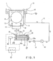
- a fluid heating apparatus in a first embodiment of the present invention and a cleaning system equipped with the fluid heating apparatus will be described with reference to Figs. 1, 2, 3A and 3B.
- the cleaning system includes: a cleaning tank 10 having an inner tank 11 that holds a cleaning liquid L, such as diluted hydrofluoric acid (DHF) or a rinse liquid (e.g., deionized water), and an outer tank 12 surrounding the upper opening of the inner tank 11 to receive the cleaning liquid overflowing from the inner tank 11; cleaning liquid supply nozzles 14 arranged at a lower area of the interior of the inner tank 11; a circulation passage 15 having a first end connected to the cleaning liquid supply nozzles 14 and a second end connected to a drain port 12a arranged at a bottom of the outer tank 12.
- a circulation pump 16, a filter 17 and a fluid heating apparatus 20 are arranged in the circulation passage 15 in that order from the drain-port 12a side.
- a wafer boat 13 is arranged in the inner tank 11 to hold a plurality of (e.g., 50pcs.) semiconductor wafers W (hereinafter simply referred to as "wafer").
- a drain pipe (not shown) provided thereon with a drain valve (not shown) is connected to a bottom of the inner tank 11.
- a cleaning liquid source (not shown) is arranged to supply a cleaning liquid L to the outer tank 12.
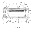
- the fluid heating apparatus 20 includes a tubular container 22, which may be formed of a stainless steel.
- a heat-insulating material is arranged on inner surfaces of the tubular container 22.
- a heating lamp typically a halogen lamp 23 is arranged in the tubular container 22 and extends along the longitudinal axis of the tubular container 22.
- a tubular structure 26 is arranged in the tubular container 22 to surround the halogen lamp 23 with an annular gap being formed between the halogen lamp 23 and the tubular structure 26.
- the tubular structure 26 has a fluid inlet 24 and a fluid outlet 25.
- the end openings of the tubular container 22 are respectively covered with end caps 22a and 22b each provided thereon with a heat-insulating material.
- the tubular structure 26 comprises a plurality of straight pipes 26a circumferentially arrayed around the halogen lamp 23 to be in a form of a tube.
- Each of the straight pipes 26a extends parallel to the halogen lamp 23.
- circumferentially adjacent pipes 26a are preferably in close contact with each other, but may be in close proximity while remaining a slight gap therebetween as long as leakage of radiant light (thermal radiation) emitted from the halogen lamp 23 to the exterior of the tubular structure 26 can be prevented or suppressed to a negligible level.
- At least a portion, facing the halogen lamp 23, of each pipe 26a is coated with a radiant-light-absorbing paint, typically a black paint 27. In the illustrated embodiment, the whole surface of each pipe 26a is coated with the black paint 27.
- each pipe 26a has a two-layer structure and thus includes an inner layer 28a and an outer layer 28b.
- the inner layer 28a is formed of a chemical -resistant material, specifically a synthetic resin such as polytetrafluoroethylene, which is not dissolved in hydrofluoric acid.
- the pipe 26a has an inner surface of a chemical-resistant synthetic resin.
- the outer layer 28b is formed of a heat-conductive material such as a metallic material (e.g., aluminum or a stainless steel).
- the black paint 27 is coated on the heat-conductive outer layer 28b.
- the black paint 27 efficiently absorbs radiant light (thermal radiation) emitted from the halogen lamp 23, so that the black paint 27 is heated efficiently.
- the heat is transferred from the black paint 27 to the inner layer 28a through the heat-conductive outer layer 28b uniformly.
- the fluid flowing through each pipe 26a can be heated uniformly and efficiently.
- each pipe 26a is respectively connected to ring-shaped manifolds 29a and 29b.
- the tubular structure 26 is composed of the pipes 26a and the manifolds 29a and 29b.
- the manifold 29a has a fluid inlet 24 serving as the fluid inlet of the tubular structure 26; and the manifold 29b has a fluid outlet 25 serving as the fluid outlet of the tubular structure 26.
- a part of the circulation passage 15 upstream of the tubular structure 26 connected to the filter 17 passes through one end of the tubular container 22 and is connected to the fluid inlet 24 of the manifold 29a; while a part of the circulation passage 15 downstream of the tubular structure 26 connected to the cleaning liquid nozzle 14 passes through the other end of the tubular container 22 and is connected to the fluid outlet 25 of the manifold 29b.
- a temperature sensor 30 Arranged near the fluid outlet 25 of the tubular structure 26 is a temperature sensor 30, which measures temperature of a cleaning liquid L flowing out of the fluid outlet 25.
- a power regulator 40 is electrically connected to the halogen lamp 23 to control calorific power generated by the halogen lamp 23.
- the temperature sensor 30 and the power regulator 40 are electrically connected to a central processing unit (CPU) 50. Temperature measured by the temperature sensor 30 is sent to the CPU 50, and the CPU 50 send a control signal to the power regulator 50, so that the temperature of the cleaning liquid L is controlled to coincide with a target temperature such as 80°C.
- a light-reflective member 60 may be arranged on the inner surface of the tubular container 22, as shown by chain-dotted lines in Fig. 2. Thus, radiant light emitted from the halogen light 23 and passed through gaps (if any) between adjacent pipes 26a is reflected by the light-reflective member 60 to fall on the outer surface of the tubular structure 26, so that the tubular structure 26 is more efficiently heated.
- the circulation pump 15 is driven, so that a cleaning liquid L overflowing from the inner tank 11 flows through the circulation passage 15 to be supplied into the tubular structure 26 through the fluid inlet 24.
- Radiant light emitted by the halogen lamp 23 is absorbed by the black paint 27 coated on each straight pipe 26a of the tubular structure 26, and the absorbed heat is transmitted to the whole inner surface of each straight pipe 26a uniformly.
- the cleaning liquid L flowing through each straight pipe 26a is heated up to a designated temperature such as 80 °C.
- the temperature of the cleaning liquid L is controlled by means of the temperature sensor 30, the power regulator 40 and the CPU 50 in the foregoing manner.
- the heated cleaning liquid L flows out of the tubular structure 26 through the fluid outlet 25, and is supplied to the cleaning liquid supply nozzles 14 to be jetted therefrom toward the wafers W held in the inner tank 11.
- the tubular structure 26A comprises a single pipe 70, which is wound in a spiral configuration around the heating lamp 23 to be in a form of a tube.
- the tubular structure 26A surrounds the halogen lamp 23 with an annular gap being formed between the halogen lamp 23 and the tubular structure 26A.
- the spiral axis of the pipe 70 coincides with the longitudinal axis of the halogen lamp 23.
- adjacent portions of the pipe 70 with respect to the spiral-axis direction are preferably in close contact with each other, but may be in close proximity while remaining a slight gap therebetween as long as leakage of radiant light emitted from the halogen lamp 23 to the exterior of the tubular structure 26A can be prevented or suppressed to a negligible level.
- the pipe 70 has one end portion thereof serving as a fluid inlet 24 of the tubular structure 26A and extending straightly through the end cap 22a, and the other end portion thereof serving as a fluid outlet 25 of the tubular structure 26A and extending straightly through the end cap 22b.
- the cross-sectional structure of the spiral pipe 70 is essentially the same as that of the straight pipe 26a in the first embodiment, and thus the description thereof is omitted.
- the cleaning liquid L flown into the tubular structure 26A through the fluid inlet 24 is heated by the radiant light emitted from the halogen lamp in a manner essentially the same as that in the first embodiment, and flows out of the tubular structure 26A through the fluid outlet 25.
- the elements designated by the same reference numerals in Figs. 1, 2, 3A and 3B are the same as those in Figs. 1, 2, 3A and 3B, and thus the description thereof is omitted.
- the fluid heating apparatus may be applied to a cleaning system for cleaning a process object other than a semiconductor wafer, such as a glass substrate for an LCD (liquid crystal display).
- the fluid to be heated by the fluid heating apparatus is not limited to DHF, or a fluid in liquid state.
- the fluid may be a gaseous fluid or a misty fluid.
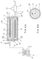
- Figs. 6A, 6B, 7A and 7B show an IPA drying system for drying semiconductor wafers by using a mixed gas of IPA vapor and N 2 gas, which is equipped with a fluid heating apparatus 20B in the third embodiment of the present invention.
- the IPA drying system includes: a process container 80 adapted to accommodate semiconductor wafers W (i.e., process objects) therein; a fluid supply nozzle 81 for jetting a mixed gas of IPA vapor and N 2 gas toward the semiconductor wafers W accommodated in the process container 80; a fluid heating apparatus 20B in a third embodiment according to the present invention; and a two-fluid nozzle 82 for atomizing IPA liquid by using N 2 gas.
- the fluid heating apparatus 20B in the third embodiment differs from the fluid heating apparatus 20A in the second embodiment only in the following respects.
- the cross-sectional structure of the spiral pipe 70A of the fluid heating apparatus 20B is different from that of the spiral pipe 70 of the fluid heating apparatus 20A.
- the spiral pipe 70A has a single-layer structure, and comprises a stainless pipe which itself has a good thermal conductivity. As IPA is not corrosive, the provision of an inner layer made of a chemical resistant synthetic resin is not necessary (but may be provided).
- the black paint 27 is coated on the stainless pipe (see Fig. 7B).
- One end of the spiral pipe 70A serving as a fluid inlet 24 of the tubular structure is connected to an outlet port 83 of the two-fluid nozzle 82.
- the tubular container 21 of the fluid heating apparatus 20B is further provided at the end cap thereof with a purge gas supply port 86.
- N 2 gas i.e., inert gas
- N 2 gas is supplied into the tubular container 21 through the purge gas supply port 86, whereby the interior of the tubular container 21 can be purged, preventing a flammable or volatile fluid (such as IPA vapor) from penetrating into the interior of the tubular container 21, achieving a safer operation of the fluid heating apparatus 20B.
- a mixed fluid of atomized IPA and N 2 gas flows into the spiral pipe 70A of the fluid heating apparatus 20B, where the atomized IPA is vaporized, and thus a mixed gaseous fluid of IPA vapor and N 2 gas flows out of the fluid heating apparatus 20B.
- the mixed gaseous fluid of IPA vapor and N 2 gas is supplied to the fluid supply nozzle 81 and is jetted thereform toward the semiconductor wafers W to dry the same.
- the fluid heating apparatus 20B is capable of heating a fluid efficiently.
- Figs. 6A, 6B, 7A and 7B the elements designated by the same reference numerals in Figs. 4A, 4B, 5A and 5B are the same as those in Figs. 4A, 4B, 5A and 5B, and thus the description thereof is omitted.
- the third embodiment may be modified by substituting the tubing structure comprising plural straight pipes 20a of the first embodiment with the spiral pipe 70A of the tubing structure 20B.
- Two or more fluid heating apparatuses 20B may be connected in series.
- the upstream-side fluid heating apparatus 20B may heat the fluid to vaporize the same, and the downstream-side fluid heating apparatus 20B may heat the vaporized fluid to a designated process temperature.
- the halogen lamp 23 may be replaced with another sort of thermal-radiating lamp, such as an infrared lamp.
Landscapes
- Engineering & Computer Science (AREA)
- Physics & Mathematics (AREA)
- Thermal Sciences (AREA)
- Mechanical Engineering (AREA)
- General Engineering & Computer Science (AREA)
- Chemical & Material Sciences (AREA)
- Combustion & Propulsion (AREA)
- Instantaneous Water Boilers, Portable Hot-Water Supply Apparatuses, And Control Of Portable Hot-Water Supply Apparatuses (AREA)
- Cleaning Or Drying Semiconductors (AREA)
- Resistance Heating (AREA)
- Weting (AREA)
- Exposure Of Semiconductors, Excluding Electron Or Ion Beam Exposure (AREA)
Abstract
Description
- The present invention relates to a fluid heating apparatus, and more specifically to a fluid heating apparatus that heats a flowing fluid by thermal radiation emitted from a heating lamp.
- A semiconductor device fabricating process includes a fluid treatment that brings a process object, such as a semiconductor wafer, into contact with a processing fluid to treat the process object. In one example of the fluid treatment, the process object is immersed in a processing fluid, such as diluted hydrofluoric acid (DHF) or a rinse liquid, held in a cleaning tank in order to clean the process object. In another example of the fluid treatment, a mixed gaseous fluid of vaporized isopropyl alcohol (IPA) and nitrogen gas (N2 gas) is supplied to a process object to dry the same. In general, the temperature of the processing fluid must be regulated at a designated target temperature in order to achieve the desired process result. To this end, a fluid heating apparatus for regulating the temperature of the processing fluid is employed.
-
JP09-210577A - In general, a fluid heating apparatus of the foregoing direct-heating type has some problems. First, if the thermal-radiation absorption of the fluid is high, the fluid flowing through an area, remote from the heating lamp, in the fluid-flowing space is not sufficiently heated, while the fluid flowing through an area, near the heating lamp, in the fluid-flowing space is efficiently heated. Thus, sufficient heating efficiency can not be achieved. If the fluid is a flammable or volatile organic solvent such as IPA, the fluid must be heated with particular attention on the temperature control.
- The fluid heating apparatus of
JP09-210577A - As mentioned above, in a fluid heating apparatus of the foregoing direct-heating type, the transparent tube surrounding the heating lamp is typically made of quartz. If the fluid to be heated is DHF, the quartz material contacting with the fluid will be dissolved therein, and thus cannot be used.
- The present invention has been made in view of the forgoing problems, and therefore the main object of the present invention is to provide a fluid heating apparatus which is capable of effectively and uniformly heating a fluid, and which can be fabricated at a reasonable cost. Preferably, the fluid heating apparatus can heat any sort of fluid.
- In order to achieve the above objective, the present invention provides a fluid heating apparatus, which includes: a heating lamp; and a tubular structure having a fluid inlet allowing the fluid to be heated to flow into the tubular structure and a fluid outlet allowing the fluid having been heated to flow out of the tubular structure, wherein the tubular structure comprises at least one pipe arranged in a form of a tube surrounding the heating lamp, and at least a surface, facing the heating lamp, of the tubular structure is coated with a radiant-light-absorbing paint.
- According to the present invention, the radiant-light-absorbing paint efficiently absorbs thermal radiation emitted from the heating lamp, the pipe is heated efficiently, and thus the fluid flowing through the pipe is heated efficiently through the heat transfer from the pipe to the fluid. The fluid is thus efficiently heated regardless of the sort of the fluid, or the thermal-radiation absorption of the fluid.
- Each of said at least one pipe may have an inner surface formed of a chemical-resistant synthetic resin. In this case, preferably, each of said at least one pipe may have a heat-conductive layer formed of a heat-conductive material, and the radiant-light-absorbing paint may be coated on the heat-conductive layer.
- As the inner surface is formed of the chemical-resistant synthetic resin, a corrosive fluid can be heated without damaging the pipe. If the heat-conductive layer is provided, the heat generated in the radiant-light-absorbing paint due to the absorption of the thermal radiation is uniformly transferred to and distributed over the inner surface formed of the chemical-resistant synthetic resin through the heat-conductive layer, and thus the fluid can be heated uniformly, even if the inner surface is formed of the chemical-resistant synthetic resin having relatively low heat conductivity.
- In one preferable embodiment, the tubular structure may comprise a plurality of straight pipes circumferentially arrayed around the heating lamp. In another preferable embodiment, the tubular structure may comprise a single pipe wound in a spiral configuration around the heating lamp.
- The fluid heating apparatus may further include a tubular container accommodating the heating lamp and the tubular structure. The tubular container may have a light-reflective inner surface.
- Due to the provision of the tubular container, dissipation of the thermal energy generated by the heating lamp can be suppressed, improving the heating efficiency. As the radiant light emitted from the heating lamp and leaked through gaps (if any) in the tubular structure is reflected by the light-reflective inner surface of the tubular container to fall on the outer surface of the tubular structure, the fluid can be heated more efficiently.
- The fluid heating apparatus may further include an inert gas supply adapted to supply an inert gas into an interior of the tubular container. This configuration prevents penetration of external atmosphere into the tubular container, and achieves safer operation of the fluid heating apparatus.
- The fluid heating apparatus may further include: a temperature sensor adapted to detect temperature of a fluid flowing through the tubular structure; a power supply adapted to regulate electric power to be supplied to the heating lamp, thereby to control calorific power generated by the heating lamp; a controller configured to generate a control signal based on the temperature detected by the temperature sensor and send the control signal to the power supply so that the temperature of the fluid coincides with a target value.
-
- Fig. 1 is a schematic diagram showing the whole structure of a cleaning system equipped with a fluid heating apparatus in a first embodiment of the present invention;
- Fig. 2 is a longitudinal cross-sectional view of the fluid heating apparatus in the first embodiment of the present invention;
- Fig. 3A is a transverse cross-sectional view of the fluid heating apparatus taken along line IIIA-IIIA in Fig. 2;
- Fig. 3B is an enlarged view of area IIIB in Fig. 3A;
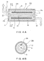
- Fig. 4A is a longitudinal cross-sectional view of a fluid heating apparatus in a second embodiment of the present invention;
- Fig. 4B is a transverse cross-sectional view of the fluid heating apparatus taken along line IVB-IVB in Fig. 4A;
- Fig. 5A is an enlarged view of the lamp and the pipe shown in Fig. 4A;
- Fig. 5B is an enlarged view of area VB in Fig. 5A;
- Fig. 6A is a schematic diagram showing the structure of an IPA drying system equipped with a fluid heating apparatus in a third embodiment of the present invention;
- Fig. 6B is a cross sectional view of the heating apparatus taken along line VIB-VIB in Fig. 6A;
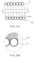
- Fig. 7A is an enlarged view of the lamp and the pipe shown in Fig. 6A; and
- Fig. 7B is an enlarged view of area VIIB in Fig. 7A.
- A fluid heating apparatus in a first embodiment of the present invention and a cleaning system equipped with the fluid heating apparatus will be described with reference to Figs. 1, 2, 3A and 3B.
- Referring to Fig. 1, the cleaning system includes: a cleaning
tank 10 having aninner tank 11 that holds a cleaning liquid L, such as diluted hydrofluoric acid (DHF) or a rinse liquid (e.g., deionized water), and anouter tank 12 surrounding the upper opening of theinner tank 11 to receive the cleaning liquid overflowing from theinner tank 11; cleaningliquid supply nozzles 14 arranged at a lower area of the interior of theinner tank 11; acirculation passage 15 having a first end connected to the cleaningliquid supply nozzles 14 and a second end connected to adrain port 12a arranged at a bottom of theouter tank 12. Acirculation pump 16, afilter 17 and afluid heating apparatus 20 are arranged in thecirculation passage 15 in that order from the drain-port 12a side. Awafer boat 13 is arranged in theinner tank 11 to hold a plurality of (e.g., 50pcs.) semiconductor wafers W (hereinafter simply referred to as "wafer"). A drain pipe (not shown) provided thereon with a drain valve (not shown) is connected to a bottom of theinner tank 11. A cleaning liquid source (not shown) is arranged to supply a cleaning liquid L to theouter tank 12. - Referring to Figs. 2, 3A and 3B, the
fluid heating apparatus 20 includes atubular container 22, which may be formed of a stainless steel. A heat-insulating material is arranged on inner surfaces of thetubular container 22. A heating lamp, typically ahalogen lamp 23, is arranged in thetubular container 22 and extends along the longitudinal axis of thetubular container 22. Atubular structure 26 is arranged in thetubular container 22 to surround thehalogen lamp 23 with an annular gap being formed between thehalogen lamp 23 and thetubular structure 26. Thetubular structure 26 has afluid inlet 24 and afluid outlet 25. The end openings of thetubular container 22 are respectively covered withend caps - In the first embodiment, the
tubular structure 26 comprises a plurality ofstraight pipes 26a circumferentially arrayed around thehalogen lamp 23 to be in a form of a tube. Each of thestraight pipes 26a extends parallel to thehalogen lamp 23. In view of heating efficiency, circumferentiallyadjacent pipes 26a are preferably in close contact with each other, but may be in close proximity while remaining a slight gap therebetween as long as leakage of radiant light (thermal radiation) emitted from thehalogen lamp 23 to the exterior of thetubular structure 26 can be prevented or suppressed to a negligible level. At least a portion, facing thehalogen lamp 23, of eachpipe 26a is coated with a radiant-light-absorbing paint, typically ablack paint 27. In the illustrated embodiment, the whole surface of eachpipe 26a is coated with theblack paint 27. - As shown in Figs. 3A and 3B, each
pipe 26a has a two-layer structure and thus includes aninner layer 28a and anouter layer 28b. Theinner layer 28a is formed of a chemical -resistant material, specifically a synthetic resin such as polytetrafluoroethylene, which is not dissolved in hydrofluoric acid. Thus, thepipe 26a has an inner surface of a chemical-resistant synthetic resin. Theouter layer 28b is formed of a heat-conductive material such as a metallic material (e.g., aluminum or a stainless steel). Theblack paint 27 is coated on the heat-conductiveouter layer 28b. - Due to the foregoing structure, the
black paint 27 efficiently absorbs radiant light (thermal radiation) emitted from thehalogen lamp 23, so that theblack paint 27 is heated efficiently. The heat is transferred from theblack paint 27 to theinner layer 28a through the heat-conductiveouter layer 28b uniformly. Thus, the fluid flowing through eachpipe 26a can be heated uniformly and efficiently. - The both ends of each
pipe 26a are respectively connected to ring-shapedmanifolds tubular structure 26 is composed of thepipes 26a and themanifolds fluid inlet 24 serving as the fluid inlet of thetubular structure 26; and the manifold 29b has afluid outlet 25 serving as the fluid outlet of thetubular structure 26. A part of thecirculation passage 15 upstream of thetubular structure 26 connected to thefilter 17 passes through one end of thetubular container 22 and is connected to thefluid inlet 24 of the manifold 29a; while a part of thecirculation passage 15 downstream of thetubular structure 26 connected to the cleaningliquid nozzle 14 passes through the other end of thetubular container 22 and is connected to thefluid outlet 25 of the manifold 29b. - Arranged near the
fluid outlet 25 of thetubular structure 26 is atemperature sensor 30, which measures temperature of a cleaning liquid L flowing out of thefluid outlet 25. Apower regulator 40 is electrically connected to thehalogen lamp 23 to control calorific power generated by thehalogen lamp 23. Thetemperature sensor 30 and thepower regulator 40 are electrically connected to a central processing unit (CPU) 50. Temperature measured by thetemperature sensor 30 is sent to theCPU 50, and theCPU 50 send a control signal to thepower regulator 50, so that the temperature of the cleaning liquid L is controlled to coincide with a target temperature such as 80°C. - A light-
reflective member 60 may be arranged on the inner surface of thetubular container 22, as shown by chain-dotted lines in Fig. 2. Thus, radiant light emitted from thehalogen light 23 and passed through gaps (if any) betweenadjacent pipes 26a is reflected by the light-reflective member 60 to fall on the outer surface of thetubular structure 26, so that thetubular structure 26 is more efficiently heated. - In operation, the
circulation pump 15 is driven, so that a cleaning liquid L overflowing from theinner tank 11 flows through thecirculation passage 15 to be supplied into thetubular structure 26 through thefluid inlet 24. Radiant light emitted by thehalogen lamp 23 is absorbed by theblack paint 27 coated on eachstraight pipe 26a of thetubular structure 26, and the absorbed heat is transmitted to the whole inner surface of eachstraight pipe 26a uniformly. Thus, the cleaning liquid L flowing through eachstraight pipe 26a is heated up to a designated temperature such as 80 °C. The temperature of the cleaning liquid L is controlled by means of thetemperature sensor 30, thepower regulator 40 and theCPU 50 in the foregoing manner. The heated cleaning liquid L flows out of thetubular structure 26 through thefluid outlet 25, and is supplied to the cleaningliquid supply nozzles 14 to be jetted therefrom toward the wafers W held in theinner tank 11. - The fluid heating apparatus in a second embodiment of the present invention will be described with reference to Figs. 4A, 4B, 5A and 5B.
- In the second embodiment of the
fluid heating apparatus 20A, thetubular structure 26A comprises asingle pipe 70, which is wound in a spiral configuration around theheating lamp 23 to be in a form of a tube. Thetubular structure 26A surrounds thehalogen lamp 23 with an annular gap being formed between thehalogen lamp 23 and thetubular structure 26A. The spiral axis of thepipe 70 coincides with the longitudinal axis of thehalogen lamp 23. In view of the heating efficiency, adjacent portions of thepipe 70 with respect to the spiral-axis direction are preferably in close contact with each other, but may be in close proximity while remaining a slight gap therebetween as long as leakage of radiant light emitted from thehalogen lamp 23 to the exterior of thetubular structure 26A can be prevented or suppressed to a negligible level. Thepipe 70 has one end portion thereof serving as afluid inlet 24 of thetubular structure 26A and extending straightly through theend cap 22a, and the other end portion thereof serving as afluid outlet 25 of thetubular structure 26A and extending straightly through theend cap 22b. - The cross-sectional structure of the
spiral pipe 70 is essentially the same as that of thestraight pipe 26a in the first embodiment, and thus the description thereof is omitted. Also in the second embodiment, the cleaning liquid L flown into thetubular structure 26A through thefluid inlet 24 is heated by the radiant light emitted from the halogen lamp in a manner essentially the same as that in the first embodiment, and flows out of thetubular structure 26A through thefluid outlet 25. In Figs. 4A, 4B, 5A and 5B, the elements designated by the same reference numerals in Figs. 1, 2, 3A and 3B are the same as those in Figs. 1, 2, 3A and 3B, and thus the description thereof is omitted. - Although the foregoing description has been made for embodiments in which the fluid heating apparatus is applied to a semiconductor wafer cleaning system, the fluid heating apparatus may be applied to a cleaning system for cleaning a process object other than a semiconductor wafer, such as a glass substrate for an LCD (liquid crystal display). The fluid to be heated by the fluid heating apparatus is not limited to DHF, or a fluid in liquid state. The fluid may be a gaseous fluid or a misty fluid.
- Figs. 6A, 6B, 7A and 7B show an IPA drying system for drying semiconductor wafers by using a mixed gas of IPA vapor and N2 gas, which is equipped with a
fluid heating apparatus 20B in the third embodiment of the present invention. The IPA drying system includes: aprocess container 80 adapted to accommodate semiconductor wafers W (i.e., process objects) therein; afluid supply nozzle 81 for jetting a mixed gas of IPA vapor and N2 gas toward the semiconductor wafers W accommodated in theprocess container 80; afluid heating apparatus 20B in a third embodiment according to the present invention; and a two-fluid nozzle 82 for atomizing IPA liquid by using N2 gas. - The
fluid heating apparatus 20B in the third embodiment differs from thefluid heating apparatus 20A in the second embodiment only in the following respects. - First, the cross-sectional structure of the
spiral pipe 70A of thefluid heating apparatus 20B is different from that of thespiral pipe 70 of thefluid heating apparatus 20A. Thespiral pipe 70A has a single-layer structure, and comprises a stainless pipe which itself has a good thermal conductivity. As IPA is not corrosive, the provision of an inner layer made of a chemical resistant synthetic resin is not necessary (but may be provided). Theblack paint 27 is coated on the stainless pipe (see Fig. 7B). One end of thespiral pipe 70A serving as afluid inlet 24 of the tubular structure is connected to anoutlet port 83 of the two-fluid nozzle 82. - Second, the
tubular container 21 of thefluid heating apparatus 20B is further provided at the end cap thereof with a purgegas supply port 86. N2 gas (i.e., inert gas) is supplied into thetubular container 21 through the purgegas supply port 86, whereby the interior of thetubular container 21 can be purged, preventing a flammable or volatile fluid (such as IPA vapor) from penetrating into the interior of thetubular container 21, achieving a safer operation of thefluid heating apparatus 20B. - In operation, a mixed fluid of atomized IPA and N2 gas flows into the
spiral pipe 70A of thefluid heating apparatus 20B, where the atomized IPA is vaporized, and thus a mixed gaseous fluid of IPA vapor and N2 gas flows out of thefluid heating apparatus 20B. The mixed gaseous fluid of IPA vapor and N2 gas is supplied to thefluid supply nozzle 81 and is jetted thereform toward the semiconductor wafers W to dry the same. Also in this embodiment, thefluid heating apparatus 20B is capable of heating a fluid efficiently. - In Figs. 6A, 6B, 7A and 7B, the elements designated by the same reference numerals in Figs. 4A, 4B, 5A and 5B are the same as those in Figs. 4A, 4B, 5A and 5B, and thus the description thereof is omitted.
- The third embodiment may be modified by substituting the tubing structure comprising plural straight pipes 20a of the first embodiment with the
spiral pipe 70A of thetubing structure 20B. - Two or more
fluid heating apparatuses 20B may be connected in series. In this case, the upstream-sidefluid heating apparatus 20B may heat the fluid to vaporize the same, and the downstream-sidefluid heating apparatus 20B may heat the vaporized fluid to a designated process temperature. - In the foregoing embodiments, the
halogen lamp 23 may be replaced with another sort of thermal-radiating lamp, such as an infrared lamp.
Claims (9)
- A fluid heating apparatus comprising:a heating lamp; anda tubular structure having a fluid inlet allowing the fluid to be heated to flow into the tubular structure and a fluid outlet allowing the fluid having been heated to flow out of the tubular structure, wherein the tubular structure comprises at least one pipe arranged in a form of a tube surrounding the heating lamp, and at least a surface, facing the heating lamp, of the tubular structure is coated with a radiant-light-absorbing paint.
- The fluid heating apparatus according to claim 1, wherein each of said at least one pipe has an inner surface formed of a chemical-resistant synthetic resin.
- The fluid heating apparatus according to claim 2, wherein each of said at least one pipe has a heat-conductive layer formed of a heat-conductive material, and the radiant-light-absorbing paint is coated on the heat-conductive layer.
- The fluid heating apparatus according to claim 1, wherein the tubular structure comprises a plurality of straight pipes circumferentially arrayed around the heating lamp.
- The fluid heating apparatus according to claim 1, wherein the tubular structure comprises a single pipe wound in a spiral configuration around the heating lamp.
- The fluid heating apparatus according to any one of claims 1 to 5, further comprising a tubular container accommodating the heating lamp and the tubular structure.
- The fluid heating apparatus according to claim 6, wherein the tubular container has a light-reflective inner surface.
- The fluid heating apparatus according to claim 6, further comprising an inert gas supply adapted to supply an inert gas into an interior of the tubular container.
- The fluid heating apparatus according to any one of claims 1 to 8, further comprising:a temperature sensor adapted to detect temperature of a fluid flowing through the tubular structure;a power supply adapted to regulate electric power to be supplied to the heating lamp, thereby to control calorific power generated by the heating lamp; anda controller configured to generate a control signal based on the temperature detected by the temperature sensor and send the control signal to the power supply so that the temperature of the fluid coincides with a target value.
Applications Claiming Priority (1)
| Application Number | Priority Date | Filing Date | Title |
|---|---|---|---|
| JP2005199899A JP4743495B2 (en) | 2005-07-08 | 2005-07-08 | Fluid heating device |
Publications (2)
| Publication Number | Publication Date |
|---|---|
| EP1741995A2 true EP1741995A2 (en) | 2007-01-10 |
| EP1741995A3 EP1741995A3 (en) | 2007-08-01 |
Family
ID=37124282
Family Applications (1)
| Application Number | Title | Priority Date | Filing Date |
|---|---|---|---|
| EP06014160A Withdrawn EP1741995A3 (en) | 2005-07-08 | 2006-07-07 | Fluid heating apparatus |
Country Status (6)
| Country | Link |
|---|---|
| US (1) | US7593625B2 (en) |
| EP (1) | EP1741995A3 (en) |
| JP (1) | JP4743495B2 (en) |
| KR (1) | KR101123994B1 (en) |
| CN (1) | CN100554760C (en) |
| TW (1) | TW200716923A (en) |
Cited By (2)
| Publication number | Priority date | Publication date | Assignee | Title |
|---|---|---|---|---|
| EP2112438A3 (en) * | 2008-04-24 | 2012-06-13 | D.H.E. S.R.L. | Heat exchanger for fluids |
| IT202200005471A1 (en) * | 2022-03-21 | 2023-09-21 | Rudi Foini | NEBULIZATION DEVICE AND ABBREVIATE HEAT EXCHANGE METHOD FOR VAPORIZATION OF LIQUID SUBSTANCE |
Families Citing this family (37)
| Publication number | Priority date | Publication date | Assignee | Title |
|---|---|---|---|---|
| JP2008244318A (en) * | 2007-03-28 | 2008-10-09 | Tokyo Electron Ltd | Substrate transport member cleaning method, substrate transport apparatus, and substrate processing system |
| JP5184631B2 (en) * | 2008-06-02 | 2013-04-17 | 東京エレクトロン株式会社 | Fluid heater, manufacturing method thereof, substrate processing apparatus provided with fluid heater, and substrate processing method |
| JP5138515B2 (en) | 2008-09-05 | 2013-02-06 | 東京エレクトロン株式会社 | Steam generator, steam generating method and substrate processing apparatus |
| JP5415797B2 (en) * | 2009-03-24 | 2014-02-12 | 株式会社Kelk | Fluid heating device |
| JP2011075145A (en) * | 2009-09-29 | 2011-04-14 | Fuji Heavy Ind Ltd | Fluid heating device and circulation type heating treatment system using the same |
| DE102010011702A1 (en) | 2010-03-10 | 2011-09-15 | E.G.O. Elektro-Gerätebau GmbH | Unit, particularly steam generator for heating of water or steam, particularly for generation of steam with temperature of more than one hundred degree Celsius, has coiled or curved or spiral water circuit with water inlet and steam outlet |
| CN201839457U (en) * | 2010-05-24 | 2011-05-18 | 小田(中山)实业有限公司 | Heaters and instant electric water heaters |
| JP5307780B2 (en) * | 2010-09-13 | 2013-10-02 | 東京エレクトロン株式会社 | Liquid heating unit, liquid processing apparatus including the same, and liquid processing method |
| KR101036509B1 (en) * | 2010-09-30 | 2011-05-24 | 정광호 | Apparatus for making hot water using carbon heater |
| JP2012087983A (en) * | 2010-10-19 | 2012-05-10 | Tokyo Electron Ltd | Fluid heating device and substrate processing apparatus |
| JP2012189385A (en) * | 2011-03-09 | 2012-10-04 | Fujifilm Corp | Maintenance method of radiograph detection apparatus |
| DE102011013810B4 (en) * | 2011-03-14 | 2022-03-03 | Stiebel Eltron Gmbh & Co. Kg | Electronically controlled instantaneous water heater and method for operating an electronically controlled instantaneous water heater |
| US10222091B2 (en) | 2012-07-17 | 2019-03-05 | Eemax, Inc. | Next generation modular heating system |
| US9140466B2 (en) | 2012-07-17 | 2015-09-22 | Eemax, Inc. | Fluid heating system and instant fluid heating device |
| US9234674B2 (en) * | 2012-12-21 | 2016-01-12 | Eemax, Inc. | Next generation bare wire water heater |
| JP6244529B2 (en) * | 2013-03-05 | 2017-12-13 | 国立研究開発法人農業・食品産業技術総合研究機構 | Heating medium generator and heat treatment apparatus including the heating medium generator |
| US10264629B2 (en) * | 2013-05-30 | 2019-04-16 | Osram Sylvania Inc. | Infrared heat lamp assembly |
| JP6021767B2 (en) * | 2013-09-04 | 2016-11-09 | 日本サーモスタット株式会社 | Heater device for heating liquefied gas |
| KR101522714B1 (en) * | 2014-01-14 | 2015-06-17 | 주식회사 미니맥스 | Decompressing apparatus for semiconductor and liquid crystal display manufacturing equipment |
| US9451792B1 (en) * | 2014-09-05 | 2016-09-27 | Atmos Nation, LLC | Systems and methods for vaporizing assembly |
| AU2015364502B2 (en) | 2014-12-17 | 2017-12-14 | Rheem Manufacturing Company | Tankless electric water heater |
| EP3300102B1 (en) * | 2015-05-22 | 2019-04-17 | FUJI Corporation | Electronic component pressure-bonding device and electronic component mounting machine |
| CN106288332B (en) * | 2015-06-08 | 2019-03-22 | 福建斯狄渢电开水器有限公司 | an instant heater |
| TW201829961A (en) * | 2016-10-25 | 2018-08-16 | 伊馬德 馬哈維利 | Steam generator and reactor |
| KR101837891B1 (en) * | 2017-02-22 | 2018-03-13 | 이우주 | liquid circulation type double pipe lamp |
| KR101846509B1 (en) * | 2017-03-29 | 2018-04-09 | (주)앤피에스 | Heater and substrate processing apparatus having the same |
| JP6961211B2 (en) * | 2017-07-20 | 2021-11-05 | メトロ電気工業株式会社 | Fluid heater |
| JP2020009628A (en) * | 2018-07-09 | 2020-01-16 | 有限会社フィンテック | Light heating type heater |
| JP2020064764A (en) * | 2018-10-17 | 2020-04-23 | シャープ株式会社 | Fluid heating device, cooking device |
| JP7190888B2 (en) * | 2018-12-06 | 2022-12-16 | 東京エレクトロン株式会社 | Piping heating device and substrate processing device |
| EP4066591A4 (en) * | 2019-11-26 | 2024-02-28 | NxStage Medical, Inc. | HEATING DEVICES, METHODS AND SYSTEMS |
| KR102089228B1 (en) * | 2019-12-05 | 2020-03-13 | 신영현 | Lighting water heater |
| US11705345B2 (en) | 2020-04-30 | 2023-07-18 | Edwards Vacuum Llc | Semiconductor system with steam generator and reactor |
| KR20240164573A (en) * | 2022-03-24 | 2024-11-19 | 화이트 나이트 플루이드 핸들링 인크. | Fluid heater |
| CN115440626B (en) * | 2022-08-30 | 2024-11-26 | 浙江大学 | A high-efficiency and high-precision infrared quartz heater |
| CN121795137A (en) * | 2023-09-15 | 2026-04-03 | 东京毅力科创株式会社 | Fluid supply system, substrate processing apparatus, and substrate processing method |
| WO2025207004A1 (en) * | 2024-03-25 | 2025-10-02 | Kanthal Ab | Fluid guiding module fluid heater and fluid heating apparatus |
Family Cites Families (23)
| Publication number | Priority date | Publication date | Assignee | Title |
|---|---|---|---|---|
| US1767122A (en) * | 1929-07-03 | 1930-06-24 | Charles G Dean | Portable electric water heater |
| US3546431A (en) * | 1969-04-25 | 1970-12-08 | Erich L Gibbs | Immersion heater and method of making the same |
| US5054107A (en) * | 1989-05-19 | 1991-10-01 | Geoffrey Batchelder | Radiating lamp fluid heating system |
| GB8919700D0 (en) | 1989-08-31 | 1989-10-11 | Electricity Council | Infra-red radiation emission arrangement |
| JPH0342637U (en) * | 1989-09-01 | 1991-04-23 | ||
| US5127465A (en) * | 1990-12-28 | 1992-07-07 | Fischer Industries, Inc. | Heat exchanger |
| JP2583159B2 (en) * | 1991-02-08 | 1997-02-19 | 株式会社小松製作所 | Fluid heater |
| JPH06221677A (en) * | 1993-01-22 | 1994-08-12 | Nishibori Minoru | Gas heater |
| JP3501887B2 (en) * | 1995-09-29 | 2004-03-02 | 小松エレクトロニクス株式会社 | Fluid heating device |
| JP3033047B2 (en) * | 1995-11-30 | 2000-04-17 | 株式会社小松製作所 | Fluid temperature controller |
| JPH1024102A (en) * | 1996-07-15 | 1998-01-27 | Meteku:Kk | Heater for heating dialysis liquid |
| JPH10220909A (en) | 1996-12-03 | 1998-08-21 | Komatsu Ltd | Fluid temperature control device |
| JP3847469B2 (en) * | 1998-10-02 | 2006-11-22 | 小松エレクトロニクス株式会社 | Fluid heating device |
| JP2000111155A (en) * | 1998-10-02 | 2000-04-18 | Komatsu Electronics Kk | Liquid heater |
| JP2000146298A (en) * | 1998-11-13 | 2000-05-26 | Matsushita Electric Ind Co Ltd | Catalytic combustion device |
| JP3963610B2 (en) * | 1999-04-20 | 2007-08-22 | 三益半導体工業株式会社 | Liquid heating device |
| JP3587249B2 (en) * | 2000-03-30 | 2004-11-10 | 東芝セラミックス株式会社 | Fluid heating device |
| JP2002162113A (en) * | 2000-11-24 | 2002-06-07 | Ses Co Ltd | Temperature increasing device for constant temperature liquid |
| AU2002313719A1 (en) | 2001-08-03 | 2003-02-24 | Integrated Circuit Development Corporation | In-line fluid heating system |
| JP2003090613A (en) * | 2001-09-18 | 2003-03-28 | Komatsu Electronics Inc | Fluid heating device |
| JP2003097849A (en) * | 2001-09-25 | 2003-04-03 | Orion Mach Co Ltd | Fluid heating device |
| JP3936644B2 (en) * | 2002-08-29 | 2007-06-27 | ニチアス株式会社 | Fluid heating device |
| AU2003296942A1 (en) * | 2002-12-11 | 2004-06-30 | Thomas Johnston | Method device for heating fluids |
-
2005
- 2005-07-08 JP JP2005199899A patent/JP4743495B2/en not_active Expired - Lifetime
-
2006
- 2006-06-29 KR KR1020060059168A patent/KR101123994B1/en active Active
- 2006-07-06 US US11/481,253 patent/US7593625B2/en active Active
- 2006-07-07 CN CNB2006101054930A patent/CN100554760C/en active Active
- 2006-07-07 EP EP06014160A patent/EP1741995A3/en not_active Withdrawn
- 2006-07-07 TW TW095124856A patent/TW200716923A/en unknown
Cited By (2)
| Publication number | Priority date | Publication date | Assignee | Title |
|---|---|---|---|---|
| EP2112438A3 (en) * | 2008-04-24 | 2012-06-13 | D.H.E. S.R.L. | Heat exchanger for fluids |
| IT202200005471A1 (en) * | 2022-03-21 | 2023-09-21 | Rudi Foini | NEBULIZATION DEVICE AND ABBREVIATE HEAT EXCHANGE METHOD FOR VAPORIZATION OF LIQUID SUBSTANCE |
Also Published As
| Publication number | Publication date |
|---|---|
| EP1741995A3 (en) | 2007-08-01 |
| KR101123994B1 (en) | 2012-03-23 |
| TW200716923A (en) | 2007-05-01 |
| JP4743495B2 (en) | 2011-08-10 |
| CN1892094A (en) | 2007-01-10 |
| TWI297762B (en) | 2008-06-11 |
| KR20070006558A (en) | 2007-01-11 |
| US20070017502A1 (en) | 2007-01-25 |
| US7593625B2 (en) | 2009-09-22 |
| JP2007017098A (en) | 2007-01-25 |
| CN100554760C (en) | 2009-10-28 |
Similar Documents
| Publication | Publication Date | Title |
|---|---|---|
| US7593625B2 (en) | Fluid heating apparatus | |
| KR101357056B1 (en) | Fluid heating device | |
| US9485807B2 (en) | Liquid heating apparatus and liquid heating method | |
| EP0570586A1 (en) | Fluid heater | |
| TWI506673B (en) | Vaporization device, substrate processing device, coating and developing device, and substrate processing method | |
| CN113130357B (en) | Wafer drying system and wafer drying method | |
| US6621984B2 (en) | In-line fluid heating system | |
| US5054108A (en) | Heater and method for deionized water and other liquids | |
| US7637029B2 (en) | Vapor drying method, apparatus and recording medium for use in the method | |
| CN110023689A (en) | Steam generator and reactor | |
| US20220136733A1 (en) | Film type liquid heater and uniform heating method thereof | |
| CN1911489B (en) | Steam drying method and device | |
| JP2008096057A (en) | Liquid heating device | |
| KR102346370B1 (en) | Apparatus for heating chemical and the method thereof | |
| CN211904476U (en) | Temperature detection device | |
| JP7323674B1 (en) | Chemical liquid heating device and substrate processing system provided with same | |
| KR102220163B1 (en) | Temperature detection device | |
| JP2008082571A (en) | Liquid heating device | |
| KR102918399B1 (en) | Heating piping device for introducing heated fluid into a piping system | |
| KR20220063518A (en) | Apparatus for heating chemical liquid and system for treating substrate with the apparatus | |
| JP4465443B2 (en) | Reaction by-product prevention device | |
| KR101428446B1 (en) | Apparatus for Injecting Gas | |
| JP3043543U (en) | Liquid heating device | |
| WO2026078850A1 (en) | Vaporizer | |
| JP3253176B2 (en) | Clean gas heating device |
Legal Events
| Date | Code | Title | Description |
|---|---|---|---|
| PUAI | Public reference made under article 153(3) epc to a published international application that has entered the european phase |
Free format text: ORIGINAL CODE: 0009012 |
|
| AK | Designated contracting states |
Kind code of ref document: A2 Designated state(s): AT BE BG CH CY CZ DE DK EE ES FI FR GB GR HU IE IS IT LI LT LU LV MC NL PL PT RO SE SI SK TR |
|
| AX | Request for extension of the european patent |
Extension state: AL BA HR MK YU |
|
| PUAL | Search report despatched |
Free format text: ORIGINAL CODE: 0009013 |
|
| AK | Designated contracting states |
Kind code of ref document: A3 Designated state(s): AT BE BG CH CY CZ DE DK EE ES FI FR GB GR HU IE IS IT LI LT LU LV MC NL PL PT RO SE SI SK TR |
|
| AX | Request for extension of the european patent |
Extension state: AL BA HR MK YU |
|
| 17P | Request for examination filed |
Effective date: 20071227 |
|
| 17Q | First examination report despatched |
Effective date: 20080201 |
|
| AKX | Designation fees paid |
Designated state(s): DE NL |
|
| STAA | Information on the status of an ep patent application or granted ep patent |
Free format text: STATUS: THE APPLICATION IS DEEMED TO BE WITHDRAWN |
|
| 18D | Application deemed to be withdrawn |
Effective date: 20150324 |