JP2020009628A - Optical heating type heater - Google Patents

Optical heating type heater Download PDF

Info

Publication number
JP2020009628A
JP2020009628A JP2018129688A JP2018129688A JP2020009628A JP 2020009628 A JP2020009628 A JP 2020009628A JP 2018129688 A JP2018129688 A JP 2018129688A JP 2018129688 A JP2018129688 A JP 2018129688A JP 2020009628 A JP2020009628 A JP 2020009628A
Authority
JP
Japan
Prior art keywords
casing
halogen lamp
heating type
type heater
light
Prior art date
Legal status (The legal status is an assumption and is not a legal conclusion. Google has not performed a legal analysis and makes no representation as to the accuracy of the status listed.)
Pending
Application number
JP2018129688A
Other languages
Japanese (ja)
Inventor
茂 浅田
Shigeru Asada
茂 浅田
Current Assignee (The listed assignees may be inaccurate. Google has not performed a legal analysis and makes no representation or warranty as to the accuracy of the list.)
FUINTETSUKU KK
Original Assignee
FUINTETSUKU KK
Priority date (The priority date is an assumption and is not a legal conclusion. Google has not performed a legal analysis and makes no representation as to the accuracy of the date listed.)
Filing date
Publication date
Application filed by FUINTETSUKU KK filed Critical FUINTETSUKU KK
Priority to JP2018129688A priority Critical patent/JP2020009628A/en
Publication of JP2020009628A publication Critical patent/JP2020009628A/en
Pending legal-status Critical Current

Links

Images

Abstract

To provide an optical heating type heater capable of effectively heating liquids such as hydrofluoric acid and phosphoric acid while having high heating efficiency.SOLUTION: An optical heating type heater including a halogen lamp and a casing that hermetically surrounds the halogen lamp, and the casing includes a transmission unit that transmits light of the halogen lamp to the outside, and the transmission unit is formed of a fluororesin.SELECTED DRAWING: Figure 1

Description

本発明は、光加熱式ヒータに関する。   The present invention relates to an optical heater.

従来、液体等の流体を加熱する手法として、例えば、コイル状電熱線からなる発熱体を通電加熱することにより発熱する通電加熱式ヒータや、石英管の内部に配置されたハロゲンランプを備えた光加熱式ヒータ等を用いて液体等の流体を加熱する方法が知られている。   Conventionally, as a method of heating a fluid such as a liquid, for example, an energizing heater that generates heat by energizing a heating element formed of a coil-shaped heating wire, or a light equipped with a halogen lamp disposed inside a quartz tube. A method of heating a fluid such as a liquid using a heater or the like is known.

上記通電加熱式ヒータは、通電により発熱した発熱体が有する熱を該発熱体の周囲に配設されたカバー等に伝熱させたうえで、カバー等の外側に存在する液体等を加熱するという伝熱方式を採用するヒータである。   The current-carrying heater is configured to transfer heat of a heating element generated by energization to a cover or the like disposed around the heating element, and then heat a liquid or the like existing outside the cover or the like. This is a heater that adopts a heat transfer system.

また、上記光加熱式ヒータは、ハロゲンランプから照射される光が石英管を透過して直接的に液体等を加熱するものであり、伝熱方式に比べて数倍の大きな熱エネルギーを液体等に付与することができるため、効率的に液体等を加熱することができるという利点を有するヒータである。   Further, the light heating type heater directly heats a liquid or the like when light emitted from a halogen lamp is transmitted through a quartz tube, and generates a heat energy several times larger than that of a heat transfer method. This is a heater having an advantage that a liquid or the like can be efficiently heated because it can be applied to a heater.

通電加熱式ヒータは、上述のように、発熱体が有する熱を該発熱体の周囲に配設されたカバー等に伝熱させたうえで、カバー等の外側に存在する液体等を加熱するものであることから、液体等の加熱効率が悪いという問題があった。   As described above, the electric heating type heater transfers the heat of the heating element to a cover or the like disposed around the heating element and then heats a liquid or the like existing outside the cover or the like. Therefore, there is a problem that the heating efficiency of the liquid or the like is low.

また、光加熱式ヒータは、加熱効率が高いという利点を有するものではあるが、ハロゲンランプを収納する石英管は割れやすく、もし割れた場合、加熱対象の液体等の流体を汚染してしまうという問題があった。また、石英管は、フッ化水素酸やリン酸といった液体に対する耐久性が低いため、これらの液体を加熱する目的で、従来の光加熱式ヒータを採用することはできず、通電加熱式ヒータを採用するしかないという問題もあった。   In addition, although the light heating type heater has an advantage of high heating efficiency, the quartz tube containing the halogen lamp is easily broken, and if broken, contaminates a fluid such as a liquid to be heated. There was a problem. In addition, since the quartz tube has low durability against liquids such as hydrofluoric acid and phosphoric acid, a conventional optical heater cannot be used for heating these liquids. There was also the problem of having to adopt it.

本発明は、このような問題を解決すべくなされたものであって、高い加熱効率を有しつつ、フッ化水素酸やリン酸といった液体も効果的に加熱することができる光加熱式ヒータを提供することを目的とする。   The present invention has been made in order to solve such a problem, and has an optical heating heater capable of effectively heating a liquid such as hydrofluoric acid and phosphoric acid while having high heating efficiency. The purpose is to provide.

本発明の上記目的は、ハロゲンランプと、前記ハロゲンランプを密閉して囲繞するケーシングとを備える光加熱式ヒータであって、前記ケーシングは、前記ハロゲンランプの光を外部に透過させる透過部を備えており、前記透過部は、フッ素系樹脂から形成されていることを特徴とする光加熱式ヒータにより達成される。この光加熱式ヒータにおいて、前記フッ素系樹脂としては、ポリテトラフルオロエチレン (PTFE)を採用することが好ましいが、このPTFEに限定されるものではない。   The object of the present invention is a light heating type heater including a halogen lamp and a casing that hermetically surrounds the halogen lamp, wherein the casing includes a transmission unit that transmits light of the halogen lamp to the outside. The light transmission type heater is characterized in that the transmission section is formed of a fluorine-based resin. In this light heating type heater, it is preferable to employ polytetrafluoroethylene (PTFE) as the fluorine-based resin, but it is not limited to this PTFE.

また、前記ケーシングと前記ハロゲンランプとの間に配置される石英管を備えるように構成してもよい。   Further, a configuration may be adopted in which a quartz tube is provided between the casing and the halogen lamp.

また、前記石英管は、前記ケーシングにおける前記透過部に密接して配置されることが好ましい。   Further, it is preferable that the quartz tube is disposed in close contact with the transmission portion of the casing.

また、本発明の上記目的は、ハロゲンランプと、前記ハロゲンランプを内部に収納する筒状ケーシングとを備える光加熱式ヒータであって、前記ケーシングは、内管と、前記内管との間に空間部を形成した状態で配置される外管とを備える二重管構造部を有しており、前記ケーシングの一方端側には、被加熱流体が前記空間部に流入可能な入口部が設けられており、他方端側には、前記入口部を介して前記空間部に流入した被加熱流体が流出可能な出口部が設けられており、前記内管及び外管は、フッ素系樹脂から形成されていることを特徴とする光加熱式ヒータにより達成される。この光加熱式ヒータにおいて、前記フッ素系樹脂としては、ポリテトラフルオロエチレン (PTFE)を採用することが好ましいが、このPTFEに限定されるものではない。   Further, the object of the present invention is a light heating type heater including a halogen lamp and a tubular casing for housing the halogen lamp therein, wherein the casing is provided between an inner tube and the inner tube. An outer tube arranged in a state where a space is formed, and a double-tube structure having an outer tube, and an inlet portion through which a fluid to be heated can flow into the space is provided at one end of the casing. The other end is provided with an outlet through which the fluid to be heated that has flowed into the space through the inlet can flow out, and the inner tube and the outer tube are formed of a fluorine-based resin. This is achieved by a light-heated heater characterized in that: In this light heating type heater, it is preferable to employ polytetrafluoroethylene (PTFE) as the fluorine-based resin, but it is not limited to this PTFE.

また、前記内管と前記ハロゲンランプとの間に配置される石英管を備えるように構成してもよい。   Further, it may be configured to include a quartz tube disposed between the inner tube and the halogen lamp.

また、前記石英管は、前記内管に密接して配置されることが好ましい。   Further, it is preferable that the quartz tube is arranged closely to the inner tube.

また、前記内管と前記外管との間を接続する壁部を備え、前記壁部は、前記内管の表面を螺旋状に巻回するように配置され、前記入口部から前記出口部に向けて伸びる螺旋状流路を画定するように構成してもよい。   In addition, a wall portion that connects the inner tube and the outer tube is provided, and the wall portion is disposed so as to spirally wind the surface of the inner tube, and is provided from the inlet portion to the outlet portion. It may be configured to define a spiral flow path extending toward it.

本発明によれば、高い加熱効率を有しつつ、フッ化水素酸やリン酸といった液体も効果的に加熱することができる光加熱式ヒータを提供することができる。   Advantageous Effects of Invention According to the present invention, it is possible to provide an optical heating type heater capable of effectively heating a liquid such as hydrofluoric acid or phosphoric acid while having high heating efficiency.

(a)は、本発明の第1実施形態にかかる光加熱式ヒータの概略構成断面図であり、(b)は、(a)のA−A断面を示す概略構成断面図である。FIG. 1A is a schematic configuration sectional view of a light heating type heater according to a first embodiment of the present invention, and FIG. 2B is a schematic configuration sectional view showing an AA section of FIG. (a)は、本発明の第1実施形態にかかる光加熱式ヒータの変形例を示す概略構成断面図であり、(b)は、(a)のB−B断面を示す概略構成断面図である。(A) is a schematic structure sectional view showing a modification of the light heating type heater concerning a 1st embodiment of the present invention, and (b) is a schematic structure sectional view showing BB section of (a). is there. 本発明の第2実施形態にかかる光加熱式ヒータの概略構成断面図である。It is a schematic structure sectional view of a light heating type heater concerning a 2nd embodiment of the present invention. 図3のC−C断面を示す概略構成断面図である。FIG. 4 is a schematic configuration sectional view showing a CC section of FIG. 3. 図3のD−D断面を示す概略構成断面図である。FIG. 4 is a schematic configuration sectional view showing a DD section of FIG. 3. 本発明の第2実施形態にかかる光加熱式ヒータの変形例を示す概略構成断面図である。It is a schematic structure sectional view showing the modification of the light heating type heater concerning a 2nd embodiment of the present invention. 図6のE−E断面を示す概略構成断面図である。FIG. 7 is a schematic configuration sectional view showing an EE section of FIG. 6. 本発明の第2実施形態にかかる光加熱式ヒータの他の変形例を示す概略構成断面図である。It is a schematic structure sectional view showing other modifications of a light heating type heater concerning a 2nd embodiment of the present invention.

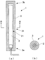
以下、本発明の第1実施形態について添付図面を参照して説明する。図1(a)は、本発明の第1実施形態にかかる光加熱式ヒータの概略構成断面図であり、図1(b)は、図1(a)におけるA−A断面を示す概略構成断面図である。この第1実施形態に係る光加熱式ヒータ1は、加熱される被加熱流体である液体中に投入されて使用される投げ込みタイプのヒータであり、図1(a)や図1(b)に示すように、ハロゲンランプ2と、当該ハロゲンランプ2を密閉して囲繞するケーシング3とを備えて構成されている。   Hereinafter, a first embodiment of the present invention will be described with reference to the accompanying drawings. FIG. 1A is a schematic configuration sectional view of an optical heating type heater according to a first embodiment of the present invention, and FIG. 1B is a schematic configuration sectional view showing an AA section in FIG. FIG. The light heating type heater 1 according to the first embodiment is a throw-in type heater which is used by being introduced into a liquid which is a fluid to be heated, and is shown in FIGS. 1A and 1B. As shown in FIG. 1, it is configured to include a halogen lamp 2 and a casing 3 that hermetically surrounds the halogen lamp 2.

ハロゲンランプ2は、加熱源であり、例えば、一定面積を短時間で加熱可能な平行光型ハロゲンランプ2、局所的な加熱が可能な集光型ハロゲン型ランプ等を使用することができる。本実施形態においては、ハロゲンランプ2として、光を照射する照射部21形状が長尺状の棒状形態の平行光型ハロゲンランプ2を採用している。ハロゲンランプ2は、図示しない制御装置に接続されており、ケーシング3内、或いは、ケーシング3の外表面上に設置される熱電対等の温度センサー(図示せず)の計測温度に基づいて、その熱出力をコントロールできるように構成されている。熱出力のコントロール方式は、自動制御であってもよく、或いは、人が操作するマニュアル制御であってもよい。   The halogen lamp 2 is a heating source, and for example, a parallel light type halogen lamp 2 capable of heating a fixed area in a short time, a condensing type halogen lamp capable of locally heating, or the like can be used. In the present embodiment, as the halogen lamp 2, a parallel light type halogen lamp 2 having a long rod-shaped irradiation unit 21 for irradiating light is used. The halogen lamp 2 is connected to a control device (not shown), and based on a temperature measured by a temperature sensor (not shown) such as a thermocouple installed in the casing 3 or on the outer surface of the casing 3, the heat of the halogen lamp 2 is measured. It is configured to control the output. The control method of heat output may be automatic control or manual control operated by a person.

また、図1(a)や図1(b)においては、光加熱式ヒータ1が、単一のハロゲンランプ2を備えるように構成されているが、数本のハロゲンランプ2を備えるように構成してもよい。複数のハロゲンランプ2を備えるような場合、各ランプの熱出力を独立的に制御してもよく、或いは、全てのランプを一つの制御単位として、熱出力を制御してもよい。   1 (a) and 1 (b), the light heating type heater 1 is configured to include a single halogen lamp 2, but is configured to include several halogen lamps 2. May be. When a plurality of halogen lamps 2 are provided, the heat output of each lamp may be controlled independently, or the heat output may be controlled using all the lamps as one control unit.

ケーシング3は、ハロゲンランプ2をその内部に収納する部材であり、加熱対象である被加熱流体が直接ハロゲンランプ2に接触しないように、該ハロゲンランプ2を密閉して囲繞する部材である。このケーシング3は、一方端側3a及び他方端側3bが閉塞される筒状に形成されている。筒状のケーシング3の一方端側3aには、ハロゲンランプ2の一方端が固定されており、ケーシング3の内周面と、ハロゲンランプ2の照射部21の表面との間に所定の間隔を設け、照射部21が、ケーシング3の内周面と接触しないように構成されている。なお、ハロゲンランプ2の一方端が固定されるケーシング3の一方端3aには、貫通孔が形成されており、該貫通孔を介してハロゲンランプ2の電源配線や制御配線がケーシング3の外部に引き出される構造を有している。なお、この貫通孔は、耐熱性の樹脂材料で密封され、また、引き出された配線類も耐熱性の樹脂材料等で被覆されている。このような樹脂材料としては、後述のケーシング3を形成する樹脂材料を用いることができる。   The casing 3 is a member that accommodates the halogen lamp 2 therein, and is a member that hermetically surrounds the halogen lamp 2 so that the fluid to be heated as a heating target does not directly contact the halogen lamp 2. The casing 3 is formed in a tubular shape in which one end 3a and the other end 3b are closed. One end of the halogen lamp 2 is fixed to one end 3 a of the cylindrical casing 3, and a predetermined distance is provided between the inner peripheral surface of the casing 3 and the surface of the irradiation unit 21 of the halogen lamp 2. The irradiation unit 21 is provided so as not to contact the inner peripheral surface of the casing 3. A through hole is formed in one end 3a of the casing 3 to which one end of the halogen lamp 2 is fixed, and power supply wiring and control wiring of the halogen lamp 2 are connected to the outside of the casing 3 through the through hole. It has a structure to be pulled out. The through holes are sealed with a heat-resistant resin material, and the drawn-out wirings are also covered with a heat-resistant resin material. As such a resin material, a resin material forming the casing 3 described later can be used.

このケーシング3は、フッ素系樹脂から形成されている。フッ素系樹脂としては、例えば、ポリテトラフルオロエチレン(PTFE)、テトラフルオロエチレン−パーフルオロアルキルビニルエーテル共重合体(PFA)、テトラフルオロエチレン−ヘキサフルオロプロピレン共重合体(FEP)、エチレン−テトラフルオロエチレン共重合体(ETFE)、ポリフッ化ビニリデン(PVDF)、ポリクロロトリフルオロエチレン(PCTFE)、テトラフルオロエチレン−ヘキサフルオロプロピレン−パーフルオロアルキルビニルエーテル共重合体(EPE)等を挙げることができる。本実施形態においては、上記各フッ素系樹脂材料の中で特に耐熱性が高いリテトラフルオロエチレン(PTFE;融点330℃)を用いてケーシング3を構成している。   This casing 3 is formed from a fluororesin. Examples of the fluorine-based resin include polytetrafluoroethylene (PTFE), tetrafluoroethylene-perfluoroalkylvinyl ether copolymer (PFA), tetrafluoroethylene-hexafluoropropylene copolymer (FEP), ethylene-tetrafluoroethylene Copolymer (ETFE), polyvinylidene fluoride (PVDF), polychlorotrifluoroethylene (PCTFE), tetrafluoroethylene-hexafluoropropylene-perfluoroalkylvinyl ether copolymer (EPE), and the like can be given. In the present embodiment, the casing 3 is formed by using, among the above-mentioned fluorine-based resin materials, particularly tetralithoethylene (PTFE; melting point: 330 ° C.) having high heat resistance.

また、ケーシング3の筒状部分は、ハロゲンランプ2の光を外部に透過させる透過部31を構成している。   Further, the cylindrical portion of the casing 3 constitutes a transmission section 31 for transmitting the light of the halogen lamp 2 to the outside.

このような構成の光加熱式ヒータ1は、例えば、加熱対象である液体(被加熱流体)が貯留された貯留槽中に投げ入れられて使用される。ハロゲンランプ2から照射された光は、ケーシング3におけるフッ素系樹脂製の透過部31にほとんど吸収されることなく透過して液体(被加熱流体)を直接加熱する。なお、ケーシング3は、フッ素系樹脂材料から形成されているため、その耐熱温度は、約200℃〜300℃程度である一方、ハロゲンランプ2の表面温度が、例えば、600℃〜800℃程度の温度に達することになるが、加熱されている液体(被加熱流体)中に光加熱式ヒータ1を浸漬している間は、ケーシング3の表面に接している液体(被加熱流体)がケーシング3の熱を強力に持ち去ってくれるため、ケーシング3の温度が耐熱温度を超えて溶融するような事態が発生することは無い。   The light heating type heater 1 having such a configuration is used, for example, by being thrown into a storage tank in which a liquid to be heated (a fluid to be heated) is stored. The light emitted from the halogen lamp 2 is transmitted through the fluororesin transmitting portion 31 of the casing 3 without being absorbed, and directly heats the liquid (fluid to be heated). Since the casing 3 is formed of a fluorine-based resin material, its heat-resistant temperature is about 200 ° C. to 300 ° C., while the surface temperature of the halogen lamp 2 is, for example, about 600 ° C. to 800 ° C. Although the temperature reaches the temperature, while the light heater 1 is immersed in the liquid being heated (fluid to be heated), the liquid (fluid to be heated) in contact with the surface of the casing 3 is Since the heat of the casing 3 is strongly removed, there is no possibility that the temperature of the casing 3 exceeds the heat-resistant temperature and is melted.

本発明に係る第1実施形態の光加熱式ヒータ1は、上述のようにハロゲンランプ2から照射される光によって直接的に液体(被加熱流体)を加熱するものであることから、高い加熱効率・加熱能力を有するものでありながら、ケーシング3をフッ素系樹脂から形成しているため、フッ化水素酸やリン酸、強アルカリ等といった液体によって該ケーシング3が腐食されることなく、これら液体を加熱することが可能となる。また、超純水を加熱する場合、従来の石英管をケーシングとして備えるヒータの場合、石英管(石英ガラス)の成分溶出が問題になるが、本発明に係る光加熱式ヒータ1の場合には、石英ガラスの成分溶出の問題が発生することがないため、超純水の加熱にも適するものとなる。また、フッ素樹脂系のケーシング3を備えているため、外部からの衝撃にも強く、光加熱式ヒータ1が破損してしまうことを効果的に抑制することもできる。   The light heating type heater 1 according to the first embodiment of the present invention directly heats a liquid (fluid to be heated) by the light emitted from the halogen lamp 2 as described above, and thus has a high heating efficiency. -Since the casing 3 is made of a fluorine-based resin while having a heating ability, the casing 3 is not corroded by a liquid such as hydrofluoric acid, phosphoric acid, or a strong alkali, and these liquids are used. It becomes possible to heat. Further, when heating ultrapure water, in the case of a heater provided with a conventional quartz tube as a casing, elution of components in the quartz tube (quartz glass) becomes a problem, but in the case of the light heater 1 according to the present invention, Since the problem of elution of the components of quartz glass does not occur, it is suitable for heating ultrapure water. In addition, since the casing 3 is made of a fluorine resin, the casing 3 is resistant to external impacts and can effectively prevent the light heater 1 from being damaged.

以上、本発明の第1実施形態に係る光加熱式ヒータ1について説明したが、光加熱式ヒータ1の具体的構成は、上記実施形態に限定されない。例えば、図2(a)の概略構成断面図や、そのB−B断面を示す概略構成断面図である図2(b)に示すように、ケーシング3とハロゲンランプ2との間に配置される石英管5を備えるように構成してもよい。この石英管5は、光透過性及び耐熱性に優れた管状体であり、少なくともハロゲンランプ2の筒状部分(照射部21)に対応した位置(対向する位置)に配設されている。また、石英管5の一方端は、ケーシング3の一方端3aに接続固定されてケーシング3内部に収納されている。また、石英管5は、少なくともケーシング3における透過部31に、密接して配置されることが好ましい。   As described above, the light heating type heater 1 according to the first embodiment of the present invention has been described, but the specific configuration of the light heating type heater 1 is not limited to the above embodiment. For example, as shown in the schematic cross-sectional view of FIG. 2A and the schematic cross-sectional view of FIG. You may comprise so that the quartz tube 5 may be provided. The quartz tube 5 is a tubular body having excellent light transmittance and heat resistance, and is disposed at least at a position (opposing position) corresponding to the cylindrical portion (irradiation portion 21) of the halogen lamp 2. One end of the quartz tube 5 is connected and fixed to one end 3 a of the casing 3 and housed inside the casing 3. In addition, it is preferable that the quartz tube 5 is arranged closely to at least the transmission part 31 of the casing 3.

ここで、本発明に係る光加熱式ヒータ1のケーシング3は、フッ素系樹脂材料から形成されているため、その温度が上昇していくと軟化して変形しやすい状態になってしまう。このような状態で、加熱対象の液体(被加熱流体)の液圧がケーシング3に加わると該ケーシング3の一部が内側に変形してハロゲンランプ2に近づくおそれがあり、仮に、ケーシング3の変形が大きくなり、ケーシング3の変形個所がハロゲンランプ2の照射部21の表面に接触した場合、ケーシング3に破れ等の損傷が発生するおそれがある。しかしながら、上記石英管5をケーシング3の内面とハロゲンランプ2の照射部21との間に配置することにより、ケーシング3の一部がハロゲンランプ2の照射部21に近づくような変形が発生したとしても、当該石英管5が、ケーシング3を支えてその変形を抑制させるストッパとしての機能を発揮し、ケーシング3の変形個所がハロゲンランプ2の照射部21の表面に接触してしまうような事態が発生することを効果的に抑制して、ケーシング3に破れ等の損傷が発生することを防止することができる。   Here, since the casing 3 of the light heating type heater 1 according to the present invention is formed of a fluorine-based resin material, as the temperature increases, the casing 3 is softened and easily deformed. In such a state, when the liquid pressure of the liquid to be heated (the fluid to be heated) is applied to the casing 3, a part of the casing 3 may be deformed inward and approach the halogen lamp 2. If the deformation becomes large and the deformed portion of the casing 3 comes into contact with the surface of the irradiation part 21 of the halogen lamp 2, the casing 3 may be damaged or damaged. However, by disposing the quartz tube 5 between the inner surface of the casing 3 and the irradiation part 21 of the halogen lamp 2, it is assumed that a deformation such that a part of the casing 3 approaches the irradiation part 21 of the halogen lamp 2 occurs. In this case, the quartz tube 5 functions as a stopper that supports the casing 3 and suppresses the deformation, and the deformed portion of the casing 3 may come into contact with the surface of the irradiation unit 21 of the halogen lamp 2. It is possible to effectively suppress the occurrence of the damage and prevent the casing 3 from being damaged or damaged.

特に、少なくともケーシング3における透過部31に対して石英管5を密接して配置するような構成を採用する場合には、ケーシング3の軟化に伴う変形自体を防止することが可能となる。   In particular, when a configuration is adopted in which the quartz tube 5 is arranged so as to be in close contact with at least the transmission part 31 in the casing 3, it is possible to prevent the deformation itself associated with the softening of the casing 3.

また、上記第1実施形態においては、ケーシング3全体をフッ素系樹脂から形成するように構成しているが、このような構成に特に限定されず、少なくともハロゲンランプ2から照射される光を外部に透過させる透過部31をフッ素系樹脂により構成し、この透過部31以外の部分については、フッ化水素酸やリン酸、強アルカリといった液体に対して耐食性を有するフッ素系樹脂以外の材料により構成してもよい。   Further, in the first embodiment, the entire casing 3 is formed from a fluororesin. However, the present invention is not particularly limited to such a configuration. The transmitting portion 31 to be transmitted is made of a fluororesin, and the portion other than the transmitting portion 31 is made of a material other than the fluororesin having corrosion resistance to liquids such as hydrofluoric acid, phosphoric acid, and strong alkali. You may.

また、上記第1実施形態においては、ハロゲンランプ2の熱出力を制御する装置や、温度センサーを備えるように構成されているが、これら制御装置や温度センサーを省略して光加熱式ヒータ1を構成してもよい。このような構成を採用する場合、加熱される液体(被加熱流体)の温度を計測し、光加熱式ヒータ1のON/OFF操作を行えばよい。   Further, in the first embodiment, the apparatus is configured to include the device for controlling the heat output of the halogen lamp 2 and the temperature sensor. However, the control device and the temperature sensor are omitted, and the light heating type heater 1 is omitted. You may comprise. When such a configuration is adopted, the temperature of the liquid to be heated (the fluid to be heated) may be measured, and the ON / OFF operation of the light heater 1 may be performed.

次に、本発明の第2実施形態について添付図面を参照して説明する。図3は、本発明の第2実施形態にかかる光加熱式ヒータ1の概略構成断面図であり、図4は、図3におけるC−C断面を示す概略構成断面図である。この第2実施形態に係る光加熱式ヒータ1は、上記投げ込みタイプの第1実施形態に係るヒータとは異なり、内部に液体(被加熱流体)を通過させて加熱する内部通過加熱タイプのヒータであり、図3や図4に示すように、ハロゲンランプ2と、当該ハロゲンランプ2を内部に収納するケーシング3と、該ケーシング3を更に囲繞する外部ケーシング6とを備えて構成されている。   Next, a second embodiment of the present invention will be described with reference to the accompanying drawings. FIG. 3 is a schematic configuration cross-sectional view of a light heating type heater 1 according to a second embodiment of the present invention, and FIG. 4 is a schematic configuration cross-sectional view showing a CC section in FIG. The light heating type heater 1 according to the second embodiment is different from the throw-in type heater according to the first embodiment in that it is an internal passage heating type heater in which a liquid (a fluid to be heated) is passed and heated. In addition, as shown in FIGS. 3 and 4, it is configured to include a halogen lamp 2, a casing 3 for housing the halogen lamp 2 therein, and an outer casing 6 further surrounding the casing 3.

ハロゲンランプ2の構成については、上記第1実施形態におけるものと略同一であるため、ここでは詳細な説明を省略する。   Since the configuration of the halogen lamp 2 is substantially the same as that in the first embodiment, a detailed description is omitted here.

ケーシング3は、ハロゲンランプ2をその内部に収納する部材であり、筒状に形成されている。筒状のケーシング3の一方端側3aには、ハロゲンランプ2の一方端が固定されており、筒状のケーシング3の他方端側3bには、ハロゲンランプ2の他方端が固定されている。なお、ハロゲンランプ2の一方端側及び他方端側を除いた中央部分が、照射部21を構成している。また、ケーシング3の内周面と、ハロゲンランプ2の照射部21の表面との間には所定の間隔が設けられており、照射部21が、ケーシング3内周面と接触しないように構成されている。なお、ハロゲンランプ2に接続される電源配線や制御配線は、外部ケーシング6を介して外側に引き出される構造を有している。   The casing 3 is a member that houses the halogen lamp 2 therein, and is formed in a tubular shape. One end of the halogen lamp 2 is fixed to one end 3a of the cylindrical casing 3, and the other end of the halogen lamp 2 is fixed to the other end 3b of the cylindrical casing 3. The central portion of the halogen lamp 2 excluding one end and the other end constitutes the irradiation unit 21. In addition, a predetermined interval is provided between the inner peripheral surface of the casing 3 and the surface of the irradiation unit 21 of the halogen lamp 2, and the irradiation unit 21 is configured so as not to contact the inner peripheral surface of the casing 3. ing. The power supply wiring and the control wiring connected to the halogen lamp 2 have a structure that is drawn out through the outer casing 6.

このケーシング3は、フッ素系樹脂から形成されている。フッ素系樹脂としては、例えば、ポリテトラフルオロエチレン(PTFE)、テトラフルオロエチレン−パーフルオロアルキルビニルエーテル共重合体(PFA)、テトラフルオロエチレン−ヘキサフルオロプロピレン共重合体(FEP)、エチレン−テトラフルオロエチレン共重合体(ETFE)、ポリフッ化ビニリデン(PVDF)、ポリクロロトリフルオロエチレン(PCTFE)、テトラフルオロエチレン−ヘキサフルオロプロピレン−パーフルオロアルキルビニルエーテル共重合体(EPE)等を挙げることができる。本実施形態においては、上記各フッ素系樹脂材料の中で特に耐熱性が高いリテトラフルオロエチレン(PTFE;融点330℃)を用いてケーシング3を構成している。   This casing 3 is formed from a fluororesin. Examples of the fluorine-based resin include polytetrafluoroethylene (PTFE), tetrafluoroethylene-perfluoroalkylvinyl ether copolymer (PFA), tetrafluoroethylene-hexafluoropropylene copolymer (FEP), ethylene-tetrafluoroethylene Copolymer (ETFE), polyvinylidene fluoride (PVDF), polychlorotrifluoroethylene (PCTFE), tetrafluoroethylene-hexafluoropropylene-perfluoroalkylvinyl ether copolymer (EPE), and the like can be given. In the present embodiment, the casing 3 is formed by using, among the above-mentioned fluorine-based resin materials, particularly tetralithoethylene (PTFE; melting point: 330 ° C.) having high heat resistance.

また、この第2実施形態に係るケーシング3は、図3や図4に示すように、その筒状部分が、内管32と、内管32との間に空間部4を形成した状態で配置される外管33とを備える二重管構造部を有するように構成されている。内管32及び外管33共に、断面視円形状に形成されている。内管32と外管33との間に形成される空間部4は、密閉空間として形成されるため、内管32の一方端と外管33の一方端とは接続して構成されており、同様に、内管32の他方端と外管33の他方端とは接続して構成されている。ケーシング3の一方端側3aには、空間部4に液体(被加熱流体)が流入可能な入口部35が設けられており、他方端側3bには、入口部35を介して内管32及び外管33の間の空間部4に流入した液体(被加熱流体)が流出可能な出口部36が設けられている。なお、フッ素系樹脂により形成される内管32が、ケーシング3における透過部31を構成する。   As shown in FIGS. 3 and 4, the casing 3 according to the second embodiment is arranged in a state where the tubular portion has a space 4 formed between the inner pipes 32. The outer tube 33 is provided with a double tube structure. Both the inner tube 32 and the outer tube 33 are formed in a circular shape in cross section. Since the space 4 formed between the inner tube 32 and the outer tube 33 is formed as a closed space, one end of the inner tube 32 and one end of the outer tube 33 are connected to each other. Similarly, the other end of the inner tube 32 and the other end of the outer tube 33 are connected to each other. At one end 3a of the casing 3, an inlet 35 through which a liquid (fluid to be heated) can flow into the space 4 is provided, and at the other end 3b, the inner pipe 32 and the An outlet 36 from which the liquid (the fluid to be heated) flowing into the space 4 between the outer tubes 33 can flow out is provided. In addition, the inner tube 32 formed of the fluororesin constitutes the transmission part 31 in the casing 3.

外部ケーシング6は、図3及び図4に示すように、内部空間を有する直方体状の筐体である。この外部ケーシング6の内部に、ハロゲンランプ2を収納したケーシング3が配置されている。この外部ケーシング6を構成する材料は特に限定されないが、上述のケーシング3と同様にフッ素系樹脂から形成されることが好ましい。外部ケーシング6の天井部には、インレット用貫通孔61と、アウトレット用貫通孔62が形成されており、インレット用貫通孔61を介して、ケーシング3における入口部35に接続される液体供給配管71が接続されており、アウトレット用貫通孔62を介して、ケーシング3における出口部36に接続される液体排出配管72が接続されている。また、外部ケーシング6の天井部には、配線用貫通孔63も形成されており、ハロゲンランプ2に接続される電源配線や制御配線や、ケーシング3の表面等に配設される温度センサーの配線等を外部ケーシング6の外に引き出されるように構成されている。   The outer casing 6 is a rectangular parallelepiped casing having an internal space, as shown in FIGS. Inside the outer casing 6, the casing 3 containing the halogen lamp 2 is arranged. The material constituting the outer casing 6 is not particularly limited, but is preferably formed of a fluorine-based resin as in the case 3 described above. A through hole 61 for an inlet and a through hole 62 for an outlet are formed in the ceiling of the outer casing 6, and a liquid supply pipe 71 connected to the inlet 35 of the casing 3 via the through hole 61 for the inlet. And a liquid discharge pipe 72 connected to the outlet 36 of the casing 3 via an outlet through-hole 62. A wiring through-hole 63 is also formed in the ceiling of the outer casing 6, and a power supply wiring and a control wiring connected to the halogen lamp 2, and a wiring of a temperature sensor disposed on the surface of the casing 3 and the like. And the like are drawn out of the outer casing 6.

ここで、図3のD−D断面を示す概略構成断面図である図5に示すように、液体供給配管71は、外部ケーシング6の天井部に対して垂直となるように配置されており、同様に、液体排出配管72も外部ケーシング6の天井部に対して垂直となるように配置されている。また、液体供給配管71が接続されるケーシング3における入口部35と、液体排出配管72が接続されるケーシング3における出口部36とは、ケーシング3の長手方向に沿う同一軸線上(図5において、紙面に対して垂直な同一の軸線上)に設けないようにして構成されている。   Here, as shown in FIG. 5, which is a schematic configuration sectional view showing a DD section of FIG. 3, the liquid supply pipe 71 is disposed so as to be perpendicular to the ceiling of the outer casing 6. Similarly, the liquid discharge pipe 72 is also arranged to be perpendicular to the ceiling of the outer casing 6. In addition, the inlet 35 in the casing 3 to which the liquid supply pipe 71 is connected and the outlet 36 in the casing 3 to which the liquid discharge pipe 72 is connected are on the same axis along the longitudinal direction of the casing 3 (in FIG. 5, (On the same axis perpendicular to the plane of the drawing).

このような構成の光加熱式ヒータ1は、液体供給配管71を通過して供給される加熱対象である液体(被加熱流体)が、ケーシング3における入口部35を介して、内管32と外管33との間の空間部4に供給される。入口部35に導かれた液体(被加熱流体)は、出口部36に向けて空間部4内を通過し、このときに、ハロゲンランプ2から照射される光によって加熱されることになる。ハロゲンランプ2から照射された光は、フッ素系樹脂製の内管32(透過部31)にほとんど吸収されることなく透過して空間部4内を通過する液体(被加熱流体)を直接加熱する。ハロゲンランプ2によって加熱された液体(被加熱流体)はケーシング3の出口部36を介して液体排出配管72に導かれ、光加熱式ヒータ1の外部に供給される。なお、ケーシング3は、フッ素系樹脂材料から形成されているため、その耐熱温度は、約200℃〜300℃程度である一方、ハロゲンランプ2の表面温度が、例えば、600℃〜800℃程度の温度に達することになるが、内管32と外管33の間に形成される空間部4内を液体(被加熱流体)が通過している間は、内管32の表面に接して流れる液体(被加熱流体)が内管32(外管33)の熱を強力に持ち去ってくれるため、ケーシング3(内管32及び外管33)の温度が耐熱温度を超えて溶融するような事態が発生することは無い。   In the light heating type heater 1 having such a configuration, the liquid to be heated (the fluid to be heated) supplied through the liquid supply pipe 71 is connected to the inner pipe 32 and the outer pipe via the inlet 35 in the casing 3. It is supplied to the space 4 between the pipe 33. The liquid (the fluid to be heated) guided to the inlet 35 passes through the space 4 toward the outlet 36, and is heated by the light emitted from the halogen lamp 2 at this time. The light emitted from the halogen lamp 2 transmits through the inner tube 32 (transmitting portion 31) made of a fluorine-based resin without being absorbed, and directly heats the liquid (the fluid to be heated) passing through the space portion 4. . The liquid (fluid to be heated) heated by the halogen lamp 2 is guided to the liquid discharge pipe 72 via the outlet 36 of the casing 3 and supplied to the outside of the light heater 1. Since the casing 3 is formed of a fluorine-based resin material, its heat-resistant temperature is about 200 ° C. to 300 ° C., while the surface temperature of the halogen lamp 2 is, for example, about 600 ° C. to 800 ° C. Although the temperature will be reached, the liquid flowing in contact with the surface of the inner tube 32 while the liquid (the fluid to be heated) passes through the space 4 formed between the inner tube 32 and the outer tube 33 Since the (heated fluid) strongly removes the heat of the inner tube 32 (outer tube 33), a situation occurs in which the temperature of the casing 3 (inner tube 32 and outer tube 33) exceeds the heat-resistant temperature and melts. Nothing to do.

本発明に係る第2実施形態の光加熱式ヒータ1は、上述のようにハロゲンランプ2から照射される光によって直接的に液体(被加熱流体)を加熱するものであることから、高い加熱効率・加熱能力を有するものでありながら、ケーシング3をフッ素系樹脂から形成しているため、フッ化水素酸やリン酸、強アルカリ等といった液体によって該ケーシング3が腐食されることなく、これら液体を加熱することが可能となる。   The light heating type heater 1 according to the second embodiment of the present invention directly heats a liquid (fluid to be heated) by the light emitted from the halogen lamp 2 as described above, and thus has a high heating efficiency. -Since the casing 3 is made of a fluorine-based resin while having a heating ability, the casing 3 is not corroded by a liquid such as hydrofluoric acid, phosphoric acid, or a strong alkali, and these liquids are used. It becomes possible to heat.

また、図5に示すように、液体供給配管71が接続されるケーシング3における入口部35と、液体排出配管72が接続されるケーシング3における出口部36とが、ケーシング3の長手方向に沿う同一軸線上に設けないようにして構成することにより、入口部35から流入した液体(被加熱流体)の空間部4内でのミキシング効果が高まり、ハロゲンランプ2からの光照射によって、より効率良く、かつ、均一に、液体(被加熱流体)を加熱することが可能となる。   As shown in FIG. 5, the inlet 35 in the casing 3 to which the liquid supply pipe 71 is connected and the outlet 36 in the casing 3 to which the liquid discharge pipe 72 is connected are the same along the longitudinal direction of the casing 3. When the liquid is not provided on the axis, the mixing effect of the liquid (fluid to be heated) flowing from the inlet 35 in the space 4 is enhanced, and the light irradiation from the halogen lamp 2 makes it more efficient. In addition, the liquid (the fluid to be heated) can be uniformly heated.

以上、本発明の第2実施形態に係る光加熱式ヒータ1について説明したが、光加熱式ヒータ1の具体的構成は、上記実施形態に限定されない。例えば、図6の概略構成断面図や、そのE−E断面を示す概略構成断面図である図7に示すように、ケーシング3が有する内管32とハロゲンランプ2との間に配置される石英管5を備えるように構成してもよい。この石英管5は、光透過性及び耐熱性に優れた管状体であり、少なくともハロゲンランプ2の筒状部分(照射部21)に対応した位置(対向する位置)に配設されている。また、石英管5は、少なくともケーシング3における内管32(透過部31)に密接して配置されることが好ましい。   As described above, the light heating type heater 1 according to the second embodiment of the present invention has been described, but the specific configuration of the light heating type heater 1 is not limited to the above embodiment. For example, as shown in the schematic cross-sectional view of FIG. 6 and the schematic cross-sectional view of the EE cross-section shown in FIG. 7, quartz disposed between the inner tube 32 of the casing 3 and the halogen lamp 2. You may comprise so that the pipe | tube 5 may be provided. The quartz tube 5 is a tubular body having excellent light transmittance and heat resistance, and is disposed at least at a position (opposing position) corresponding to the cylindrical portion (irradiation portion 21) of the halogen lamp 2. In addition, it is preferable that the quartz tube 5 is arranged at least in close contact with the inner tube 32 (the transmission part 31) in the casing 3.

ここで、第2実施形態に係る光加熱式ヒータ1のケーシング3は、フッ素系樹脂材料から形成されているため、その温度が上昇していくと軟化して変形しやすい状態になってしまう。このような状態では、内管32と外管33との間を流通する液体(被加熱流体)の液圧によって、ケーシング3の内管32の一部が変形してハロゲンランプ2に近づくおそれがあり、仮に、内管32の変形が大きくなり、内管32の変形個所がハロゲンランプ2の照射部21の表面に接触した場合、内管32に破れ等の損傷が発生するおそれがある。しかしながら、上記石英管5を内管32の内面とハロゲンランプ2の照射部21との間に配置することにより、内管32の一部がハロゲンランプ2の照射部21に近づくような変形が発生したとしても、当該石英管5が、内管32を支えてその変形を抑制させるストッパとしての機能を発揮し、内管32の変形個所がハロゲンランプ2の照射部21の表面に接触してしまうような事態が発生することを効果的に抑制して、内管32(ケーシング3)に破れ等の損傷が発生することを防止することができる。   Here, since the casing 3 of the light heating type heater 1 according to the second embodiment is formed of a fluorine-based resin material, as the temperature increases, the casing 3 is softened and easily deformed. In such a state, a part of the inner tube 32 of the casing 3 may be deformed and approach the halogen lamp 2 due to the liquid pressure of the liquid (fluid to be heated) flowing between the inner tube 32 and the outer tube 33. If the deformation of the inner tube 32 becomes large and the deformed portion of the inner tube 32 comes into contact with the surface of the irradiation part 21 of the halogen lamp 2, there is a possibility that the inner tube 32 may be broken or otherwise damaged. However, by disposing the quartz tube 5 between the inner surface of the inner tube 32 and the irradiation part 21 of the halogen lamp 2, deformation such that a part of the inner tube 32 approaches the irradiation part 21 of the halogen lamp 2 occurs. Even if it does, the quartz tube 5 functions as a stopper that supports the inner tube 32 and suppresses its deformation, and the deformed portion of the inner tube 32 comes into contact with the surface of the irradiation unit 21 of the halogen lamp 2. It is possible to effectively prevent such a situation from occurring, and prevent the inner tube 32 (casing 3) from being damaged or damaged.

特に、ケーシング3における内管32(透過部31)に対して石英管5を密接して配置するような構成を採用する場合には、ケーシング3の軟化に伴う変形自体を防止することが可能となる。   In particular, when a configuration is adopted in which the quartz tube 5 is arranged closely to the inner tube 32 (transmission part 31) in the casing 3, it is possible to prevent the deformation itself due to the softening of the casing 3. Become.

また、図8の概略構成断面図に示すように、内管32と外管33との間を接続する壁部37を空間部4内に備え、当該壁部37を、内管32の表面を螺旋状に巻回するように配置して、入口部35から出口部36に向けて伸びる螺旋状流路38を当該壁部37によって画定するように構成してもよい。このような構成を採用する場合、ケーシング3の入口部35から流入した液体(被加熱流体)は、ハロゲンランプ2の長尺状の照射部21の周りを、当該照射部21の長手方向に沿って螺旋状に回りながら出口部36へと導かれることになる為、空間部4内を通過する液体の移動距離を長くすることができ、液体(被加熱流体)がハロゲンランプ2から吸収する熱量を効果的に増加させ、より一層、効率良く液体(被加熱流体)を加熱することが可能となる。   As shown in the schematic cross-sectional view of FIG. 8, a wall portion 37 connecting the inner tube 32 and the outer tube 33 is provided in the space portion 4, and the wall portion 37 is provided on the surface of the inner tube 32. It may be arranged so as to be wound in a spiral shape, and a spiral flow path 38 extending from the inlet 35 to the outlet 36 may be defined by the wall 37. When such a configuration is adopted, the liquid (fluid to be heated) flowing from the inlet 35 of the casing 3 flows around the elongated irradiation unit 21 of the halogen lamp 2 along the longitudinal direction of the irradiation unit 21. The liquid (heated fluid) absorbs from the halogen lamp 2 because the liquid (heated fluid) absorbs the liquid (heated fluid) from the halogen lamp 2 because it is guided to the outlet 36 while spirally rotating. And the liquid (the fluid to be heated) can be more efficiently heated.

また、第2実施形態に係る光加熱式ヒータ1は、外部ケーシング6を備える構成であるが、このような外部ケーシング6を省略して、内部通過加熱タイプのヒータとして光加熱式ヒータ1を構成してもよい。   In addition, the light heating type heater 1 according to the second embodiment is configured to include the outer casing 6, but such an outer casing 6 is omitted, and the light heating type heater 1 is configured as an internal passage heating type heater. May be.

また、第2実施形態に係る光加熱式ヒータ1において、アルミ箔や金箔等の金属シートによって外部ケーシングの周囲を被覆するように構成してもよい。このような金属シートの被覆を行うことにより、より一層、液体(被加熱流体)に対する加熱効率を向上させることができる。また、ハロゲンランプから照射される光の約10%〜20%が、外部ケーシングを透過して外部に逃げるが、上記金属シートを被覆することにより、外部ケーシングを透過する光による眩しさから作業者の眼を保護することができる。   Further, in the light heater 1 according to the second embodiment, the outer casing may be configured to be covered with a metal sheet such as an aluminum foil or a gold foil. By performing such coating of the metal sheet, the heating efficiency with respect to the liquid (the fluid to be heated) can be further improved. Further, about 10% to 20% of the light emitted from the halogen lamp passes through the outer casing and escapes to the outside. However, by covering the metal sheet, the worker is exposed to glare caused by the light transmitted through the outer casing. The eyes can be protected.

1 光加熱式ヒータ
2 ハロゲンランプ
21 照射部
3 ケーシング
3a ケーシングの一方端側
3b ケーシングの他方端側
31 透過部
32 内管
33 外管
34 空間部
35 入口部
36 出口部
37 壁部
38 螺旋状流路
4 空間部
5 石英管
6 外部ケーシング
61 インレット用貫通孔
62 アウトレット用貫通孔
63 配線用貫通孔
71 液体供給配管
72 液体排出配管
DESCRIPTION OF SYMBOLS 1 Light heating type heater 2 Halogen lamp 21 Irradiation part 3 Casing 3a One end side of casing 3b The other end side of casing 31 Transmissive part 32 Inner pipe 33 Outer pipe 34 Space 35 Inlet 36 Outlet 37 Wall 38 Spiral flow Road 4 Space portion 5 Quartz tube 6 Outer casing 61 Inlet through hole 62 Outlet through hole 63 Wiring through hole 71 Liquid supply pipe 72 Liquid discharge pipe

Claims (9)

ハロゲンランプと、前記ハロゲンランプを密閉して囲繞するケーシングとを備える光加熱式ヒータであって、
前記ケーシングは、前記ハロゲンランプの光を外部に透過させる透過部を備えており、
前記透過部は、フッ素系樹脂から形成されていることを特徴とする光加熱式ヒータ。
A light heating type heater including a halogen lamp and a casing that hermetically surrounds the halogen lamp,
The casing includes a transmission unit that transmits light of the halogen lamp to the outside,
The light-transmitting heater is characterized in that the transmission section is formed of a fluorine resin.
前記フッ素系樹脂は、ポリテトラフルオロエチレン (PTFE) であることを特徴とする請求項1に記載の光加熱式ヒータ。   The heater according to claim 1, wherein the fluorine-based resin is polytetrafluoroethylene (PTFE). 前記ケーシングと前記ハロゲンランプとの間に配置される石英管を備えることを特徴とする請求項1又は2に記載の光加熱式ヒータ。   The light heating type heater according to claim 1, further comprising a quartz tube disposed between the casing and the halogen lamp. 前記石英管は、前記ケーシングにおける前記透過部に密接して配置されることを特徴とする請求項3に記載の光加熱式ヒータ。   The light heating type heater according to claim 3, wherein the quartz tube is disposed in close contact with the transmission portion in the casing. ハロゲンランプと、前記ハロゲンランプを内部に収納する筒状ケーシングとを備える光加熱式ヒータであって、
前記ケーシングは、内管と、前記内管との間に空間部を形成した状態で配置される外管とを備える二重管構造部を有しており、
前記ケーシングの一方端側には、被加熱流体が前記空間部に流入可能な入口部が設けられており、他方端側には、前記入口部を介して前記空間部に流入した被加熱流体が流出可能な出口部が設けられており、
前記内管及び外管は、フッ素系樹脂から形成されていることを特徴とする光加熱式ヒータ。
A light heating type heater including a halogen lamp and a cylindrical casing that houses the halogen lamp therein,
The casing has a double pipe structure including an inner pipe and an outer pipe arranged in a state where a space is formed between the inner pipe and the casing,
On one end side of the casing, an inlet portion through which a heated fluid can flow into the space portion is provided, and on the other end side, a heated fluid flowing into the space portion via the inlet portion is provided. There is an outlet part that can flow out,
The inner tube and the outer tube are formed of a fluorine-based resin.
前記フッ素系樹脂は、ポリテトラフルオロエチレン (PTFE) であることを特徴とする請求項5に記載の光加熱式ヒータ。   The heater according to claim 5, wherein the fluorine-based resin is polytetrafluoroethylene (PTFE). 前記内管と前記ハロゲンランプとの間に配置される石英管を備えることを特徴とする請求項5又は6に記載の光加熱式ヒータ。   7. The heater according to claim 5, further comprising a quartz tube disposed between the inner tube and the halogen lamp. 前記石英管は、前記内管に密接して配置されることを特徴とする請求項7に記載の光加熱式ヒータ。   The light heating type heater according to claim 7, wherein the quartz tube is arranged closely to the inner tube. 前記内管と前記外管との間を接続する壁部を備えており、
前記壁部は、前記内管の表面を螺旋状に巻回するように配置され、前記入口部から前記出口部に向けて伸びる螺旋状流路を画定することを特徴とする請求項5から8のいずれかに記載の光加熱式ヒータ。


A wall portion connecting between the inner tube and the outer tube,
9. The wall according to claim 5, wherein the wall is arranged to spirally wind the surface of the inner tube, and defines a spiral flow path extending from the inlet to the outlet. 10. The light heating type heater according to any one of the above.


JP2018129688A 2018-07-09 2018-07-09 Optical heating type heater Pending JP2020009628A (en)

Priority Applications (1)

Application Number Priority Date Filing Date Title
JP2018129688A JP2020009628A (en) 2018-07-09 2018-07-09 Optical heating type heater

Applications Claiming Priority (1)

Application Number Priority Date Filing Date Title
JP2018129688A JP2020009628A (en) 2018-07-09 2018-07-09 Optical heating type heater

Publications (1)

Publication Number Publication Date
JP2020009628A true JP2020009628A (en) 2020-01-16

Family

ID=69152050

Family Applications (1)

Application Number Title Priority Date Filing Date
JP2018129688A Pending JP2020009628A (en) 2018-07-09 2018-07-09 Optical heating type heater

Country Status (1)

Country Link
JP (1) JP2020009628A (en)

Cited By (2)

* Cited by examiner, † Cited by third party
Publication number Priority date Publication date Assignee Title
JP2021115196A (en) * 2020-01-24 2021-08-10 株式会社三共 Game machine
JP2021115198A (en) * 2020-01-24 2021-08-10 株式会社三共 Game machine

Citations (6)

* Cited by examiner, † Cited by third party
Publication number Priority date Publication date Assignee Title
JPS6261286A (en) * 1985-09-12 1987-03-17 早川 哲夫 Infrared ray emitting unit used in liquid
JPH1183172A (en) * 1997-08-29 1999-03-26 Komatsu Electron Kk Fluid heater
JP2007017098A (en) * 2005-07-08 2007-01-25 Tokyo Electron Ltd Fluid heater
JP2008096057A (en) * 2006-10-13 2008-04-24 Toho Kasei Kk Liquid heating device
JP2011075145A (en) * 2009-09-29 2011-04-14 Fuji Heavy Ind Ltd Fluid heating device and circulation type heating treatment system using the same
WO2013041391A1 (en) * 2011-09-23 2013-03-28 Nestec S.A. Heater for beverage preparation machines and method for manufacturing the same

Patent Citations (6)

* Cited by examiner, † Cited by third party
Publication number Priority date Publication date Assignee Title
JPS6261286A (en) * 1985-09-12 1987-03-17 早川 哲夫 Infrared ray emitting unit used in liquid
JPH1183172A (en) * 1997-08-29 1999-03-26 Komatsu Electron Kk Fluid heater
JP2007017098A (en) * 2005-07-08 2007-01-25 Tokyo Electron Ltd Fluid heater
JP2008096057A (en) * 2006-10-13 2008-04-24 Toho Kasei Kk Liquid heating device
JP2011075145A (en) * 2009-09-29 2011-04-14 Fuji Heavy Ind Ltd Fluid heating device and circulation type heating treatment system using the same
WO2013041391A1 (en) * 2011-09-23 2013-03-28 Nestec S.A. Heater for beverage preparation machines and method for manufacturing the same

Cited By (2)

* Cited by examiner, † Cited by third party
Publication number Priority date Publication date Assignee Title
JP2021115196A (en) * 2020-01-24 2021-08-10 株式会社三共 Game machine
JP2021115198A (en) * 2020-01-24 2021-08-10 株式会社三共 Game machine

Similar Documents

Publication Publication Date Title
KR101357056B1 (en) Fluid heating device
JPH05231712A (en) Fluid heater
US9499415B2 (en) Ultraviolet irradiation apparatus
JP2020009628A (en) Optical heating type heater
JP2007017098A (en) Fluid heater
JP6244080B2 (en) UV irradiation equipment
JP2009002606A (en) Steam generator
US7015437B2 (en) Method device for heating fluids
JP2008096057A (en) Liquid heating device
JP2007101048A (en) Gas heater
JP2008202844A (en) Fluid heating device
JPH10259955A (en) Liquid temperature control device
JP2008082571A (en) Liquid heating device
JPS6365251A (en) Heating of liquid
JP3042637U (en) Liquid heating device
JP2009264646A (en) Liquid heating device
JP3043543U (en) Liquid heating device
KR101809169B1 (en) Apparatus for Heating Fluid
JP2000304353A (en) Liquid-heating device
KR20200001256A (en) Heat Exchanger and heating device having the same
JPH10281583A (en) Fluid heating or cooling apparatus
JP6417572B2 (en) Fluid heating device
JP2023135922A (en) Ultraviolet reflection layer
KR101815157B1 (en) An inline mixing and heating apparatus
JP3044232U (en) Liquid heating device

Legal Events

Date Code Title Description
A621 Written request for application examination

Free format text: JAPANESE INTERMEDIATE CODE: A621

Effective date: 20210706

A977 Report on retrieval

Free format text: JAPANESE INTERMEDIATE CODE: A971007

Effective date: 20220715

A131 Notification of reasons for refusal

Free format text: JAPANESE INTERMEDIATE CODE: A131

Effective date: 20220726

A521 Request for written amendment filed

Free format text: JAPANESE INTERMEDIATE CODE: A523

Effective date: 20220926

A131 Notification of reasons for refusal

Free format text: JAPANESE INTERMEDIATE CODE: A131

Effective date: 20230119

A521 Request for written amendment filed

Free format text: JAPANESE INTERMEDIATE CODE: A523

Effective date: 20230317

A02 Decision of refusal

Free format text: JAPANESE INTERMEDIATE CODE: A02

Effective date: 20230404