EP1741977A1 - Brûleur à charbon pulvérisé pour émissions réduites de NOx - Google Patents
Brûleur à charbon pulvérisé pour émissions réduites de NOx Download PDFInfo
- Publication number
- EP1741977A1 EP1741977A1 EP06013706A EP06013706A EP1741977A1 EP 1741977 A1 EP1741977 A1 EP 1741977A1 EP 06013706 A EP06013706 A EP 06013706A EP 06013706 A EP06013706 A EP 06013706A EP 1741977 A1 EP1741977 A1 EP 1741977A1
- Authority
- EP
- European Patent Office
- Prior art keywords
- air tube
- burner
- primary air
- mouth
- primary
- Prior art date
- Legal status (The legal status is an assumption and is not a legal conclusion. Google has not performed a legal analysis and makes no representation as to the accuracy of the status listed.)
- Granted
Links
- 239000003245 coal Substances 0.000 title claims description 34
- 230000006641 stabilisation Effects 0.000 claims abstract 2
- 238000011105 stabilization Methods 0.000 claims abstract 2
- 230000000087 stabilizing effect Effects 0.000 claims description 26
- 239000003077 lignite Substances 0.000 claims description 13
- 239000000446 fuel Substances 0.000 claims description 12
- 238000011144 upstream manufacturing Methods 0.000 claims description 5
- 238000009750 centrifugal casting Methods 0.000 claims description 4
- 238000003466 welding Methods 0.000 claims description 4
- 239000002817 coal dust Substances 0.000 abstract description 7
- 238000002485 combustion reaction Methods 0.000 description 19
- 238000006722 reduction reaction Methods 0.000 description 12
- 230000009467 reduction Effects 0.000 description 11
- MWUXSHHQAYIFBG-UHFFFAOYSA-N nitrogen oxide Inorganic materials O=[N] MWUXSHHQAYIFBG-UHFFFAOYSA-N 0.000 description 6
- 239000000428 dust Substances 0.000 description 5
- 238000000926 separation method Methods 0.000 description 5
- 239000002245 particle Substances 0.000 description 4
- IJGRMHOSHXDMSA-UHFFFAOYSA-N Atomic nitrogen Chemical compound N#N IJGRMHOSHXDMSA-UHFFFAOYSA-N 0.000 description 3
- OKTJSMMVPCPJKN-UHFFFAOYSA-N Carbon Chemical compound [C] OKTJSMMVPCPJKN-UHFFFAOYSA-N 0.000 description 3
- 229910052799 carbon Inorganic materials 0.000 description 3
- 238000006243 chemical reaction Methods 0.000 description 3
- 150000001875 compounds Chemical class 0.000 description 3
- 230000003111 delayed effect Effects 0.000 description 3
- 238000009826 distribution Methods 0.000 description 3
- 238000005516 engineering process Methods 0.000 description 3
- 239000007789 gas Substances 0.000 description 3
- 238000000034 method Methods 0.000 description 3
- 239000001301 oxygen Substances 0.000 description 3
- 229910052760 oxygen Inorganic materials 0.000 description 3
- 239000000047 product Substances 0.000 description 3
- QVGXLLKOCUKJST-UHFFFAOYSA-N atomic oxygen Chemical compound [O] QVGXLLKOCUKJST-UHFFFAOYSA-N 0.000 description 2
- 230000001747 exhibiting effect Effects 0.000 description 2
- 238000004519 manufacturing process Methods 0.000 description 2
- 239000000463 material Substances 0.000 description 2
- 230000008569 process Effects 0.000 description 2
- 230000008439 repair process Effects 0.000 description 2
- UGFAIRIUMAVXCW-UHFFFAOYSA-N Carbon monoxide Chemical compound [O+]#[C-] UGFAIRIUMAVXCW-UHFFFAOYSA-N 0.000 description 1
- 230000015572 biosynthetic process Effects 0.000 description 1
- 239000007795 chemical reaction product Substances 0.000 description 1
- 238000000354 decomposition reaction Methods 0.000 description 1
- 239000003546 flue gas Substances 0.000 description 1
- 239000003517 fume Substances 0.000 description 1
- 238000000227 grinding Methods 0.000 description 1
- 238000000265 homogenisation Methods 0.000 description 1
- 230000001771 impaired effect Effects 0.000 description 1
- 230000003993 interaction Effects 0.000 description 1
- 238000002156 mixing Methods 0.000 description 1
- 238000012544 monitoring process Methods 0.000 description 1
- 238000010943 off-gassing Methods 0.000 description 1
- 230000003647 oxidation Effects 0.000 description 1
- 238000007254 oxidation reaction Methods 0.000 description 1
- 238000000197 pyrolysis Methods 0.000 description 1
- 230000004044 response Effects 0.000 description 1
- 239000007787 solid Substances 0.000 description 1
- 230000002123 temporal effect Effects 0.000 description 1
Images
Classifications
-
- F—MECHANICAL ENGINEERING; LIGHTING; HEATING; WEAPONS; BLASTING
- F23—COMBUSTION APPARATUS; COMBUSTION PROCESSES
- F23D—BURNERS
- F23D1/00—Burners for combustion of pulverulent fuel
-
- F—MECHANICAL ENGINEERING; LIGHTING; HEATING; WEAPONS; BLASTING
- F23—COMBUSTION APPARATUS; COMBUSTION PROCESSES
- F23C—METHODS OR APPARATUS FOR COMBUSTION USING FLUID FUEL OR SOLID FUEL SUSPENDED IN A CARRIER GAS OR AIR
- F23C7/00—Combustion apparatus characterised by arrangements for air supply
- F23C7/002—Combustion apparatus characterised by arrangements for air supply the air being submitted to a rotary or spinning motion
- F23C7/004—Combustion apparatus characterised by arrangements for air supply the air being submitted to a rotary or spinning motion using vanes
- F23C7/006—Combustion apparatus characterised by arrangements for air supply the air being submitted to a rotary or spinning motion using vanes adjustable
-
- F—MECHANICAL ENGINEERING; LIGHTING; HEATING; WEAPONS; BLASTING
- F23—COMBUSTION APPARATUS; COMBUSTION PROCESSES
- F23D—BURNERS
- F23D2201/00—Burners adapted for particulate solid or pulverulent fuels
- F23D2201/10—Nozzle tips
-
- F—MECHANICAL ENGINEERING; LIGHTING; HEATING; WEAPONS; BLASTING
- F23—COMBUSTION APPARATUS; COMBUSTION PROCESSES
- F23D—BURNERS
- F23D2209/00—Safety arrangements
- F23D2209/20—Flame lift-off / stability
Definitions
- the invention is directed to a burner for burning pulverulent fuel, such as hard coal or lignite, preferably with a concentric structure comprising a primary air tube and a secondary air tube surrounding the primary air tube, wherein the mouth region of the primary air tube on the outside a Lucasabweiskhle and inside a stabilizing ring having.
- pulverulent fuel such as hard coal or lignite
- the burner technology for the combustion of dusty carbon pursues the goal at the present time of producing an intensive separation between oxygen and pyrolysis gas during the initial reaction or ignition, in order subsequently to allow the combustion air to take part in the further oxidation of the solids and thus an even more effective reduction to achieve NO x emissions.
- Such a definition can be made by the interaction of the components of a swirl generator in the primary air tube, a stabilizing ring at the mouth of the primary air tube and a Heilabweiskehle the secondary air tube, as it EP-B-670 454 describes.
- This patent discloses a generic burner, in which at the end of a burner tube, which is surrounded by a secondary air tube, arranged inside the mouth of the burner tube, a stabilizing ring and on the outside of the burner tube Lucasabweiskhle is arranged.
- the burner tube and the stabilizing ring and on the other hand the burner tube and the Heilabweiskhle must be connected to each other. This is usually done by welding, so that in this area on each side of the burner tube, a weld or a welding surface is formed. For this purpose, it is necessary that the materials are matched accordingly. The choice of materials and the formation of the weld in this area leads to increased design effort. In addition, therefore, in the high temperature loaded and flowed through by aggressive media mouth region of the primary or burner tube due to the presence of welds increased repair and susceptibility to failure and impaired by these conditions lifetime is to be expected.
- the invention is based on the object to provide a solution that makes it possible to form the mouth region of a generic burner durable and / or structurally simpler.
- this object is achieved in that the Lucasabweiskehle and the stabilizing ring are formed as a one-piece component.
- This component can then be welded, for example, by means of a circumferential weld on the end face of a burner tube or primary air tube, so that only one weld is present in the region of the mouth. Since only one weld is required, the burner can be made faster than a burner of the prior art, in which two welds are necessary. In addition, it is thereby possible, the weld with respect to the air flow in the burner or primary or secondary air tube further upstream, d. H.
- the inventively designed burner region is characterized more durable, d. H. less susceptible to interference and repair and structurally simpler.
- the centrifugal casting method for the production of the one-piece component, in particular the centrifugal casting method is suitable, so that the invention provides in an embodiment that the one-piece component is produced by centrifugal casting.
- the invention provides in an embodiment that the one-piece component to the primary air tube, preferably by welding, is fixed.
- the one-piece component can expediently also have a part which then forms an extension of the primary air tube , so to speak as part of the primary air tube is to be regarded.
- the invention is therefore further characterized in an embodiment also in that the Lucasabweiskehle, the stabilizing ring and at least a portion of the primary air tube are integrally formed, in particular form the mouth region of the primary air tube.
- a particularly expedient and advantageous development of the invention furthermore consists in that the stabilizing ring terminates with the mouth of the primary air tube and / or terminates the air deflector throat flush with the mouth of the primary air tube.
- the invention is characterized by a arranged in the annular gap between the primary air tube and the secondary air duct air guide body which is adjustable in and against the flow direction between a retracted position in the annular gap and a flush with the mouth of the primary air pipe final position.
- the burner has a core air tube arranged in the primary air tube, in which a pilot burner which is disposed between a burner ignition position and a burner operating position in and against the burner Flow direction is displaceable, is arranged, which the invention also provides.
- the mouth of the core air tube is arranged upstream of the mouth of the primary air tube.
- the invention also provides that a swirl body is arranged on the ignition-flame-side end of the pilot burner.
- a particularly advantageous embodiment of the swirl body according to the invention is characterized in that on the swirl body, a pipe section is arranged around the ZündbrennerlShsachse, the preferably conically formed ignition flame end of the pipe section in the burner ignition position of the burner via the outlet end (mouth) of the primary air pipe protrudes.
- the invention provides that a primary swirl body is arranged in the annular gap between the core air tube and the primary air tube.
- the invention is based on the known from the prior art burner technology for the combustion of pulverized hard coal and pulverized lignite.
- the burner according to the invention which can be used both for the combustion of hard coal and for the combustion of lignite, preferably has a concentric structure with a primary air tube and a secondary air tube.
- the surrounded by the cylindrical secondary air tube primary air tube forms this with a combustion air leading annular channel (secondary air channel).
- an air deflector throat is arranged on the outside at the outlet end (mouth) of the primary air tube, which narrows the cross section of the annular channel between the primary air tube and the secondary air tube at the outlet ends and preferably terminates flush with the mouth.
- a stabilizing ring On the inside at the outlet end (mouth) of the primary air tube, a stabilizing ring is arranged, which is formed by an inner edge to the burner longitudinal edge, which preferably terminates flush with the mouth and protrudes into the flow of primary air and coal dust.
- a secondary air guide is arranged, which is adjustable in the flow direction of a retracted position in the annular channel and a flush with the mouth of the primary air tube final position.
- the burner according to the invention additionally has a core air tube which is surrounded by the cylindrical primary air tube and forms a primary air and pulverized coal-carrying annular channel (primary air nozzle or dust tube nozzle). Due to the concentric arrangement of the core air tube, primary air tube and secondary air tube an individual single air supply is possible.
- a pilot burner is disposed within the core air tube in the burner longitudinal axis.
- a swirler is attached in the form of a blade ring, which is covered in the radial direction at its outer end by a pipe extension extending in Direction of flow widens conically and extends beyond the mouth of the pilot out.
- the pilot burner, the swirl body of the pilot burner and the conical tube extension are preferably designed as a one-piece component, which is displaceable in the flow direction from a retracted position in the core air tube to a position at the mouth of the core air tube.
- the mixing intensity of fuel and combustion air may be adjusted by a primary swirler disposed in the annular channel between the core air tube and the primary air tube, and a secondary swirler disposed in the annular channel between the primary air tube and the secondary air tube.
- the burner according to the invention makes possible, beyond the burner technology for pulverized coal known from the prior art, burner operation in which the reduction reactions of an oxygen-poor (substoichiometric) combustion chamber are shifted into the burner-near zone between primary flame and secondary air flow.
- an oxygen-poor flue gas recirculation zone is established in this region near the burner, in which NO compounds which inevitably form during the primary reaction are split and reduced to molecular nitrogen.
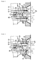
- the burner according to the invention which is shown in FIGS. 1 to 4, has a pilot burner 7 which can be displaced in the direction of flow and which is arranged in the burner longitudinal axis within a core air tube 6.
- the cylindrical core air tube 6 is surrounded by a cylindrical primary air tube 1, whereby an annular channel is formed.
- This annular channel is in turn surrounded by a cylindrical secondary air tube 2 and thereby divides the combustion air sector in at least one or two annular channels.
- the fuel and air conducting primary air ring passage formed by the core air tube 6 and the primary air tube 1 is connected to a mill, not shown, in which the coal is ground and dried during grinding with a hot, gaseous medium.
- a primary swirl body 10 is arranged on the outside of the core air tube 6, which imparts a rotation of the primary air and pulverized coal flow.
- the flow is made uniform and the pulverized coal preferably enriched on the inside of the primary air tube 1.
- a stabilizing ring 4 is arranged on the inside at the outlet end of the primary air tube 1, which has a radially inwardly directed edge. This edge, which projects into the stream of primary air and pulverized coal, ensures that the coal particles encounter resistance before they leave the primary air tube 1, are thereby delayed and are accelerated again by the gas flow in the direction of the center of the burner tube.
- the core air tube 6 which sets the primary air coal dust flow in a rotational flow.
- This ring 4 has the shape of an internal toothing and protrudes into the flow region of the pulverized coal, so that the coal particles collide against a resistance before leaving the primary tube or primary air tube 1. Due to the impact on the ring 4, the carbon particles are braked sharply.
- the outer side of the exit-side end of the primary air tube 1 has a conically radially outwardly widening section, which represents a Heilabweiskhle 3 for the outside guided past flow of secondary air, the actual throat is provided with the reference numeral 11, the Heilabweiskehle 3 total but extends on both sides of the throat 11.
- the by the Secondary air tube 2 guided secondary air flows along or over the Lucasabweiskhle 3 to the outside, away from the fuel-rich flame kernel and is sufficiently delayed supplied to the fuel products.
- the Heilabweiskhle 3 ensures an ignition that runs without affecting the secondary air and is not disturbed by air fluctuations or turbulence.
- the core air tube 6 In order to shift the particle flow of pulverized coal from the annular channel, which is formed by the core air tube 6 and the primary air tube 1, further in the direction of the burner axis and thus increase the extent of the recirculation region, the core air tube 6, viewed in the flow direction, preferably clearly before the stabilizing ring 4 of the dust tube nozzle end.
- a safe operation of the adjustable pilot burner 7, especially in combined operation with oil and coal not possible because the inwardly directed to the burner axis flow of coal dust affects the flame of the pilot burner 7 and additionally the Ignition flame monitoring is obstructed due to the darkening of the coal dust.
- the spin burner 7 attached to the swirl body 8 is in its outer region by a Pipe extension 9 covered.
- This pipe extension 9, which surrounds the blade ring of the swirl body 8, is extended downstream conically and serves as a deflector for the coal dust, which is deflected by the stabilizing ring 4 in the direction of the burner center.
- the local position of the conical tube extension 9 is adjustable in the flow direction. This ensures reliable ignition and monitorability of the pilot burner flame in all operating situations.
- the mouth of the primary air tube 1 and the burner nozzle from Heilabweiskehle 3 and stabilizing ring 4 is formed as a component and permanently connected to the dust pipe or primary air tube 1 of the burner permanently.
- a one-piece production of the Heilabweiskhle 3 and the stabilizing ring 4 is preferred.
- This one-piece component from the Lucasabweiskhle 3 and the stabilizing ring 4 is primarily, but not exclusively produced by centrifugal casting. But even the primary air tube 1 may be part of the one-piece component with a part having the Lucasabweiskhle 3 and the stabilizing ring 4.
- FIG. 1 shows a hard coal burner in which the pilot burner 7 is retracted into the core air tube 6 and the adjustable secondary air guide body 5 is arranged in the mouth of the primary air tube 1.
- the Sekundär Kunststoffleit stresses 5 this is not further downstream and closes flush with the Heilabweiskhle 3, whereby the operation of the Heilabweiskehle 3 is amplified.
- the secondary air flowing through the annular channel formed by the primary air tube 1 and the secondary air tube 2 is deflected outwardly and moves away from the flame core of the primary combustion zone in the radial direction.
- Figure 2 shows the longitudinal section through a hard coal burner according to the invention, in which the pilot burner 7 at the in FIG 1 position is arranged and the displaceable Sekundär KunststoffleitMech 5 is retracted on the outside of the primary air tube 1 in the secondary air ring channel.
- the components are arranged for an operating state of the hard coal burner, in which a less large separation layer between primary combustion and secondary air flow and thus a less large in the radial direction Rezirkulations which downstream of the mouth of the primary air tube 1 is required.
- the adjustable pilot burner 7 is in turn withdrawn into the core air tube 6 for this operating state.
- the Sekundär Kunststoffleit Congress 5 which influences the size of the Rezirkulations involvedes by its adjustable position is retracted according to the position of the pilot burner 7 in the respective annular channel. In this position, the Sekundär Kunststoffleit analyses 5 divides the air flow of the secondary air pipe 2 into two different partial flows and makes them even. As a result, the Sekundär Kunststoffleit analyses 5 ensures that the ignition process at the burner outlet is not disturbed by air fluctuations or turbulence of the secondary air and the secondary air is sufficiently delayed fed to the fuel products.
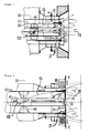
- Figure 3 shows the longitudinal section through a hard coal burner according to the invention, wherein the pilot burner 7 is arranged in the mouth of the core air tube 6 and the displaceable Sekundär Kunststoffleit analyses 5 has the position shown in Figure 1.
- the components of the burner according to the invention are arranged according to an operating state in the ignition mode or combined operation of the hard coal burner.
- the conical tube extension 9 protrudes beyond the mouth of the core air tube 6 as well as downstream beyond the stabilizing ring 4 of the primary air tube 1 in the flow direction, in order to ensure reliable ignition and monitorability of the pilot burner 7.
- the Secondary air guide 5 is, as in Figure 1, arranged in the mouth of the primary air tube 1 and downstream is not further displaced.
- the operation of the Heilabweiskhle 3 is amplified and it forms a maximum large separation layer downstream of the mouth of the primary air tube 1, in which the NO compounds of the primary reaction can be split and reduced to molecular nitrogen and an optimum in terms the NO x reduction is set for the illustrated operating state.
- FIG. 4 shows an exemplary embodiment of a lignite burner which has the same characteristics according to the invention as the hard coal burner described above. Differences to a hard coal burner exist in the proportions of the diameter of the burner pipes.
- Figure 4 shows the longitudinal section through a lignite burner according to the invention, wherein the pilot burner 7 is disposed in the mouth of the core air tube 6 and the displaceable Sekundär Kunststoffleit analyses 5 assumes a position described in FIG 3.
- the components of the burner are arranged according to an operating state in the ignition operation or combined operation of the lignite burner.
- the pilot burner 7 assumes a position in the mouth of the core air tube 6 and is not further displaced downstream.
- the conical tube extension 9 protrudes beyond the mouth of the core air tube 6 and the stabilizing ring 4, to ensure a reliable ignition of the pilot burner 7.
- the displaceable Sekundärtechnikleitoasa 5 has the position described in Figure 1 and 3, from which it is not further downstream displaced.
- the burner 5 according to the invention for the combustion of pulverized fuel such as hard coal or brown coal, a device is provided which allows a higher reduction of NO x emissions in terms of load condition and quality of the pulverized coal compared to the prior art.
Priority Applications (1)
| Application Number | Priority Date | Filing Date | Title |
|---|---|---|---|
| PL06013706T PL1741977T3 (pl) | 2005-07-07 | 2006-07-03 | Palnik na pył węglowy dla niskich emisji NOx |
Applications Claiming Priority (1)
| Application Number | Priority Date | Filing Date | Title |
|---|---|---|---|
| DE102005032109A DE102005032109B4 (de) | 2005-07-07 | 2005-07-07 | Kohlenstaubbrenner für niedrige NOx-Emissionen |
Publications (2)
| Publication Number | Publication Date |
|---|---|
| EP1741977A1 true EP1741977A1 (fr) | 2007-01-10 |
| EP1741977B1 EP1741977B1 (fr) | 2011-09-21 |
Family
ID=37054517
Family Applications (1)
| Application Number | Title | Priority Date | Filing Date |
|---|---|---|---|
| EP06013706A Active EP1741977B1 (fr) | 2005-07-07 | 2006-07-03 | Brûleur à charbon pulvérisé pour émissions réduites de NOx |
Country Status (7)
| Country | Link |
|---|---|
| EP (1) | EP1741977B1 (fr) |
| AT (1) | ATE525614T1 (fr) |
| DE (1) | DE102005032109B4 (fr) |
| ES (1) | ES2373562T3 (fr) |
| PL (1) | PL1741977T3 (fr) |
| RS (1) | RS52071B (fr) |
| ZA (1) | ZA200605567B (fr) |
Cited By (8)
| Publication number | Priority date | Publication date | Assignee | Title |
|---|---|---|---|---|
| EP1998112A2 (fr) * | 2007-05-29 | 2008-12-03 | Hitachi Power Europe GmbH | Brûleur destiné à la combustion d'un gas à faible capacité calorifique |
| CN101644431B (zh) * | 2009-08-31 | 2011-02-02 | 中国计量学院 | 具有自稳能力的三级配风低NOx煤粉燃烧器 |
| CN101725969B (zh) * | 2010-01-19 | 2011-08-17 | 中国计量学院 | 一种低NOx煤粉燃烧器 |
| CN103335308A (zh) * | 2013-06-10 | 2013-10-02 | 郑州奥通热力工程有限公司 | 可调节多风道煤粉燃烧器 |
| CN103343966A (zh) * | 2013-06-11 | 2013-10-09 | 郑州奥通热力工程有限公司 | 三旋五风道煤粉燃烧器 |
| CN103629663A (zh) * | 2013-11-15 | 2014-03-12 | 东方电气集团东方锅炉股份有限公司 | 旋流煤粉燃烧器 |
| CN104728837A (zh) * | 2015-04-03 | 2015-06-24 | 南京创能电力科技开发有限公司 | 一种工业锅炉旋流微油煤粉燃烧器 |
| WO2020165357A1 (fr) * | 2019-02-13 | 2020-08-20 | Mitsubishi Hitachi Power Systems Europe Gmbh | Injecteur de combustible à fentes de dilatation pour un brûleur à charbon pulvérisé |
Families Citing this family (8)
| Publication number | Priority date | Publication date | Assignee | Title |
|---|---|---|---|---|
| JP2009216281A (ja) * | 2008-03-10 | 2009-09-24 | Ihi Corp | 微粉燃料用バーナ |
| PL2592341T3 (pl) | 2011-11-09 | 2017-09-29 | Fortum Oyj | Palnik sproszkowanego paliwa |
| DE102012007884A1 (de) | 2012-04-23 | 2013-10-24 | Babcock Borsig Steinmüller Gmbh | Brenner für staub- und/oder partikelförmige Brennstoffe mit veränderlichem Drall |
| DE102013106656A1 (de) * | 2013-06-25 | 2015-01-08 | Brinkmann Industrielle Feuerungssysteme Gmbh | Brennerlanze und Verfahren zum Betreiben einer Brennerlanze für industrielle Thermoprozesse |
| DE102013017367A1 (de) * | 2013-10-21 | 2015-04-23 | Brinkmann Industrielle Feuerungssysteme Gmbh | Brennerlanze und Verfahren zum Betreiben einer Brennerlanze für industrielle Thermoprozesse |
| DE102015111586A1 (de) | 2015-07-16 | 2017-01-19 | Mitsubishi Hitachi Power Systems Europe Gmbh | Kohlenstaubbrenner mit elektrisch beheizter Brennstoffdüse |
| DE102015111587A1 (de) | 2015-07-16 | 2017-01-19 | Mitsubishi Hitachi Power Systems Europe Gmbh | Brenner und Verfahren für eine Zündfeuerung mit staubförmigem Brennstoff |
| DE102015111585A1 (de) | 2015-07-16 | 2017-01-19 | Mitsubishi Hitachi Power Systems Europe Gmbh | Kohlenstaubbrenner mit einstückiger, elektrisch beheizter Brennstoffdüse |
Citations (7)
| Publication number | Priority date | Publication date | Assignee | Title |
|---|---|---|---|---|
| US4545307A (en) * | 1984-04-23 | 1985-10-08 | Babcock-Hitachi Kabushiki Kaisha | Apparatus for coal combustion |
| EP0260382A1 (fr) * | 1986-05-26 | 1988-03-23 | Hitachi, Ltd. | Brûleur pour la combustion avec moins de NOx |
| WO1995013502A1 (fr) * | 1993-11-08 | 1995-05-18 | Ivo International Oy | Procede et appareil pour bruler un combustible pulverise |
| EP0571704B1 (fr) * | 1992-05-29 | 1996-12-27 | Deutsche Babcock Energie- und Umwelttechnik Aktiengesellschaft | Brûleur pour combustible pulvérulent |
| EP0893649A2 (fr) * | 1997-07-24 | 1999-01-27 | Hitachi, Ltd. | Brûleur à charbon pulvérisé |
| EP0933592A2 (fr) * | 1998-01-30 | 1999-08-04 | Hitachi, Ltd. | Brûleur à charbon pulvérisé et procédé de combustion l'utilisant |
| US6237510B1 (en) * | 1996-07-19 | 2001-05-29 | Babcock-Hitachi Kabushiki Kaisha | Combustion burner and combustion device provided with same |
Family Cites Families (4)
| Publication number | Priority date | Publication date | Assignee | Title |
|---|---|---|---|---|
| DE3518080A1 (de) * | 1985-05-20 | 1986-11-20 | Stubinen Utveckling AB, Stockholm | Verfahren und vorrichtung zum verbrennen fluessiger und/oder fester brennstoffe in pulverisierter form |
| US5199355A (en) * | 1991-08-23 | 1993-04-06 | The Babcock & Wilcox Company | Low nox short flame burner |
| DE4407198A1 (de) * | 1994-03-04 | 1995-09-07 | Lentjes Kraftwerkstechnik | Braunkohlenbrenner |
| DE29520696U1 (de) * | 1995-12-29 | 1996-02-29 | Babcock Babcock Lentjes Kraftw | Kohlenstaubbrenner |
-
2005
- 2005-07-07 DE DE102005032109A patent/DE102005032109B4/de not_active Expired - Fee Related
-
2006
- 2006-07-03 RS RS20110554A patent/RS52071B/en unknown
- 2006-07-03 ES ES06013706T patent/ES2373562T3/es active Active
- 2006-07-03 AT AT06013706T patent/ATE525614T1/de active
- 2006-07-03 PL PL06013706T patent/PL1741977T3/pl unknown
- 2006-07-03 EP EP06013706A patent/EP1741977B1/fr active Active
- 2006-07-06 ZA ZA200605567A patent/ZA200605567B/xx unknown
Patent Citations (7)
| Publication number | Priority date | Publication date | Assignee | Title |
|---|---|---|---|---|
| US4545307A (en) * | 1984-04-23 | 1985-10-08 | Babcock-Hitachi Kabushiki Kaisha | Apparatus for coal combustion |
| EP0260382A1 (fr) * | 1986-05-26 | 1988-03-23 | Hitachi, Ltd. | Brûleur pour la combustion avec moins de NOx |
| EP0571704B1 (fr) * | 1992-05-29 | 1996-12-27 | Deutsche Babcock Energie- und Umwelttechnik Aktiengesellschaft | Brûleur pour combustible pulvérulent |
| WO1995013502A1 (fr) * | 1993-11-08 | 1995-05-18 | Ivo International Oy | Procede et appareil pour bruler un combustible pulverise |
| US6237510B1 (en) * | 1996-07-19 | 2001-05-29 | Babcock-Hitachi Kabushiki Kaisha | Combustion burner and combustion device provided with same |
| EP0893649A2 (fr) * | 1997-07-24 | 1999-01-27 | Hitachi, Ltd. | Brûleur à charbon pulvérisé |
| EP0933592A2 (fr) * | 1998-01-30 | 1999-08-04 | Hitachi, Ltd. | Brûleur à charbon pulvérisé et procédé de combustion l'utilisant |
Cited By (10)
| Publication number | Priority date | Publication date | Assignee | Title |
|---|---|---|---|---|
| EP1998112A2 (fr) * | 2007-05-29 | 2008-12-03 | Hitachi Power Europe GmbH | Brûleur destiné à la combustion d'un gas à faible capacité calorifique |
| EP1998112A3 (fr) * | 2007-05-29 | 2010-05-05 | Hitachi Power Europe GmbH | Brûleur destiné à la combustion d'un gas à faible capacité calorifique |
| CN101644431B (zh) * | 2009-08-31 | 2011-02-02 | 中国计量学院 | 具有自稳能力的三级配风低NOx煤粉燃烧器 |
| CN101725969B (zh) * | 2010-01-19 | 2011-08-17 | 中国计量学院 | 一种低NOx煤粉燃烧器 |
| CN103335308A (zh) * | 2013-06-10 | 2013-10-02 | 郑州奥通热力工程有限公司 | 可调节多风道煤粉燃烧器 |
| CN103343966A (zh) * | 2013-06-11 | 2013-10-09 | 郑州奥通热力工程有限公司 | 三旋五风道煤粉燃烧器 |
| CN103629663A (zh) * | 2013-11-15 | 2014-03-12 | 东方电气集团东方锅炉股份有限公司 | 旋流煤粉燃烧器 |
| CN103629663B (zh) * | 2013-11-15 | 2016-02-24 | 东方电气集团东方锅炉股份有限公司 | 旋流煤粉燃烧器 |
| CN104728837A (zh) * | 2015-04-03 | 2015-06-24 | 南京创能电力科技开发有限公司 | 一种工业锅炉旋流微油煤粉燃烧器 |
| WO2020165357A1 (fr) * | 2019-02-13 | 2020-08-20 | Mitsubishi Hitachi Power Systems Europe Gmbh | Injecteur de combustible à fentes de dilatation pour un brûleur à charbon pulvérisé |
Also Published As
| Publication number | Publication date |
|---|---|
| ATE525614T1 (de) | 2011-10-15 |
| DE102005032109A1 (de) | 2007-01-18 |
| DE102005032109B4 (de) | 2009-08-06 |
| ES2373562T3 (es) | 2012-02-06 |
| ZA200605567B (en) | 2007-09-26 |
| EP1741977B1 (fr) | 2011-09-21 |
| PL1741977T3 (pl) | 2012-02-29 |
| RS52071B (en) | 2012-06-30 |
Similar Documents
| Publication | Publication Date | Title |
|---|---|---|
| EP1741977B1 (fr) | Brûleur à charbon pulvérisé pour émissions réduites de NOx | |
| EP0636836B1 (fr) | Brûleur pour la combustion d'un combustible pulvérulent | |
| EP1802915B1 (fr) | Bruleur pour turbine a gaz | |
| EP2009351B1 (fr) | Brûleur à charbon carbonisé destiné à l'allumage de combustible transporté dans un transport en phase dense | |
| WO2008077576A1 (fr) | Brûleur de four rotatif | |
| WO2003054447A1 (fr) | Lance pour combustibles | |
| DE2659089C3 (de) | Brenner, insbesondere für flüssige Brennstoffe | |
| EP2518402B1 (fr) | Brûleur pour combustible sous forme de particules | |
| WO2007051705A1 (fr) | Lance à combustible | |
| DE19507088B4 (de) | Vormischbrenner | |
| DE202009010692U1 (de) | Mischeinrichtung für einen Brenner | |
| EP3267104B1 (fr) | Brûleur et procédé d'optimisation de la combustion de combustibles particulaires gros, en particulier de la biomasse | |
| EP1352197B1 (fr) | Bruleur pour la combustion de combustible pulverulent | |
| DE102004059679B4 (de) | Rundbrenner zur Verbrennung von staubförmigem Brennstoff | |
| DE202008009650U1 (de) | Mehrstoff-Brenner | |
| DE2364053C2 (de) | Feuerungsanlage | |
| DE202007019416U1 (de) | Zur Verfeuerung von in Dichtstromförderung zugeführtem Brennstoff geeigneter Kohlenstaubbrenner | |
| DE102007060090A1 (de) | Brenner | |
| WO2007051698A1 (fr) | Lance de bruleur | |
| DE102010030904B4 (de) | Brenner mit Tangential-Spiral-Eintrittskrümmer | |
| WO2003076846A1 (fr) | Bruleur destine notamment a des combustibles liquides ou gazeux | |
| DE102017114570B4 (de) | Brennerkopf und Verbrennungsverfahren | |
| AT502240B1 (de) | Brenner für öfen | |
| DE19824719A1 (de) | Brenner, insbesondere Ölbrenner | |
| EP2717007A1 (fr) | Procédé et dispositif destinés à améliorer la combustion de combustible secondaire dans un four rotatif |
Legal Events
| Date | Code | Title | Description |
|---|---|---|---|
| PUAI | Public reference made under article 153(3) epc to a published international application that has entered the european phase |
Free format text: ORIGINAL CODE: 0009012 |
|
| AK | Designated contracting states |
Kind code of ref document: A1 Designated state(s): AT BE BG CH CY CZ DE DK EE ES FI FR GB GR HU IE IS IT LI LT LU LV MC NL PL PT RO SE SI SK TR |
|
| AX | Request for extension of the european patent |
Extension state: AL BA HR MK YU |
|
| 17P | Request for examination filed |
Effective date: 20070322 |
|
| AKX | Designation fees paid |
Designated state(s): AT BE BG CH CY CZ DE DK EE ES FI FR GB GR HU IE IS IT LI LT LU LV MC NL PL PT RO SE SI SK TR |
|
| AXX | Extension fees paid |
Extension state: YU Payment date: 20070322 Extension state: MK Payment date: 20070322 Extension state: HR Payment date: 20070322 Extension state: BA Payment date: 20070322 |
|
| RAX | Requested extension states of the european patent have changed |
Extension state: RS Payment date: 20070322 Extension state: MK Payment date: 20070322 Extension state: HR Payment date: 20070322 Extension state: BA Payment date: 20070322 |
|
| RAP1 | Party data changed (applicant data changed or rights of an application transferred) |
Owner name: HITACHI POWER EUROPE GMBH |
|
| 17Q | First examination report despatched |
Effective date: 20081107 |
|
| GRAP | Despatch of communication of intention to grant a patent |
Free format text: ORIGINAL CODE: EPIDOSNIGR1 |
|
| GRAS | Grant fee paid |
Free format text: ORIGINAL CODE: EPIDOSNIGR3 |
|
| GRAA | (expected) grant |
Free format text: ORIGINAL CODE: 0009210 |
|
| AK | Designated contracting states |
Kind code of ref document: B1 Designated state(s): AT BE BG CH CY CZ DE DK EE ES FI FR GB GR HU IE IS IT LI LT LU LV MC NL PL PT RO SE SI SK TR |
|
| AX | Request for extension of the european patent |
Extension state: BA HR MK RS |
|
| REG | Reference to a national code |
Ref country code: GB Ref legal event code: FG4D Free format text: NOT ENGLISH |
|
| REG | Reference to a national code |
Ref country code: CH Ref legal event code: EP |
|
| REG | Reference to a national code |
Ref country code: IE Ref legal event code: FG4D Free format text: LANGUAGE OF EP DOCUMENT: GERMAN |
|
| REG | Reference to a national code |
Ref country code: DE Ref legal event code: R096 Ref document number: 502006010211 Country of ref document: DE Effective date: 20111124 |
|
| REG | Reference to a national code |
Ref country code: NL Ref legal event code: T3 |
|
| REG | Reference to a national code |
Ref country code: RO Ref legal event code: EPE |
|
| PG25 | Lapsed in a contracting state [announced via postgrant information from national office to epo] |
Ref country code: FI Free format text: LAPSE BECAUSE OF FAILURE TO SUBMIT A TRANSLATION OF THE DESCRIPTION OR TO PAY THE FEE WITHIN THE PRESCRIBED TIME-LIMIT Effective date: 20110921 Ref country code: LT Free format text: LAPSE BECAUSE OF FAILURE TO SUBMIT A TRANSLATION OF THE DESCRIPTION OR TO PAY THE FEE WITHIN THE PRESCRIBED TIME-LIMIT Effective date: 20110921 Ref country code: SE Free format text: LAPSE BECAUSE OF FAILURE TO SUBMIT A TRANSLATION OF THE DESCRIPTION OR TO PAY THE FEE WITHIN THE PRESCRIBED TIME-LIMIT Effective date: 20110921 |
|
| REG | Reference to a national code |
Ref country code: ES Ref legal event code: FG2A Ref document number: 2373562 Country of ref document: ES Kind code of ref document: T3 Effective date: 20120206 |
|
| LTIE | Lt: invalidation of european patent or patent extension |
Effective date: 20110921 |
|
| PG25 | Lapsed in a contracting state [announced via postgrant information from national office to epo] |
Ref country code: CY Free format text: LAPSE BECAUSE OF FAILURE TO SUBMIT A TRANSLATION OF THE DESCRIPTION OR TO PAY THE FEE WITHIN THE PRESCRIBED TIME-LIMIT Effective date: 20110921 Ref country code: LV Free format text: LAPSE BECAUSE OF FAILURE TO SUBMIT A TRANSLATION OF THE DESCRIPTION OR TO PAY THE FEE WITHIN THE PRESCRIBED TIME-LIMIT Effective date: 20110921 Ref country code: SI Free format text: LAPSE BECAUSE OF FAILURE TO SUBMIT A TRANSLATION OF THE DESCRIPTION OR TO PAY THE FEE WITHIN THE PRESCRIBED TIME-LIMIT Effective date: 20110921 |
|
| REG | Reference to a national code |
Ref country code: PL Ref legal event code: T3 |
|
| REG | Reference to a national code |
Ref country code: GR Ref legal event code: EP Ref document number: 20110402990 Country of ref document: GR Effective date: 20120206 |
|
| REG | Reference to a national code |
Ref country code: IE Ref legal event code: FD4D |
|
| PG25 | Lapsed in a contracting state [announced via postgrant information from national office to epo] |
Ref country code: IE Free format text: LAPSE BECAUSE OF FAILURE TO SUBMIT A TRANSLATION OF THE DESCRIPTION OR TO PAY THE FEE WITHIN THE PRESCRIBED TIME-LIMIT Effective date: 20110921 Ref country code: IS Free format text: LAPSE BECAUSE OF FAILURE TO SUBMIT A TRANSLATION OF THE DESCRIPTION OR TO PAY THE FEE WITHIN THE PRESCRIBED TIME-LIMIT Effective date: 20120121 Ref country code: CZ Free format text: LAPSE BECAUSE OF FAILURE TO SUBMIT A TRANSLATION OF THE DESCRIPTION OR TO PAY THE FEE WITHIN THE PRESCRIBED TIME-LIMIT Effective date: 20110921 Ref country code: SK Free format text: LAPSE BECAUSE OF FAILURE TO SUBMIT A TRANSLATION OF THE DESCRIPTION OR TO PAY THE FEE WITHIN THE PRESCRIBED TIME-LIMIT Effective date: 20110921 |
|
| PG25 | Lapsed in a contracting state [announced via postgrant information from national office to epo] |
Ref country code: EE Free format text: LAPSE BECAUSE OF FAILURE TO SUBMIT A TRANSLATION OF THE DESCRIPTION OR TO PAY THE FEE WITHIN THE PRESCRIBED TIME-LIMIT Effective date: 20110921 Ref country code: PT Free format text: LAPSE BECAUSE OF FAILURE TO SUBMIT A TRANSLATION OF THE DESCRIPTION OR TO PAY THE FEE WITHIN THE PRESCRIBED TIME-LIMIT Effective date: 20120123 |
|
| PLBE | No opposition filed within time limit |
Free format text: ORIGINAL CODE: 0009261 |
|
| STAA | Information on the status of an ep patent application or granted ep patent |
Free format text: STATUS: NO OPPOSITION FILED WITHIN TIME LIMIT |
|
| PG25 | Lapsed in a contracting state [announced via postgrant information from national office to epo] |
Ref country code: DK Free format text: LAPSE BECAUSE OF FAILURE TO SUBMIT A TRANSLATION OF THE DESCRIPTION OR TO PAY THE FEE WITHIN THE PRESCRIBED TIME-LIMIT Effective date: 20110921 |
|
| 26N | No opposition filed |
Effective date: 20120622 |
|
| REG | Reference to a national code |
Ref country code: DE Ref legal event code: R097 Ref document number: 502006010211 Country of ref document: DE Effective date: 20120622 |
|
| BERE | Be: lapsed |
Owner name: HITACHI POWER EUROPE G.M.B.H. Effective date: 20120731 |
|
| PG25 | Lapsed in a contracting state [announced via postgrant information from national office to epo] |
Ref country code: MC Free format text: LAPSE BECAUSE OF NON-PAYMENT OF DUE FEES Effective date: 20120731 |
|
| REG | Reference to a national code |
Ref country code: CH Ref legal event code: PL |
|
| GBPC | Gb: european patent ceased through non-payment of renewal fee |
Effective date: 20120703 |
|
| REG | Reference to a national code |
Ref country code: FR Ref legal event code: ST Effective date: 20130329 |
|
| PG25 | Lapsed in a contracting state [announced via postgrant information from national office to epo] |
Ref country code: LI Free format text: LAPSE BECAUSE OF NON-PAYMENT OF DUE FEES Effective date: 20120731 Ref country code: FR Free format text: LAPSE BECAUSE OF NON-PAYMENT OF DUE FEES Effective date: 20120731 Ref country code: CH Free format text: LAPSE BECAUSE OF NON-PAYMENT OF DUE FEES Effective date: 20120731 Ref country code: GB Free format text: LAPSE BECAUSE OF NON-PAYMENT OF DUE FEES Effective date: 20120703 |
|
| PG25 | Lapsed in a contracting state [announced via postgrant information from national office to epo] |
Ref country code: BE Free format text: LAPSE BECAUSE OF NON-PAYMENT OF DUE FEES Effective date: 20120731 Ref country code: IT Free format text: LAPSE BECAUSE OF NON-PAYMENT OF DUE FEES Effective date: 20120703 |
|
| REG | Reference to a national code |
Ref country code: AT Ref legal event code: MM01 Ref document number: 525614 Country of ref document: AT Kind code of ref document: T Effective date: 20120731 |
|
| PG25 | Lapsed in a contracting state [announced via postgrant information from national office to epo] |
Ref country code: AT Free format text: LAPSE BECAUSE OF NON-PAYMENT OF DUE FEES Effective date: 20120731 |
|
| REG | Reference to a national code |
Ref country code: DE Ref legal event code: R082 Ref document number: 502006010211 Country of ref document: DE Representative=s name: VIERING, JENTSCHURA & PARTNER, DE |
|
| REG | Reference to a national code |
Ref country code: DE Ref legal event code: R082 Ref document number: 502006010211 Country of ref document: DE Representative=s name: VIERING, JENTSCHURA & PARTNER MBB PATENT- UND , DE Effective date: 20140319 Ref country code: DE Ref legal event code: R082 Ref document number: 502006010211 Country of ref document: DE Representative=s name: VIERING, JENTSCHURA & PARTNER PATENT- UND RECH, DE Effective date: 20140319 Ref country code: DE Ref legal event code: R081 Ref document number: 502006010211 Country of ref document: DE Owner name: MITSUBISHI HITACHI POWER SYSTEMS EUROPE GMBH, DE Free format text: FORMER OWNER: HITACHI POWER EUROPE GMBH, 47059 DUISBURG, DE Effective date: 20140319 Ref country code: DE Ref legal event code: R081 Ref document number: 502006010211 Country of ref document: DE Owner name: MITSUBISHI HITACHI POWER SYSTEMS EUROPE GMBH, DE Free format text: FORMER OWNER: HITACHI POWER EUROPE GMBH, 46049 OBERHAUSEN, DE Effective date: 20111006 |
|
| PG25 | Lapsed in a contracting state [announced via postgrant information from national office to epo] |
Ref country code: TR Free format text: LAPSE BECAUSE OF NON-PAYMENT OF DUE FEES Effective date: 20120703 Ref country code: LU Free format text: LAPSE BECAUSE OF NON-PAYMENT OF DUE FEES Effective date: 20120703 |
|
| PG25 | Lapsed in a contracting state [announced via postgrant information from national office to epo] |
Ref country code: HU Free format text: LAPSE BECAUSE OF FAILURE TO SUBMIT A TRANSLATION OF THE DESCRIPTION OR TO PAY THE FEE WITHIN THE PRESCRIBED TIME-LIMIT Effective date: 20060703 |
|
| REG | Reference to a national code |
Ref country code: ES Ref legal event code: PC2A Owner name: MITSUBISHI HITACHI POWER SYSTEMS EUROPE GMBH Effective date: 20141002 |
|
| REG | Reference to a national code |
Ref country code: NL Ref legal event code: SD Effective date: 20141022 |
|
| PGFP | Annual fee paid to national office [announced via postgrant information from national office to epo] |
Ref country code: RO Payment date: 20140702 Year of fee payment: 9 Ref country code: BG Payment date: 20140724 Year of fee payment: 9 |
|
| PG25 | Lapsed in a contracting state [announced via postgrant information from national office to epo] |
Ref country code: BG Free format text: LAPSE BECAUSE OF NON-PAYMENT OF DUE FEES Effective date: 20160331 |
|
| PG25 | Lapsed in a contracting state [announced via postgrant information from national office to epo] |
Ref country code: RO Free format text: LAPSE BECAUSE OF NON-PAYMENT OF DUE FEES Effective date: 20150703 |
|
| PGFP | Annual fee paid to national office [announced via postgrant information from national office to epo] |
Ref country code: GB Payment date: 20170707 Year of fee payment: 12 |
|
| REG | Reference to a national code |
Ref country code: ES Ref legal event code: FD2A Effective date: 20190917 |
|
| PG25 | Lapsed in a contracting state [announced via postgrant information from national office to epo] |
Ref country code: ES Free format text: LAPSE BECAUSE OF NON-PAYMENT OF DUE FEES Effective date: 20180704 |
|
| PGFP | Annual fee paid to national office [announced via postgrant information from national office to epo] |
Ref country code: GR Payment date: 20190719 Year of fee payment: 14 |
|
| PG25 | Lapsed in a contracting state [announced via postgrant information from national office to epo] |
Ref country code: GR Free format text: LAPSE BECAUSE OF NON-PAYMENT OF DUE FEES Effective date: 20210210 |
|
| PGFP | Annual fee paid to national office [announced via postgrant information from national office to epo] |
Ref country code: PL Payment date: 20210623 Year of fee payment: 16 |
|
| PGFP | Annual fee paid to national office [announced via postgrant information from national office to epo] |
Ref country code: NL Payment date: 20210721 Year of fee payment: 16 |
|
| PGFP | Annual fee paid to national office [announced via postgrant information from national office to epo] |
Ref country code: DE Payment date: 20210625 Year of fee payment: 16 |
|
| REG | Reference to a national code |
Ref country code: DE Ref legal event code: R119 Ref document number: 502006010211 Country of ref document: DE |
|
| REG | Reference to a national code |
Ref country code: NL Ref legal event code: MM Effective date: 20220801 |
|
| PG25 | Lapsed in a contracting state [announced via postgrant information from national office to epo] |
Ref country code: DE Free format text: LAPSE BECAUSE OF NON-PAYMENT OF DUE FEES Effective date: 20230201 |
|
| PG25 | Lapsed in a contracting state [announced via postgrant information from national office to epo] |
Ref country code: NL Free format text: LAPSE BECAUSE OF NON-PAYMENT OF DUE FEES Effective date: 20220801 |
|
| PG25 | Lapsed in a contracting state [announced via postgrant information from national office to epo] |
Ref country code: PL Free format text: LAPSE BECAUSE OF NON-PAYMENT OF DUE FEES Effective date: 20220703 |