EP1741945A1 - Arbre à cames assemblé - Google Patents
Arbre à cames assemblé Download PDFInfo
- Publication number
- EP1741945A1 EP1741945A1 EP05013219A EP05013219A EP1741945A1 EP 1741945 A1 EP1741945 A1 EP 1741945A1 EP 05013219 A EP05013219 A EP 05013219A EP 05013219 A EP05013219 A EP 05013219A EP 1741945 A1 EP1741945 A1 EP 1741945A1
- Authority
- EP
- European Patent Office
- Prior art keywords
- functional component
- shaft
- recess
- diameter
- elevations
- Prior art date
- Legal status (The legal status is an assumption and is not a legal conclusion. Google has not performed a legal analysis and makes no representation as to the accuracy of the status listed.)
- Granted
Links
- 238000000034 method Methods 0.000 claims abstract description 33
- 239000000463 material Substances 0.000 claims abstract description 28
- 238000004519 manufacturing process Methods 0.000 claims abstract description 27
- 238000005304 joining Methods 0.000 claims description 13
- 238000003780 insertion Methods 0.000 claims description 12
- 230000037431 insertion Effects 0.000 claims description 12
- 238000003825 pressing Methods 0.000 claims description 9
- 238000002485 combustion reaction Methods 0.000 claims description 8
- 230000015572 biosynthetic process Effects 0.000 claims description 5
- 230000004323 axial length Effects 0.000 claims description 4
- 238000005520 cutting process Methods 0.000 claims description 4
- 238000005242 forging Methods 0.000 claims description 3
- 238000005245 sintering Methods 0.000 claims description 3
- 108090000623 proteins and genes Proteins 0.000 claims 1
- 210000002268 wool Anatomy 0.000 claims 1
- 238000000465 moulding Methods 0.000 abstract description 2
- 229910000831 Steel Inorganic materials 0.000 description 7
- 239000010959 steel Substances 0.000 description 7
- 230000007423 decrease Effects 0.000 description 2
- 230000001419 dependent effect Effects 0.000 description 2
- 238000005516 engineering process Methods 0.000 description 2
- 238000002474 experimental method Methods 0.000 description 2
- 238000012544 monitoring process Methods 0.000 description 2
- 238000005482 strain hardening Methods 0.000 description 2
- 238000000418 atomic force spectrum Methods 0.000 description 1
- 239000011324 bead Substances 0.000 description 1
- 230000005540 biological transmission Effects 0.000 description 1
- 150000001875 compounds Chemical class 0.000 description 1
- 238000005336 cracking Methods 0.000 description 1
- 238000013461 design Methods 0.000 description 1
- 238000011161 development Methods 0.000 description 1
- 230000018109 developmental process Effects 0.000 description 1
- 238000009792 diffusion process Methods 0.000 description 1
- 238000005553 drilling Methods 0.000 description 1
- 238000003908 quality control method Methods 0.000 description 1
- 238000013441 quality evaluation Methods 0.000 description 1
- 238000005096 rolling process Methods 0.000 description 1
- 230000003068 static effect Effects 0.000 description 1
Images


Classifications
-
- F—MECHANICAL ENGINEERING; LIGHTING; HEATING; WEAPONS; BLASTING
- F16—ENGINEERING ELEMENTS AND UNITS; GENERAL MEASURES FOR PRODUCING AND MAINTAINING EFFECTIVE FUNCTIONING OF MACHINES OR INSTALLATIONS; THERMAL INSULATION IN GENERAL
- F16H—GEARING
- F16H53/00—Cams ; Non-rotary cams; or cam-followers, e.g. rollers for gearing mechanisms
- F16H53/02—Single-track cams for single-revolution cycles; Camshafts with such cams
- F16H53/025—Single-track cams for single-revolution cycles; Camshafts with such cams characterised by their construction, e.g. assembling or manufacturing features
-
- B—PERFORMING OPERATIONS; TRANSPORTING
- B21—MECHANICAL METAL-WORKING WITHOUT ESSENTIALLY REMOVING MATERIAL; PUNCHING METAL
- B21D—WORKING OR PROCESSING OF SHEET METAL OR METAL TUBES, RODS OR PROFILES WITHOUT ESSENTIALLY REMOVING MATERIAL; PUNCHING METAL
- B21D53/00—Making other particular articles
- B21D53/84—Making other particular articles other parts for engines, e.g. connecting-rods
-
- F—MECHANICAL ENGINEERING; LIGHTING; HEATING; WEAPONS; BLASTING
- F01—MACHINES OR ENGINES IN GENERAL; ENGINE PLANTS IN GENERAL; STEAM ENGINES
- F01L—CYCLICALLY OPERATING VALVES FOR MACHINES OR ENGINES
- F01L1/00—Valve-gear or valve arrangements, e.g. lift-valve gear
- F01L1/02—Valve drive
- F01L1/04—Valve drive by means of cams, camshafts, cam discs, eccentrics or the like
- F01L1/047—Camshafts
-
- F—MECHANICAL ENGINEERING; LIGHTING; HEATING; WEAPONS; BLASTING
- F16—ENGINEERING ELEMENTS AND UNITS; GENERAL MEASURES FOR PRODUCING AND MAINTAINING EFFECTIVE FUNCTIONING OF MACHINES OR INSTALLATIONS; THERMAL INSULATION IN GENERAL
- F16D—COUPLINGS FOR TRANSMITTING ROTATION; CLUTCHES; BRAKES
- F16D1/00—Couplings for rigidly connecting two coaxial shafts or other movable machine elements
- F16D1/06—Couplings for rigidly connecting two coaxial shafts or other movable machine elements for attachment of a member on a shaft or on a shaft-end
- F16D1/064—Couplings for rigidly connecting two coaxial shafts or other movable machine elements for attachment of a member on a shaft or on a shaft-end non-disconnectable
- F16D1/072—Couplings for rigidly connecting two coaxial shafts or other movable machine elements for attachment of a member on a shaft or on a shaft-end non-disconnectable involving plastic deformation
-
- F—MECHANICAL ENGINEERING; LIGHTING; HEATING; WEAPONS; BLASTING
- F16—ENGINEERING ELEMENTS AND UNITS; GENERAL MEASURES FOR PRODUCING AND MAINTAINING EFFECTIVE FUNCTIONING OF MACHINES OR INSTALLATIONS; THERMAL INSULATION IN GENERAL
- F16D—COUPLINGS FOR TRANSMITTING ROTATION; CLUTCHES; BRAKES
- F16D1/00—Couplings for rigidly connecting two coaxial shafts or other movable machine elements
- F16D1/06—Couplings for rigidly connecting two coaxial shafts or other movable machine elements for attachment of a member on a shaft or on a shaft-end
- F16D1/08—Couplings for rigidly connecting two coaxial shafts or other movable machine elements for attachment of a member on a shaft or on a shaft-end with clamping hub; with hub and longitudinal key
- F16D1/0852—Couplings for rigidly connecting two coaxial shafts or other movable machine elements for attachment of a member on a shaft or on a shaft-end with clamping hub; with hub and longitudinal key with radial clamping between the mating surfaces of the hub and shaft
- F16D1/0858—Couplings for rigidly connecting two coaxial shafts or other movable machine elements for attachment of a member on a shaft or on a shaft-end with clamping hub; with hub and longitudinal key with radial clamping between the mating surfaces of the hub and shaft due to the elasticity of the hub (including shrink fits)
-
- F—MECHANICAL ENGINEERING; LIGHTING; HEATING; WEAPONS; BLASTING
- F16—ENGINEERING ELEMENTS AND UNITS; GENERAL MEASURES FOR PRODUCING AND MAINTAINING EFFECTIVE FUNCTIONING OF MACHINES OR INSTALLATIONS; THERMAL INSULATION IN GENERAL
- F16D—COUPLINGS FOR TRANSMITTING ROTATION; CLUTCHES; BRAKES
- F16D1/00—Couplings for rigidly connecting two coaxial shafts or other movable machine elements
- F16D1/10—Quick-acting couplings in which the parts are connected by simply bringing them together axially
- F16D1/104—Quick-acting couplings in which the parts are connected by simply bringing them together axially having retaining means rotating with the coupling and acting only by friction
-
- B—PERFORMING OPERATIONS; TRANSPORTING
- B23—MACHINE TOOLS; METAL-WORKING NOT OTHERWISE PROVIDED FOR
- B23P—METAL-WORKING NOT OTHERWISE PROVIDED FOR; COMBINED OPERATIONS; UNIVERSAL MACHINE TOOLS
- B23P2700/00—Indexing scheme relating to the articles being treated, e.g. manufactured, repaired, assembled, connected or other operations covered in the subgroups
- B23P2700/02—Camshafts
-
- F—MECHANICAL ENGINEERING; LIGHTING; HEATING; WEAPONS; BLASTING
- F16—ENGINEERING ELEMENTS AND UNITS; GENERAL MEASURES FOR PRODUCING AND MAINTAINING EFFECTIVE FUNCTIONING OF MACHINES OR INSTALLATIONS; THERMAL INSULATION IN GENERAL
- F16D—COUPLINGS FOR TRANSMITTING ROTATION; CLUTCHES; BRAKES
- F16D1/00—Couplings for rigidly connecting two coaxial shafts or other movable machine elements
- F16D1/10—Quick-acting couplings in which the parts are connected by simply bringing them together axially
- F16D2001/103—Quick-acting couplings in which the parts are connected by simply bringing them together axially the torque is transmitted via splined connections
-
- Y—GENERAL TAGGING OF NEW TECHNOLOGICAL DEVELOPMENTS; GENERAL TAGGING OF CROSS-SECTIONAL TECHNOLOGIES SPANNING OVER SEVERAL SECTIONS OF THE IPC; TECHNICAL SUBJECTS COVERED BY FORMER USPC CROSS-REFERENCE ART COLLECTIONS [XRACs] AND DIGESTS
- Y10—TECHNICAL SUBJECTS COVERED BY FORMER USPC
- Y10T—TECHNICAL SUBJECTS COVERED BY FORMER US CLASSIFICATION
- Y10T29/00—Metal working
- Y10T29/49—Method of mechanical manufacture
- Y10T29/49229—Prime mover or fluid pump making
- Y10T29/49293—Camshaft making
Definitions
- the invention relates to a method for producing built camshafts and camshafts for internal combustion engines produced by this method.
- a joining method is presented in which a cam is first formed by a sintered cam part is connected to a steel ring by means of diffusion bonding.
- the steel ring has a polygonal recess for receiving the support shaft.
- the cam is joined by press fit on the support shaft.
- the support shaft is widened by knurling and pushed the steel ring with the sintered cam attached thereto over the support shaft.
- the method has the same DE 41 21 951 C1 enforced for the production of camshafts in mass production.
- areas are widened on the support shaft by means of thread-like curling beyond the original shaft diameter and then the cams whose inner recess has a diameter which is smaller than the outer diameter of the widened shaft area, pushed.
- the forged cam has a funnel-like insertion cone. Within this cone area, the roller burnishing beads are deformed during assembly, so that the cam is slightly widened and a press fit between the cam and the support shaft is generated.
- a particular advantage of this method is that the joining process of each cam can be monitored by measuring the pressing force.
- the course of the force curve over the Aufpressweg shows a very large initial increase when the first Rollierwulst comes into contact with the inner recess of the cam, and then another wave-like increase until the cam is completely joined over the expanded area.
- Each wave of the increase corresponds to the occurrence of a further Rvllierwulst in the joining region between the cam and the support shaft.
- a disadvantage of this technology is that with large shaft diameters, such as those required for vehicle engines in commercial vehicles, the forces increase disproportionately and additionally increase the differences between wave trough and wave mountain in Kraftveirlaufskurve. Although it is usually required for larger diameter camshafts with larger shaft diameters and larger transmissible torques between the cam and support shaft, but the method known in the art is often far oversized. The consequences are assembly machines, which have to apply very large pressing forces and uncertainties in the quality evaluation of the connection due to the large fluctuation between maximum and minimum pressing force in each wave of force increase.
- the object of the invention is a cost-effective and suitable for mass production connection for functional components, such as bearings, cams, drive wheels, thrust washers.
- functional components such as bearings, cams, drive wheels, thrust washers.
- the functional components should be made of steel as well as of sinter or other Wefkstoffen and the connection between the functional component and the support shaft should have a high strength in the circumferential direction (torque transmission) and in the support shaft longitudinal direction.
- camshaft especially for larger shaft diameter of the support shaft, as required for example for commercial vehicles are provided, which can be easily and inexpensively manufactured in mass production and reduced assembly forces with high process reliability.
- the invention proposes a method with the features of claim 1 and a camshaft having the features of claim 10.
- the dependent claims 2 to 9 relate to preferred embodiments of the method.
- the dependent claims 11 to 17 relate to preferred embodiments of the camshaft according to the invention,
- the object is achieved with a method for producing a built camshaft for controlling valves of internal combustion engines with a shaft and at least one functional component produced in a separate manufacturing process, which has an inner recess for receiving the shaft, wherein the shaft at least in sections in the region in which the functional component is to be fastened by Mafierialumformung the outer circumference of the shaft by means of knurling is widened, wherein distributed over the outer circumference of the shaft, are formed in the longitudinal direction of the shaft axis extending projections on the pipe outer surface, and wherein the functional component is threaded with its recess on the shaft and connected by pushing on the projections with the shaft, characterized that the recess in the functional component for receiving the shaft is substantially round and that insertion means are provided on the elevations and / or on the recess of the functional component, which allow a largely non-cutting sliding of the functional component on the surveys, w obei the surveys essentially by deformation of the material of the functional component in the
- the insertion means may be formed as formed on the recess of the functional component inlet chamfer and / or formed by a formed on the elevations, funnel-shaped widening knurling.
- the object is specifically achieved by a method for producing a built camshaft for controlling valves of internal combustion engines with a shaft and at least one, produced in a separate manufacturing process functional component having an inner recess for receiving the shaft, wherein the shaft is widened, at least in sections, by material deformation of the outer circumference of the shaft, at least in the region in which the functional component is to be fastened, by means of knurling, whereby elevations distributed over the outer circumference of the shaft and extending in the longitudinal direction of the shaft axis Shaft outer surface are formed, and wherein the functional component is threaded with its recess on the shaft and connected by sliding onto the elevations with the shaft, characterized in that the recess in the functional component for receiving the shaft is substantially round and at least on one side and at least over a part of its axial length is widened like a funnel, wherein the recess has an orifice with a diameter which corresponds at least to the diameter of the widened shaft region,
- the method for producing a built-up camshaft is modified in such a way that the recess in the functional component for receiving the shaft is substantially round and the elevations have at least one side of a knurled inlet, wherein the diameter of the Rändeleinlaufs described by the surveys starting from the edge of the knurling funnel widens like a funnel, wherein the smallest diameter of the Rändeleinlaufs is smaller and the diameter in the non-funnel-like enlarging part is greater than the smallest diameter of the recess of the functional component and wherein the functional component is pushed over the funnel-like widening diameter of the support shaft, wherein the elevations essentially dig into this by forming the material of the functional component in the region of the recess of the functional component and while the functional component with the shaft kraft- and forms connect slowly.
- a camshaft for controlling valves of internal combustion engines with a shaft and at least one functional component produced in a separate manufacturing process, which has an inner recess for receiving the shaft, wherein the shaft at least in the region in which the functional component is fastened, at least partially widened by material deformation of the outer circumference of the shaft by means of knurling, wherein distributed over the outer circumference of the shaft, extending in the longitudinal direction of the shaft axis elevations are formed on the shaft outer surface, characterized in that the recess in the functional component for receiving the Shaft is substantially round and that at the elevations and / or at the recess of the functional component insertion means are provided, which allow a largely non-cutting sliding of the functional component on the surveys, the surveys in We sentlichen by forming the material of the functional component in the recess of the functional component are partially buried in this and thus the functional component with the shaft is non-positively and positively connected.
- the insertion means may be formed as formed on the recess of the functional component inlet chamfer and / or be formed by a formed on the elevations, funnel-shaped autweitweit Rändeleinlauf.
- the object is achieved by a camshaft for controlling valves of internal combustion engines with a shaft and at least one, produced in a separate manufacturing process functional component having an inner recess for receiving the shaft, wherein the shaft at least in the Area in which the functional component is attached, at least partially expanded by material deformation of the outer circumference of the shaft by means of knurling, distributed over the outer circumference of the shaft, in the longitudinal direction of the shaft axis extending elevations are formed on the shaft outer surface, characterized in that the recess in the functional component for receiving the shaft is substantially round and at least on one side and at least over part of its axial length is widened like a funnel, wherein the recess has a mouth opening with a diameter which is at least the diameter of the widened Wavelength corresponds, and in the non-funnel-shaped flared portion has a diameter which is slightly larger than the diameter of the shaft adjacent the flared portion and slightly smaller than that, formed by the distributed
- a camshaft for controlling valves of internal combustion engines in which the recess in the functional component for receiving the shaft is substantially round and the elevations have at least one side a knurled inlet, wherein the diameter of the Rändeleinlaufs described by the surveys widened like a funnel from the edge of the knurling inlet, wherein the smallest diameter of the knurled inlet is smaller and the diameter in the non-funnel-like enlarging part is greater than the smallest diameter of the recess of the functional component, wherein the elevations substantially by deformation of the material of the functional component in the region of the recess the functional component are partially buried in this and thus the functional component with the shaft is positively and positively verlounden.
- the material of the functional component which is under mechanical stress due to the molding of the bumps, exerts a compressive force on the support shaft (i.e., on the bumps) due to the springback of the material.
- This frictional connection ensures a high strength of the connection in the direction of the supporting shaft longitudinal axis.
- the compound has a particularly good compatibility for dynamic alternating stresses in the circumferential direction.
- the support shaft 2 is tubular
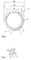
- the functional component a cam 1a according to FIG. 1, an eccentric disc 1b corresponding to FIG. 2 or else a bearing ring, a sensor ring, a drive wheel or another element, has an inner recess A for receiving the support shaft 2 with an opening diameter d1 (see FIG. 4).
- the diameter d1 for the joint length L is constant.
- the inner recess has an inlet chamfer 4, which has an opening diameter d2 at its mouth and merges into the opening diameter d1 of the recess A.
- the recess A of the functional component 1 has a substantially circular cross section and the surface 6 of the inner recess A is preferably smooth.
- the surface 6 of the inner recess A no corners or other points of discontinuity in the circumferential direction.
- the recess A has a circular cross-section, as can be produced during roughing, drilling, sintering or even forging without reworking. It is understood that the terms “round”, “circular” and “smooth” are not to be understood in a strictly mathematical sense, but that the shape of the recess may differ from the pure circular shape due to manufacturing tolerances and unavoidable technical inaccuracies.
- the proposed solution uses the entire circumference of the recess A to build the force and positive engagement.
- FIG. 3 shows two conical sections arranged successively in the direction of the carrier shaft axis 9 with outwardly pointing cone angles ⁇ 1, ⁇ 2, which increase towards the end face of the cam, preferably by three to seven times.
- FIG. 4 shows an entry radius r as the entry chamfer.
- the support shaft 2, with an outer diameter D1 is widened in the region 3, on which the functional component 1 is to be joined, by means of Rändet to the diameter D2.
- elevations 7 and depressions 8 are formed by the knurl operation (compare FIGS. 6, 7), wherein the inner diameter Di is not or only very slightly reduced.
- the elevations 7 are divided into two Rändeleinintervention 11 and a survey length 10 between the Rändeleinverbn eleventh
- the joining operation takes place in such a way that, according to FIG. 5, the functional component 1 with its inlet chamfer 4 is first pushed over the widened region 3 of the support shaft 2 in the direction indicated by the arrow, thereby forming a frictional and positive connection with the support shaft.
- the invention is based on the finding that when forming a positive and positive connection between the functional component 1 and the support shaft 2, the greatest torques can be transmitted.
- chip formation must be avoided as far as possible, since experiments have shown that the transmittable torque is reduced by chip formation, since material is broken out of the joint gap and thus no longer for positive locking or stress build-up and thus contribute to the adhesion.
- care must be taken that each volume region in the joining zone is deformed only once at most during the pressing-on operation. Otherwise, cavities and stress losses can occur and thus the reduction in the form and / or adhesion.
- the elevations 7 in the expanded area of the support shaft 2 as closely as possible in the longitudinal direction of the support shaft 2 and thus aligned parallel to the axis 9 of the support shaft.
- the elevations 7 over their entire length 10, apart from the area of the knurling inlet 11, as constant as possible height and cross-sectional shape.
- this means that the elevations are formed over the largest possible length with a constant cross-section.
- the elevations 7 in the region of the knurling inlet 11 are smaller in relation to height and cross section than in the remaining region 10 of the widening 3.
- the elevations 7 are hard as possible, which can be done, for example, already by the work hardening of the supporting shaft material during knurling.
- this strain hardening can be increased.
- the surveys must not be formed too pointed, because it favors the formation of chips. That is, the radii 13 of the elevation tips 12 should not be too small.
- the cross-sectional contour can be described by the elevation 7 and recess 8 as approximately as possible by two semicircles with the radius 13 merging into one another, as shown schematically in FIG.
- the insertion chamfer 4 is not embodied on the recess of the functional component or is designed to be reduced to a simple edge break or deburring.
- a specially shaped knurled neck 11 performs this function.
- the knurled run-in 11 is formed in this embodiment such that the diameter described by the elevations 7, starting from the edge of the knurling over which the functional component is pushed during assembly, increases in a funnel-like manner.
- the diameter D3 at the edge of the knurling is smaller and the largest diameter of the knurling inlet 11 is larger than the diameter d1 of the recess A of the functional component.
- the axial diameter profile of the widened region 3 of the support shaft 2 is analogous to the above-described funnel-like widening of the recess A of the functional component.
- the advantage of this design is that the functional component does not have to be provided with an inlet chamfer.
- such knurls are more expensive to manufacture, so that a decision must be made depending on the specific application.
- the functional component 1 is not plastically widened by being pushed onto the widened region of the support shaft, but only slightly elastically. As a result, the functional component undergoes less tensile stress, as a result of which the danger of cracking decreases and the fluctuation of the geometry of the outer surface 5 of the functional component 1 is reduced.
- these widening on the outer surface of the functional component 1 in diameter should not exceed a dimension of 0.2 mm. Expansion diameters of less than 0.05 mm are preferred, and in the ideal case no widening measurable on the outer circumference is provided.
- the assembly process proposed in the present invention has a number of advantages.
- Cams can be produced for example by sintering, but also by cold or hot forging with almost no rework.
- the inlet chamfer can be molded directly into the production process.
- Elaborate reworking by means of rooms and sometimes even the reworking by means of turning can be dispensed with. Neither small teeth, nor ovalities, nor polygonal inner contours need to be introduced into the recess.
- the functional component When the functional component is pressed in, a uniform material deformation of the functional component material takes place in the region of the recess, so that voltage peaks are avoided.
- the material on the surface of the inner recess is displaced by the elevations on the support shaft, thereby flowing around the elevations around.
- the material Even partially flows into the depressions 8 on the support shaft 2. This creates a very good fit.
- the residual elasticities of the plastic local deformations due to the resilience of the material of the functional component contribute to the frictional connection, even if the functional component has not been widened at all by the pushing on.
- the elevations 7 are quasi clamped at their side edges by the plastically molded around them material of the functional component.
- the functional component is additionally slightly elastic, not plastic, widened, so that additional contributions to a traction are provided because of the material spring back.
- the camshafts produced by this method were particularly well the alternating loads caused by the alternating torque during engine operation stood.
- the large-scale positive engagement with the elastic bias leads to the fact that the distance between the tolerable static loads reduced to the sustainable dynamic alternating loads.
- the force increase during the pressing-on phase of the functional component on the widened wave region is almost constant, at least monotonously increasing, so that a very good and simple quality control (ie control of the joining process by measuring and monitoring the course of the pressing force) is made possible.
Landscapes
- Engineering & Computer Science (AREA)
- General Engineering & Computer Science (AREA)
- Mechanical Engineering (AREA)
- Valve-Gear Or Valve Arrangements (AREA)
- Gears, Cams (AREA)
Priority Applications (11)
| Application Number | Priority Date | Filing Date | Title |
|---|---|---|---|
| AT05013219T ATE478269T1 (de) | 2005-06-20 | 2005-06-20 | Gebaute nockenwelle |
| DE502005010107T DE502005010107D1 (de) | 2005-06-20 | 2005-06-20 | Gebaute Nockenwelle |
| ES05013219T ES2349396T3 (es) | 2005-06-20 | 2005-06-20 | Árbol de levas compuesto. |
| EP05013219A EP1741945B1 (fr) | 2005-06-20 | 2005-06-20 | Arbre à cames assemblé |
| KR1020077029789A KR101320178B1 (ko) | 2005-06-20 | 2006-05-23 | 조립된 캠 샤프트 |
| MX2007013373A MX2007013373A (es) | 2005-06-20 | 2006-05-23 | Arbol de leva ensamblado. |
| JP2008517349A JP2008546943A (ja) | 2005-06-20 | 2006-05-23 | 組み立てられたカムシャフト |
| US11/993,138 US8402650B2 (en) | 2005-06-20 | 2006-05-23 | Built-up camshaft |
| DE212006000020U DE212006000020U1 (de) | 2005-06-20 | 2006-05-23 | Gebaute Nockenwelle |
| PCT/EP2006/004865 WO2006136252A1 (fr) | 2005-06-20 | 2006-05-23 | Arbres a cames construit |
| CN2006800222458A CN101268293B (zh) | 2005-06-20 | 2006-05-23 | 组合的凸轮轴 |
Applications Claiming Priority (1)
| Application Number | Priority Date | Filing Date | Title |
|---|---|---|---|
| EP05013219A EP1741945B1 (fr) | 2005-06-20 | 2005-06-20 | Arbre à cames assemblé |
Publications (2)
| Publication Number | Publication Date |
|---|---|
| EP1741945A1 true EP1741945A1 (fr) | 2007-01-10 |
| EP1741945B1 EP1741945B1 (fr) | 2010-08-18 |
Family
ID=35170005
Family Applications (1)
| Application Number | Title | Priority Date | Filing Date |
|---|---|---|---|
| EP05013219A Active EP1741945B1 (fr) | 2005-06-20 | 2005-06-20 | Arbre à cames assemblé |
Country Status (10)
| Country | Link |
|---|---|
| US (1) | US8402650B2 (fr) |
| EP (1) | EP1741945B1 (fr) |
| JP (1) | JP2008546943A (fr) |
| KR (1) | KR101320178B1 (fr) |
| CN (1) | CN101268293B (fr) |
| AT (1) | ATE478269T1 (fr) |
| DE (2) | DE502005010107D1 (fr) |
| ES (1) | ES2349396T3 (fr) |
| MX (1) | MX2007013373A (fr) |
| WO (1) | WO2006136252A1 (fr) |
Cited By (8)
| Publication number | Priority date | Publication date | Assignee | Title |
|---|---|---|---|---|
| DE102008024877A1 (de) | 2008-05-23 | 2009-11-26 | Audi Ag | Gebaute Nockenwelle |
| WO2010142408A1 (fr) | 2009-06-10 | 2010-12-16 | Audi Ag | Élément d'arbre assemblé, notamment arbre à cames assemblé pour moteurs à combustion interne à commande par soupapes |
| US7887069B2 (en) | 2007-04-19 | 2011-02-15 | Thyssenkrupp Presta Aktiengesellschaft | Toothed rack or threaded rod |
| WO2012051991A1 (fr) * | 2010-10-12 | 2012-04-26 | Neumayer Tekfor Holding Gmbh | Fabrication d'un arbre fonctionnel |
| US8905436B2 (en) | 2010-02-22 | 2014-12-09 | Thyssenkrupp Presta Aktiengesellschaft | Adjustable steering column for a motor vehicle |
| WO2015085340A3 (fr) * | 2013-12-10 | 2015-08-06 | Asmag-Holding Gmbh | Système d'entraînement et installation de profilage équipée de celui-ci |
| EP2772656A3 (fr) * | 2013-03-01 | 2017-05-03 | The Boeing Company | Accouplement à friction |
| WO2020244705A1 (fr) * | 2019-06-05 | 2020-12-10 | Schaeffler Technologies AG & Co. KG | Arbre à cames comportant un canal d'huile, déphaseur d'arbre à cames comportant un arbre à cames et procédé de montage de déphaseur d'arbre à cames |
Families Citing this family (19)
| Publication number | Priority date | Publication date | Assignee | Title |
|---|---|---|---|---|
| JP5243830B2 (ja) * | 2008-03-28 | 2013-07-24 | 東海ゴム工業株式会社 | 配管フランジ継手 |
| DE102009014895B4 (de) | 2009-03-25 | 2012-05-24 | Audi Ag | Welle-Nabe-Verbindung |
| DE102010039008A1 (de) * | 2010-08-06 | 2012-02-09 | Hirschvogel Umformtechnik Gmbh | Rotor und Herstellungsverfahren hierzu |
| JP2014020381A (ja) * | 2012-07-12 | 2014-02-03 | Kubota Corp | 焼結金属伝動輪 |
| DE102012017040A1 (de) * | 2012-08-29 | 2014-03-27 | Gkn Sinter Metals Holding Gmbh | Verfahren zur Herstellung eines Verbundbauteils sowie ein Verbundbauteil |
| DE102013012384A1 (de) * | 2013-07-25 | 2015-01-29 | Man Truck & Bus Ag | Verfahren zum Fertigen einer gebauten Nockenwelle |
| CN103437843B (zh) * | 2013-08-28 | 2016-01-27 | 中国北方发动机研究所(天津) | 一种组合式凸轮轴 |
| DE102014000809B3 (de) * | 2014-01-22 | 2014-11-20 | Iav Gmbh Ingenieurgesellschaft Auto Und Verkehr | Verfahren zum Herstellen einer Welle-Nabe-Verbindung |
| CN103912415A (zh) * | 2014-04-22 | 2014-07-09 | 无锡隆盛科技股份有限公司 | 一种汽油发动机电动egr阀的中心杆端盖结构 |
| DE102015101004B4 (de) * | 2015-01-23 | 2017-05-18 | Linamar Gmbh | Verfahren zum Fügen einer Funktionsbaugruppe sowie Funktionsbaugruppe |
| DE102016208968A1 (de) * | 2016-05-24 | 2017-11-30 | Thyssenkrupp Ag | Schiebemodul einer Nockenwelle |
| DE102017201578B4 (de) | 2017-02-01 | 2024-02-15 | Thyssenkrupp Ag | Welle-Nabe-Verbund und Verfahren zur Erzeugung eines Welle-Nabe-Verbundes |
| CN108049927A (zh) * | 2018-01-19 | 2018-05-18 | 亚新科凸轮轴(仪征)有限公司 | 组装凸轮轴及其制造方法 |
| CN108788717B (zh) * | 2018-06-14 | 2021-04-06 | 成都金顶精密铸造有限公司 | 一种组合式凸轮轴的装配方法 |
| DE102019103611A1 (de) * | 2019-02-13 | 2020-08-13 | Schaeffler Technologies AG & Co. KG | Nockenwellenmontageverfahren und zugehöriges Nockenwellenverstellsystem |
| MX2021015482A (es) * | 2019-06-14 | 2022-01-24 | Gkn Driveline Deutschland Gmbh | Metodo para producir un sistema de dentado de engranaje y componente de una conexion de vastago/cubo. |
| CN111250925A (zh) * | 2020-03-27 | 2020-06-09 | 浙江赛克思液压有限公司 | 一种轴承位过盈装配滚花工艺及其滚花轴 |
| DE102020111679A1 (de) * | 2020-04-29 | 2021-11-04 | Valeo Siemens Eautomotive Germany Gmbh | Welle, Umformwerkzeug, Herstellungsverfahren und Rotor für eine elektrische Maschine |
| DE102020208164A1 (de) | 2020-06-30 | 2021-12-30 | Thyssenkrupp Ag | Lenksäule für ein Kraftfahrzeug und Verfahren zur Einstellung einer Lenksäule |
Citations (8)
| Publication number | Priority date | Publication date | Assignee | Title |
|---|---|---|---|---|
| US3734697A (en) * | 1970-07-13 | 1973-05-22 | Roth Co Roy E | Pump impeller making |
| DE2333040A1 (de) * | 1973-06-29 | 1975-01-23 | Lemfoerder Metallwaren Ag | Feste verbindung eines wellenzapfens mit der nabe eines anschlussorgans, beispielsweise der gabel eines drehgelenks |
| US4376333A (en) * | 1978-06-21 | 1983-03-15 | Hitachi, Ltd. | Method of joining members of metal by forced insertion |
| US4630498A (en) * | 1982-07-30 | 1986-12-23 | Briggs & Stratton Corp. | Laminated wheel assembly |
| DE4218624A1 (de) * | 1991-06-07 | 1992-12-10 | Nippon Piston Ring Co Ltd | Mechanisches element mit einer welle, die sich mit einer presspassung in einem aufnehmenden glied befindet und dessen herstellungsverfahren |
| FR2704164A1 (fr) * | 1993-04-19 | 1994-10-28 | Sankyo Seiki Seisakusho Kk | Corps rotatif en résine à arbre métallique. |
| US6416245B1 (en) * | 1998-05-04 | 2002-07-09 | Thyssen Krupp Automotive Ag | Device comprising a shaft and at least one hub which is attached to said shaft, and a method for producing this device |
| WO2004076095A1 (fr) * | 2003-02-27 | 2004-09-10 | Mitsuba Corporation | Arbre et dispositif pour façonner un arbre |
Family Cites Families (12)
| Publication number | Priority date | Publication date | Assignee | Title |
|---|---|---|---|---|
| FR2630790B1 (fr) | 1988-04-28 | 1994-04-08 | Valtubes | Procede d'assemblage d'un arbre a cames rapportees et arbre a cames ainsi obtenu |
| DE4121951C1 (fr) | 1991-07-03 | 1992-12-24 | Supervis Ets | |
| JPH06312322A (ja) * | 1993-04-26 | 1994-11-08 | Mitsubishi Materials Corp | 中空可動軸およびその製造方法 |
| CN2200080Y (zh) * | 1994-07-25 | 1995-06-07 | 何其昌 | 镶铸钢齿轮的铸铁凸轮轴 |
| JPH08121120A (ja) * | 1994-08-31 | 1996-05-14 | Nippon Piston Ring Co Ltd | シャフトを嵌合部材に圧入してなる機械要素 |
| JPH0874870A (ja) * | 1994-08-31 | 1996-03-19 | Nippon Piston Ring Co Ltd | シャフトを嵌合部材に圧入してなる機械要素 |
| JPH0874871A (ja) * | 1994-09-06 | 1996-03-19 | Nippon Piston Ring Co Ltd | シャフトを嵌合部材に圧入してなる機械要素 |
| JPH08178020A (ja) * | 1994-12-27 | 1996-07-12 | Nippon Piston Ring Co Ltd | カムにシャフトを圧入嵌合してなる組立カムシャフト |
| JPH08270409A (ja) * | 1995-03-31 | 1996-10-15 | Isuzu Motors Ltd | 組立式カムシャフトの組み立て方法 |
| DE19925028A1 (de) * | 1999-06-01 | 2000-12-21 | Thyssen Krupp Automotive Ag | Nocken für zusammengesetzte Nockenwelle |
| EP1387102A1 (fr) * | 2002-07-31 | 2004-02-04 | Robert Bürgler | Joint arbre-moyeu à pression |
| CN1616188A (zh) * | 2003-11-13 | 2005-05-18 | 扬动股份有限公司 | 柴油机凸轮轴机械加工工艺 |
-
2005
- 2005-06-20 ES ES05013219T patent/ES2349396T3/es active Active
- 2005-06-20 EP EP05013219A patent/EP1741945B1/fr active Active
- 2005-06-20 DE DE502005010107T patent/DE502005010107D1/de active Active
- 2005-06-20 AT AT05013219T patent/ATE478269T1/de active
-
2006
- 2006-05-23 US US11/993,138 patent/US8402650B2/en active Active
- 2006-05-23 DE DE212006000020U patent/DE212006000020U1/de not_active Expired - Lifetime
- 2006-05-23 KR KR1020077029789A patent/KR101320178B1/ko active IP Right Grant
- 2006-05-23 MX MX2007013373A patent/MX2007013373A/es active IP Right Grant
- 2006-05-23 WO PCT/EP2006/004865 patent/WO2006136252A1/fr active Application Filing
- 2006-05-23 JP JP2008517349A patent/JP2008546943A/ja active Pending
- 2006-05-23 CN CN2006800222458A patent/CN101268293B/zh not_active Expired - Fee Related
Patent Citations (8)
| Publication number | Priority date | Publication date | Assignee | Title |
|---|---|---|---|---|
| US3734697A (en) * | 1970-07-13 | 1973-05-22 | Roth Co Roy E | Pump impeller making |
| DE2333040A1 (de) * | 1973-06-29 | 1975-01-23 | Lemfoerder Metallwaren Ag | Feste verbindung eines wellenzapfens mit der nabe eines anschlussorgans, beispielsweise der gabel eines drehgelenks |
| US4376333A (en) * | 1978-06-21 | 1983-03-15 | Hitachi, Ltd. | Method of joining members of metal by forced insertion |
| US4630498A (en) * | 1982-07-30 | 1986-12-23 | Briggs & Stratton Corp. | Laminated wheel assembly |
| DE4218624A1 (de) * | 1991-06-07 | 1992-12-10 | Nippon Piston Ring Co Ltd | Mechanisches element mit einer welle, die sich mit einer presspassung in einem aufnehmenden glied befindet und dessen herstellungsverfahren |
| FR2704164A1 (fr) * | 1993-04-19 | 1994-10-28 | Sankyo Seiki Seisakusho Kk | Corps rotatif en résine à arbre métallique. |
| US6416245B1 (en) * | 1998-05-04 | 2002-07-09 | Thyssen Krupp Automotive Ag | Device comprising a shaft and at least one hub which is attached to said shaft, and a method for producing this device |
| WO2004076095A1 (fr) * | 2003-02-27 | 2004-09-10 | Mitsuba Corporation | Arbre et dispositif pour façonner un arbre |
Cited By (12)
| Publication number | Priority date | Publication date | Assignee | Title |
|---|---|---|---|---|
| US7887069B2 (en) | 2007-04-19 | 2011-02-15 | Thyssenkrupp Presta Aktiengesellschaft | Toothed rack or threaded rod |
| DE102008024877A1 (de) | 2008-05-23 | 2009-11-26 | Audi Ag | Gebaute Nockenwelle |
| WO2010142408A1 (fr) | 2009-06-10 | 2010-12-16 | Audi Ag | Élément d'arbre assemblé, notamment arbre à cames assemblé pour moteurs à combustion interne à commande par soupapes |
| DE102009024455A1 (de) | 2009-06-10 | 2011-01-05 | Audi Ag | Gebautes Wellenelement, insbesondere gebaute Nockenwelle für ventilgesteuerte Brennkraftmaschinen |
| US8662043B2 (en) | 2009-06-10 | 2014-03-04 | Audi Ag | Assembled shaft element, particularly assembled camshaft for valve-controlled internal combustion engines |
| US8905436B2 (en) | 2010-02-22 | 2014-12-09 | Thyssenkrupp Presta Aktiengesellschaft | Adjustable steering column for a motor vehicle |
| WO2012051991A1 (fr) * | 2010-10-12 | 2012-04-26 | Neumayer Tekfor Holding Gmbh | Fabrication d'un arbre fonctionnel |
| CN103153530A (zh) * | 2010-10-12 | 2013-06-12 | 诺伊曼尔·泰克福尔控股有限公司 | 功能轴的制造 |
| EP2772656A3 (fr) * | 2013-03-01 | 2017-05-03 | The Boeing Company | Accouplement à friction |
| US10208775B2 (en) | 2013-03-01 | 2019-02-19 | The Boeing Company | Methods of frictional coupling |
| WO2015085340A3 (fr) * | 2013-12-10 | 2015-08-06 | Asmag-Holding Gmbh | Système d'entraînement et installation de profilage équipée de celui-ci |
| WO2020244705A1 (fr) * | 2019-06-05 | 2020-12-10 | Schaeffler Technologies AG & Co. KG | Arbre à cames comportant un canal d'huile, déphaseur d'arbre à cames comportant un arbre à cames et procédé de montage de déphaseur d'arbre à cames |
Also Published As
| Publication number | Publication date |
|---|---|
| CN101268293B (zh) | 2011-01-26 |
| ES2349396T3 (es) | 2010-12-30 |
| JP2008546943A (ja) | 2008-12-25 |
| MX2007013373A (es) | 2008-03-14 |
| WO2006136252A1 (fr) | 2006-12-28 |
| EP1741945B1 (fr) | 2010-08-18 |
| US20100224145A1 (en) | 2010-09-09 |
| CN101268293A (zh) | 2008-09-17 |
| ATE478269T1 (de) | 2010-09-15 |
| DE502005010107D1 (de) | 2010-09-30 |
| DE212006000020U1 (de) | 2007-11-08 |
| KR20080016661A (ko) | 2008-02-21 |
| KR101320178B1 (ko) | 2013-10-22 |
| US8402650B2 (en) | 2013-03-26 |
Similar Documents
| Publication | Publication Date | Title |
|---|---|---|
| EP1741945B1 (fr) | Arbre à cames assemblé | |
| EP0521354B1 (fr) | Arbre à cames pour le contrôle des soupapes dans les moteurs à combustion interne | |
| DE4218624C2 (de) | Mechanisches Element mit einer Welle, die sich unter Druck in mindestens ein zusammengesetztes Eingriffsbauteil eingepaßt ist sowie dessen Herstellungsverfahren | |
| DE3717190C2 (fr) | ||
| DE68905065T2 (de) | Nockenwellenzusammenbauverfahren und so hergestellte nockenwelle. | |
| EP2440808B1 (fr) | Procédé de fabrication d'un arbre à cames | |
| EP1568554B1 (fr) | Manchon d'immobilisation pour un colonne de direction | |
| DE102007018920B3 (de) | Antriebswelle | |
| DE102004009074B3 (de) | Gebauter Mehrfachnocken | |
| EP1723316B1 (fr) | Arbre a cames et procede pour produire un arbre a cames | |
| DE19710847C2 (de) | Zusammengesetzte Steuerwelle und Verfahren für deren Herstellung | |
| EP2869947B1 (fr) | Procédé pour produire un élément de connexion pour transmettre des mouvements de rotation et élément de connexion ainsi produit | |
| WO2018055176A1 (fr) | Procédé de fabrication d'un arbre de rotor et arbre de rotor | |
| EP1502011B1 (fr) | Came monobloc, son procede de fabrication, et assemblage d'un arbre de commande ou arbre a came | |
| WO1999057450A1 (fr) | Dispositif comportant un arbre pourvu d'au moins un moyeu, ainsi que procede pour la fabrication de ce dispositif | |
| WO2008074560A2 (fr) | Procédé de fabrication d'un anneau de synchronisation d'un dispositif de synchronisation | |
| WO1995023911A1 (fr) | Cames multiples | |
| EP2082146B1 (fr) | Assemblage d'un arbre de transmission | |
| DE102004062518B4 (de) | Nocken für gebaute Nockenwellen | |
| WO2001094802A1 (fr) | Dispositif dote d"un arbre et d"au moins un moyeu dispose sur cet arbre, et procede de fabrication de ce dispositif | |
| WO2007088117A1 (fr) | Goujon pour entrainement a planetaires et procede d'usinage de son extremite | |
| DE102006035082A1 (de) | Verfahren und Vorrichtung zur Herstellung einer Welle-Nabe-Verbindung | |
| EP3173184B1 (fr) | Procédé de fabrication d'une bague de synchronisation à double cône | |
| EP2338620B1 (fr) | Composant à rotation symétrique obtenu par l'assemblage de deux pièces et son procédé de fabrication | |
| DE202020003646U1 (de) | Distanzelement für einen Kraftstoffverteiler sowie Kraftstoffverteiler |
Legal Events
| Date | Code | Title | Description |
|---|---|---|---|
| PUAI | Public reference made under article 153(3) epc to a published international application that has entered the european phase |
Free format text: ORIGINAL CODE: 0009012 |
|
| 17P | Request for examination filed |
Effective date: 20060222 |
|
| AK | Designated contracting states |
Kind code of ref document: A1 Designated state(s): AT BE BG CH CY CZ DE DK EE ES FI FR GB GR HU IE IS IT LI LT LU MC NL PL PT RO SE SI SK TR |
|
| AX | Request for extension of the european patent |
Extension state: AL BA HR LV MK YU |
|
| RAP1 | Party data changed (applicant data changed or rights of an application transferred) |
Owner name: THYSSENKRUPP PRESTA AG |
|
| AKX | Designation fees paid |
Designated state(s): AT BE BG CH CY CZ DE DK EE ES FI FR GB GR HU IE IS IT LI LT LU MC NL PL PT RO SE SI SK TR |
|
| AXX | Extension fees paid |
Extension state: YU Payment date: 20070710 Extension state: HR Payment date: 20070710 Extension state: BA Payment date: 20070710 Extension state: AL Payment date: 20070710 Extension state: MK Payment date: 20070710 |
|
| RAP1 | Party data changed (applicant data changed or rights of an application transferred) |
Owner name: THYSSENKRUPP PRESTA TECCENTER AG |
|
| GRAP | Despatch of communication of intention to grant a patent |
Free format text: ORIGINAL CODE: EPIDOSNIGR1 |
|
| GRAS | Grant fee paid |
Free format text: ORIGINAL CODE: EPIDOSNIGR3 |
|
| GRAA | (expected) grant |
Free format text: ORIGINAL CODE: 0009210 |
|
| AK | Designated contracting states |
Kind code of ref document: B1 Designated state(s): AT BE BG CH CY CZ DE DK EE ES FI FR GB GR HU IE IS IT LI LT LU MC NL PL PT RO SE SI SK TR |
|
| REG | Reference to a national code |
Ref country code: GB Ref legal event code: FG4D Free format text: NOT ENGLISH |
|
| REG | Reference to a national code |
Ref country code: CH Ref legal event code: EP |
|
| REG | Reference to a national code |
Ref country code: IE Ref legal event code: FG4D Free format text: LANGUAGE OF EP DOCUMENT: GERMAN |
|
| REF | Corresponds to: |
Ref document number: 502005010107 Country of ref document: DE Date of ref document: 20100930 Kind code of ref document: P |
|
| REG | Reference to a national code |
Ref country code: NL Ref legal event code: VDEP Effective date: 20100818 |
|
| REG | Reference to a national code |
Ref country code: ES Ref legal event code: FG2A Effective date: 20101217 |
|
| LTIE | Lt: invalidation of european patent or patent extension |
Effective date: 20100818 |
|
| PG25 | Lapsed in a contracting state [announced via postgrant information from national office to epo] |
Ref country code: LT Free format text: LAPSE BECAUSE OF FAILURE TO SUBMIT A TRANSLATION OF THE DESCRIPTION OR TO PAY THE FEE WITHIN THE PRESCRIBED TIME-LIMIT Effective date: 20100818 Ref country code: FI Free format text: LAPSE BECAUSE OF FAILURE TO SUBMIT A TRANSLATION OF THE DESCRIPTION OR TO PAY THE FEE WITHIN THE PRESCRIBED TIME-LIMIT Effective date: 20100818 |
|
| PG25 | Lapsed in a contracting state [announced via postgrant information from national office to epo] |
Ref country code: PT Free format text: LAPSE BECAUSE OF FAILURE TO SUBMIT A TRANSLATION OF THE DESCRIPTION OR TO PAY THE FEE WITHIN THE PRESCRIBED TIME-LIMIT Effective date: 20101220 Ref country code: SI Free format text: LAPSE BECAUSE OF FAILURE TO SUBMIT A TRANSLATION OF THE DESCRIPTION OR TO PAY THE FEE WITHIN THE PRESCRIBED TIME-LIMIT Effective date: 20100818 Ref country code: IS Free format text: LAPSE BECAUSE OF FAILURE TO SUBMIT A TRANSLATION OF THE DESCRIPTION OR TO PAY THE FEE WITHIN THE PRESCRIBED TIME-LIMIT Effective date: 20101218 Ref country code: CY Free format text: LAPSE BECAUSE OF FAILURE TO SUBMIT A TRANSLATION OF THE DESCRIPTION OR TO PAY THE FEE WITHIN THE PRESCRIBED TIME-LIMIT Effective date: 20100818 Ref country code: BG Free format text: LAPSE BECAUSE OF FAILURE TO SUBMIT A TRANSLATION OF THE DESCRIPTION OR TO PAY THE FEE WITHIN THE PRESCRIBED TIME-LIMIT Effective date: 20101118 Ref country code: PL Free format text: LAPSE BECAUSE OF FAILURE TO SUBMIT A TRANSLATION OF THE DESCRIPTION OR TO PAY THE FEE WITHIN THE PRESCRIBED TIME-LIMIT Effective date: 20100818 |
|
| REG | Reference to a national code |
Ref country code: IE Ref legal event code: FD4D |
|
| PG25 | Lapsed in a contracting state [announced via postgrant information from national office to epo] |
Ref country code: SE Free format text: LAPSE BECAUSE OF FAILURE TO SUBMIT A TRANSLATION OF THE DESCRIPTION OR TO PAY THE FEE WITHIN THE PRESCRIBED TIME-LIMIT Effective date: 20100818 Ref country code: NL Free format text: LAPSE BECAUSE OF FAILURE TO SUBMIT A TRANSLATION OF THE DESCRIPTION OR TO PAY THE FEE WITHIN THE PRESCRIBED TIME-LIMIT Effective date: 20100818 Ref country code: GR Free format text: LAPSE BECAUSE OF FAILURE TO SUBMIT A TRANSLATION OF THE DESCRIPTION OR TO PAY THE FEE WITHIN THE PRESCRIBED TIME-LIMIT Effective date: 20101119 |
|
| PG25 | Lapsed in a contracting state [announced via postgrant information from national office to epo] |
Ref country code: DK Free format text: LAPSE BECAUSE OF FAILURE TO SUBMIT A TRANSLATION OF THE DESCRIPTION OR TO PAY THE FEE WITHIN THE PRESCRIBED TIME-LIMIT Effective date: 20100818 Ref country code: IE Free format text: LAPSE BECAUSE OF FAILURE TO SUBMIT A TRANSLATION OF THE DESCRIPTION OR TO PAY THE FEE WITHIN THE PRESCRIBED TIME-LIMIT Effective date: 20100818 |
|
| PG25 | Lapsed in a contracting state [announced via postgrant information from national office to epo] |
Ref country code: SK Free format text: LAPSE BECAUSE OF FAILURE TO SUBMIT A TRANSLATION OF THE DESCRIPTION OR TO PAY THE FEE WITHIN THE PRESCRIBED TIME-LIMIT Effective date: 20100818 Ref country code: EE Free format text: LAPSE BECAUSE OF FAILURE TO SUBMIT A TRANSLATION OF THE DESCRIPTION OR TO PAY THE FEE WITHIN THE PRESCRIBED TIME-LIMIT Effective date: 20100818 Ref country code: RO Free format text: LAPSE BECAUSE OF FAILURE TO SUBMIT A TRANSLATION OF THE DESCRIPTION OR TO PAY THE FEE WITHIN THE PRESCRIBED TIME-LIMIT Effective date: 20100818 |
|
| PLBE | No opposition filed within time limit |
Free format text: ORIGINAL CODE: 0009261 |
|
| STAA | Information on the status of an ep patent application or granted ep patent |
Free format text: STATUS: NO OPPOSITION FILED WITHIN TIME LIMIT |
|
| 26N | No opposition filed |
Effective date: 20110519 |
|
| REG | Reference to a national code |
Ref country code: DE Ref legal event code: R097 Ref document number: 502005010107 Country of ref document: DE Effective date: 20110519 |
|
| BERE | Be: lapsed |
Owner name: THYSSENKRUPP PRESTA TECCENTER AG Effective date: 20110630 |
|
| REG | Reference to a national code |
Ref country code: CH Ref legal event code: PL |
|
| PG25 | Lapsed in a contracting state [announced via postgrant information from national office to epo] |
Ref country code: BE Free format text: LAPSE BECAUSE OF NON-PAYMENT OF DUE FEES Effective date: 20110630 |
|
| PG25 | Lapsed in a contracting state [announced via postgrant information from national office to epo] |
Ref country code: LI Free format text: LAPSE BECAUSE OF NON-PAYMENT OF DUE FEES Effective date: 20110630 Ref country code: CH Free format text: LAPSE BECAUSE OF NON-PAYMENT OF DUE FEES Effective date: 20110630 |
|
| REG | Reference to a national code |
Ref country code: AT Ref legal event code: MM01 Ref document number: 478269 Country of ref document: AT Kind code of ref document: T Effective date: 20110620 |
|
| PGFP | Annual fee paid to national office [announced via postgrant information from national office to epo] |
Ref country code: ES Payment date: 20120627 Year of fee payment: 8 |
|
| PG25 | Lapsed in a contracting state [announced via postgrant information from national office to epo] |
Ref country code: AT Free format text: LAPSE BECAUSE OF NON-PAYMENT OF DUE FEES Effective date: 20110620 |
|
| PG25 | Lapsed in a contracting state [announced via postgrant information from national office to epo] |
Ref country code: MC Free format text: LAPSE BECAUSE OF NON-PAYMENT OF DUE FEES Effective date: 20110630 |
|
| PG25 | Lapsed in a contracting state [announced via postgrant information from national office to epo] |
Ref country code: LU Free format text: LAPSE BECAUSE OF NON-PAYMENT OF DUE FEES Effective date: 20110620 |
|
| PGFP | Annual fee paid to national office [announced via postgrant information from national office to epo] |
Ref country code: CZ Payment date: 20130613 Year of fee payment: 9 |
|
| PG25 | Lapsed in a contracting state [announced via postgrant information from national office to epo] |
Ref country code: TR Free format text: LAPSE BECAUSE OF FAILURE TO SUBMIT A TRANSLATION OF THE DESCRIPTION OR TO PAY THE FEE WITHIN THE PRESCRIBED TIME-LIMIT Effective date: 20100818 |
|
| PG25 | Lapsed in a contracting state [announced via postgrant information from national office to epo] |
Ref country code: HU Free format text: LAPSE BECAUSE OF FAILURE TO SUBMIT A TRANSLATION OF THE DESCRIPTION OR TO PAY THE FEE WITHIN THE PRESCRIBED TIME-LIMIT Effective date: 20100818 |
|
| PG25 | Lapsed in a contracting state [announced via postgrant information from national office to epo] |
Ref country code: CZ Free format text: LAPSE BECAUSE OF NON-PAYMENT OF DUE FEES Effective date: 20140620 |
|
| REG | Reference to a national code |
Ref country code: ES Ref legal event code: FD2A Effective date: 20150727 |
|
| PG25 | Lapsed in a contracting state [announced via postgrant information from national office to epo] |
Ref country code: ES Free format text: LAPSE BECAUSE OF NON-PAYMENT OF DUE FEES Effective date: 20140621 |
|
| REG | Reference to a national code |
Ref country code: FR Ref legal event code: PLFP Year of fee payment: 12 |
|
| REG | Reference to a national code |
Ref country code: FR Ref legal event code: PLFP Year of fee payment: 13 |
|
| REG | Reference to a national code |
Ref country code: FR Ref legal event code: PLFP Year of fee payment: 14 |
|
| P01 | Opt-out of the competence of the unified patent court (upc) registered |
Effective date: 20230530 |
|
| PGFP | Annual fee paid to national office [announced via postgrant information from national office to epo] |
Ref country code: IT Payment date: 20230623 Year of fee payment: 19 |
|
| PGFP | Annual fee paid to national office [announced via postgrant information from national office to epo] |
Ref country code: GB Payment date: 20240619 Year of fee payment: 20 |
|
| PGFP | Annual fee paid to national office [announced via postgrant information from national office to epo] |
Ref country code: DE Payment date: 20240619 Year of fee payment: 20 |
|
| PGFP | Annual fee paid to national office [announced via postgrant information from national office to epo] |
Ref country code: FR Payment date: 20240628 Year of fee payment: 20 |