EP1740861B1 - Metallischer abzug - Google Patents
Metallischer abzug Download PDFInfo
- Publication number
- EP1740861B1 EP1740861B1 EP05735508A EP05735508A EP1740861B1 EP 1740861 B1 EP1740861 B1 EP 1740861B1 EP 05735508 A EP05735508 A EP 05735508A EP 05735508 A EP05735508 A EP 05735508A EP 1740861 B1 EP1740861 B1 EP 1740861B1
- Authority
- EP
- European Patent Office
- Prior art keywords
- vent
- porous polymeric
- polymeric membrane
- membrane
- shell
- Prior art date
- Legal status (The legal status is an assumption and is not a legal conclusion. Google has not performed a legal analysis and makes no representation as to the accuracy of the status listed.)
- Not-in-force
Links
Images

Classifications
-
- F—MECHANICAL ENGINEERING; LIGHTING; HEATING; WEAPONS; BLASTING
- F16—ENGINEERING ELEMENTS AND UNITS; GENERAL MEASURES FOR PRODUCING AND MAINTAINING EFFECTIVE FUNCTIONING OF MACHINES OR INSTALLATIONS; THERMAL INSULATION IN GENERAL
- F16K—VALVES; TAPS; COCKS; ACTUATING-FLOATS; DEVICES FOR VENTING OR AERATING
- F16K24/00—Devices, e.g. valves, for venting or aerating enclosures
- F16K24/04—Devices, e.g. valves, for venting or aerating enclosures for venting only
-
- G—PHYSICS
- G03—PHOTOGRAPHY; CINEMATOGRAPHY; ANALOGOUS TECHNIQUES USING WAVES OTHER THAN OPTICAL WAVES; ELECTROGRAPHY; HOLOGRAPHY
- G03B—APPARATUS OR ARRANGEMENTS FOR TAKING PHOTOGRAPHS OR FOR PROJECTING OR VIEWING THEM; APPARATUS OR ARRANGEMENTS EMPLOYING ANALOGOUS TECHNIQUES USING WAVES OTHER THAN OPTICAL WAVES; ACCESSORIES THEREFOR
- G03B17/00—Details of cameras or camera bodies; Accessories therefor
- G03B17/02—Bodies
-
- H—ELECTRICITY
- H05—ELECTRIC TECHNIQUES NOT OTHERWISE PROVIDED FOR
- H05K—PRINTED CIRCUITS; CASINGS OR CONSTRUCTIONAL DETAILS OF ELECTRIC APPARATUS; MANUFACTURE OF ASSEMBLAGES OF ELECTRICAL COMPONENTS
- H05K5/00—Casings, cabinets or drawers for electric apparatus
- H05K5/02—Details
- H05K5/0213—Venting apertures; Constructional details thereof
- H05K5/0216—Venting plugs comprising semi-permeable membranes
Definitions
- Vents find use in many applications.
- electrical component housings, gear housings, brake housings and even vehicle bodies use vents to equalize pressure between the housing or body interior and the surrounding environment.
- the function of the vent is not bulk flow for pressure equalization, but diffusion for the purpose of transporting select components across the media, such as the diffusion of water across a media for moisture control.
- the driving force is not pressure, but temperature, osmotic pressure, electrostatic attraction or repulsion, or some other driving force.
- Vents are also used in many other applications, such as electrical and mechanical equipment housings or chemical containers. Such housings, enclosures or containers are collectively referred to herein as a "housing.”
- vents must not only be gas permeable to allow for pressure equalization, but also be liquid impermeable to seal the interior of a housing from moisture, liquids or contaminants, which can damage internal equipment or components and corrode the housing.
- Press fitted vents containing a molded polymer or plastic body and a porous membrane formed from polytetrafluoroethylene (PTFE), polypropylene or polyethylene are known see, for example, JP 01 269 766 .
- Known polymer vents are used as air vent devices in, for example, a breather valve, a filter, a diaphragm device, etc.
- Press fitted vents typically include a membrane with circumferentially located holes that are positioned between rigid resin portions bound together through the circumferentially located holes. This rigid member is encompassed by a soft resin to form the press fitted article.
- Many other configurations of molded polymer or plastic vents are known, however, all suffer significant shortcomings.
- Metal vents are known see US 5 353 949 to provide improved durability in some applications.
- known metal vents rely on some form of sealant, adhesive or gasket to seal the membrane to the vent. These sealants and gaskets are also subject to degradation, and may not be useful at high temperatures.
- the invention provides a vent according to claim 1.
- the invention provides a method of making a vent, comprising the steps according to claim 19.
- the vent provides pressure equalization for a housing, such as an equipment enclosure for mechanical or electrical equipment, or a chemical enclosure.
- the vent comprises an all metal body with a metal shell or cap.
- the vent body includes an aperture providing fluid communication between the enclosure and the atmosphere.
- a vapor permeable, liquid impermeable porous polymeric membrane spans the aperture, allowing gaseous communication between the enclosure and the atmosphere, but preventing ingress of liquids or other contaminants.
- the metal shell may be adapted to protect the porous polymeric membrane and include perforations to provide fluid communication between the atmosphere and the porous polymeric membrane.
- the shell and vent body are uniquely assembled using only an interference fit.
- the porous polymeric membrane is compressed between an upper membrane bearing surface on the shell and a lower membrane bearing surface on the vent body. Compression of the porous polymeric membrane seals the membrane over the aperture.
- Metal construction also advantageously permits the use of vents in accordance with the present invention in high temperature applications, such as in lighting enclosures. It is advantageous that lighting equipment, particularly emergency lighting equipment, be listed by Underwriters Laboratories ("UL"). Molded plastic and other non metallic vents typically cannot meet UL standards for fire protection lighting. Furthermore, metal construction can be more cost effective for limited commercial production than polymer construction because of the cost and complexity of plastic injection and extrusion molding.
- UL Underwriters Laboratories
- the metal vent body includes an elongated root for insertion into the housing and a flared head for holding the porous polymeric membrane.
- An aperture extends through the vent body from root to head, providing fluid communication between the housing and the atmosphere.
- the root of the vent body may be of any shape, but typically is cylindrical to match vent holes drilled or formed into a housing.
- the root may be tapered at its end to facilitate insertion or to permit the vent to be driven into the housing.
- threads may be cut or rolled into the outside of the root which cooperate with a tapped hole in the housing.
- a variety of other securing mechanisms may also be incorporated into the root to retain the vent.
- a groove may be incorporated in the root to receive a snap ring to retain the vent.
- a locking ring could be pressed onto the root after insertion into the housing.
- the root is threaded to match a tapped hole in the housing.
- the head of the vent body includes a lower membrane bearing surface.
- the membrane bearing surface is typically round to match a cylindrical aperture, but may be of any shape and size to suit the application. Preferably, the membrane bearing surface surrounds the aperture.
- the shape of the head of the vent body is not critical; it may be cylindrical or of any other shape depending on the application.
- the head may include a hexagonal part, so that a wrench can be used to drive a threaded vent into a tapped housing.
- the aperture may be machined or formed into the vent body and may be straight, tapered or of any other configuration.
- the aperture may be a tapered hole, which is narrow at the root and gradually increases in diameter in the direction of the top.
- the hole diameter may increase incrementally, with the diameter at the shaft typically being narrower than at the top. The larger area near the head permits a large porous polymeric membrane to be used, which may improve venting in some applications.
- the shell is of all metal construction and is adapted to be secured to the vent body by an interference fit.
- the shell is cylindrical to match a similarly-shaped a vent body head.
- the shell is adapted to protect the porous polymeric membrane from physical damage and liquid exposure and is perforated to allow a gas to pass through it.
- the shell includes an upper membrane bearing surface.
- the upper membrane bearing surface cooperates with the lower membrane bearing surface on the vent body to compress the porous polymeric membrane. Compression of the porous polymeric membrane seals the aperture to prevent ingress of liquid and contaminants.
- the upper and lower membrane bearing surfaces are adapted to maximize compression of the membrane.
- the bearing surfaces may be configured to minimize contact area.
- a ridge or other protrusion may be incorporated into the membrane bearing surface of the shell or the vent body to minimize membrane contact area and increase compressive force per unit area.
- the vent is constructed of a stainless steel.
- the stainless steel may be an alloy comprising nickel, chromium, vanadium, molybdenum or manganese and combinations thereof.
- the membrane is polymeric and porous.
- the membrane is formed from expanded polytetrafluoroethylene (ePTFE).
- ePTFE expanded polytetrafluoroethylene
- Exemplary ePTFE materials may be prepared in accordance with the methods described in U.S. Patent Nos. 3,953,566 , 3,962,153 ; 4,096,227 ; 4,187,390 ; 4,902,423 or 4.478.665 .
- Porous ePTFE membranes may also be prepared by other methods.
- Porous ePTFE comprises a porous network of polymeric nodes and interconnecting fibrils and is commercially available in a wide variety of forms from W.L. Gore & Associates, Inc., Newark, DE.
- ePTFE ePTFE
- fibril structure As the term “ePTFE” is used herein, it is intended to include any PTFE material having a node and fibril structure, including in the range from a slightly expanded structure having fibrils extending from relatively large nodes of polymeric material, to an extremely expanded structure having fibrils that merely intersect with one another at nodal points.
- the fibrillar character of the structure is identified by microscopy. While the nodes may easily be identified for some structures, many extremely expanded structures consist almost exclusively of fibrils with nodes appearing only as the intersection point of fibrils. The resulting micropores or voids allow for good gas or air flow while providing water resistance.
- the porous polymeric membrane may optionally include one or more fillers or coatings, also referred to as additives.
- additives may be included in the matrix of the ePTFE itself.
- the porous polymeric membrane may be imbibed with an additive/solvent mixture allowing good penetration of the additive into the porosity of the film. Imbibing is accomplished by first preparing an additive/solvent solution, and second, combining this solution with a porous film like expanded PTFE.
- the additive may also be coated onto one or more sides of the membrane.
- Desirable additives may include absorbents, adsorbents, surface energy modifiers; colorants, pigments, anti-microbials, antibacterial agents, antifungals; and mixtures thereof.
- the porous polymeric membrane may include a support layer, such as a woven or non woven fabric or a fiber scrim.
- the support layer may be laminated, bonded or only positioned adjacent to the membrane.
- the thickness of the porous polymeric membrane is not critical, however, the porous polymeric membrane must be sufficiently thick to maintain a seal by an interference fit of the shell and vent body. Thin membranes require more precise machining and fitting of parts. Thicker membranes can be used, provided they are sufficiently permeable for effective venting.
- the membrane is at least about 76 ⁇ m (3 mils), or at least about 127 ⁇ m, 254 ⁇ m, or 330 ⁇ m (5 mils, 10 mils or 13 mils).
- an "interference fit” is intended to encompass all manner of fitting parts in which the assembly is maintained by the aggregation of internal forces within the parts and friction between parts, without the use of adherents, such as adhesives, or welding, brazing and the like or caulking materials, compression gaskets, springs and the like.
- Methods of securing the shell to the vent body by an interference fit may include, for example, the use of snap rings, press fitting, friction fitting or others.
- the shell may include tabs which project inward to cooperate with a groove or recess in the vent body. The tabs snap into place in the recess to lock the shell in place.
- the present invention provides a one-piece, metal vent body.
- an aperture is provided through the one-piece vent body from the root to the head.
- the head includes a lower membrane bearing surface surrounding the aperture.
- the head also includes an upper membrane bearing surface surrounding the aperture.
- a porous polymeric membrane is disposed between the upper and lower membrane bearing surfaces and held in place by compression between membrane bearing surfaces.
- the porous polymeric membrane may be placed between membrane bearing surfaces and the upper membrane bearing surface may be part of a lip or edge which is rolled or pressed to deform the vent body such that the membrane is held between the upper and lower membrane bearing surfaces.
- vents in accordance with the present invention may be installed and sealed to a housing by any known means.
- Such means include, for example, flaring, swaging, coating the threads of the shaft with sealant, or providing an O-ring around the shaft. Where an O-ring is used, it is compressed between the lower surface of the vent body and the housing.
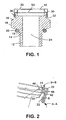
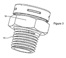
- the vent body 10 includes a root 12 having threads 14 and a head 16, which includes a hexagonal shaped portion 18.
- the hexagonal shaped portion permits using a wrench to drive the vent into a tapped housing.
- Threads may be National Pipe Thread (NPT) or straight threads. Where straight threads are used, a gasket 20 may be used to seal the vent to the housing.
- Groove 22 is cut into the head above the hexagonal portion.
- An aperture 24 extends through the vent body from root to head.
- a shell 30 is secured to the vent body by an interference fit.
- a snap ring 38 on the shell cooperates with the groove 22 to secure the shell to the vent body.
- the shell also includes a baffle 32 extending toward the cap.
- the cap 40 fits over the shell 30 and is held in place by cooperation of dimples 42 bearing on the shell.
- the cap includes perforations 44 at its outer perimeter. The perforations are positioned outside the baffle 32 such that liquids entering the perforations are prevented from contacting the membrane 50 by the baffle. Gaps between dimples provide a drainage path, labeled A-A, between the cap and the shell for liquid entering the perforations by 44. Dimples 46 in the top shell contact the upper edge of the baffle, maintaining a gap between the top shell and baffle to permit gas flow.
- the porous polymeric membrane 50 is compressed at its perimeter between the upper membrane bearing surface 48 of the shell and the lower membrane bearing surface 34 of the vent body.
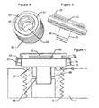
- Figs. 4-6 show another embodiment.
- the housing to be vented includes a wall 2 that has an opening or port 4 that receives an insert 60 having threads 62.
- the insert 60 has a hexagonal recess 64 adapted to receive an alien wrench type driver for installing the insert in the housing.
- Formed or machined into the insert is a passageway 66 for passing a fluid.
- a web 68 extends from the interior sides of the passageway.
- Surrounding the passageway is a groove 61 for receiving a gasket 63.
- the vent includes a shell 70 and a vent body 80.
- the vent body includes an elongated root 82 having a raised snap ring 84 formed therein.
- the shell includes perforations 72 which permit the flow of gas through the top shell.
- the shell fits over the vent body and is retained by an interference fit.
- An inward projecting snap ring 73 formed into the outer perimeter of the shell cooperates with the outer, bottom edge 86 of the vent body to hold the two pieces together.
- the porous polymeric membrane 50 is compressed at its perimeter between the upper membrane bearing surface 74 of the shell and the lower membrane bearing surface 88 of the vent body.
- the root is pressed into the insert and the snap-ring cooperates with the web within the passageway to retain the vent.
- the gasket is compressed between the wall and the vent body to form a seal between the vent and the insert.
- vent body 10 has a cylindrical root 12 for insertion into a housing.
- a locking ring 15 pressed onto the root after it is inserted into the housing holds the vent in place.
- Gasket 20 seals the vent to the housing.
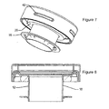
- Fig. 9 shows a two piece construction.
- a top shell is pressed over a vent body having an aperture to seal the porous polymeric membrane over the aperture.
- Fig. 10 shows a one-piece vent body construction.
- the metal vent body includes both the upper membrane bearing surface and the lower membrane bearing surface.
- Membranes suitable for use in the present invention may be tested for water-resistance using a modified Suter test apparatus, which is a low water entry pressure challenge. Water is forced against the underside of a by two circular rubber gaskets in a leak-proof clamped arrangement. In deformable samples, the sample may be overlaid by a reinforcing scrim (e.g. an open nonwoven fabric) clamped over the sample. The upper side of the sample is open to the atmosphere and visible to the operator. The water pressure on the underside of the sample is increased to 2 psi by a pump connected to a water reservoir, as indicated by a pressure gauge and regulated by an in-line valve.
- a pump connected to a water reservoir, as indicated by a pressure gauge and regulated by an in-line valve.
- the upper side of the sample is visually observed for a period of three minutes for the appearance of any water which might be forced through the sample in the event of lack of water-resistance. Liquid water seen on the surface is interpreted as a deficiency in the water-resistance of the sample (i.e., a leak). The sample has passed the test if no liquid water is visible on the upper side of the sample within the three minute test period.
- a vent body was machined from hexagonal stainless steel bar stock. The stock was cut to length and threads were cut into one end of the bar stock. A hole was drilled through the length of the bar stock to create an aperture. Starting from the end opposite from the thread, the hexagonal bar stock was rounded to create cylinder above a hexagonal driving portion. Next, a groove was cut in the cylinder near the top. Finally, the membrane bearing surface was prepared on the top of the cylinder section of the bolt by sanding with 600 grit sand paper to remove any burs and to provide some grip to the membrane bearing surface.
- the shell was formed using a deep draw metal forming process to first form a cylindrical shell.
- a horizontal "S" shape bend, as seen in the figures, was created with inside rounds of about 254 ⁇ m (0.01") to form the upper membrane bearing surface.
- inward projecting dimples were placed in four evenly spaced locations around the outer wall. The dimples are located near the bottom edge.
- the shell was perforated by drilling a series of holes near the perimeter.
- the components were assembled using a pneumatic press applying a force of 256 kg (565 pounds). Pressure was maintained for 3 seconds after the components were snapped together.
- the dimples in the top shell snap into the groove cut into the cylindrical section of the vent body. This keeps the upper membrane bearing surface pressed against a first side of an approximately 203 ⁇ m (8 mil) ePTFE membrane, while the lower membrane bearing surface of the vent body opposes the pressure. The compression of the microporous ePTFE membrane disk between the membrane bearing surfaces seals the aperture.
- a shell was formed of 304 stainless steel using a deep draw metal forming process. As described above, an "S" shaped bend was created in the shell to form the upper membrane bearing surface. Dimples were placed in four evenly spaced locations around the outer wall of the shell near the bottom edge. Perforations were provided above the "S" shaped bend.
- the vent body was also formed using a deep draw metal forming process and 304 stainless steel.
- a tube was flared to form a flange on one end.
- An inverted "U” shape having a bend radius of 254 ⁇ m (0.010") was formed such that the "U” shape was on outside edge of the flange.
- the inverted "U” shape provides the lower membrane bearing surface.
- the components were assembled with a press applying a force of 256 kg (565 pounds). This pressure is maintained for 3 seconds after the components are snapped together.
- the dimples in the shell snap over the outside edge of the "U" shape on the vent body.
- the upper membrane bearing surface in the shell is compressed against the lower membrane bearing surface on the vent body.
- the microporous membrane disk of Example 1 is compressed between bearing surfaces to form a seal surrounding the aperture.
- a silicone O-ring is placed on to the root of the vent body.
- a hole is drilled into the housing slightly larger than the outside diameter of the shaft on the vent body.
- the root on the vent body is inserted into the hole on the housing.
- a self-locking ring such as a "Rotor Clip TY-37” may be pushed onto the shaft so that the O-ring is compressed between the housing and the vent body.
- a 304 stainless steel shell was formed in the shape of an inverted cup using a deep draw metal process. A hole was cut from the center of the shell.
- a vent body was formed of the same material in the shape of an inverted cup.
- a lower membrane bearing surface was formed by an outwardly projecting rib in the top surface of the bottom cup near the outer perimeter of the vent body.
- a hole is cut in the bottom of the cup to form an aperture.
- the components were assembled using a hydraulic press applying a force of 31,8 kg (70 pounds).
- a microporous membrane disc of Example 1 was placed inside the top cup. Friction between the inner wall of the top shell and the outer wall of the vent body provides an interference fit. Compression of the microporous membrane disc between the top shell and the rib in the vent body creates a seal surrounding the aperture.
Claims (19)
- Abzug, umfassend:a) einen metallischen Körper (12) umfassend eine Öffnung (24) zum Durchfluss eines Fluids und eine erste, die Öffnung umgebende, Trägermembranoberfläche (34);b) eine poröse polymere Membran (50) mit einer ersten mit der ersten Trägermembranoberfläche (34) in Kontakt stehenden Seite; undc) eine Metallhülse (30) mit einer zweiten Trägermembranoberfläche (48), wobei die Hülse (30) durch Preßpassung am Metallkörper (12) befestigt ist;wobei die Kompression der porösen polymeren Membran (50), zwischen der ersten Trägermembranoberfläche (34) und der zweiten Trägermembranoberfläche (48), eine feuchtigkeitsfeste Dichtung bildet.
- Abzug nach Anspruch 1, ferner umfassend eine Verschlußkappe (40) zum Schützen der porösen polymeren Membran.
- Abzug nach Anspruch 2, wobei die Verschlußkappe ferner mindestens eine Perforierung (44) zum Durchfluss eines Fluids umfasst.
- Abzug nach Anspruch 1, wobei die poröse polymere Membran gasdurchlässig und Flüssigkeitsresistent ist.
- Abzug nach Anspruch 1, wobei die poröse polymere Membran ePTFE umfasst.
- Abzug nach Anspruch 5, wobei die poröse polymere Membran ePTFE und mindestens eine Trägerschicht umfasst.
- Abzug nach Anspruch 5, wobei die poröse polymere Membran ePTFE und einen Füllstoff umfasst.
- Abzug nach Anspruch 7, wobei der Füllstoff ausgewählt ist aus der Gruppe bestehend aus Absorbenzien, Adsorbenzien, Modifizierungsmitteln der Oberflächenenergie, Farbmitteln, Pigmenten, antimikrobiellen Mitteln, antibakteriellen Mitteln, Antipilzmitteln und Mischungen davon.
- Abzug nach Anspruch 5, wobei die poröse polymere Membran ferner eine Ummantelung umfasst.
- Abzug nach Anspruch 9, wobei die Ummantelung ausgewählt ist aus der Gruppe bestehend aus Absorbenzien, Adsorbenzien, Modifizierungsmitteln der Oberflächenenergie, Farbmitteln, Pigmenten, antimikrobiellen Mitteln, antibakteriellen Mitteln, Antipilzmitteln und Mischungen davon.
- Abzug nach Anspruch 1, wobei die poröse polymere Membran eine Dicke von weniger als etwa 330 µm (13 mils) hat.
- Abzug nach Anspruch 1, wobei die poröse polymere Membran eine Dicke von weniger als etwa 254 µm (10 mils) hat.
- Abzug nach Anspruch 1, wobei die poröse polymere Membran eine Dicke von weniger als etwa 127 µm (5 mils) hat.
- Abzug nach Anspruch 1, wobei die poröse polymere Membran eine Dicke von weniger als etwa 76 µm (3 mils) hat.
- Abzug nach Anspruch 1, wobei die feuchtigkeitsfeste Dichtung eine hermetische Dichtung ist.
- Abzug nach Anspruch 1, wobei der Abzugskörper rostfreien Stahl umfasst.
- Abzug nach Anspruch 1, wobei die Hülse ferner ein Baffle umfasst, das zwischen der mindestens einen Perforierung und der porösen polymeren Membran angeordnet ist, um zu verhindern, dass Flüssigkeit mit der porösen polymeren Membran in Kontakt kommt.
- Abzug nach Anspruch 17, wobei die Hülse rostfreien Stahl umfasst.
- Verfahren zum Herstellen eines Abzugs, umfassend:a) Bereitstellen eines Metallkörpers, enthaltend eine Öffnung durch denselben, zum Durchlass eines Gases;b) Verschließen der Öffnung mit einer porösen polymeren Membran, so dass die poröse polymere Membran mit dem Metallkörper in Kontakt kommt;c) Anbringen eines Metalldeckels, mit einer Perforierung darin, am Metallkörper durch eine Preßpassung, wobei die Kompression durch den Deckel der porösen polymeren Membran eine feuchtigkeitsfeste Dichtung bildet, die die Öffnung zwischen der porösen polymerischen Membran und dem Metallkörper umgibt.
Applications Claiming Priority (2)
| Application Number | Priority Date | Filing Date | Title |
|---|---|---|---|
| US10/823,066 US7357709B2 (en) | 2004-04-12 | 2004-04-12 | Metal vent |
| PCT/US2005/012294 WO2005100832A1 (en) | 2004-04-12 | 2005-04-11 | Metal vent |
Publications (2)
| Publication Number | Publication Date |
|---|---|
| EP1740861A1 EP1740861A1 (de) | 2007-01-10 |
| EP1740861B1 true EP1740861B1 (de) | 2008-11-26 |
Family
ID=34965797
Family Applications (1)
| Application Number | Title | Priority Date | Filing Date |
|---|---|---|---|
| EP05735508A Not-in-force EP1740861B1 (de) | 2004-04-12 | 2005-04-11 | Metallischer abzug |
Country Status (7)
| Country | Link |
|---|---|
| US (1) | US7357709B2 (de) |
| EP (1) | EP1740861B1 (de) |
| JP (1) | JP4718540B2 (de) |
| AT (1) | ATE415583T1 (de) |
| CA (1) | CA2562598C (de) |
| DE (1) | DE602005011268D1 (de) |
| WO (1) | WO2005100832A1 (de) |
Cited By (2)
| Publication number | Priority date | Publication date | Assignee | Title |
|---|---|---|---|---|
| EP3236722A1 (de) | 2016-04-18 | 2017-10-25 | W.L. Gore & Associates GmbH | Entlüftung |
| DE102020104039A1 (de) | 2020-02-17 | 2021-08-19 | Ifm Electronic Gmbh | Gehäuse mit Entlüftungshülse sowie Messgerät und Druckmessgerät für die Prozessmesstechnik mit einem solchen Gehäuse |
Families Citing this family (47)
| Publication number | Priority date | Publication date | Assignee | Title |
|---|---|---|---|---|
| EP2428171B1 (de) | 2001-09-24 | 2014-02-19 | Applied Medical Resources Corporation | Obturator ohne Klinge |
| JP2005525860A (ja) | 2002-05-16 | 2005-09-02 | アプライド メディカル リソーシーズ コーポレイション | 円錐状先端部をもった栓塞子 |
| GB2401330B (en) * | 2003-05-09 | 2006-04-12 | Westinghouse Brakes | Pressure equalisation device |
| EP2545860B1 (de) | 2003-10-03 | 2014-02-12 | Applied Medical Resources Corporation | Optischer Obturator ohne Klinge |
| EP1765197B1 (de) | 2004-06-29 | 2017-03-29 | Applied Medical Resources Corporation | Insufflierendes optisches operationsinstrument |
| CN100510525C (zh) * | 2004-12-07 | 2009-07-08 | 日东电工株式会社 | 通气部件及使用它的通气壳体和电子元件 |
| JP4672530B2 (ja) * | 2005-11-17 | 2011-04-20 | 日東電工株式会社 | 通気部材 |
| US8074334B2 (en) * | 2006-01-20 | 2011-12-13 | Bemis Manufacturing Company | Modular ratchet cap |
| US9845862B2 (en) * | 2006-04-17 | 2017-12-19 | W. L. Gore & Associates, Inc. | Axle vent |
| US8517977B2 (en) | 2006-10-06 | 2013-08-27 | Applied Medical Resources Corporation | Visual insufflation port |
| JP2008106825A (ja) * | 2006-10-24 | 2008-05-08 | Jtekt Corp | 密封装置 |
| SE531865C2 (sv) * | 2007-02-27 | 2009-08-25 | Scania Cv Abp | Bränsletankavluftningsanordning för en fordonsbränsletank samt en bränsletank utrustad med nämnda anordning |
| EP2837345B1 (de) | 2008-01-25 | 2016-10-05 | Applied Medical Resources Corporation | Insufflierendes Zugangssystem |
| JP5122347B2 (ja) * | 2008-04-04 | 2013-01-16 | 日東電工株式会社 | 通気部材 |
| US20100032432A1 (en) * | 2008-08-08 | 2010-02-11 | Stull Technologies, Inc. | Break-Away venting closure |
| EP2328487B1 (de) | 2008-09-29 | 2018-04-18 | Applied Medical Resources Corporation | Trokarsystem für den ersten zutritt |
| US20100154613A1 (en) * | 2008-12-19 | 2010-06-24 | Multi-Color Corporation | Label that is Removable or Having a Removable Section |
| JP5352253B2 (ja) * | 2009-01-21 | 2013-11-27 | 日東電工株式会社 | 通気部材およびその製造方法 |
| US8485214B2 (en) * | 2009-06-22 | 2013-07-16 | Eaton Corporation | Small engine emissions control valve |
| US8881931B2 (en) * | 2010-08-30 | 2014-11-11 | Avc Industrial Corp. | Waterproof and breathable plug |
| JP6066428B2 (ja) | 2011-05-02 | 2017-01-25 | アプライド メディカル リソーシーズ コーポレイション | 低輪郭の外科用万能アクセスポート |
| DE102012217030A1 (de) | 2012-09-21 | 2014-03-27 | Schaeffler Technologies Gmbh & Co. Kg | Lagerdeckel, insbesondere ABS-Sensorkappe |
| US9317068B2 (en) * | 2012-09-24 | 2016-04-19 | Donaldson Company, Inc. | Venting assembly and microporous membrane composite |
| DE102012223332B4 (de) * | 2012-12-17 | 2016-07-28 | Continental Automotive Gmbh | Druckausgleichseinrichtung und Gehäusebauteil |
| US10663192B2 (en) * | 2013-01-04 | 2020-05-26 | Fleming Vaughn Carroll | Vertical vent stack cap |
| JP2014151767A (ja) * | 2013-02-08 | 2014-08-25 | Nitto Denko Corp | 通気部材及び通気構造 |
| US20140311345A1 (en) * | 2013-04-18 | 2014-10-23 | James Peter Morrissette | Hydration container |
| US9332662B2 (en) | 2014-04-24 | 2016-05-03 | Nitto Denko Corporation | Ventilation member |
| JP5944955B2 (ja) * | 2014-07-24 | 2016-07-05 | 藤倉ゴム工業株式会社 | 通気非透水装置 |
| WO2016054409A1 (en) | 2014-10-01 | 2016-04-07 | Donaldson Company, Inc. | Tank vent with a pleated membrane |
| US20160113131A1 (en) * | 2014-10-17 | 2016-04-21 | Garmin International, Inc. | Vent assembly for an electronic device enclosure |
| KR102283424B1 (ko) * | 2015-01-15 | 2021-07-30 | 엘지이노텍 주식회사 | 자동차용 카메라 모듈 |
| EP3250306A4 (de) | 2015-01-28 | 2018-08-29 | Donaldson Company, Inc. | Entlüftungsanordnung für barriere |
| CN105546169B (zh) * | 2016-01-11 | 2017-12-01 | 唐凯 | 防水透气阀 |
| DE102016104006A1 (de) * | 2016-03-04 | 2017-09-07 | Automotive Lighting Reutlingen Gmbh | Belüftete Kraftfahrzeugbeleuchtungseinrichtung mit einem auswechselbaren Luftfilter |
| JP7034581B2 (ja) * | 2016-08-30 | 2022-03-14 | 日東電工株式会社 | 通気部材 |
| DE202017000742U1 (de) | 2017-02-10 | 2017-03-03 | Abb Schweiz Ag | Druckablassvorrichtung |
| WO2018183804A1 (en) | 2017-03-30 | 2018-10-04 | Donaldson Company, Inc. | Vent with relief valve |
| US20180299020A1 (en) * | 2017-04-18 | 2018-10-18 | Mark Shaw | Temperature Responsive Pressure Relief Filter Vent Device for Storage Drums |
| US10415688B2 (en) * | 2017-10-20 | 2019-09-17 | Valmont Industries, Inc. | Remotely mounted gearbox breather for an irrigation machine |
| CN108397581B (zh) * | 2018-05-28 | 2019-12-06 | 南京若吉电子有限公司 | 一种大尺寸加固显示器透气防潮结构 |
| USD965409S1 (en) | 2018-12-12 | 2022-10-04 | Yeti Coolers, Llc | Latch portion |
| US10766672B2 (en) | 2018-12-12 | 2020-09-08 | Yeti Coolers, Llc | Insulating container |
| WO2021028895A1 (en) * | 2019-08-10 | 2021-02-18 | Padmini Vna Mechatronics Pvt. Ltd. | Air ventilation valve |
| DE102019215742A1 (de) * | 2019-10-14 | 2021-04-15 | Elringklinger Ag | Druckausgleichsvorrichtung und Verfahren zur Herstellung einer Druckausgleichsvorrichtung |
| US11661965B2 (en) * | 2019-10-14 | 2023-05-30 | Nokia Shanghai Bell Co., Ltd. | Fastener and vent device for telecommunications equipment |
| US11850612B2 (en) * | 2020-09-15 | 2023-12-26 | Aereos Interior Solutions, LLC | Rigid bottle with pressure equalization for use in a liquid dispensing system |
Family Cites Families (37)
| Publication number | Priority date | Publication date | Assignee | Title |
|---|---|---|---|---|
| US1409902A (en) | 1921-02-07 | 1922-03-21 | Ausen Emil | Milk-can cover |
| US3962153A (en) | 1970-05-21 | 1976-06-08 | W. L. Gore & Associates, Inc. | Very highly stretched polytetrafluoroethylene and process therefor |
| SE392582B (sv) | 1970-05-21 | 1977-04-04 | Gore & Ass | Forfarande vid framstellning av ett porost material, genom expandering och streckning av en tetrafluoretenpolymer framstelld i ett pastabildande strengsprutningsforfarande |
| US4096227A (en) | 1973-07-03 | 1978-06-20 | W. L. Gore & Associates, Inc. | Process for producing filled porous PTFE products |
| DE2403244C3 (de) | 1974-01-24 | 1980-12-04 | Riedel-De Haen Ag, 3016 Seelze | Für Gase permeable, flüssigkeitsdichte Absperrvorrichtung |
| US4136796A (en) | 1974-04-11 | 1979-01-30 | Greif Bros. Corporation | Vented closure |
| US4512243A (en) * | 1980-10-03 | 1985-04-23 | Charles Bonnici | Ventilator having insert for controlling moisture and method of making same |
| US4478665A (en) | 1980-11-06 | 1984-10-23 | W. L. Gore & Associates, Inc. | Method for manufacturing highly porous, high strength PTFE articles |
| JPS6254066U (de) * | 1985-09-25 | 1987-04-03 | ||
| JPH01115082U (de) * | 1988-01-28 | 1989-08-02 | ||
| JPH01269766A (ja) | 1988-04-20 | 1989-10-27 | Suzuki Motor Co Ltd | 燃料タンクのブリーザ装置 |
| DE58905923D1 (de) * | 1988-07-21 | 1993-11-18 | Zahnradfabrik Friedrichshafen | Druckausgleicher zwischen maschinengehäuse und umgebung. |
| US4902423A (en) | 1989-02-02 | 1990-02-20 | W. L. Gore & Associates, Inc. | Highly air permeable expanded polytetrafluoroethylene membranes and process for making them |
| US5215312A (en) | 1989-09-14 | 1993-06-01 | Siemens Aktiengesellschaft | Housing with a pressure-equalizing element which is retained water-tightly around the edges within a housing wall opening |
| JP2523320Y2 (ja) * | 1989-12-15 | 1997-01-22 | エヌオーケー株式会社 | ガス抜き装置 |
| US5126054A (en) | 1990-05-24 | 1992-06-30 | Pall Corporation | Venting means |
| US5353949A (en) * | 1992-09-21 | 1994-10-11 | Pall Corporation | Vent filter assembly |
| JP2604268Y2 (ja) * | 1993-08-26 | 2000-04-24 | エヌオーケー株式会社 | ブリーザーキャップ |
| DE69412291T2 (de) | 1994-08-19 | 1998-12-03 | Gore & Ass | Ventilierte glasflasche zur gefriertrocknung und verfahren zur verminderung der kontamination von gefriergetrockneten produkten |
| US5882454A (en) | 1994-10-13 | 1999-03-16 | The Procter & Gamble Company | Process for manufacturing a venting cap |
| US5522769A (en) | 1994-11-17 | 1996-06-04 | W. L. Gore & Associates, Inc. | Gas-permeable, liquid-impermeable vent cover |
| US5928516A (en) * | 1995-01-20 | 1999-07-27 | Pall Corporation | Filter package |
| US5785390A (en) * | 1995-01-31 | 1998-07-28 | Stemco Inc. | Vented hubcap |
| US5506067A (en) * | 1995-04-04 | 1996-04-09 | Aer Energy Resources, Inc. | Rechargeable electrochemical cell and cell case therefor with vent for use in internal recombination of hydrogen and oxygen |
| US5486429A (en) | 1995-04-24 | 1996-01-23 | Aer Energy Resources, Inc. | Diffusion vent for a rechargeable metal-air cell |
| DE29514072U1 (de) | 1995-09-02 | 1995-11-02 | Geradts Gmbh | Sicherheitsstopfen für mit Gas oder Atemluft gefüllte Druckbehälter |
| US5901867A (en) | 1995-10-25 | 1999-05-11 | Roberts Polypro, Inc. | Ventable cap |
| US5596814A (en) | 1995-11-06 | 1997-01-28 | W. L. Gore & Associates, Inc. | Vented vial stopper for processing freeze-dried products |
| US6170684B1 (en) | 1996-02-26 | 2001-01-09 | Monty E. Vincent | Flask vent and method of making same |
| US5988426A (en) | 1996-11-08 | 1999-11-23 | Stern; Brett | Leakproof vented beverage lid |
| US6464425B1 (en) * | 1999-07-16 | 2002-10-15 | Robert F. Closkey | Apparatus and method for minimizing liquid infiltration into subterranean openings |
| JP4043674B2 (ja) * | 1999-11-18 | 2008-02-06 | 日東電工株式会社 | 通気キャップおよびそれを用いた屋外用ランプ,自動車用ランプならびに自動車用電装部品 |
| US6325463B1 (en) | 1999-11-23 | 2001-12-04 | Dana Corporation | Vent system for an axle and hub assembly |
| US6523724B2 (en) * | 2000-12-28 | 2003-02-25 | Unilever Home & Personal Care Usa, Division Of Conopco, Inc. | Container |
| GB2378739A (en) | 2001-08-16 | 2003-02-19 | Emhart Inc | Blind rivet having undercut flange |
| JP3746723B2 (ja) * | 2002-03-28 | 2006-02-15 | 東海興業株式会社 | 通気栓組立体 |
| JP2004011697A (ja) * | 2002-06-04 | 2004-01-15 | Shin Ei Tech:Kk | エア抜き用の栓部材 |
-
2004
- 2004-04-12 US US10/823,066 patent/US7357709B2/en not_active Expired - Lifetime
-
2005
- 2005-04-11 CA CA2562598A patent/CA2562598C/en not_active Expired - Fee Related
- 2005-04-11 DE DE602005011268T patent/DE602005011268D1/de active Active
- 2005-04-11 AT AT05735508T patent/ATE415583T1/de not_active IP Right Cessation
- 2005-04-11 EP EP05735508A patent/EP1740861B1/de not_active Not-in-force
- 2005-04-11 WO PCT/US2005/012294 patent/WO2005100832A1/en not_active Application Discontinuation
- 2005-04-11 JP JP2007508452A patent/JP4718540B2/ja not_active Expired - Fee Related
Cited By (5)
| Publication number | Priority date | Publication date | Assignee | Title |
|---|---|---|---|---|
| EP3236722A1 (de) | 2016-04-18 | 2017-10-25 | W.L. Gore & Associates GmbH | Entlüftung |
| WO2017182290A1 (en) | 2016-04-18 | 2017-10-26 | W.L. Gore & Associates Gmbh | Vent |
| KR20180130573A (ko) * | 2016-04-18 | 2018-12-07 | 더블유.엘.고어 앤드 어소시에이츠 게엠베하 | 벤트 |
| US11035398B2 (en) | 2016-04-18 | 2021-06-15 | W. L. Gore & Associates Gmbh | Vent |
| DE102020104039A1 (de) | 2020-02-17 | 2021-08-19 | Ifm Electronic Gmbh | Gehäuse mit Entlüftungshülse sowie Messgerät und Druckmessgerät für die Prozessmesstechnik mit einem solchen Gehäuse |
Also Published As
| Publication number | Publication date |
|---|---|
| JP2007532842A (ja) | 2007-11-15 |
| CA2562598A1 (en) | 2005-10-27 |
| DE602005011268D1 (de) | 2009-01-08 |
| US20050227610A1 (en) | 2005-10-13 |
| ATE415583T1 (de) | 2008-12-15 |
| US7357709B2 (en) | 2008-04-15 |
| WO2005100832A1 (en) | 2005-10-27 |
| CA2562598C (en) | 2010-02-09 |
| EP1740861A1 (de) | 2007-01-10 |
| JP4718540B2 (ja) | 2011-07-06 |
Similar Documents
| Publication | Publication Date | Title |
|---|---|---|
| EP1740861B1 (de) | Metallischer abzug | |
| JP6802288B2 (ja) | 通気口 | |
| US5914415A (en) | Vent filter member | |
| US11092253B2 (en) | Check valve | |
| EP2704542B1 (de) | Beatmungseinheit | |
| EP2704543B1 (de) | Beatmungseinheit | |
| US6524361B1 (en) | Micro-porous filter | |
| JP5336356B2 (ja) | 車軸ベント | |
| WO2012157149A1 (ja) | 通気構造 | |
| EP2733418A1 (de) | Belüftungselement | |
| KR20010049300A (ko) | 통기성 캡과, 그것을 포함하는 옥외용 램프, 자동차용램프 및 자동차용 전장 부품 | |
| CA2332512A1 (en) | Seal plate and pressure adjusting mechanism for seal plate | |
| US11077748B2 (en) | Liquid reservoir shutoff vent | |
| DE202010006041U1 (de) | Dichtring mit Membranventil | |
| JP2010062094A (ja) | 通気部材 | |
| JPH0712291Y2 (ja) | 通気弁 | |
| JP2005183753A (ja) | 圧力開放弁 |
Legal Events
| Date | Code | Title | Description |
|---|---|---|---|
| PUAI | Public reference made under article 153(3) epc to a published international application that has entered the european phase |
Free format text: ORIGINAL CODE: 0009012 |
|
| 17P | Request for examination filed |
Effective date: 20061026 |
|
| AK | Designated contracting states |
Kind code of ref document: A1 Designated state(s): AT BE BG CH CY CZ DE DK EE ES FI FR GB GR HU IE IS IT LI LT LU MC NL PL PT RO SE SI SK TR |
|
| 17Q | First examination report despatched |
Effective date: 20070219 |
|
| DAX | Request for extension of the european patent (deleted) | ||
| GRAP | Despatch of communication of intention to grant a patent |
Free format text: ORIGINAL CODE: EPIDOSNIGR1 |
|
| GRAS | Grant fee paid |
Free format text: ORIGINAL CODE: EPIDOSNIGR3 |
|
| GRAA | (expected) grant |
Free format text: ORIGINAL CODE: 0009210 |
|
| AK | Designated contracting states |
Kind code of ref document: B1 Designated state(s): AT BE BG CH CY CZ DE DK EE ES FI FR GB GR HU IE IS IT LI LT LU MC NL PL PT RO SE SI SK TR |
|
| REG | Reference to a national code |
Ref country code: GB Ref legal event code: FG4D |
|
| REG | Reference to a national code |
Ref country code: CH Ref legal event code: EP |
|
| REG | Reference to a national code |
Ref country code: IE Ref legal event code: FG4D |
|
| REF | Corresponds to: |
Ref document number: 602005011268 Country of ref document: DE Date of ref document: 20090108 Kind code of ref document: P |
|
| REG | Reference to a national code |
Ref country code: SE Ref legal event code: TRGR |
|
| PG25 | Lapsed in a contracting state [announced via postgrant information from national office to epo] |
Ref country code: ES Free format text: LAPSE BECAUSE OF FAILURE TO SUBMIT A TRANSLATION OF THE DESCRIPTION OR TO PAY THE FEE WITHIN THE PRESCRIBED TIME-LIMIT Effective date: 20090308 Ref country code: AT Free format text: LAPSE BECAUSE OF FAILURE TO SUBMIT A TRANSLATION OF THE DESCRIPTION OR TO PAY THE FEE WITHIN THE PRESCRIBED TIME-LIMIT Effective date: 20081126 Ref country code: LT Free format text: LAPSE BECAUSE OF FAILURE TO SUBMIT A TRANSLATION OF THE DESCRIPTION OR TO PAY THE FEE WITHIN THE PRESCRIBED TIME-LIMIT Effective date: 20081126 |
|
| NLV1 | Nl: lapsed or annulled due to failure to fulfill the requirements of art. 29p and 29m of the patents act | ||
| PG25 | Lapsed in a contracting state [announced via postgrant information from national office to epo] |
Ref country code: FI Free format text: LAPSE BECAUSE OF FAILURE TO SUBMIT A TRANSLATION OF THE DESCRIPTION OR TO PAY THE FEE WITHIN THE PRESCRIBED TIME-LIMIT Effective date: 20081126 Ref country code: NL Free format text: LAPSE BECAUSE OF FAILURE TO SUBMIT A TRANSLATION OF THE DESCRIPTION OR TO PAY THE FEE WITHIN THE PRESCRIBED TIME-LIMIT Effective date: 20081126 Ref country code: PL Free format text: LAPSE BECAUSE OF FAILURE TO SUBMIT A TRANSLATION OF THE DESCRIPTION OR TO PAY THE FEE WITHIN THE PRESCRIBED TIME-LIMIT Effective date: 20081126 Ref country code: IS Free format text: LAPSE BECAUSE OF FAILURE TO SUBMIT A TRANSLATION OF THE DESCRIPTION OR TO PAY THE FEE WITHIN THE PRESCRIBED TIME-LIMIT Effective date: 20090326 Ref country code: SI Free format text: LAPSE BECAUSE OF FAILURE TO SUBMIT A TRANSLATION OF THE DESCRIPTION OR TO PAY THE FEE WITHIN THE PRESCRIBED TIME-LIMIT Effective date: 20081126 |
|
| PG25 | Lapsed in a contracting state [announced via postgrant information from national office to epo] |
Ref country code: RO Free format text: LAPSE BECAUSE OF FAILURE TO SUBMIT A TRANSLATION OF THE DESCRIPTION OR TO PAY THE FEE WITHIN THE PRESCRIBED TIME-LIMIT Effective date: 20081126 Ref country code: BE Free format text: LAPSE BECAUSE OF FAILURE TO SUBMIT A TRANSLATION OF THE DESCRIPTION OR TO PAY THE FEE WITHIN THE PRESCRIBED TIME-LIMIT Effective date: 20081126 Ref country code: DK Free format text: LAPSE BECAUSE OF FAILURE TO SUBMIT A TRANSLATION OF THE DESCRIPTION OR TO PAY THE FEE WITHIN THE PRESCRIBED TIME-LIMIT Effective date: 20081126 Ref country code: BG Free format text: LAPSE BECAUSE OF FAILURE TO SUBMIT A TRANSLATION OF THE DESCRIPTION OR TO PAY THE FEE WITHIN THE PRESCRIBED TIME-LIMIT Effective date: 20090226 Ref country code: EE Free format text: LAPSE BECAUSE OF FAILURE TO SUBMIT A TRANSLATION OF THE DESCRIPTION OR TO PAY THE FEE WITHIN THE PRESCRIBED TIME-LIMIT Effective date: 20081126 |
|
| PG25 | Lapsed in a contracting state [announced via postgrant information from national office to epo] |
Ref country code: PT Free format text: LAPSE BECAUSE OF FAILURE TO SUBMIT A TRANSLATION OF THE DESCRIPTION OR TO PAY THE FEE WITHIN THE PRESCRIBED TIME-LIMIT Effective date: 20090427 Ref country code: CZ Free format text: LAPSE BECAUSE OF FAILURE TO SUBMIT A TRANSLATION OF THE DESCRIPTION OR TO PAY THE FEE WITHIN THE PRESCRIBED TIME-LIMIT Effective date: 20081126 |
|
| PG25 | Lapsed in a contracting state [announced via postgrant information from national office to epo] |
Ref country code: SK Free format text: LAPSE BECAUSE OF FAILURE TO SUBMIT A TRANSLATION OF THE DESCRIPTION OR TO PAY THE FEE WITHIN THE PRESCRIBED TIME-LIMIT Effective date: 20081126 |
|
| PLBE | No opposition filed within time limit |
Free format text: ORIGINAL CODE: 0009261 |
|
| STAA | Information on the status of an ep patent application or granted ep patent |
Free format text: STATUS: NO OPPOSITION FILED WITHIN TIME LIMIT |
|
| 26N | No opposition filed |
Effective date: 20090827 |
|
| REG | Reference to a national code |
Ref country code: CH Ref legal event code: PL |
|
| PG25 | Lapsed in a contracting state [announced via postgrant information from national office to epo] |
Ref country code: CH Free format text: LAPSE BECAUSE OF NON-PAYMENT OF DUE FEES Effective date: 20090430 Ref country code: LI Free format text: LAPSE BECAUSE OF NON-PAYMENT OF DUE FEES Effective date: 20090430 |
|
| REG | Reference to a national code |
Ref country code: IE Ref legal event code: MM4A |
|
| PG25 | Lapsed in a contracting state [announced via postgrant information from national office to epo] |
Ref country code: MC Free format text: LAPSE BECAUSE OF NON-PAYMENT OF DUE FEES Effective date: 20090430 Ref country code: IE Free format text: LAPSE BECAUSE OF NON-PAYMENT OF DUE FEES Effective date: 20090411 |
|
| PG25 | Lapsed in a contracting state [announced via postgrant information from national office to epo] |
Ref country code: GR Free format text: LAPSE BECAUSE OF FAILURE TO SUBMIT A TRANSLATION OF THE DESCRIPTION OR TO PAY THE FEE WITHIN THE PRESCRIBED TIME-LIMIT Effective date: 20090227 |
|
| PG25 | Lapsed in a contracting state [announced via postgrant information from national office to epo] |
Ref country code: LU Free format text: LAPSE BECAUSE OF NON-PAYMENT OF DUE FEES Effective date: 20090411 |
|
| PG25 | Lapsed in a contracting state [announced via postgrant information from national office to epo] |
Ref country code: HU Free format text: LAPSE BECAUSE OF FAILURE TO SUBMIT A TRANSLATION OF THE DESCRIPTION OR TO PAY THE FEE WITHIN THE PRESCRIBED TIME-LIMIT Effective date: 20090527 |
|
| PG25 | Lapsed in a contracting state [announced via postgrant information from national office to epo] |
Ref country code: TR Free format text: LAPSE BECAUSE OF FAILURE TO SUBMIT A TRANSLATION OF THE DESCRIPTION OR TO PAY THE FEE WITHIN THE PRESCRIBED TIME-LIMIT Effective date: 20081126 |
|
| PG25 | Lapsed in a contracting state [announced via postgrant information from national office to epo] |
Ref country code: CY Free format text: LAPSE BECAUSE OF FAILURE TO SUBMIT A TRANSLATION OF THE DESCRIPTION OR TO PAY THE FEE WITHIN THE PRESCRIBED TIME-LIMIT Effective date: 20081126 |
|
| REG | Reference to a national code |
Ref country code: GB Ref legal event code: 732E Free format text: REGISTERED BETWEEN 20150723 AND 20150729 |
|
| REG | Reference to a national code |
Ref country code: DE Ref legal event code: R082 Ref document number: 602005011268 Country of ref document: DE Representative=s name: MARKS & CLERK (LUXEMBOURG) LLP, LU Ref country code: DE Ref legal event code: R081 Ref document number: 602005011268 Country of ref document: DE Owner name: W.L. GORE & ASSOCIATES, INC., NEWARK, US Free format text: FORMER OWNER: GORE ENTERPRISE HOLDINGS, INC., NEWARK, DEL., US |
|
| REG | Reference to a national code |
Ref country code: FR Ref legal event code: PLFP Year of fee payment: 12 |
|
| REG | Reference to a national code |
Ref country code: FR Ref legal event code: TP Owner name: W.L. GORE & ASSOCIATES, INC., US Effective date: 20160510 |
|
| REG | Reference to a national code |
Ref country code: FR Ref legal event code: PLFP Year of fee payment: 13 |
|
| PGFP | Annual fee paid to national office [announced via postgrant information from national office to epo] |
Ref country code: SE Payment date: 20170324 Year of fee payment: 13 Ref country code: FR Payment date: 20170322 Year of fee payment: 13 |
|
| PGFP | Annual fee paid to national office [announced via postgrant information from national office to epo] |
Ref country code: IT Payment date: 20170322 Year of fee payment: 13 |
|
| REG | Reference to a national code |
Ref country code: SE Ref legal event code: EUG |
|
| PG25 | Lapsed in a contracting state [announced via postgrant information from national office to epo] |
Ref country code: SE Free format text: LAPSE BECAUSE OF NON-PAYMENT OF DUE FEES Effective date: 20180412 |
|
| PG25 | Lapsed in a contracting state [announced via postgrant information from national office to epo] |
Ref country code: FR Free format text: LAPSE BECAUSE OF NON-PAYMENT OF DUE FEES Effective date: 20180430 Ref country code: IT Free format text: LAPSE BECAUSE OF NON-PAYMENT OF DUE FEES Effective date: 20180411 |
|
| PGFP | Annual fee paid to national office [announced via postgrant information from national office to epo] |
Ref country code: GB Payment date: 20210324 Year of fee payment: 17 |
|
| PGFP | Annual fee paid to national office [announced via postgrant information from national office to epo] |
Ref country code: DE Payment date: 20210323 Year of fee payment: 17 |
|
| REG | Reference to a national code |
Ref country code: DE Ref legal event code: R119 Ref document number: 602005011268 Country of ref document: DE |
|
| GBPC | Gb: european patent ceased through non-payment of renewal fee |
Effective date: 20220411 |
|
| PG25 | Lapsed in a contracting state [announced via postgrant information from national office to epo] |
Ref country code: GB Free format text: LAPSE BECAUSE OF NON-PAYMENT OF DUE FEES Effective date: 20220411 Ref country code: DE Free format text: LAPSE BECAUSE OF NON-PAYMENT OF DUE FEES Effective date: 20221103 |