EP1739264A2 - Ventil für einen Antrieb eines Flügels einer Tür oder eines Fensters - Google Patents
Ventil für einen Antrieb eines Flügels einer Tür oder eines Fensters Download PDFInfo
- Publication number
- EP1739264A2 EP1739264A2 EP06116038A EP06116038A EP1739264A2 EP 1739264 A2 EP1739264 A2 EP 1739264A2 EP 06116038 A EP06116038 A EP 06116038A EP 06116038 A EP06116038 A EP 06116038A EP 1739264 A2 EP1739264 A2 EP 1739264A2
- Authority
- EP
- European Patent Office
- Prior art keywords
- valve
- valve body
- hydraulic
- control device
- valves
- Prior art date
- Legal status (The legal status is an assumption and is not a legal conclusion. Google has not performed a legal analysis and makes no representation as to the accuracy of the status listed.)
- Granted
Links
Images
Classifications
-
- E—FIXED CONSTRUCTIONS
- E05—LOCKS; KEYS; WINDOW OR DOOR FITTINGS; SAFES
- E05F—DEVICES FOR MOVING WINGS INTO OPEN OR CLOSED POSITION; CHECKS FOR WINGS; WING FITTINGS NOT OTHERWISE PROVIDED FOR, CONCERNED WITH THE FUNCTIONING OF THE WING
- E05F3/00—Closers or openers with braking devices, e.g. checks; Construction of pneumatic or liquid braking devices
- E05F3/04—Closers or openers with braking devices, e.g. checks; Construction of pneumatic or liquid braking devices with liquid piston brakes
- E05F3/12—Special devices controlling the circulation of the liquid, e.g. valve arrangement
-
- E—FIXED CONSTRUCTIONS
- E05—LOCKS; KEYS; WINDOW OR DOOR FITTINGS; SAFES
- E05Y—INDEXING SCHEME ASSOCIATED WITH SUBCLASSES E05D AND E05F, RELATING TO CONSTRUCTION ELEMENTS, ELECTRIC CONTROL, POWER SUPPLY, POWER SIGNAL OR TRANSMISSION, USER INTERFACES, MOUNTING OR COUPLING, DETAILS, ACCESSORIES, AUXILIARY OPERATIONS NOT OTHERWISE PROVIDED FOR, APPLICATION THEREOF
- E05Y2201/00—Constructional elements; Accessories therefor
- E05Y2201/20—Brakes; Disengaging means; Holders; Stops; Valves; Accessories therefor
-
- E—FIXED CONSTRUCTIONS
- E05—LOCKS; KEYS; WINDOW OR DOOR FITTINGS; SAFES
- E05Y—INDEXING SCHEME ASSOCIATED WITH SUBCLASSES E05D AND E05F, RELATING TO CONSTRUCTION ELEMENTS, ELECTRIC CONTROL, POWER SUPPLY, POWER SIGNAL OR TRANSMISSION, USER INTERFACES, MOUNTING OR COUPLING, DETAILS, ACCESSORIES, AUXILIARY OPERATIONS NOT OTHERWISE PROVIDED FOR, APPLICATION THEREOF
- E05Y2201/00—Constructional elements; Accessories therefor
- E05Y2201/20—Brakes; Disengaging means; Holders; Stops; Valves; Accessories therefor
- E05Y2201/252—Type of friction
- E05Y2201/254—Fluid or viscous friction
-
- E—FIXED CONSTRUCTIONS
- E05—LOCKS; KEYS; WINDOW OR DOOR FITTINGS; SAFES
- E05Y—INDEXING SCHEME ASSOCIATED WITH SUBCLASSES E05D AND E05F, RELATING TO CONSTRUCTION ELEMENTS, ELECTRIC CONTROL, POWER SUPPLY, POWER SIGNAL OR TRANSMISSION, USER INTERFACES, MOUNTING OR COUPLING, DETAILS, ACCESSORIES, AUXILIARY OPERATIONS NOT OTHERWISE PROVIDED FOR, APPLICATION THEREOF
- E05Y2900/00—Application of doors, windows, wings or fittings thereof
- E05Y2900/10—Application of doors, windows, wings or fittings thereof for buildings or parts thereof
- E05Y2900/13—Type of wing
- E05Y2900/132—Doors
Definitions
- the invention relates to a valve for a drive of a wing of a door or a window according to the preamble of claim 1.
- a drive for the wing of a door with a housing and filled with a hydraulic fluid receiving space.
- the drive has in the receiving space a displaceable against the force of a spring arranged piston, which cooperates with an output shaft for wing actuation.
- In the drive housing further bores are arranged, which allow an overflow of the hydraulic fluid from one piston side to the other.
- a valve for throttling the flow velocity in the closing and in the opening direction is arranged in these hydraulic channels.
- the GB 2 193 757 A discloses a door closer, with a piston which is displaceably guided in a piston chamber filled with a hydraulic fluid, and with a further space in which a compressible air bag is located as energy storage.
- the piston chamber and the other space are connected by hydraulic channels, in which valves are arranged to control the door closer.
- valves require multiple holes, and a larger housing is required for space.
- the invention has for its object to produce a cost-effective valve assembly.
- a hydraulic door operator has a piston, which is arranged in a housing and acted upon by a spring, which cooperates with a shaft on which a lever for actuating a door is arranged.
- the lever When opening the door, the lever is actuated, and stretched over the shaft and the piston, the spring applied to the piston.
- an electro-hydraulic actuator may be provided to allow a motorized opening of the wing.
- the hydraulic fluid in the housing must flow over the hydraulic channels and valves from one side of the piston to the other as the piston chambers on both sides of the piston change as a result of its displacement. In this case, the slightest possible overflow of the hydraulic fluid is made possible when opening the door in order to achieve an unrestrained operation of the door.
- two valves are arranged so that a second valve is located in a first valve.
- a valve seat is formed, which is associated with the first valve.
- the hydraulic fluid can flow from one hydraulic channel into another hydraulic channel.
- sealing elements are arranged on the valve body, which seal the valve to the outside against the housing and against not the valve associated hydraulic channels.
- the valve body is arranged in a bore in the housing, in which a thread is introduced, whereby the valve passage can be adjusted by turning with a tool.
- the second valve is arranged to save space in the first valve.
- a thread is present in the valve body of the first valve, in which the valve body of the second valve is adjustably received.
- a seal is arranged, which seals the valve body to the outside against the valve body of the first valve.
- a valve seat is formed, which cooperates with the valve body of the second valve.
- the first valve has recesses, through which hydraulic fluid passes to the second valve, and can flow over the valve seat.
- the valves may each have a passageway that allows a forced flow when the valve is closed, so that the respective function of the drive is not completely blocked.
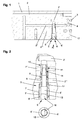
- FIG. 1 shows a detail of a housing 1 of a door drive in a sectional illustration.
- hydraulic channels 2, 2 ', 2 ", 2'” are arranged, which allow an overflow of hydraulic fluid.
- the overflow can be regulated to control the door drive by valves 5, 6 arranged in the hydraulic passages 2, 2 ', 2 ", 2'".
- a connection 17 for connecting a hydraulic pump can be present on the hydraulic channel 2 '.
- the hydraulic channels 2, 2 ', 2 ", 2'” are introduced from the outside into the housing 1 and sealed, for example, with balls 3 as closure elements. Holes 4 can be arranged between the hydraulic channels 2, 2', 2" with one another and with the piston chambers.
- hydraulic fluid flows to the outer valve 5 via the hydraulic passage 2 ", wherein a valve seat 10 assigned to the valve 5 is formed in the housing 1.
- a valve seat 10 assigned to the valve 5 is formed in the housing 1.
- the hydraulic fluid can flow off into the hydraulic channel 2 'on the valve body 5', whereby a passage 11 can be arranged which allows a forced flow when the valve 5 is closed, so that the drive is not completely blocked when there is a counterforce on the wing.
- valve body 5 'sealing elements 9, 9' are arranged, which seal the valve 5 against the housing 1.
- the sealing element 9 seals the hydraulic channels 2 "and 2 '" against each other.
- the sealing element 9 'seals the hydraulic channel 2'"outwards, the valve body 5 'being in a bore in the housing 1 arranged, in which a thread 7 is introduced.
- the valve 6 is arranged to save space in the valve 5.
- a thread 12 is present in the valve body 5 ', in which the valve body 6' is adjustably received.
- the valve 6 in the valve body 6 ' also, for example, a slot 16 for engagement of a tool.
- a valve seat 14 is formed, which cooperates with the valve body 6' and forms the valve 6.
- the valve body 5 ' has recesses 8 through which hydraulic fluid can flow from the hydraulic channel 2' "to the valve 6 and can flow over into the channel 2 'via the valve seat 14.
- valve body 6 It is likewise possible to form a flow channel 11 on the valve body 6', which allows an overflow of hydraulic fluid even when the valve 6 is completely closed, and the flow passage 11 can also be formed on the valve seat 14 of the valve body 5.
- the valve 6 has on the valve body 6 'a sealing element 13 which seals the valve 6 to the outside.
- the thread 7, in which the valve body 5 'is rotatably arranged can have a smaller pitch than the thread 12 in which the valve body 6 'of the valve 6 is arranged.
- the larger passage cross section of the outer valve 5 can be compensated.
- valve body 5 By the use of two sealing elements 9, 9 'on the valve body 5' and a sealing element 13 on the valve body 6 ', it is achieved that the valve 5 is not adjusted in an adjustment operation of the valve 6. Likewise, that with an adjustment of the valve 5, the valve body 6 'rotates in the valve body 5', so that the valve body 6 'remains unchanged in its position in the valve body 5'.
- the adjustability of the valves can also be influenced. This is the adjustability the adjustment of the respective other valve 6, 5.
- the setting can also be achieved or supported by different pitches of the thread 7, 12.
Landscapes
- Power-Operated Mechanisms For Wings (AREA)
- Lift Valve (AREA)
- Check Valves (AREA)
- Closing And Opening Devices For Wings, And Checks For Wings (AREA)
Abstract
Description
- Die Erfindung betrifft ein Ventil für einen Antrieb eines Flügels einer Tür oder eines Fensters nach dem Oberbegriff des Anspruchs 1.
- Aus der
DE 32 03 390 C2 ist ein Antrieb für den Flügel einer Tür bekannt, mit einem Gehäuse und einem mit einer Hydraulikflüssigkeit gefüllten Aufnahmeraum. Der Antrieb weist im Aufnahmeraum einen gegen die Kraft einer Feder verschiebbar angeordneten Kolben auf, der mit einer Abtriebswelle zur Flügelbetätigung zusammenwirkt. Im Antriebsgehäuse sind weiterhin Bohrungen angeordnet, welche ein Überströmen der Hydraulikflüssigkeit von einer Kolbenseite zur anderen ermöglichen. Zur Steuerung der Flügelbewegung ist in diesen Hydraulikkanälen jeweils ein Ventil zur Drosselung der Fließgeschwindigkeit in Schließ- und in Öffnungsrichtung angeordnet. - Die
GB 2 193 757 A - Durch die Verwendung von zwei Ventilen sind mehrere Bohrungen herzustellen, und aus Platzgründen ist ein größeres Gehäuse erforderlich.
- Der Erfindung liegt die Aufgabe zugrunde, eine kostengünstige Ventilanordnung herzustellen.
- Die Aufgabe wird durch die Merkmale des Anspruchs 1 gelöst.
- Die Unteransprüche bilden vorteilhafte Ausgestaltungsmöglichkeiten der Erfindung.
- Ein hydraulischer Türantrieb weist einen in einem Gehäuse angeordneten, mit einer Feder beaufschlagten Kolben auf, welcher mit einer Welle zusammenwirkt, an der ein Hebel zum Betätigen einer Tür angeordnet ist. Beim Öffnen der Tür wird der Hebel betätigt, und über die Welle und den Kolben die am Kolben anliegende Feder gespannt. Alternativ kann auch z. B. eine elektrohydraulische Betätigung vorgesehen sein, um ein motorisches Öffnen des Flügels zu ermöglichen. Die im Gehäuse befindliche Hydraulikflüssigkeit muss über Hydraulikkanäle und Ventile von einer Kolbenseite auf die andere überströmen, da sich die Kolbenräume beiderseits des Kolbens durch dessen Verschiebung verändern. Dabei wird beim Öffnen der Tür ein möglichst leichtes Überströmen der Hydraulikflüssigkeit ermöglicht, um ein ungebremstes Betätigen der Tür zu erzielen. Beim selbsttätigen Schließen der Tür, durch das Entspannen der beim Öffnen gespannten Feder, wird der Kolben wieder in seine Ausgangslage zurückgeführt, wobei die Hydraulikflüssigkeit wiederum überströmen muss. Durch die Anordnung von Hydraulikkanälen mit Ventilen kann der Schließvorgang gebremst erfolgen, wobei mehrere Phasen des Schließvorgangs mit unterschiedlichen Schließgeschwindigkeiten möglich sind.
- Erfindungsgemäß werden, um kostengünstige, möglichst wenige und kurze Hydraulikkanäle im Gehäuse des Türantriebs auszubilden, zwei Ventile so angeordnet, dass sich ein zweites Ventil in einem ersten Ventil befindet.
- Im Gehäuse ist dabei ein Ventilsitz ausgebildet, welcher dem ersten Ventil zugeordnet ist. Durch einen zwischen einem Ventilkörper des Ventils und dem Ventilsitz bestehenden Spalt kann die Hydraulikflüssigkeit von einem Hydraulikkanal in einen anderen Hydraulikkanal strömen.
- Weiterhin sind am Ventilkörper Dichtelemente angeordnet, welche das Ventil nach außen hin gegen das Gehäuse und gegen nicht dem Ventil zugeordneten Hydraulikkanälen abdichten. Der Ventilkörper ist in einer Bohrung im Gehäuse angeordnet, in welche ein Gewinde eingebracht ist, wodurch der Ventildurchlass durch Drehen mit einem Werkzeug verstellt werden kann.
- Das zweite Ventil ist platzsparend im ersten Ventil angeordnet. Dazu ist im Ventilkörper des ersten Ventils ein Gewinde vorhanden, in welchem der Ventilkörper des zweite Ventils verstellbar aufgenommen ist. Am zweiten Ventilkörper ist eine Dichtung angeordnet, die den Ventilkörper nach außen hin gegen den Ventilkörper des ersten Ventils abgedichtet. Im ersten Ventil ist ein Ventilsitz ausgebildet, welcher mit dem Ventilkörper des zweiten Ventils zusammenwirkt. Das erste Ventil weist Aussparungen auf, durch welche Hydraulikflüssigkeit zum zweiten Ventil gelangt, und über dessen Ventilsitz überströmen kann. Die Ventile können jeweils einen Durchlasskanal aufweisen, der bei geschlossenem Ventil einen Zwangsdurchfluss ermöglicht, damit die jeweilige Funktion des Antriebs nicht vollständig blockiert wird.
- Durch verschiedene Steigungen der Gewinde, in welchem die jeweiligen Ventilkörper der Ventile aufgenommen sind, wird erreicht, dass sich bei gleicher Verstellung - beispielsweise um eine Umdrehung - der Durchlassquerschnitt beider Ventile gleich verändert. Damit wird der größere Durchlassquerschnitt des ersten, äußeren Ventils ausgeglichen.
- Durch die Verwendung zweier Dichtelemente am ersten Ventil und nur eines Dichtelements am zweiten Ventil wird erreicht, dass sich das erste Ventil, aufgrund der unterschiedlichen Haftreibung bei einer Verstellbetätigung des zweiten Ventils, nicht mitverstellt. Ebenso bleibt der Ventilkörper des zweiten Ventils in seiner Lage im ersten Ventil unverändert, wenn das erste Ventil verstellt wird. Durch die Wahl unterschiedlicher Werkstoffe für die Dichtelemente kann diese Einstellbarkeit der Ventile beeinflusst werden. Auch durch die unterschiedliche Steigungen der Gewinde, in welchen die Ventilkörper aufgenommen sind, kann die Wirkung verändert werden.
- Im Nachfolgenden wird ein Ausführungsbeispiel in der Zeichnung anhand der Figuren näher erläutert.
- Dabei zeigen:
- Fig. 1
- einen Ausschnitt eines Schnitts durch das Gehäuse eines Türantriebs mit einem erfindungsgemäßen Ventil;
- Fig. 2
- das Ventil gemäß Fig. 1 in vergrößerter Darstellung mit einer Ansicht auf das Ventil gemäß Pfeil A in Fig. 1.
- In der Fig. 1 ist ein Ausschnitt eines Gehäuses 1 eines Türantriebs in geschnittener Darstellung gezeigt. Im Gehäuse 1 sind Hydraulikkanäle 2, 2', 2", 2'" angeordnet, welche ein Überströmen von Hydraulikflüssigkeit ermöglichen. Das Überströmen kann zur Steuerung des Türantriebs durch in den Hydraulikkanälen 2, 2', 2", 2'" angeordnete Ventile 5, 6 reguliert werden. Am Hydraulikkanal 2' kann dabei ein Anschluss 17 zum Anschluss einer Hydraulikpumpe vorhanden sein. Um kostengünstig möglichst wenige und kurze Hydraulikkanäle 2, 2', 2", 2'" ausbilden zu können, werden die Ventile 5, 6 erfindungsgemäß so angeordnet, dass sich das ein Ventilkörper 6' des zweiten Ventils 6 in einem Ventilkörper 5' des ersten Ventils 5 befindet. Die Hydraulikkanäle 2, 2', 2" werden in das Gehäuse 1 von außen eingebracht und beispielsweise mit Kugeln 3 als Verschlusselemente abgedichtet. Zwischen den Hydraulikkanälen 2, 2', 2" untereinander und zu den Kolbenräumen hin können Bohrungen 4 angeordnet sein.
- Wie es in der Fig. 2 vergrößert dargestellt ist, strömt dem äußeren Ventil 5 über den Hydraulikkanal 2" Hydraulikflüssigkeit zu. Im Gehäuse 1 ist dabei ein dem Ventil 5 zugeordneter Ventilsitz 10 ausgebildet. Durch den zwischen dem Ventilkörper 5' und dem Ventilsitz 10 bestehenden Spalt kann die Hydraulikflüssigkeit in den Hydraulikkanal 2' abströmen. Am Ventilkörper 5' kann ein Durchlasskanal 11 angeordnet sein, der bei geschlossenem Ventil 5 einen Zwangsdurchfluss ermöglicht, damit der Antrieb bei einer Gegenkraft auf den Flügel nicht vollständig blockiert wird.
- Am Ventilkörper 5' sind Dichtelemente 9, 9' angeordnet, welche das Ventil 5 gegen das Gehäuse 1 abdichten. Dabei dichtet das Dichtelement 9 die Hydraulikkanäle 2" und 2'" gegeneinander ab. Das Dichtelement 9' dichtet den Hydraulikkanal 2'" nach außen hin ab. Der Ventilkörper 5' ist in einer Bohrung im Gehäuse 1 angeordnet, in welche ein Gewinde 7 eingebracht ist. Durch Verdrehen des Ventilkörpers 5' - durch den Eingriff mit einem Werkzeug in einen Schlitz 15 - ist die Lage des Ventilkörpers 5' in Richtung auf den im Gehäuse 1 ausgebildeten Ventilsitz 10 veränderbar.
- Das Ventil 6 ist platzsparend im Ventil 5 angeordnet. Dazu ist im Ventilkörper 5' ein Gewinde 12 vorhanden, in welchem der Ventilkörper 6' verstellbar aufgenommen ist. Zur Verstellung weist das Ventil 6 im Ventilkörper 6' ebenfalls beispielsweise einen Schlitz 16 zum Eingriff eines Werkzeuges auf. Im Ventilkörper 5' ist ein Ventilsitz 14 ausgebildet, welcher mit dem Ventilkörper 6' zusammenwirkt und das Ventil 6 bildet. Der Ventilkörper 5' weist Aussparungen 8 auf, durch welche Hydraulikflüssigkeit aus dem Hydraulikkanal 2'" zum Ventil 6 gelangt, und über den Ventilsitz 14 in den Kanal 2' überströmen kann. Es ist ebenfalls möglich, am Ventilkörper 6' einen Durchflusskanal 11 auszubilden, welcher auch bei vollständig geschlossenem Ventil 6 ein Überströmen von Hydraulikflüssigkeit ermöglicht. Der Durchflusskanal 11 kann auch am Ventilsitz 14 des Ventilkörpers 5' ausgebildet sein. Das Ventil 6 weist am Ventilkörper 6' ein Dichtelement 13 auf, welches das Ventil 6 nach außen hin abdichtet.
- Um bei beiden Ventilen 5, 6 bei gleicher Verstellung, beispielsweise um eine Umdrehung, die gleiche Veränderung im Durchlassquerschnitt für die Hydraulikflüssigkeit zu erzielen, kann das Gewinde 7, in welchem der Ventilkörper 5' drehbar angeordnet ist, eine geringere Steigung aufweisen als das Gewinde 12, in welchem der Ventilkörper 6' des Ventils 6 angeordnet ist. Dadurch kann der größere Durchlassquerschnitt des äußeren Ventils 5 kompensiert werden.
- Durch die Verwendung zweier Dichtelemente 9, 9' am Ventilkörper 5' und eines Dichtelements 13 am Ventilkörper 6', wird erreicht, dass sich das Ventil 5 bei einer Verstellbetätigung des Ventils 6 nicht mitverstellt. Ebenso, dass sich bei einem Verstellen des Ventils 5 der Ventilkörper 6' im Ventilkörper 5' mitdreht, so dass der Ventilkörper 6' in seiner Lage im Ventilkörper 5' unverändert bleibt. Durch die Wahl unterschiedlicher Werkstoffe für die Dichtelemente 9, 9', 13 kann die Einstellbarkeit der Ventile ebenfalls beeinflusst werden. Damit ist die Verstellbarkeit der Ventile 5, 6 unabhängig von der Verstellung des jeweils anderen Ventils 6, 5. Die Einstellung kann auch durch unterschiedliche Steigungen der Gewinde 7, 12 erreicht bzw. unterstützt werden.
-
- 1
- Gehäuse
- 2 bis 2'"
- Hydraulikkanäle
- 3
- Verschlusselement
- 4
- Bohrung
- 5
- Ventil
- 5'
- Ventilkörper
- 6
- Ventil
- 6'
- Ventilkörper
- 7
- Gewinde
- 8
- Aussparung
- 9, 9'
- Dichtelement
- 10
- Ventilsitz
- 11
- Durchlasskanal
- 12
- Gewinde
- 13
- Dichtelement
- 14
- Ventilsitz
- 15
- Schlitz
- 16
- Schlitz
- 17
- Anschluss
Claims (9)
- Steuerungsvorrichtung für einen hydraulischen Türantrieb mit mindestens zwei Ventilen, mit Hydraulikkanälen, durch welche die Hydraulikflüssigkeit des Türantriebs strömen kann, und in welchen die Ventile regulierend angeordnet sind,
dadurch gekennzeichnet,
dass ein Ventilkörper (6') des zweiten Ventils (6) in einem Ventilkörper (5') des ersten Ventils (5) angeordnet ist. - Steuerungsvorrichtung nach Anspruch 1,
dadurch gekennzeichnet , dass der Ventilsitz (14) des Ventils (6) im Ventilkörper (5') ausgebildet ist. - Steuerungsvorrichtung nach Anspruch 1,
dadurch gekennzeichnet , dass der Ventilkörper (5') Aussparungen (8) aufweist, durch welche der Hydraulikkanal (2"') mit dem Ventil (6) verbunden ist. - Steuerungsvorrichtung nach Anspruch 1,
dadurch gekennzeichnet, dass am Ventilkörper (5') ein Dichtelement (9) angeordnet ist, zur Abdichtung des dem Ventil (5) zugeordneten Hydraulikkanals (2") gegenüber dem, dem Ventil (6) zugeordneten Hydraulikkanal (2'''). - Steuerungsvorrichtung nach Anspruch 1,
dadurch gekennzeichnet , dass der Ventilsitz (10) des Ventils (5) im Gehäuse (1) ausgebildet ist. - Steuerungsvorrichtung nach Anspruch 1,
dadurch gekennzeichnet , dass mindestens eines der Ventile (5, 6) am Ventilkörper (5', 6') einen Durchlasskanal (11) aufweist, durch welchen ein minimaler Durchfluss von Hydraulikflüssigkeit bestimmt wird. - Steuerungsvorrichtung nach Anspruch 1,
dadurch gekennzeichnet , dass das Ventil (6) am Ventilkörper (6') ein Dichtelement (13) zur Abdichtung gegen den Ventilkörper (5') des Ventils (5) aufweist. - Steuerungsvorrichtung nach Anspruch 7,
dadurch gekennzeichnet, dass beim Verstellen des Ventils (5) das Ventil (6) durch das Dichtelement (13) mitbewegt wird, wodurch die Lage des Ventilkörpers (6') innerhalb des Ventilkörpers (5') unverändert bleibt. - Steuerungsvorrichtung nach Anspruch 1,
dadurch gekennzeichnet, dass beim Verstellen des Ventils (6) der Ventilkörper (5') durch die Dichtelemente (9, 9') in seiner Lage im Gehäuse (1) unverändert bleibt.
Applications Claiming Priority (1)
| Application Number | Priority Date | Filing Date | Title |
|---|---|---|---|
| DE102005030756A DE102005030756B4 (de) | 2005-06-29 | 2005-06-29 | Ventil für einen Antrieb eines Flügels einer Tür oder eines Fensters |
Publications (3)
| Publication Number | Publication Date |
|---|---|
| EP1739264A2 true EP1739264A2 (de) | 2007-01-03 |
| EP1739264A3 EP1739264A3 (de) | 2008-12-10 |
| EP1739264B1 EP1739264B1 (de) | 2010-01-20 |
Family
ID=37074629
Family Applications (1)
| Application Number | Title | Priority Date | Filing Date |
|---|---|---|---|
| EP06116038A Active EP1739264B1 (de) | 2005-06-29 | 2006-06-26 | Ventil für einen Antrieb eines Flügels einer Tür oder eines Fensters |
Country Status (3)
| Country | Link |
|---|---|
| EP (1) | EP1739264B1 (de) |
| AT (1) | ATE455920T1 (de) |
| DE (2) | DE102005030756B4 (de) |
Cited By (2)
| Publication number | Priority date | Publication date | Assignee | Title |
|---|---|---|---|---|
| EP2960559A1 (de) * | 2014-06-24 | 2015-12-30 | GEZE GmbH | Regulierventil |
| CN109099177A (zh) * | 2018-09-07 | 2018-12-28 | 上海东铁五金有限公司 | 一种调节阀及包括其的地弹簧 |
Citations (4)
| Publication number | Priority date | Publication date | Assignee | Title |
|---|---|---|---|---|
| DE3203390C2 (de) | 1982-02-02 | 1986-12-11 | BKS Sicherheitstechnik GmbH, 5040 Brühl | Zahntrieb-Türschließer |
| GB2193757A (en) | 1986-07-22 | 1988-02-17 | Newman Tonks Eng | Door closer |
| DE10046914A1 (de) | 1999-10-04 | 2001-04-05 | Hoerbiger Hydraulik | Hydraulische Anordnung zur Betätigung von beweglichen Teilen an Fahrzeugen und Vorspannventil für diese Anordnung |
| EP1293633A2 (de) | 2001-09-13 | 2003-03-19 | GEZE GmbH | Türschliesser |
Family Cites Families (1)
| Publication number | Priority date | Publication date | Assignee | Title |
|---|---|---|---|---|
| DE8216563U1 (de) * | 1982-06-08 | 1983-12-22 | Dorma-Baubeschlag Gmbh & Co Kg, 5828 Ennepetal | Gangfluegel-tuerschliesser mit einer einrichtung zur schliessfolgeregelung von zweifluegeligen tueren |
-
2005
- 2005-06-29 DE DE102005030756A patent/DE102005030756B4/de not_active Expired - Fee Related
-
2006
- 2006-06-26 EP EP06116038A patent/EP1739264B1/de active Active
- 2006-06-26 DE DE502006005954T patent/DE502006005954D1/de active Active
- 2006-06-26 AT AT06116038T patent/ATE455920T1/de active
Patent Citations (4)
| Publication number | Priority date | Publication date | Assignee | Title |
|---|---|---|---|---|
| DE3203390C2 (de) | 1982-02-02 | 1986-12-11 | BKS Sicherheitstechnik GmbH, 5040 Brühl | Zahntrieb-Türschließer |
| GB2193757A (en) | 1986-07-22 | 1988-02-17 | Newman Tonks Eng | Door closer |
| DE10046914A1 (de) | 1999-10-04 | 2001-04-05 | Hoerbiger Hydraulik | Hydraulische Anordnung zur Betätigung von beweglichen Teilen an Fahrzeugen und Vorspannventil für diese Anordnung |
| EP1293633A2 (de) | 2001-09-13 | 2003-03-19 | GEZE GmbH | Türschliesser |
Cited By (2)
| Publication number | Priority date | Publication date | Assignee | Title |
|---|---|---|---|---|
| EP2960559A1 (de) * | 2014-06-24 | 2015-12-30 | GEZE GmbH | Regulierventil |
| CN109099177A (zh) * | 2018-09-07 | 2018-12-28 | 上海东铁五金有限公司 | 一种调节阀及包括其的地弹簧 |
Also Published As
| Publication number | Publication date |
|---|---|
| DE102005030756A1 (de) | 2007-01-04 |
| DE102005030756B4 (de) | 2010-04-08 |
| ATE455920T1 (de) | 2010-02-15 |
| EP1739264A3 (de) | 2008-12-10 |
| EP1739264B1 (de) | 2010-01-20 |
| DE502006005954D1 (de) | 2010-03-11 |
Similar Documents
| Publication | Publication Date | Title |
|---|---|---|
| DE69322886T2 (de) | Geräuscharmer regelhahn | |
| DE3819536C2 (de) | ||
| DE10109144A1 (de) | Drahstellglied mit Dämpfungsmechanismus | |
| DE10261225B4 (de) | Elektrohydraulischer Servotürantrieb zum Antrieb einer Tür, eines Fensters oder dergleichen | |
| DE102011006878B4 (de) | Türschließer | |
| DE3608738C2 (de) | Hydraulischer Schwingungsdämpfer mit einstellbarer Dämpfkraft | |
| DE60208060T2 (de) | Steuerventil | |
| DE102011006877B4 (de) | Türschließer | |
| DE102014214610B4 (de) | Nockenwellenverstellvorrichtung für eine Brennkraftmaschine | |
| EP2756213B1 (de) | Bistabiles fluidventil | |
| EP1293633B1 (de) | Türschliesser | |
| DE102014205568B4 (de) | Nockenwellenverstelleinrichtung | |
| EP2186982A2 (de) | Türbetätiger | |
| DE102016208099B4 (de) | Antrieb für eine tür | |
| EP1739264B1 (de) | Ventil für einen Antrieb eines Flügels einer Tür oder eines Fensters | |
| DE102014203879B4 (de) | Kolben-Zylinder-Einheit und Türscharnier | |
| EP1705411B1 (de) | Schnellschaltendes pneumatisches Ventil | |
| DE102004031898B4 (de) | Feststellvorrichtung für einen Türschließer | |
| EP1431495A2 (de) | Elektrohydraulischer Drehflügeltürantrieb | |
| DE10329562B4 (de) | Elektrohydraulischer Antrieb zum Öffnen und Schließen eines bewegbaren Flügels | |
| DE102004059926B3 (de) | Rückschlagventil mit unterschiedlichen Flussrichtungen | |
| DE102011078489B3 (de) | Antrieb für einen Flügel einer Tür oder dergl. | |
| DE102018210290B4 (de) | Antrieb für einen Tür- oder Fensterflügel | |
| DE102018210296B4 (de) | Antrieb für einen Tür- oder Fensterflügel | |
| DE102014208936B4 (de) | Türschließer |
Legal Events
| Date | Code | Title | Description |
|---|---|---|---|
| PUAI | Public reference made under article 153(3) epc to a published international application that has entered the european phase |
Free format text: ORIGINAL CODE: 0009012 |
|
| AK | Designated contracting states |
Kind code of ref document: A2 Designated state(s): AT BE BG CH CY CZ DE DK EE ES FI FR GB GR HU IE IS IT LI LT LU LV MC NL PL PT RO SE SI SK TR |
|
| AX | Request for extension of the european patent |
Extension state: AL BA HR MK YU |
|
| PUAL | Search report despatched |
Free format text: ORIGINAL CODE: 0009013 |
|
| AK | Designated contracting states |
Kind code of ref document: A3 Designated state(s): AT BE BG CH CY CZ DE DK EE ES FI FR GB GR HU IE IS IT LI LT LU LV MC NL PL PT RO SE SI SK TR |
|
| AX | Request for extension of the european patent |
Extension state: AL BA HR MK RS |
|
| 17P | Request for examination filed |
Effective date: 20090520 |
|
| AKX | Designation fees paid |
Designated state(s): AT BE BG CH CY CZ DE DK EE ES FI FR GB GR HU IE IS IT LI LT LU LV MC NL PL PT RO SE SI SK TR |
|
| GRAP | Despatch of communication of intention to grant a patent |
Free format text: ORIGINAL CODE: EPIDOSNIGR1 |
|
| GRAS | Grant fee paid |
Free format text: ORIGINAL CODE: EPIDOSNIGR3 |
|
| GRAA | (expected) grant |
Free format text: ORIGINAL CODE: 0009210 |
|
| AK | Designated contracting states |
Kind code of ref document: B1 Designated state(s): AT BE BG CH CY CZ DE DK EE ES FI FR GB GR HU IE IS IT LI LT LU LV MC NL PL PT RO SE SI SK TR |
|
| REG | Reference to a national code |
Ref country code: GB Ref legal event code: FG4D Free format text: NOT ENGLISH |
|
| REG | Reference to a national code |
Ref country code: CH Ref legal event code: EP |
|
| REG | Reference to a national code |
Ref country code: IE Ref legal event code: FG4D |
|
| REF | Corresponds to: |
Ref document number: 502006005954 Country of ref document: DE Date of ref document: 20100311 Kind code of ref document: P |
|
| REG | Reference to a national code |
Ref country code: DE Ref legal event code: R096 Ref document number: 502006005954 Country of ref document: DE Effective date: 20100311 |
|
| REG | Reference to a national code |
Ref country code: SE Ref legal event code: TRGR |
|
| REG | Reference to a national code |
Ref country code: NL Ref legal event code: VDEP Effective date: 20100120 |
|
| LTIE | Lt: invalidation of european patent or patent extension |
Effective date: 20100120 |
|
| PG25 | Lapsed in a contracting state [announced via postgrant information from national office to epo] |
Ref country code: IS Free format text: LAPSE BECAUSE OF FAILURE TO SUBMIT A TRANSLATION OF THE DESCRIPTION OR TO PAY THE FEE WITHIN THE PRESCRIBED TIME-LIMIT Effective date: 20100520 Ref country code: PT Free format text: LAPSE BECAUSE OF FAILURE TO SUBMIT A TRANSLATION OF THE DESCRIPTION OR TO PAY THE FEE WITHIN THE PRESCRIBED TIME-LIMIT Effective date: 20100520 Ref country code: NL Free format text: LAPSE BECAUSE OF FAILURE TO SUBMIT A TRANSLATION OF THE DESCRIPTION OR TO PAY THE FEE WITHIN THE PRESCRIBED TIME-LIMIT Effective date: 20100120 Ref country code: LT Free format text: LAPSE BECAUSE OF FAILURE TO SUBMIT A TRANSLATION OF THE DESCRIPTION OR TO PAY THE FEE WITHIN THE PRESCRIBED TIME-LIMIT Effective date: 20100120 Ref country code: ES Free format text: LAPSE BECAUSE OF FAILURE TO SUBMIT A TRANSLATION OF THE DESCRIPTION OR TO PAY THE FEE WITHIN THE PRESCRIBED TIME-LIMIT Effective date: 20100501 |
|
| REG | Reference to a national code |
Ref country code: IE Ref legal event code: FD4D |
|
| PG25 | Lapsed in a contracting state [announced via postgrant information from national office to epo] |
Ref country code: PL Free format text: LAPSE BECAUSE OF FAILURE TO SUBMIT A TRANSLATION OF THE DESCRIPTION OR TO PAY THE FEE WITHIN THE PRESCRIBED TIME-LIMIT Effective date: 20100120 Ref country code: LV Free format text: LAPSE BECAUSE OF FAILURE TO SUBMIT A TRANSLATION OF THE DESCRIPTION OR TO PAY THE FEE WITHIN THE PRESCRIBED TIME-LIMIT Effective date: 20100120 Ref country code: FI Free format text: LAPSE BECAUSE OF FAILURE TO SUBMIT A TRANSLATION OF THE DESCRIPTION OR TO PAY THE FEE WITHIN THE PRESCRIBED TIME-LIMIT Effective date: 20100120 Ref country code: SI Free format text: LAPSE BECAUSE OF FAILURE TO SUBMIT A TRANSLATION OF THE DESCRIPTION OR TO PAY THE FEE WITHIN THE PRESCRIBED TIME-LIMIT Effective date: 20100120 |
|
| PG25 | Lapsed in a contracting state [announced via postgrant information from national office to epo] |
Ref country code: IE Free format text: LAPSE BECAUSE OF FAILURE TO SUBMIT A TRANSLATION OF THE DESCRIPTION OR TO PAY THE FEE WITHIN THE PRESCRIBED TIME-LIMIT Effective date: 20100120 Ref country code: RO Free format text: LAPSE BECAUSE OF FAILURE TO SUBMIT A TRANSLATION OF THE DESCRIPTION OR TO PAY THE FEE WITHIN THE PRESCRIBED TIME-LIMIT Effective date: 20100120 Ref country code: CY Free format text: LAPSE BECAUSE OF FAILURE TO SUBMIT A TRANSLATION OF THE DESCRIPTION OR TO PAY THE FEE WITHIN THE PRESCRIBED TIME-LIMIT Effective date: 20100120 Ref country code: EE Free format text: LAPSE BECAUSE OF FAILURE TO SUBMIT A TRANSLATION OF THE DESCRIPTION OR TO PAY THE FEE WITHIN THE PRESCRIBED TIME-LIMIT Effective date: 20100120 Ref country code: GR Free format text: LAPSE BECAUSE OF FAILURE TO SUBMIT A TRANSLATION OF THE DESCRIPTION OR TO PAY THE FEE WITHIN THE PRESCRIBED TIME-LIMIT Effective date: 20100421 |
|
| PLBE | No opposition filed within time limit |
Free format text: ORIGINAL CODE: 0009261 |
|
| STAA | Information on the status of an ep patent application or granted ep patent |
Free format text: STATUS: NO OPPOSITION FILED WITHIN TIME LIMIT |
|
| PG25 | Lapsed in a contracting state [announced via postgrant information from national office to epo] |
Ref country code: BG Free format text: LAPSE BECAUSE OF FAILURE TO SUBMIT A TRANSLATION OF THE DESCRIPTION OR TO PAY THE FEE WITHIN THE PRESCRIBED TIME-LIMIT Effective date: 20100420 Ref country code: CZ Free format text: LAPSE BECAUSE OF FAILURE TO SUBMIT A TRANSLATION OF THE DESCRIPTION OR TO PAY THE FEE WITHIN THE PRESCRIBED TIME-LIMIT Effective date: 20100120 Ref country code: SK Free format text: LAPSE BECAUSE OF FAILURE TO SUBMIT A TRANSLATION OF THE DESCRIPTION OR TO PAY THE FEE WITHIN THE PRESCRIBED TIME-LIMIT Effective date: 20100120 |
|
| 26N | No opposition filed |
Effective date: 20101021 |
|
| BERE | Be: lapsed |
Owner name: GEZE G.M.B.H. Effective date: 20100630 |
|
| PG25 | Lapsed in a contracting state [announced via postgrant information from national office to epo] |
Ref country code: DK Free format text: LAPSE BECAUSE OF FAILURE TO SUBMIT A TRANSLATION OF THE DESCRIPTION OR TO PAY THE FEE WITHIN THE PRESCRIBED TIME-LIMIT Effective date: 20100120 Ref country code: MC Free format text: LAPSE BECAUSE OF NON-PAYMENT OF DUE FEES Effective date: 20100630 |
|
| REG | Reference to a national code |
Ref country code: DE Ref legal event code: R097 Ref document number: 502006005954 Country of ref document: DE Effective date: 20101020 |
|
| REG | Reference to a national code |
Ref country code: FR Ref legal event code: ST Effective date: 20110228 |
|
| PG25 | Lapsed in a contracting state [announced via postgrant information from national office to epo] |
Ref country code: IT Free format text: LAPSE BECAUSE OF FAILURE TO SUBMIT A TRANSLATION OF THE DESCRIPTION OR TO PAY THE FEE WITHIN THE PRESCRIBED TIME-LIMIT Effective date: 20100120 |
|
| PG25 | Lapsed in a contracting state [announced via postgrant information from national office to epo] |
Ref country code: FR Free format text: LAPSE BECAUSE OF NON-PAYMENT OF DUE FEES Effective date: 20100630 |
|
| PG25 | Lapsed in a contracting state [announced via postgrant information from national office to epo] |
Ref country code: BE Free format text: LAPSE BECAUSE OF NON-PAYMENT OF DUE FEES Effective date: 20100630 |
|
| PG25 | Lapsed in a contracting state [announced via postgrant information from national office to epo] |
Ref country code: HU Free format text: LAPSE BECAUSE OF FAILURE TO SUBMIT A TRANSLATION OF THE DESCRIPTION OR TO PAY THE FEE WITHIN THE PRESCRIBED TIME-LIMIT Effective date: 20100721 Ref country code: LU Free format text: LAPSE BECAUSE OF NON-PAYMENT OF DUE FEES Effective date: 20100626 |
|
| PG25 | Lapsed in a contracting state [announced via postgrant information from national office to epo] |
Ref country code: TR Free format text: LAPSE BECAUSE OF FAILURE TO SUBMIT A TRANSLATION OF THE DESCRIPTION OR TO PAY THE FEE WITHIN THE PRESCRIBED TIME-LIMIT Effective date: 20100120 |
|
| PGFP | Annual fee paid to national office [announced via postgrant information from national office to epo] |
Ref country code: SE Payment date: 20230620 Year of fee payment: 18 Ref country code: AT Payment date: 20230621 Year of fee payment: 18 |
|
| PGFP | Annual fee paid to national office [announced via postgrant information from national office to epo] |
Ref country code: GB Payment date: 20230620 Year of fee payment: 18 Ref country code: CH Payment date: 20230702 Year of fee payment: 18 |
|
| P01 | Opt-out of the competence of the unified patent court (upc) registered |
Free format text: CASE NUMBER: UPC_APP_119220/2023 Effective date: 20230510 |
|
| REG | Reference to a national code |
Ref country code: SE Ref legal event code: EUG |
|
| REG | Reference to a national code |
Ref country code: CH Ref legal event code: PL |
|
| REG | Reference to a national code |
Ref country code: AT Ref legal event code: MM01 Ref document number: 455920 Country of ref document: AT Kind code of ref document: T Effective date: 20240626 |
|
| GBPC | Gb: european patent ceased through non-payment of renewal fee |
Effective date: 20240626 |
|
| PG25 | Lapsed in a contracting state [announced via postgrant information from national office to epo] |
Ref country code: AT Free format text: LAPSE BECAUSE OF NON-PAYMENT OF DUE FEES Effective date: 20240626 Ref country code: CH Free format text: LAPSE BECAUSE OF NON-PAYMENT OF DUE FEES Effective date: 20240630 |
|
| PG25 | Lapsed in a contracting state [announced via postgrant information from national office to epo] |
Ref country code: GB Free format text: LAPSE BECAUSE OF NON-PAYMENT OF DUE FEES Effective date: 20240626 |
|
| PGFP | Annual fee paid to national office [announced via postgrant information from national office to epo] |
Ref country code: DE Payment date: 20250630 Year of fee payment: 20 |
|
| PG25 | Lapsed in a contracting state [announced via postgrant information from national office to epo] |
Ref country code: SE Free format text: LAPSE BECAUSE OF NON-PAYMENT OF DUE FEES Effective date: 20240627 |