EP1738820A1 - Stützeinheit für mikrofluidsystem - Google Patents
Stützeinheit für mikrofluidsystem Download PDFInfo
- Publication number
- EP1738820A1 EP1738820A1 EP05719235A EP05719235A EP1738820A1 EP 1738820 A1 EP1738820 A1 EP 1738820A1 EP 05719235 A EP05719235 A EP 05719235A EP 05719235 A EP05719235 A EP 05719235A EP 1738820 A1 EP1738820 A1 EP 1738820A1
- Authority
- EP
- European Patent Office
- Prior art keywords
- microfluid
- hollow filament
- supporting unit
- system supporting
- hollow
- Prior art date
- Legal status (The legal status is an assumption and is not a legal conclusion. Google has not performed a legal analysis and makes no representation as to the accuracy of the status listed.)
- Granted
Links
Images


Classifications
-
- G—PHYSICS
- G01—MEASURING; TESTING
- G01N—INVESTIGATING OR ANALYSING MATERIALS BY DETERMINING THEIR CHEMICAL OR PHYSICAL PROPERTIES
- G01N1/00—Sampling; Preparing specimens for investigation
-
- B—PERFORMING OPERATIONS; TRANSPORTING
- B01—PHYSICAL OR CHEMICAL PROCESSES OR APPARATUS IN GENERAL
- B01J—CHEMICAL OR PHYSICAL PROCESSES, e.g. CATALYSIS OR COLLOID CHEMISTRY; THEIR RELEVANT APPARATUS
- B01J19/00—Chemical, physical or physico-chemical processes in general; Their relevant apparatus
- B01J19/0093—Microreactors, e.g. miniaturised or microfabricated reactors
-
- B—PERFORMING OPERATIONS; TRANSPORTING
- B01—PHYSICAL OR CHEMICAL PROCESSES OR APPARATUS IN GENERAL
- B01J—CHEMICAL OR PHYSICAL PROCESSES, e.g. CATALYSIS OR COLLOID CHEMISTRY; THEIR RELEVANT APPARATUS
- B01J19/00—Chemical, physical or physico-chemical processes in general; Their relevant apparatus
-
- B—PERFORMING OPERATIONS; TRANSPORTING
- B01—PHYSICAL OR CHEMICAL PROCESSES OR APPARATUS IN GENERAL
- B01L—CHEMICAL OR PHYSICAL LABORATORY APPARATUS FOR GENERAL USE
- B01L3/00—Containers or dishes for laboratory use, e.g. laboratory glassware; Droppers
- B01L3/50—Containers for the purpose of retaining a material to be analysed, e.g. test tubes
- B01L3/502—Containers for the purpose of retaining a material to be analysed, e.g. test tubes with fluid transport, e.g. in multi-compartment structures
- B01L3/5027—Containers for the purpose of retaining a material to be analysed, e.g. test tubes with fluid transport, e.g. in multi-compartment structures by integrated microfluidic structures, i.e. dimensions of channels and chambers are such that surface tension forces are important, e.g. lab-on-a-chip
- B01L3/502707—Containers for the purpose of retaining a material to be analysed, e.g. test tubes with fluid transport, e.g. in multi-compartment structures by integrated microfluidic structures, i.e. dimensions of channels and chambers are such that surface tension forces are important, e.g. lab-on-a-chip characterised by the manufacture of the container or its components
-
- G—PHYSICS
- G01—MEASURING; TESTING
- G01N—INVESTIGATING OR ANALYSING MATERIALS BY DETERMINING THEIR CHEMICAL OR PHYSICAL PROPERTIES
- G01N1/00—Sampling; Preparing specimens for investigation
- G01N1/02—Devices for withdrawing samples
- G01N1/10—Devices for withdrawing samples in the liquid or fluent state
-
- G—PHYSICS
- G01—MEASURING; TESTING
- G01N—INVESTIGATING OR ANALYSING MATERIALS BY DETERMINING THEIR CHEMICAL OR PHYSICAL PROPERTIES
- G01N37/00—Details not covered by any other group of this subclass
-
- B—PERFORMING OPERATIONS; TRANSPORTING
- B01—PHYSICAL OR CHEMICAL PROCESSES OR APPARATUS IN GENERAL
- B01J—CHEMICAL OR PHYSICAL PROCESSES, e.g. CATALYSIS OR COLLOID CHEMISTRY; THEIR RELEVANT APPARATUS
- B01J2219/00—Chemical, physical or physico-chemical processes in general; Their relevant apparatus
- B01J2219/00781—Aspects relating to microreactors
- B01J2219/00783—Laminate assemblies, i.e. the reactor comprising a stack of plates
-
- B—PERFORMING OPERATIONS; TRANSPORTING
- B01—PHYSICAL OR CHEMICAL PROCESSES OR APPARATUS IN GENERAL
- B01J—CHEMICAL OR PHYSICAL PROCESSES, e.g. CATALYSIS OR COLLOID CHEMISTRY; THEIR RELEVANT APPARATUS
- B01J2219/00—Chemical, physical or physico-chemical processes in general; Their relevant apparatus
- B01J2219/00781—Aspects relating to microreactors
- B01J2219/00788—Three-dimensional assemblies, i.e. the reactor comprising a form other than a stack of plates
-
- B—PERFORMING OPERATIONS; TRANSPORTING
- B01—PHYSICAL OR CHEMICAL PROCESSES OR APPARATUS IN GENERAL
- B01J—CHEMICAL OR PHYSICAL PROCESSES, e.g. CATALYSIS OR COLLOID CHEMISTRY; THEIR RELEVANT APPARATUS
- B01J2219/00—Chemical, physical or physico-chemical processes in general; Their relevant apparatus
- B01J2219/00781—Aspects relating to microreactors
- B01J2219/00819—Materials of construction
- B01J2219/00822—Metal
-
- B—PERFORMING OPERATIONS; TRANSPORTING
- B01—PHYSICAL OR CHEMICAL PROCESSES OR APPARATUS IN GENERAL
- B01J—CHEMICAL OR PHYSICAL PROCESSES, e.g. CATALYSIS OR COLLOID CHEMISTRY; THEIR RELEVANT APPARATUS
- B01J2219/00—Chemical, physical or physico-chemical processes in general; Their relevant apparatus
- B01J2219/00781—Aspects relating to microreactors
- B01J2219/00819—Materials of construction
- B01J2219/00831—Glass
-
- B—PERFORMING OPERATIONS; TRANSPORTING
- B01—PHYSICAL OR CHEMICAL PROCESSES OR APPARATUS IN GENERAL
- B01J—CHEMICAL OR PHYSICAL PROCESSES, e.g. CATALYSIS OR COLLOID CHEMISTRY; THEIR RELEVANT APPARATUS
- B01J2219/00—Chemical, physical or physico-chemical processes in general; Their relevant apparatus
- B01J2219/00781—Aspects relating to microreactors
- B01J2219/00819—Materials of construction
- B01J2219/00833—Plastic
-
- B—PERFORMING OPERATIONS; TRANSPORTING
- B01—PHYSICAL OR CHEMICAL PROCESSES OR APPARATUS IN GENERAL
- B01J—CHEMICAL OR PHYSICAL PROCESSES, e.g. CATALYSIS OR COLLOID CHEMISTRY; THEIR RELEVANT APPARATUS
- B01J2219/00—Chemical, physical or physico-chemical processes in general; Their relevant apparatus
- B01J2219/00781—Aspects relating to microreactors
- B01J2219/00851—Additional features
- B01J2219/00858—Aspects relating to the size of the reactor
- B01J2219/0086—Dimensions of the flow channels
-
- B—PERFORMING OPERATIONS; TRANSPORTING
- B01—PHYSICAL OR CHEMICAL PROCESSES OR APPARATUS IN GENERAL
- B01J—CHEMICAL OR PHYSICAL PROCESSES, e.g. CATALYSIS OR COLLOID CHEMISTRY; THEIR RELEVANT APPARATUS
- B01J2219/00—Chemical, physical or physico-chemical processes in general; Their relevant apparatus
- B01J2219/00781—Aspects relating to microreactors
- B01J2219/00851—Additional features
- B01J2219/00869—Microreactors placed in parallel, on the same or on different supports
-
- B—PERFORMING OPERATIONS; TRANSPORTING
- B01—PHYSICAL OR CHEMICAL PROCESSES OR APPARATUS IN GENERAL
- B01J—CHEMICAL OR PHYSICAL PROCESSES, e.g. CATALYSIS OR COLLOID CHEMISTRY; THEIR RELEVANT APPARATUS
- B01J2219/00—Chemical, physical or physico-chemical processes in general; Their relevant apparatus
- B01J2219/00781—Aspects relating to microreactors
- B01J2219/00873—Heat exchange
-
- B—PERFORMING OPERATIONS; TRANSPORTING
- B01—PHYSICAL OR CHEMICAL PROCESSES OR APPARATUS IN GENERAL
- B01J—CHEMICAL OR PHYSICAL PROCESSES, e.g. CATALYSIS OR COLLOID CHEMISTRY; THEIR RELEVANT APPARATUS
- B01J2219/00—Chemical, physical or physico-chemical processes in general; Their relevant apparatus
- B01J2219/00781—Aspects relating to microreactors
- B01J2219/00905—Separation
- B01J2219/00918—Separation by adsorption
-
- B—PERFORMING OPERATIONS; TRANSPORTING
- B01—PHYSICAL OR CHEMICAL PROCESSES OR APPARATUS IN GENERAL
- B01J—CHEMICAL OR PHYSICAL PROCESSES, e.g. CATALYSIS OR COLLOID CHEMISTRY; THEIR RELEVANT APPARATUS
- B01J2219/00—Chemical, physical or physico-chemical processes in general; Their relevant apparatus
- B01J2219/00781—Aspects relating to microreactors
- B01J2219/00925—Irradiation
-
- B—PERFORMING OPERATIONS; TRANSPORTING
- B01—PHYSICAL OR CHEMICAL PROCESSES OR APPARATUS IN GENERAL
- B01L—CHEMICAL OR PHYSICAL LABORATORY APPARATUS FOR GENERAL USE
- B01L2300/00—Additional constructional details
- B01L2300/06—Auxiliary integrated devices, integrated components
- B01L2300/0627—Sensor or part of a sensor is integrated
-
- B—PERFORMING OPERATIONS; TRANSPORTING
- B01—PHYSICAL OR CHEMICAL PROCESSES OR APPARATUS IN GENERAL
- B01L—CHEMICAL OR PHYSICAL LABORATORY APPARATUS FOR GENERAL USE
- B01L2300/00—Additional constructional details
- B01L2300/08—Geometry, shape and general structure
- B01L2300/0809—Geometry, shape and general structure rectangular shaped
- B01L2300/0816—Cards, e.g. flat sample carriers usually with flow in two horizontal directions
-
- B—PERFORMING OPERATIONS; TRANSPORTING
- B01—PHYSICAL OR CHEMICAL PROCESSES OR APPARATUS IN GENERAL
- B01L—CHEMICAL OR PHYSICAL LABORATORY APPARATUS FOR GENERAL USE
- B01L2300/00—Additional constructional details
- B01L2300/08—Geometry, shape and general structure
- B01L2300/0832—Geometry, shape and general structure cylindrical, tube shaped
- B01L2300/0838—Capillaries
-
- B—PERFORMING OPERATIONS; TRANSPORTING
- B01—PHYSICAL OR CHEMICAL PROCESSES OR APPARATUS IN GENERAL
- B01L—CHEMICAL OR PHYSICAL LABORATORY APPARATUS FOR GENERAL USE
- B01L2300/00—Additional constructional details
- B01L2300/08—Geometry, shape and general structure
- B01L2300/0861—Configuration of multiple channels and/or chambers in a single devices
- B01L2300/0874—Three dimensional network
-
- B—PERFORMING OPERATIONS; TRANSPORTING
- B01—PHYSICAL OR CHEMICAL PROCESSES OR APPARATUS IN GENERAL
- B01L—CHEMICAL OR PHYSICAL LABORATORY APPARATUS FOR GENERAL USE
- B01L2300/00—Additional constructional details
- B01L2300/18—Means for temperature control
- B01L2300/1805—Conductive heating, heat from thermostatted solids is conducted to receptacles, e.g. heating plates, blocks
- B01L2300/1827—Conductive heating, heat from thermostatted solids is conducted to receptacles, e.g. heating plates, blocks using resistive heater
Definitions
- the present invention relates to a supporting unit for microfluid-system.
- Micro Electro Mechanical System Micro Electro Mechanical System
- micromachines should be systemized in multiples for a desirable chemical reaction or chemical analysis.
- Such systems finally obtained are generally called, for example, microreactor systems or micro-total analysis system ( ⁇ TAS).
- ⁇ TAS micro-total analysis system
- the micromachine is generally formed on a silicon chip, by applying the semiconductor-manufacturing process. It is possible in principle to form (integrate) multiple elements on a chip for systematization, and such studies are also in progress (for example, Nonpatent Document 3). However, the production process is complicated, and it would still be difficult to produce such a system in commercial scale.
- a chip-shaped substrate (nanoreactor) having channels formed by engraving grooves at particular positions on a silicon substrate for example by etching was proposed as a method of forming a fluid circuit (system) by connecting multiple micromachines and others to each other.
- the method has an advantage that the production thereby is much easier than that by the integration method above.
- the sectional area of the channel is small, leading to increase in the interfacial resistance between the fluid and the wall of channel; the channel length is at most of the mm order; and it is difficult to increase the number of channel layers; and thus, there still exists a problem that the possible kind, number of the steps and capacity of the reaction and analysis are restricted in practically performing synthetic reaction and chemical analysis.
- Nonpatent Document 1 Shoji, "Chemical Industry", 52, 4, p.45-55, Apr. 2001
- Nonpatent Document 2 Maeda, "Journal of Japan Institute of Electronics Packaging", 5, 1, p.25-26, Jan. 2002
- Nonpatent Document 3 Inaga, "50th National Congress for Environmental Studies, Science Council of Japan", 14, p.25-32, 1999
- An object of the present invention is to provide a supporting unit of microfluid system having a smaller restriction on the number of the steps and capacity of the reaction and analysis that can be produced easily.
- Another object of the present invention is to provide a microfluid-system supporting unit allowing mounting of complicated fluid circuits densely.
- the present invention relates to (1) a microfluid-system supporting unit, comprising a first supporting plate and at least one hollow filament constituting the channel of the microfluid system, wherein the hollow filament is placed on the first supporting plate in any shape and a particular internal region of the hollow filament has a function.
- a hollow filament is used as the channel.
- a supporting unit has high accuracy and is produced easily , and provides a multifunctional microfluid system having no restriction on the the number of the steps and capacity of the reaction and analysis.
- the present invention relates to (2) the microfluid-system supporting unit described in (1), wherein more than one hollow filament is placed.
- the present invention relates to (3) the microfluid-system supporting unit described in (1) or (2), wherein at least one hollow filament in any shape having no function in the internal particular region is placed additionally on the first supporting plate.
- the present invention relates to (4) the microfluid-system supporting unit described in any one of (1) to (3), wherein at least one hollow filament is placed crosswise to at least another hollow filament.
- the present invention relates to (5) the microfluid-system supporting unit described in any one of (1) to (4), wherein at least one hollow filament is placed crosswise to the hollow filament itself.
- Such a supporting unit has high accuracy and is produced easily , because the hollow filaments can be placed three-dimensionally, and has no restriction on the number of the steps and capacity of the reaction and analysis. It also provides a multifunctional microfluid-system supporting unit. It also provides a small microfluid-system supporting unit carrying a complicated fluid circuit in smaller space, allowing reduction in size of the microfluid system itself.
- the present invention relates to (6) the microfluid-system supporting unit described in any one of (1) to (5), further comprising a second supporting plate, wherein at least one hollow filament is held between the first and second supporting plates.
- the present invention relates to (7) the microfluid-system supporting unit described in any one of (1) to (6), wherein part of at least one hollow filament is exposed through at least one of the first and second supporting plates.
- the present invention relates to (8) the microfluid-system supporting unit described in any one of (1) to (7), wherein at least one hollow filament has a port for at least one of receiving a fluid from outside and discharging it to outside.
- the present invention relates to (9) the microfluid-system supporting unit described in (8), wherein the port is fixed to at least one of the first and second supporting plates.
- the present invention relate to (10) the microfluid-system supporting unit described in any one of (1) to (9), further comprising a relay unit for connecting the hollow filaments to each other.
- the present invention relates to (11) the microfluid-system supporting unit described in any one of (1) to (10), wherein a metal layer is formed on a particular region of at least one hollow filament.
- the present invention relates to (12) the microfluid-system supporting unit described in any one of (1) to (11), further comprising a particular region of at least one hollow filament has a light-transmitting property.
- the present invention relates to (13) the microfluid-system supporting unit described in any one of (1) to (12), wherein the function of the hollow filament is a function selected from the group consisting of adsorption-desorption, ion exchange, separation, removal, partition, and oxidation-reduction.
- the present invention relates to (14) the microfluid-system supporting unit described in any one of (1) to (13), wherein the function is provided by packing a filler in a particular internal region of at least one hollow filament.
- the present invention relates to (15) the microfluid-system supporting unit described in any one of (1) to (14), wherein the function is provided by graft polymerization on a particular internal region of at least one hollow filament.
- the present invention relates to (16) the microfluid-system supporting unit described in any one of (1) to (13), wherein the function is provided by forming a porous material in a particular internal region of at least one hollow filament.
- microfluid-system supporting unit according to the present invention is produced easily. There is smaller restriction on the number of the steps and capacity of the reaction and analysis. In addition, it is possible to ensure a long channel length of the cm order.
- the microfluid-system supporting unit provides a fluid circuit (microfluid system) superior in accuracy and smaller in the deviation during production. It is also possible to provide a small microfluid system carrying a complicated fluid circuit, because at least one hollow filament may be placed crosswise three-dimensionally.
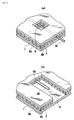
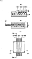
- Figure 1 is a schematic view illustrating the microfluid-system supporting unit in the first embodiment of the present invention.
- Figure 1(a) is a crosssectional view of the microfluid-system supporting unit; and
- Figure 1(b) is a top view of the unit of Figure 1(a), of which the sectional view as seen in the arrowed Ia-Ia line direction corresponds to Figure 1(a).
- the microfluid-system supporting unit in the first embodiment of the present invention has a first supporting plate 1; a first filament bundle of multiple hollow filaments in any shape 501 to 508 placed on the first supporting plate 1; and a second filament bundle of multiple hollow filaments 511 to 518, placed in the direction crosswise to a first filament bundle of thatabove.
- the supporting unit has a second supporting plate 2 on the side of the hollow filaments opposite to the first supporting plate 1. The first and second filament bundles are held between the first supportingplate 1 and the second supporting plate 2 respectively with adhesive layers 8a and 8b.
- Each of these hollow filaments has a functional particular region 301 to 308 or 311 to 318 internally.
- These multiple hollow filaments make a channel for delivery of drug solutions in the microfluid-system supporting unit in the first embodiment.
- the first and second filament bundles are placed crosswise. Although it is difficult or impossible, for example of chemical chip, to place a channel crosswise on the same plane, the first and second filament bundles according to the invention can be formed crosswise easily.
- the inner and outer diameters of the hollow filament may vary according to applications, but the inner diameter is preferably, approximately ⁇ 0.01 to 1.0 mm, because the flow rate per unit time is often in the order of milliliter (mL) to microliter ( ⁇ L).
- a resin material such as polyimide (PI), polyether ether ketone (PEEK), polyether imide (PEI), polyphenylene sulfide (PPS), or tetrafluoroethylene-perfluoroalkoxyethylene copolymer (PFA) is particularly favorably used in preparation of the hollow filament having such diameters.
- An inner diameter of less than ⁇ 0.01 mm may lead to troubles such as clogging, because the influence of the interfacial resistance between the internal wall of hollow filament and the fluid becomes considerably higher.
- an inner diameter of more than ⁇ 1.0 mm may possibly demand high pressure to feed fluid continuously, leading for example to increase of the load on other parts and contamination of the liquid by air bubbles.
- the hollow filament is preferably chemically resistant, if the fluid flowing in the hollow filament is chemically reactive.
- any one of such tubes may be used, as selected properly according to applications.
- examples thereof include organic materials such as polyvinyl chloride resin (PVC), polyvinylidene chloride resin, polyvinyl acetate resin, polyvinylalcohol resin (PVA), polystyrene resin (PS), acrylonitrile-butadiene-styrene copolymer resin (ABS), polyethylene resin (PE), ethylene-vinyl acetate copolymer resin (EVA), polypropylene resin (PP), poly-4-methylpentene resin (TPX), polymethylmethacrylate resin (PMMA), polyether ether ketone resin (PEEK), polyimide resin (PI), polyether imide resin (PEI), polyphenylene sulfide resin (PPS), cellulose acetate, polytetrafluoroethylene resin (PTFE), tetrafluoroethylene-propylene hexafluoride
- PVC polyvinyl chloride resin
- PVA poly
- Examples of the functions of the internal particular region in hollow filament 301 to 308, or 311 to 318 include adsorption-desorption, ion exchange, separation, removal, partition, oxidation-reduction, and the like.
- the particular region preferablyhas at least one of the functions described above.
- the filler may be selected from inorganic fillers and resin fillers according to applications.
- the inorganic fillers include, for example, materials based on silica gel, activated carbon, alumina, zirconia, titania, or the like.
- Silica gel filler is preferably used at a pH of 8 or less, because it is soluble in basic aqueous solutions.
- the resin fillers include synthetic polymer gels such as of styrene-divinylbenzene copolymer and polymethacrylate, natural polymer gels, and the like.
- the hardness and micropore size of the resin fillers are easier to adjust according to applications, and the resin fillers can be used in a wide pH range (approximately pH 2 to 13).
- a particular DNA probe, antibody, or ion exchange, or alternatively, for example, a catalytic metal, maybe introduced onto the surface of the filler according to applications.
- Examples of the functions provided to the hollow filament by filler packing include adsorption-desorption, ion exchange, separation, removal, partition, oxidation-reduction, and the like.
- graft-polymerization side chains are formed, for example, by a glycidyl methacrylate (GMA) monomer coming in contact with a generating radicals by irradiating a particular region of the tube for hollow filament with an energy-rich radiation ray such as electron beam or gamma ray.
- GMA glycidyl methacrylate
- a desirable functional group is introduced on the side chains.
- Processing by graft polymerization is preferably, because it is possible to introduce a functional group in a particular region of a tube in any shape and give the tube various functions. Examples of the functions endowed to the hollow filament by graft polymerization include adsorption-desorption, ion exchange, separation, partition, and the like.
- the function is endowed by forming a porous material in the particular internal region of at least one hollow filament, for example, use of a porous silica material is preferable. It is possible to prepare the porous structure of the porous silica material having a small diameter of ⁇ 0.01 to 0.1 mm in a hollow filament easily, because it is formed by supplying and polymerizing a monomer in the hollow filament. It is also possible to give a function according to applications, because the specification of the porous material structure (raw material, skeletal size, pore size, surface modification, and the like) is freely adjustable. Examples of the functions endowed by forming a porous material in the hollow filament include adsorption-desorption, ion exchange, separation, partition, and the like.
- the particular region of at least one hollow filament for the photochemical reaction or spectrometric analysis is preferably transparent to light.
- the light transparency may vary according to applications, but is preferably 80% or more, more preferably 90% or more, at the desirable wavelength.
- the first supporting plate 1 and/or the second supporting plate 2 in the regions close to the particular region of hollow filament preferably satisfy the requirement in light transparency described above. If present, the adhesive layers in the regions close to the particular region of hollow filament are also preferably light transparent.
- Figure 2 is a perspective view illustrating the structure of a hollow filament in the microfluid-system supporting unit in the second embodiment of the present invention
- Figure 2(a) is a perspective view of a hollow filament 58 in the area where it is exposed in the face of the unit in the both directions
- Figure 2(b) is a perspective view of the hollow filament in the area where it is exposed outside the face of the unit.
- an exposure window 9 maybe favorably formed through the first supporting plate 1 and the adhesive layer 8a and/or the second supporting plate 2 and the adhesion 8b, exposing the hollow filament 58.
- part of at least one hollow filament is preferably exposed through the first supporting plate, or alternatively, through the first supporting plate and/or the second supporting plate, if the second supporting plate is present.
- the adhesive layer is light low-transparent or opaque, the hollow filament is preferably placed in such a way that it is exposed through the adhesive layer.
- a metal layer may be formed on a particular region of at least one hollow filament.
- a terminal for example for applying voltage, by forming a metal layer 59 on part of the exposed hollow filament 58.
- a single layer or multiple layers of Cu, Al, nickel (Ni), chromium (Cr), gold (Au), or the like are formed by plating or vapor deposition favorably.
- At least one hollow filament in any shape having no function in the particular internal region may be placed on the first supporting plate.
- some samples are collected without pretreatment for reference.
- At least one hollow filament may be placed crosswise with at least another hollow filament.
- the channels are to be placed in the number according to the desirable analysis samples and reaction steps.
- the channel should also have a certain length needed for temperature adjustment, securement of reaction time, and others. In such cases, it is possible to wire the channels (hollow filaments) without need for considering the wiring-prohibited area during pattern design, because the hollow filaments may be placed crosswise freely.
- At least one hollow filament may be placed crosswise to the hollow filament itself.
- An example thereof is a reactor unit of causing a reaction by delivering raw materials to the region of the filament having a certain function by feeding them into the hollow filament continuous or intermittently.
- the raw materials flowing in the region of a hollow filament present are heated or cooled, by bringing a temperature control device such as heater or Peltier element into contact with a particular region of the reactor unit.
- a temperature control device such as heater or Peltier element
- Layers of an adhesive agent may be formed on the hollow filament-sided surface of the first supporting plate and/or the second supporting plate, to make fixation of the hollow filament easier.
- adhesive layers 8a and 8b in Figure 1(a) may be formed on the hollow filament-sided surface of the first supporting plate and/or the second supporting plate, to make fixation of the hollow filament easier.
- the first adhesive layer 8a formed on the surface of the first supporting plate 1 is preferably made of a pressure-sensitive or photosensitive adhesive agent.
- these materials are sensitive to pressure, light, and heat.
- Application of such a stimulus which increases the tackiness, adhesiveness, and tenacity by embedding, is favorable when the hollow filament (hollow capillary) pattern is placed mechanically.
- the pressure-sensitive adhesive is favorably an adhesive agent of a high-molecular weight synthetic rubber or silicone resin.
- the high-molecular weight synthetic rubber adhesive agents include isobutylene polymers such as Vistanex MML-120 (trade name, manufactured by Tonex Co. Ltd.), acrylonitrile-butadiene rubbers such as Nipol N1432 (trade name, manufactured by Zeon Corporation), chlorosulfonated polyethylenes such as Hyperlon® 20 manufactured by E.I. du Pont de Nemours and Company, and the like.
- the first adhesive layer 8a may be formed by dissolving these materials in a solvent and coating directly and drying the solution on the first supporting plate 1.
- a crosslinking agent may be added to these materials as needed additionally.
- Acrylic resin-based two-sided adhesive tapes such as Product No. 500 manufactured by Nitto Denko Corporation and VHB A-10, A-20, A-30, and others (trade name, manufactured by 3M) may also be used.
- silicone resin-based adhesive agents include silicone adhesive agents containing a silicon rubber of a high-molecular weight polydimethylsiloxane or polymethylphenylsiloxane having a silanol group at the terminal and a silicon resin such as methylsilicone resin or methylphenylsilicone as the principal components.
- the resin may be crosslinked in various ways, for adjustment of its aggregation potential.
- the crosslinking may be performed, for example, by addition reaction of silane, alkoxy condensation reaction, acetoxy condensation reaction, or radical reaction for example with a peroxide.
- YR3286 (trade name, manufactured by GE Toshiba Silicones Co., Ltd.), TSR1521 (trade name, manufactured by GE Toshiba Silicones Co., Ltd.), DKQ9-9009 (trade name, manufactured by Dow Corning), and the like.
- the photosensitive adhesive agent examples include dry-film resists and solder-resist inks used as the etching resist for printed circuit boards, photosensitive build-up materials for printed circuit boards, and the like. Specific examples thereof include H-K440 (trade name, manufactured by Hitachi Chemical Co., Ltd.), Probimer manufactured by Ciba-Geigy Corp., and the like.
- the photobia materials used in the build-up wiring board application withstand the conditions in the production process of printed wiring boards and the component-mounting step with a solder.
- any one of these materials may be used, if it is a composition containing a copolymer or monomer having a photocrosslinkable functional group and/or a composition containing a photocrosslinkable and thermal crosslinkable functional group and a thermal polymerization initiator.
- the photosensitive adhesive agents include epoxy resin, brominated epoxy resin, alicyclic epoxy resins such as rubber-modified epoxy resin, and rubber-dispersed epoxy resin, bisphenol A-based epoxy resins, and acid-modified derivatives of these epoxy resins, and the like.
- unsaturated acid-modified derivatives of these epoxy resins are used favorably, when the resin is hardened by photoirradiation.
- unsaturated acids include maleic anhydride, tetrahydrophthalic anhydride, itaconic anhydride, acrylic acid, methacrylic acid, and the like.
- the modified product is prepared by allowing an unsaturated carboxylic acid to react with the epoxy groups of an epoxy resin at a blending ratio equivalent to 1 or less.
- thermosetting materials such as melamine resin and cyanate ester resin, combinations thereof with a phenol resin, and the like. It is possible to harden the adhesive even in the region behind crossing channels where no light is irradiated, by adding such a thermosetting material.
- a natural rubber or the high-molecular weight synthetic rubber described above such as acrylonitrile-butadiene rubber, acrylic rubber, SBR, carboxylic acid-modified acrylonitrile butadiene rubber, carboxylic acid-modified acrylic rubber, crosslinked NBR particles, or carboxylic acid-modified crosslinked NBR particles may be added, to give flexibility.
- a filler may also be blended.
- the fillers include inorganic fine particles such as of silica, fused silica, talc, alumina, hydrated alumina, barium sulfate, calcium hydroxide, Aerojil, and calcium carbonate; organic fine particles such as of powdery epoxy resin and powdery polyimide particle; powdery polytetrafluoroethylene particles, and the like.
- the filler may be processed previously by coupling treatment. These materials are dispersed, for example, by a knownblendingmethod, for example, in a kneader, ball mill, bead mill, or three-roll mill.
- the photosensitive resin may be formed by a method of coating a liquid resin for example by a method of roll coating, curtain coating, or dip coating, or laminating an insulative resin film on a carrier film.
- a method of coating a liquid resin for example by a method of roll coating, curtain coating, or dip coating, or laminating an insulative resin film on a carrier film.
- Specific examples thereof include photobia film product BF-8000, manufactured by Hitachi Chemical Co., Ltd. and the like.
- first adhesive layer 8a may also be used for the second adhesive layer 8b.
- the method of placing, or preferably fixing, hollow filaments on the first supporting plate is advantageous in that it is possible to control various environmental factors such as surrounding temperature, electric field, and magnetic field more easily than when the hollow filaments are used alone.
- the method is particularly advantageous when a chemical reaction or analysis is carried out especially in a microreaction and microanalysis system. It is also advantageous in that it is possible to place multiple hollow filaments densely, it is easy to be aligned with other components and to be connected with.
- the multiple hollow filaments are preferably the same in length as each other, frombalancing the conditions such as reaction time, electrophoretic distance, and the amount of energy applied. That is, it is preferable to make an energy applied to the sample during its flow from the inlet to the outlet of channel identical and to make the energy transmitted from a hollow filament to other hollow filaments almost the same. From the viewpoint above, it is preferable to make the hollow filaments held between two or more supportingplates, so that the distribution of the heat between the hollow filaments is uniformized.
- the microfluid-system supporting unit according to the present invention preferably has a structure having an additional second supporting plate, so that at least one hollow filament is held between the first and second supporting plates.
- the multiple hollow filaments are placed, as they are separated from each other at the same distance. Further, the thickness of between inner and outer of the multiple hollow filament is preferably the same.
- the material, shape and size of the first and second supporting plates may be selected properly according to applications, and the favorable ranges of the plate thickness, film thickness, and others often vary according to the purpose and the desirable function.
- favorable are epoxy and polyimide resin plates used in printed wiring boards and others; and polyimide films such as Kapton® film manufactured by E.I. du Pont de Nemours and Company, PET films such as Lumirror® film manufactured by Toray Industries, Inc., and PPS films such as Torelina® film manufactured by Toray Co., Ltd that are used for flexible printed wiring boards; and the like.
- the plate thickness (film thickness) of the first supporting plate is preferably thicker, more preferably 0.05 mm or more, for improvement in electric resistance.
- the thickness of the first supporting plate is preferably further thicker, more preferably 0.5 mm or more.
- the plate thickness (film thickness) of the first supporting plate is preferably thinner, more preferably 0.5 mm or less.
- a so-called flexible circuit board or printed circuit board having a metal pattern for example of copper formed on the surface by etching, plating, or the like may be used as the supporting plate. It is thus possible to form a terminal or a circuit having various mounted parts and elements including micromachine, heating element, piezoelectric element, various sensors of temperature, pressure, deformation, vibration, voltage, magnetic field, and others; electronic parts such as resistance, capacitor, coil, transistor, and IC; optical parts such as semiconductor laser (LD), light-emitting diode (LED), and photodiode (PD), and thus to simplify the system easily.
- LD semiconductor laser
- LED light-emitting diode
- PD photodiode
- the various materials used for the first supporting plate 1 described above may also be used for the second supporting plate 2.
- Presence of a second adhesive layer 8b between the second supporting plate 2 and the second filament bundle of multiple hollow filaments 511 to 518 is preferable, because it is more effective in improving protection of the a first filament bundle of multiple hollow filament 501 to 508 and the second filament bundle.
- Use a mesh or porous film or fabric as the second supporting plate 2 prevents troubles such as enclosure of air bubbles during lamination.
- the mesh films or fabrics include polyestermeshTB-70 (type) manufactured by Tokyo screen Co. , Ltd. , and the like.
- Examples of the porous films include Duraguard (trade name, manufactured by Celanese Chemicals), Celgard 2400 (trade name, manufactured by Daicel Chemical Industries), Ltd., and the like.
- At least one hollow filament preferably has an inlet port for receiving a fluid from outside and/or an outlet port for discharging the fluid to outside.
- the structure, shape, and position of the ports are arbitrary.
- Figure 3 (a) is a perspective view of the microfluid-system supporting unit having a port (opening) in the third embodiment of the present invention
- Figure 3(b) is a perspective view of the microfluid-system supporting unit having a port (needle) in the third embodiment of the present invention.
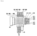
- Figure 4 is a perspective view of the microfluid-system supporting unit having a joint in the fourth embodiment of the present invention.
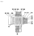
- Figure 5 is a perspective view of the microfluid-system supporting unit having a joint in the fifth embodiment of the present invention.
- It is formed, for example, by a method shown in Figure 3(a) of forming a hole 41 having a diameter almost the same as or smaller than the inner or outer diameter of the hollow filament 58, for example by laser-beam machining or cutting, and sealing the hole with a silicone rubber (not shown in the Figure), or a method shown in Figure 3(b) of thrusting a needle 42 having a diameter almost the same into the hollow filament 58 and fixing the needle 42.
- it may be formed by a method of forming a joint 43 for fluid at the terminal of the hollow filament, as shown in Figures 4 and 5.
- the port such as the joint 43 is preferably fixed to the first supporting plate or to the first supporting plate and/or the second supporting plate if the second supporting plate is present.
- the size of the hole 41, needle 42, joint 43, and others is arbitrary, care should be given to the size, because an excessively large diameter, for example of twice or more, may lead to decrease in the advantage of miniaturization by increase in unneeded capacity and possibly cause contamination of air bubbles.
- the hollow filament 58 is preferably elastic, when a microfluid-system supporting unit having a through hole in part thereof is used as a micorpump or a microvalve, while the fluid therein is fed in pulsed flow by a cam motor, by applying a sequential force to part of the hollow filament 58 and thus deforming the region of the hollow filament for example.
- the hollow filament 58 preferably has a Young's modulus of 10 3 MPa or less.
- Figure 6(a) is a perspective view of the microfluid-system supporting unit having a relay unit in the sixth embodiment of the present invention
- Figure 6(b) is a sectional view of the supporting unit of Figure 6(a) as seen in the arrowed VIa-VIa direction.
- the microfluid-system supporting unit according to the present invention preferably has an opening of relay unit 6, as shown in Figures 6(a) and Figure 6(b).
- the relay unit 6 connects the channels of hollow filament, and has a structure in which a hollow filament 58 is exposed between the first adhesive layer 8a and the second adhesive layer 8b.
- the exposed hollow filament 58 feeds a fluid.
- the relay unit 6 mixes or distributes the fed fluid.
- the shape and size of the relay unit 6 are decided properly according to the flow rate of the fluid.
- the relay unit 6 may be in a circular rod shape having a diameter of approximately ⁇ 2 to 7 mm. It is possible to mix the fluid flowing in the hollow filaments 58 and distribute it from the relay unit 6. It is also possible to inject a new fluid into the relay unit inward and withdraw the fluid in the relay unit 6 outward, by making the relay unit 6 have an open structure by integrating the second supporting plate 2 with the relay unit 6. If the relay unit 6 is only for mixing or distribution, the relay unit maybe in a closed structure in which the second supporting plate 2 does not have an opening.
- the hollow filaments should not be always crossed at an angle of 90 degrees, but may be crossed at any angle.
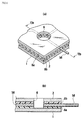
- Figure 7(a) is a sectional view of the top view of the microfluid-system supporting unit in the seventh embodiment of the present invention shown in Figure 7(c), as seen in the arrowed VIIa-VIIa line direction
- Figure 7(b) is a sectional view of the top view shown in Figure 7(c) as seen in the arrowed VIIb-VIIb line direction.
- the particular region having a function is not shown in Figures 7 to 9.
- Figure 8 is a perspective view of the microfluid-system supporting unit in the eighth embodiment of the present invention.
- the hollow filaments may contain only multiple hollow filaments 501 to 508 extending in one direction.
- Figure 9 is a perspective view of the microfluid-system supporting unit in the ninth embodiment of the present invention. As shown in Figure 9, multiple curved hollow filaments 511 to 518 may be placed.
- the hollow filaments may not be placed in multiples, and thus, a single hollow filament may be placed.
- Hollow filaments 501 to 508 and 511 to 518 of a high-performance engineering plastic tube (material: PEEK, inner diameter: 0.2 mm, outer diameter: 0.4 mm) manufactured by Nirei Industry Co., Ltd. were placed at desirable positions on the first supporting plate 1, by using an NC wiring apparatus allowing ultrasonic vibration as well as load-output and NC control and having a movable X-Y table.
- a load of 80 g and ultrasonic vibration at a frequency of 30 kHz were applied to the hollow filaments 501 to 508 and 511 to 518 in the shape of circular arc of 5 mm in radius, and crosswise oriented regions were also formed.
- a polyimide film 300H registered trade name: Kapton
- Kapton manufactured by E.I. du Pont de Nemours and Company was used as the second supporting plate 2
- a second hollow filament bundle of multiple hollow filaments 511 to 518 are placed.
- the laminate was then cut into a wide cruciform shape along the desired cutting lines shown in Figure 1(b), while forming holes having a diameter of ⁇ 0.2 mm at an interval of 0.1 mm at a pulse width of 5 ms and a shot number of 4 by using a laser-drilling machine for forming fine diameter holes in printed circuit board.
- a certain area of the first supporting plate 1 close to the terminal of the hollow filaments 501 to 508 and 511 to 518 was then removed, exposing the terminals of 10 mm in length respectively of the first hollow filament bundle of eight hollow filaments 501 to 508 having a total length of 20 cm and the second hollow filament bundle of 8 hollow filaments 511 to 518 having a total length of 20 cm, to give a microfluid-system supporting unit.
- the deviation of the position of the channels of the first hollow filament bundle of multiple hollow filaments 501 to 508, and the second hollow filament bundle of multiple hollow filaments 511 to 518 was in the range of ⁇ 10 ⁇ m with respect to the value designed in the engineering drawing.
- the microfluid-system supporting unit was placed in a constant-temperature oven at 80°C; a color liquid ink is supplied from one end and the period until the ink flows out of the other end was determined with a measurement device such as stopwatch; the eight hollow filaments ejected the ink almost at the same timing ( ⁇ 1 second or less) from the other end.
- An aluminum plate having a thickness of 0.5 mm carrying a non-adhesive layer of a pressure-sensitive adhesive S9009 (trade name, manufactured by Dow Corning Asia Co., Ltd.) having a thickness of 100 ⁇ m was used as the first supporting plate.
- Glass tubes ESG-2 manufactured by Hagitec Co., Ltd. (inner diameter 0.8 mm, outer diameter: 1 mm) were placed thereon by using a NC wiring apparatus allowing ultrasonic vibration as well as load-output and NC control and having a movable X-Y table.
- a load of 100 g and ultrasonic vibration at a frequency of 20 kHz were applied to the hollow filaments placed.
- the hollow filaments were placed in a circular arc shape having a radius of 10 mm, and areas of intersection were also formed. Application of the load and ultrasonic vibration was eliminated in the area close to the intersection.
- a polyimide film 200H (registered trade name: Kapton) manufactured by E.I. du Pont de Nemours and Company was used as the second supporting plate and laminated on the hollow filament-carrying supporting unit by vacuum lamination. Thermocouples for temperature measurement were embedded then in the areas close to the inlet, outlet, and intersection of respective hollow filaments.
- the composite was cut into a piece in a desirable shape by using an outside shape-processing machine for printed circuit boards. Removal of a predetermined area of the supporting plate gave a microfluid-system supporting unit containing 12 hollow filaments having a total length of 40 cm in the shape in which a region thereof of 50 mm in length is exposed. The deviation of the position of the hollow filaments placed was in the range of less than ⁇ 20 ⁇ m with respect the value designed in the engineering drawing. The hollow filaments in the entire area of placement, in particular in the area at intersection, were not damaged.
- the entire rear face of the aluminum plate was brought into contact with a heater Film Heat FTH-40 manufactured by Kyohritsu Electronic Industry Co., Ltd. which was set to 90°C. Water at approximately 20°C was fed from one end, and the temperature of the water discharged from the other end was determined to be 88 ⁇ 1°C. The temperature of each of the inlet, outlet, and intersection was 89 ⁇ 0.5°C, indicating that the temperature was accurately controlled.
- a copper foil having a thickness of 35 ⁇ m carrying an adhesive agent, which is non-adhesive at room temperature, S9009 (trade name, manufactured by Dow Corning Asia Co., Ltd., thickness: 200 ⁇ m) was used as the first supporting plate 1.
- High-performance engineering plastic tubes material: PEEK, inner diameter: 0.2 mm, outer diameter: 0.4 mm
- Nirei Industry Co., Ltd. were placed thereon, by using a multiwire-wiring machine allowing ultrasonic vibration as well as load-output and NC control and having a movable X-Y table.
- a load of 80 g and ultrasonic vibration at a frequency of 30 kHz were applied to the hollow filaments58 placed.
- the hollow filaments 58 were placed in the shape of circular arc of 5 mm in radius, and crossing regions were also formed. Application of the load and ultrasonic vibration was eliminated in the area close to the intersection.
- a polyimide film 200H (registered trade name: Kapton) manufactured by E.I. du Pont de Nemours and Company as the second supporting plate 2, carrying the adhesive agent described above S9009 (trade name, manufactured by Dow Corning Asia Co., Ltd., thickness 200 ⁇ m), was laminated on the hollow filament 58-placed surface by vacuum lamination.
- Holes having a diameter of ⁇ 0.2 mm were formed then in the second supporting plate 2 and the hollow filaments 58 at the position of the relay unit 6, by using a laser-drilling machine for forming fine diameter holes in printed circuit board at a pulse width of 5 ms and a shot number of 4.
- the outside shape was the processed with a rooter, to give a microfluid-system supporting unit having a relay unit 6 to which multiple channels are connected.
- microfluid-system supporting units prepared in Preparative Examples 1 to 3 have a structure that will have an additional function, for example, by packing of a filler, graft polymerization, formation of a porous material, or the like.
- Fluoroplastic EXLON PFA tubes (trade name, inner diameter: 0.5 mm, outer diameter: 1.5 mm) manufactured by Iwase Co. , Ltd. , were placed as the hollow filaments, by using an NC wiring apparatus allowing ultrasonic vibration as well as load-output and NC control and having a movable X-Y table.
- a load of 120 g and ultrasonic vibration at a frequency of 20 kHz were applied to the hollow filaments placed, which were placed closely in the straight-line shape of 40 cm in length. No load or ultrasonic vibration was applied in the area close to the intersection.
- a polyimide film 200H (registered trade name: Kapton) manufactured by E.I. du Pont de Nemours and Company as the second supporting plate was laminated over the hollow filaments by vacuum lamination.
- the composite was cut into a piece in a desirable shape by using an outside shape-processing machine for printed circuit boards. Removal of a predetermined area of the supporting plate gave a microfluid-system supporting unit containing 12 hollow filaments having a total length of 40 cm in the shape in which the region thereof of 50 mm in length is exposed. The deviation of the position of the hollow filaments formed was in the range of less than ⁇ 20 ⁇ m with respect the value designed in the engineering drawing, and the hollow filaments in the entire area of placement, in particular in the area at intersection, were not damaged.
- a metal ion-exchanging function was given thereto by irradiating the particular region of the hollow filaments with electron beam, thus graft-polymerizing glycidyl methacrylate (GMA) thereon, and converting the epoxy groups in the graft polymer chains into the iminodiacetic acid group while supplying an aqueous solution of disodium iminodiacetate/dimethylsulfoxide at a constant temperature and at a constant flow rate into the tube.
- GMA glycidyl methacrylate
- Fluoroplastic tubes (trade name: EXLON PFA tube, inner diameter: 0.5 mm, outer diameter: 1.5 mm) manufactured by Iwase Co., Ltd. were used. The tubes were cut into pieces of approximately 4 0 cm in length, and were fixed on particular regions 301 to 308, while a polyethylene filter was plugged into each of them from one end. 0.01 cc of a gel pack filler (trade name: TM70, manufactured by Hitachi Chemical Co., Ltd.) was packed in the tubes, to give hollow filaments 501 to 508.
- a gel pack filler (trade name: TM70, manufactured by Hitachi Chemical Co., Ltd.) was packed in the tubes, to give hollow filaments 501 to 508.
- An aluminum plate having a thickness of 0.5 mm carrying a non-adhesive pressure-sensitive adhesive (trade name: S9009, manufactured by Dow Corning Asia Co., Ltd., thickness: 100 ⁇ m) was used as the first supporting plate 1.
- the hollow filaments are placed thereon by using an NC wiring apparatus allowing ultrasonic vibration as well as load-output and NC control and having a movable X-Y table.
- the hollow filaments 501 to 508 were placed closely in a straight line shape of 40 cm in length, while a load of 150 g and ultrasonic vibration at a frequency of 20 kHz were applied.
- a polyimide film 200H (registered trade name: Kapton) manufactured by E. I. du Pont de Nemours and Company , as the second supporting plate 2 was laminated over the hollow filaments 501 to 508 by vacuum lamination.
- the composite was then cut into a piece in a desirable shape by using an outside shape-processing machine for printed circuit boards. Removal of a predetermined area of the supporting plate gave a microfluid-system supporting unit containing 8 hollow filaments 501 to 508 having a total length of 40 cm in the shape in which the region thereof of 50 mm in length is exposed.
- the deviation of the position of the channels formed with the hollow filaments 501 to 508 was in the range of less than ⁇ 20 ⁇ m with respect the value designed in the engineering drawing, and the hollow filaments of hollow filaments 501 to 508 in the entire area of placement, in particular in the area at intersection, were not damaged.
- microfluid-system supporting unit according to the present invention can be produced easily. There is no restriction on the number of the steps and capacity of the reaction and analysis. It is also possible to obtain a long channel length in the order of cm.
- themicrofluid-system supporting unit provides a fluid circuit (microfluid system) higher in precision and lower deviation during production. It also provides a miniature microfluid system having a complicated fluid circuit, because at least one hollow filament may be placed crosswise three-dimensionally.
Landscapes
- Chemical & Material Sciences (AREA)
- Health & Medical Sciences (AREA)
- Analytical Chemistry (AREA)
- General Health & Medical Sciences (AREA)
- Chemical Kinetics & Catalysis (AREA)
- Life Sciences & Earth Sciences (AREA)
- Dispersion Chemistry (AREA)
- Hematology (AREA)
- Clinical Laboratory Science (AREA)
- Pathology (AREA)
- Physics & Mathematics (AREA)
- Biochemistry (AREA)
- General Physics & Mathematics (AREA)
- Immunology (AREA)
- Organic Chemistry (AREA)
- Hydrology & Water Resources (AREA)
- Physical Or Chemical Processes And Apparatus (AREA)
- Micromachines (AREA)
- Automatic Analysis And Handling Materials Therefor (AREA)
- Investigating Or Analysing Materials By The Use Of Chemical Reactions (AREA)
- Apparatus Associated With Microorganisms And Enzymes (AREA)
- Inorganic Fibers (AREA)
- Artificial Filaments (AREA)
Applications Claiming Priority (4)
| Application Number | Priority Date | Filing Date | Title |
|---|---|---|---|
| JP2004041379 | 2004-02-18 | ||
| JP2004133265 | 2004-04-28 | ||
| JP2004343821 | 2004-11-29 | ||
| PCT/JP2005/002433 WO2005084792A1 (ja) | 2004-02-18 | 2005-02-17 | マイクロ流体システム用支持ユニット |
Publications (3)
| Publication Number | Publication Date |
|---|---|
| EP1738820A1 true EP1738820A1 (de) | 2007-01-03 |
| EP1738820A4 EP1738820A4 (de) | 2007-04-04 |
| EP1738820B1 EP1738820B1 (de) | 2009-11-11 |
Family
ID=34923009
Family Applications (1)
| Application Number | Title | Priority Date | Filing Date |
|---|---|---|---|
| EP05719235A Not-in-force EP1738820B1 (de) | 2004-02-18 | 2005-02-17 | Mikrofluidische Einheit mit Hohlfaser-Kanal |
Country Status (9)
| Country | Link |
|---|---|
| US (2) | US20070183933A1 (de) |
| EP (1) | EP1738820B1 (de) |
| JP (5) | JPWO2005084792A1 (de) |
| KR (1) | KR100927288B1 (de) |
| CN (2) | CN101722065A (de) |
| AT (1) | ATE448018T1 (de) |
| DE (1) | DE602005017602D1 (de) |
| TW (1) | TWI299402B (de) |
| WO (1) | WO2005084792A1 (de) |
Cited By (3)
| Publication number | Priority date | Publication date | Assignee | Title |
|---|---|---|---|---|
| EP2184103A1 (de) * | 2008-11-11 | 2010-05-12 | Onea Engineering Austria GmbH | Modularer Reaktor |
| WO2012143693A1 (en) * | 2011-04-18 | 2012-10-26 | Martin John Hofmann | Apparatus and methods for fluid processing and flow control |
| US11076480B2 (en) | 2019-01-29 | 2021-07-27 | At&S Austria Technologie & Systemtechnik Aktiengesellschaft | Component carrier with embedded filament |
Families Citing this family (22)
| Publication number | Priority date | Publication date | Assignee | Title |
|---|---|---|---|---|
| JP3933058B2 (ja) * | 2002-02-25 | 2007-06-20 | 日立化成工業株式会社 | マイクロ流体システム用支持ユニット及びその製造方法 |
| JPWO2005084792A1 (ja) * | 2004-02-18 | 2007-08-02 | 日立化成工業株式会社 | マイクロ流体システム用支持ユニット |
| JP4687653B2 (ja) * | 2004-11-30 | 2011-05-25 | 日立化成工業株式会社 | 分析前処理用部品 |
| EP1832339A1 (de) * | 2004-12-09 | 2007-09-12 | Hitachi Chemical Co., Ltd. | Trageinheit für mikrofluidsystem und herstellungsverfahren dafür |
| JP4899681B2 (ja) * | 2006-07-18 | 2012-03-21 | 富士ゼロックス株式会社 | マイクロ流路デバイス |
| JP5151204B2 (ja) * | 2007-03-27 | 2013-02-27 | 富士ゼロックス株式会社 | マイクロ流路デバイス及びマイクロ流路デバイスの製造方法 |
| JP2008281366A (ja) * | 2007-05-08 | 2008-11-20 | Hitachi Chem Co Ltd | マイクロ流体システム用支持ユニット |
| JP5012186B2 (ja) * | 2007-05-08 | 2012-08-29 | 日立化成工業株式会社 | マイクロ流体システム用支持ユニットの製造方法 |
| JP5119848B2 (ja) * | 2007-10-12 | 2013-01-16 | 富士ゼロックス株式会社 | マイクロリアクタ装置 |
| JP2010115624A (ja) | 2008-11-14 | 2010-05-27 | Fuji Xerox Co Ltd | マイクロ流路デバイス、分離装置、並びに、分離方法 |
| JP5003702B2 (ja) | 2009-03-16 | 2012-08-15 | 富士ゼロックス株式会社 | マイクロ流体素子及びマイクロ流体制御方法 |
| WO2011019516A2 (en) * | 2009-08-11 | 2011-02-17 | Baril Corporation | Microfluidic diagnostic device |
| WO2012017515A1 (ja) * | 2010-08-03 | 2012-02-09 | ミライアル株式会社 | マイクロ流路デバイス |
| HUE045497T2 (hu) | 2011-12-21 | 2019-12-30 | Huawei Tech Co Ltd | Nagyon rövid hangmagasság detektálás és kódolás |
| JP2012145581A (ja) * | 2012-01-16 | 2012-08-02 | Hitachi Chem Co Ltd | マイクロ流体システム用支持ユニットの製造方法 |
| EP3120928A1 (de) * | 2015-07-24 | 2017-01-25 | Centre National De La Recherche Scientifique | Fluidvorrichtungen mit mindestens einer betätigbaren faser |
| EP3120927A1 (de) * | 2015-07-24 | 2017-01-25 | Centre National De La Recherche Scientifique | Verwickelte fluidische vorrichtung |
| TWI579564B (zh) * | 2015-09-15 | 2017-04-21 | Zhi-Xi Hu | Microfluidic transmission and detection of the wafer structure of biological samples |
| GB2559520B (en) * | 2015-11-18 | 2021-07-28 | Hamamatsu Photonics Kk | Concentration measurement method |
| CN107344125A (zh) * | 2016-05-05 | 2017-11-14 | 李榕生 | 流体驱动方式特异的廉价的艾滋病诊断用微流控装置 |
| CN109758995B (zh) * | 2019-03-05 | 2020-12-11 | 大连理工大学 | 一种通用型荧光流体光化学微反应器件及其3d打印制造方法 |
| GB201913529D0 (en) * | 2019-09-19 | 2019-11-06 | Tanriverdi Ugur | Method And Apparatus |
Citations (5)
| Publication number | Priority date | Publication date | Assignee | Title |
|---|---|---|---|---|
| US4959152A (en) * | 1989-03-24 | 1990-09-25 | The Standard Oil Company | Hollow fiber separation module and method for the use thereof |
| US5070606A (en) * | 1988-07-25 | 1991-12-10 | Minnesota Mining And Manufacturing Company | Method for producing a sheet member containing at least one enclosed channel |
| DE4308697A1 (de) * | 1993-03-18 | 1994-09-22 | Durst Franz Prof Dr Dr H C | Verfahren zur Anreicherung eines ersten gasförmigen oder flüssigen Mediums mit einem zweiten Gas oder einer zweiten Flüssigkeit sowie ein Reaktor zur Durchführung des Verfahrens |
| FR2813073A1 (fr) * | 2000-12-19 | 2002-02-22 | Commissariat Energie Atomique | Dispositif de positionnement et de guidage pour la connexion etanche de capillaires a un micro-composant |
| EP1486455A1 (de) * | 2002-02-25 | 2004-12-15 | Hitachi Chemical Company, Ltd. | Mikrofluidsystemstützeinheit und herstellungsverfahren dafür |
Family Cites Families (56)
| Publication number | Priority date | Publication date | Assignee | Title |
|---|---|---|---|---|
| US3674602A (en) * | 1969-10-09 | 1972-07-04 | Photocircuits Corp | Apparatus for making wire scribed circuit boards |
| US3702658A (en) * | 1971-02-24 | 1972-11-14 | Du Pont | Permeation separation apparatus |
| US3915652A (en) * | 1973-08-16 | 1975-10-28 | Samuel Natelson | Means for transferring a liquid in a capillary open at both ends to an analyzing system |
| US4693778A (en) * | 1985-07-19 | 1987-09-15 | Kollmorgen Technologies Corporation | Apparatus for making scribed circuit boards and circuit board modifications |
| US4970034A (en) * | 1988-09-23 | 1990-11-13 | W. R. Grace & Co.-Conn. | Process for preparing isotropic microporous polysulfone membranes |
| US5236665A (en) * | 1988-10-20 | 1993-08-17 | Baxter International Inc. | Hollow fiber treatment apparatus and membrane oxygenator |
| US5174900A (en) * | 1989-03-24 | 1992-12-29 | The Standard Oil Company | Apparatus for separation and for treatment of fluid feedstreams, wafers for use therein and related methods |
| US5264171A (en) * | 1991-12-31 | 1993-11-23 | Hoechst Celanese Corporation | Method of making spiral-wound hollow fiber membrane fabric cartridges and modules having flow-directing baffles |
| KR100327521B1 (ko) * | 1993-03-19 | 2002-07-03 | 이.아이,듀우판드네모아앤드캄파니 | 일체형화학가공장치및그제조방법 |
| US5534328A (en) * | 1993-12-02 | 1996-07-09 | E. I. Du Pont De Nemours And Company | Integrated chemical processing apparatus and processes for the preparation thereof |
| EP0725682B1 (de) * | 1993-10-28 | 2002-03-20 | Houston Advanced Research Center | Mikrofabriziertes poröses durchflussgerät |
| US5429807A (en) * | 1993-10-28 | 1995-07-04 | Beckman Instruments, Inc. | Method and apparatus for creating biopolymer arrays on a solid support surface |
| GB9405518D0 (en) * | 1994-03-21 | 1994-05-04 | Mupor Ltd | Porous metal composite body |
| US5591139A (en) * | 1994-06-06 | 1997-01-07 | The Regents Of The University Of California | IC-processed microneedles |
| GB9414444D0 (en) * | 1994-07-18 | 1994-09-07 | Secr Defence | Cvd diamond coating of elongate substrate material |
| US5540464A (en) * | 1994-10-04 | 1996-07-30 | J&W Scientific Incorporated | Capillary connector |
| EP0725272B1 (de) * | 1995-02-01 | 2002-06-12 | Metrohm Ag | Vorrichtung zur Ionenchromatografie und Verfahren zum zyklischen Regenerieren von mehreren Suppressoren einer solchen Vorrichtung |
| US5882522A (en) * | 1996-01-10 | 1999-03-16 | Asahi Kasei Kogyo Kabushiki Kaisha | Paint recovering method and collecting material |
| US5799817A (en) * | 1996-02-16 | 1998-09-01 | Sharp; Bruce R. | Storage tank systems with encapsulated flow paths |
| US5628425A (en) * | 1996-05-10 | 1997-05-13 | Sharp; Bruce R. | Composite storage tank having double wall characteristics |
| US5779897A (en) * | 1996-11-08 | 1998-07-14 | Permea, Inc. | Hollow fiber membrane device with inert filaments randomly distributed in the inter-fiber voids |
| GB9625491D0 (en) * | 1996-12-07 | 1997-01-22 | Central Research Lab Ltd | Fluid connections |
| AU7591998A (en) * | 1997-05-23 | 1998-12-11 | Gamera Bioscience Corporation | Devices and methods for using centripetal acceleration to drive fluid movement in a microfluidics system |
| JPH11211694A (ja) * | 1998-01-29 | 1999-08-06 | Yuichi Mori | キャピラリーおよびその製造方法 |
| NL1008315C2 (nl) * | 1998-02-16 | 1999-08-25 | Stichting Fund Ond Material | Met Si-chip geïntegreerde microdialyse-sonde. |
| DE19908863A1 (de) * | 1998-03-01 | 1999-09-02 | Rennebeck | Verfahren und Vorrichtung zur Gewinnung von Synthesegas |
| JP2000015065A (ja) | 1998-07-03 | 2000-01-18 | Hitachi Ltd | 触媒担持中空糸膜 |
| US6387234B1 (en) * | 1998-08-31 | 2002-05-14 | Iowa State University Research Foundation, Inc. | Integrated multiplexed capillary electrophoresis system |
| US7048723B1 (en) * | 1998-09-18 | 2006-05-23 | The University Of Utah Research Foundation | Surface micromachined microneedles |
| AU736964B2 (en) * | 1998-12-09 | 2001-08-09 | Cook Medical Technologies Llc | Hollow, curved, superelastic medical needle |
| CZ9900769A3 (cs) * | 1999-03-04 | 2000-10-11 | Petr Ing. Drsc. Hušek | Použití špičky s filtrem k vytvoření sloupce sorbentu s definovaným objemem v prostoru pod filtrem |
| AU2830400A (en) * | 1999-03-05 | 2000-09-28 | Mitsubishi Rayon Company Limited | Carriers having biological substance |
| JP2001248072A (ja) * | 2000-03-02 | 2001-09-14 | Mitsubishi Rayon Co Ltd | 中空繊維内壁部の処理方法及びゲル充填方法 |
| US6148508A (en) * | 1999-03-12 | 2000-11-21 | Caliper Technologies Corp. | Method of making a capillary for electrokinetic transport of materials |
| DE19912541C1 (de) * | 1999-03-19 | 2000-10-26 | Karlsruhe Forschzent | Verfahren zum Abtöten schädlicher Mikroorganismen in Flüssigkeiten durch kurzzeitiges Hocherhitzen |
| US6436292B1 (en) * | 1999-04-02 | 2002-08-20 | Symyx Technologies, Inc. | Parallel high-performance liquid chromatography with post-separation treatment |
| US6256533B1 (en) * | 1999-06-09 | 2001-07-03 | The Procter & Gamble Company | Apparatus and method for using an intracutaneous microneedle array |
| US20020015952A1 (en) * | 1999-07-30 | 2002-02-07 | Anderson Norman G. | Microarrays and their manufacture by slicing |
| US6713309B1 (en) * | 1999-07-30 | 2004-03-30 | Large Scale Proteomics Corporation | Microarrays and their manufacture |
| DE60035199T2 (de) * | 1999-08-11 | 2008-02-14 | Asahi Kasei Kabushiki Kaisha | Analysenkassette und flüssigkeitsförderkontroller |
| JP3506652B2 (ja) * | 2000-03-22 | 2004-03-15 | 株式会社日立製作所 | キャピラリアレイ電気泳動装置 |
| US6632400B1 (en) * | 2000-06-22 | 2003-10-14 | Agilent Technologies, Inc. | Integrated microfluidic and electronic components |
| US6893733B2 (en) * | 2000-07-07 | 2005-05-17 | Delphi Technologies, Inc. | Modified contoured crushable structural members and methods for making the same |
| JP4385541B2 (ja) * | 2001-04-02 | 2009-12-16 | 三菱化学株式会社 | 流通型微小反応流路,反応装置及び反応方法 |
| US6719147B2 (en) * | 2001-04-27 | 2004-04-13 | The University Of Delaware | Supported mesoporous carbon ultrafiltration membrane and process for making the same |
| US6837988B2 (en) * | 2001-06-12 | 2005-01-04 | Lifescan, Inc. | Biological fluid sampling and analyte measurement devices and methods |
| US7556615B2 (en) * | 2001-09-12 | 2009-07-07 | Becton, Dickinson And Company | Microneedle-based pen device for drug delivery and method for using same |
| JP3686999B2 (ja) * | 2001-11-01 | 2005-08-24 | 株式会社産学連携機構九州 | 機能性膜の製造方法および機能性膜 |
| US7004928B2 (en) * | 2002-02-08 | 2006-02-28 | Rosedale Medical, Inc. | Autonomous, ambulatory analyte monitor or drug delivery device |
| WO2004009231A1 (ja) * | 2002-07-18 | 2004-01-29 | National Institute Of Advanced Industrial Science And Technology | マイクロ反応装置の製造方法およびマイクロ反応装置 |
| JP3805292B2 (ja) * | 2002-08-26 | 2006-08-02 | 日立化成工業株式会社 | 電気泳動部材、その製造方法及びキャピラリ電気泳動装置 |
| TW536524B (en) * | 2002-09-17 | 2003-06-11 | Fan-Gen Tzeng | Network-type micro-channel device for micro-fluid |
| JPWO2005084792A1 (ja) * | 2004-02-18 | 2007-08-02 | 日立化成工業株式会社 | マイクロ流体システム用支持ユニット |
| US7818077B2 (en) * | 2004-05-06 | 2010-10-19 | Valve Corporation | Encoding spatial data in a multi-channel sound file for an object in a virtual environment |
| JP4687653B2 (ja) * | 2004-11-30 | 2011-05-25 | 日立化成工業株式会社 | 分析前処理用部品 |
| EP1832339A1 (de) * | 2004-12-09 | 2007-09-12 | Hitachi Chemical Co., Ltd. | Trageinheit für mikrofluidsystem und herstellungsverfahren dafür |
-
2005
- 2005-02-17 JP JP2006510632A patent/JPWO2005084792A1/ja active Pending
- 2005-02-17 WO PCT/JP2005/002433 patent/WO2005084792A1/ja active Application Filing
- 2005-02-17 DE DE602005017602T patent/DE602005017602D1/de active Active
- 2005-02-17 KR KR1020067016431A patent/KR100927288B1/ko not_active IP Right Cessation
- 2005-02-17 CN CN200910225400A patent/CN101722065A/zh active Pending
- 2005-02-17 CN CNB2005800050993A patent/CN100571860C/zh not_active Expired - Fee Related
- 2005-02-17 EP EP05719235A patent/EP1738820B1/de not_active Not-in-force
- 2005-02-17 US US10/598,086 patent/US20070183933A1/en not_active Abandoned
- 2005-02-17 AT AT05719235T patent/ATE448018T1/de not_active IP Right Cessation
- 2005-02-18 TW TW094104795A patent/TWI299402B/zh not_active IP Right Cessation
-
2009
- 2009-09-28 JP JP2009223292A patent/JP2010005618A/ja active Pending
-
2010
- 2010-02-03 JP JP2010021876A patent/JP2010107524A/ja active Pending
- 2010-02-03 JP JP2010021870A patent/JP2010156701A/ja active Pending
- 2010-02-03 JP JP2010021873A patent/JP2010107523A/ja active Pending
- 2010-11-03 US US12/938,887 patent/US20110044864A1/en not_active Abandoned
Patent Citations (5)
| Publication number | Priority date | Publication date | Assignee | Title |
|---|---|---|---|---|
| US5070606A (en) * | 1988-07-25 | 1991-12-10 | Minnesota Mining And Manufacturing Company | Method for producing a sheet member containing at least one enclosed channel |
| US4959152A (en) * | 1989-03-24 | 1990-09-25 | The Standard Oil Company | Hollow fiber separation module and method for the use thereof |
| DE4308697A1 (de) * | 1993-03-18 | 1994-09-22 | Durst Franz Prof Dr Dr H C | Verfahren zur Anreicherung eines ersten gasförmigen oder flüssigen Mediums mit einem zweiten Gas oder einer zweiten Flüssigkeit sowie ein Reaktor zur Durchführung des Verfahrens |
| FR2813073A1 (fr) * | 2000-12-19 | 2002-02-22 | Commissariat Energie Atomique | Dispositif de positionnement et de guidage pour la connexion etanche de capillaires a un micro-composant |
| EP1486455A1 (de) * | 2002-02-25 | 2004-12-15 | Hitachi Chemical Company, Ltd. | Mikrofluidsystemstützeinheit und herstellungsverfahren dafür |
Non-Patent Citations (1)
| Title |
|---|
| See also references of WO2005084792A1 * |
Cited By (8)
| Publication number | Priority date | Publication date | Assignee | Title |
|---|---|---|---|---|
| EP2184103A1 (de) * | 2008-11-11 | 2010-05-12 | Onea Engineering Austria GmbH | Modularer Reaktor |
| WO2010055034A1 (de) * | 2008-11-11 | 2010-05-20 | Onea-Engineering Austria Gmbh | Modularer reaktor |
| US9101903B2 (en) | 2008-11-11 | 2015-08-11 | Onea-Engineering Austria Gmbh | Modular reactor |
| USRE48466E1 (en) | 2008-11-11 | 2021-03-16 | Onea-Engineering Austria Gmbh | Modular reactor |
| WO2012143693A1 (en) * | 2011-04-18 | 2012-10-26 | Martin John Hofmann | Apparatus and methods for fluid processing and flow control |
| US9546747B2 (en) | 2011-04-18 | 2017-01-17 | Biotechflow Ltd. | Apparatus and methods for fluid processing and flow control |
| AU2012246134B2 (en) * | 2011-04-18 | 2017-06-08 | Biotechflow Ltd | Apparatus and methods for fluid processing and flow control |
| US11076480B2 (en) | 2019-01-29 | 2021-07-27 | At&S Austria Technologie & Systemtechnik Aktiengesellschaft | Component carrier with embedded filament |
Also Published As
| Publication number | Publication date |
|---|---|
| JPWO2005084792A1 (ja) | 2007-08-02 |
| KR20060114012A (ko) | 2006-11-03 |
| TW200532201A (en) | 2005-10-01 |
| JP2010005618A (ja) | 2010-01-14 |
| TWI299402B (en) | 2008-08-01 |
| CN1921933A (zh) | 2007-02-28 |
| EP1738820B1 (de) | 2009-11-11 |
| KR100927288B1 (ko) | 2009-11-18 |
| ATE448018T1 (de) | 2009-11-15 |
| JP2010107524A (ja) | 2010-05-13 |
| EP1738820A4 (de) | 2007-04-04 |
| CN100571860C (zh) | 2009-12-23 |
| CN101722065A (zh) | 2010-06-09 |
| WO2005084792A1 (ja) | 2005-09-15 |
| JP2010107523A (ja) | 2010-05-13 |
| DE602005017602D1 (de) | 2009-12-24 |
| US20070183933A1 (en) | 2007-08-09 |
| JP2010156701A (ja) | 2010-07-15 |
| US20110044864A1 (en) | 2011-02-24 |
Similar Documents
| Publication | Publication Date | Title |
|---|---|---|
| EP1738820B1 (de) | Mikrofluidische Einheit mit Hohlfaser-Kanal | |
| EP1832861B1 (de) | Analytische vorbehandlungsvorrichtung | |
| KR100984956B1 (ko) | 마이크로 유체 시스템용 지지 유니트 | |
| WO2001025138A9 (en) | Modular microfluidic devices comprising sandwiched stencils | |
| JP5012186B2 (ja) | マイクロ流体システム用支持ユニットの製造方法 | |
| JP4001183B2 (ja) | マイクロ流体システム用支持ユニット | |
| JP2008281366A (ja) | マイクロ流体システム用支持ユニット | |
| JP2012145581A (ja) | マイクロ流体システム用支持ユニットの製造方法 | |
| CN101380600A (zh) | 微型流体系统用支撑单元及其制造方法 |
Legal Events
| Date | Code | Title | Description |
|---|---|---|---|
| PUAI | Public reference made under article 153(3) epc to a published international application that has entered the european phase |
Free format text: ORIGINAL CODE: 0009012 |
|
| 17P | Request for examination filed |
Effective date: 20060912 |
|
| AK | Designated contracting states |
Kind code of ref document: A1 Designated state(s): AT BE BG CH CY CZ DE DK EE ES FI FR GB GR HU IE IS IT LI LT LU MC NL PL PT RO SE SI SK TR |
|
| A4 | Supplementary search report drawn up and despatched |
Effective date: 20070302 |
|
| RIC1 | Information provided on ipc code assigned before grant |
Ipc: B01J 19/00 20060101AFI20050916BHEP Ipc: G01N 1/00 20060101ALI20070226BHEP Ipc: G01N 1/10 20060101ALI20070226BHEP Ipc: G01N 37/00 20060101ALI20070226BHEP |
|
| DAX | Request for extension of the european patent (deleted) | ||
| 17Q | First examination report despatched |
Effective date: 20070529 |
|
| RTI1 | Title (correction) |
Free format text: MICRO-FLUIDIC UNIT HAVING A HOLLOW FILAMENT CHANNEL |
|
| GRAP | Despatch of communication of intention to grant a patent |
Free format text: ORIGINAL CODE: EPIDOSNIGR1 |
|
| GRAS | Grant fee paid |
Free format text: ORIGINAL CODE: EPIDOSNIGR3 |
|
| GRAA | (expected) grant |
Free format text: ORIGINAL CODE: 0009210 |
|
| AK | Designated contracting states |
Kind code of ref document: B1 Designated state(s): AT BE BG CH CY CZ DE DK EE ES FI FR GB GR HU IE IS IT LI LT LU MC NL PL PT RO SE SI SK TR |
|
| REG | Reference to a national code |
Ref country code: GB Ref legal event code: FG4D |
|
| REG | Reference to a national code |
Ref country code: CH Ref legal event code: EP |
|
| REG | Reference to a national code |
Ref country code: CH Ref legal event code: NV Representative=s name: NOVAGRAAF INTERNATIONAL SA |
|
| REG | Reference to a national code |
Ref country code: IE Ref legal event code: FG4D |
|
| REF | Corresponds to: |
Ref document number: 602005017602 Country of ref document: DE Date of ref document: 20091224 Kind code of ref document: P |
|
| REG | Reference to a national code |
Ref country code: SE Ref legal event code: TRGR |
|
| LTIE | Lt: invalidation of european patent or patent extension |
Effective date: 20091111 |
|
| PG25 | Lapsed in a contracting state [announced via postgrant information from national office to epo] |
Ref country code: ES Free format text: LAPSE BECAUSE OF FAILURE TO SUBMIT A TRANSLATION OF THE DESCRIPTION OR TO PAY THE FEE WITHIN THE PRESCRIBED TIME-LIMIT Effective date: 20100222 Ref country code: FI Free format text: LAPSE BECAUSE OF FAILURE TO SUBMIT A TRANSLATION OF THE DESCRIPTION OR TO PAY THE FEE WITHIN THE PRESCRIBED TIME-LIMIT Effective date: 20091111 Ref country code: IS Free format text: LAPSE BECAUSE OF FAILURE TO SUBMIT A TRANSLATION OF THE DESCRIPTION OR TO PAY THE FEE WITHIN THE PRESCRIBED TIME-LIMIT Effective date: 20100311 Ref country code: LT Free format text: LAPSE BECAUSE OF FAILURE TO SUBMIT A TRANSLATION OF THE DESCRIPTION OR TO PAY THE FEE WITHIN THE PRESCRIBED TIME-LIMIT Effective date: 20091111 Ref country code: PT Free format text: LAPSE BECAUSE OF FAILURE TO SUBMIT A TRANSLATION OF THE DESCRIPTION OR TO PAY THE FEE WITHIN THE PRESCRIBED TIME-LIMIT Effective date: 20100311 |
|
| PG25 | Lapsed in a contracting state [announced via postgrant information from national office to epo] |
Ref country code: CY Free format text: LAPSE BECAUSE OF FAILURE TO SUBMIT A TRANSLATION OF THE DESCRIPTION OR TO PAY THE FEE WITHIN THE PRESCRIBED TIME-LIMIT Effective date: 20091111 Ref country code: PL Free format text: LAPSE BECAUSE OF FAILURE TO SUBMIT A TRANSLATION OF THE DESCRIPTION OR TO PAY THE FEE WITHIN THE PRESCRIBED TIME-LIMIT Effective date: 20091111 Ref country code: SI Free format text: LAPSE BECAUSE OF FAILURE TO SUBMIT A TRANSLATION OF THE DESCRIPTION OR TO PAY THE FEE WITHIN THE PRESCRIBED TIME-LIMIT Effective date: 20091111 |
|
| PG25 | Lapsed in a contracting state [announced via postgrant information from national office to epo] |
Ref country code: BE Free format text: LAPSE BECAUSE OF FAILURE TO SUBMIT A TRANSLATION OF THE DESCRIPTION OR TO PAY THE FEE WITHIN THE PRESCRIBED TIME-LIMIT Effective date: 20091111 Ref country code: AT Free format text: LAPSE BECAUSE OF FAILURE TO SUBMIT A TRANSLATION OF THE DESCRIPTION OR TO PAY THE FEE WITHIN THE PRESCRIBED TIME-LIMIT Effective date: 20091111 |
|
| PG25 | Lapsed in a contracting state [announced via postgrant information from national office to epo] |
Ref country code: DK Free format text: LAPSE BECAUSE OF FAILURE TO SUBMIT A TRANSLATION OF THE DESCRIPTION OR TO PAY THE FEE WITHIN THE PRESCRIBED TIME-LIMIT Effective date: 20091111 Ref country code: RO Free format text: LAPSE BECAUSE OF FAILURE TO SUBMIT A TRANSLATION OF THE DESCRIPTION OR TO PAY THE FEE WITHIN THE PRESCRIBED TIME-LIMIT Effective date: 20091111 Ref country code: EE Free format text: LAPSE BECAUSE OF FAILURE TO SUBMIT A TRANSLATION OF THE DESCRIPTION OR TO PAY THE FEE WITHIN THE PRESCRIBED TIME-LIMIT Effective date: 20091111 Ref country code: BG Free format text: LAPSE BECAUSE OF FAILURE TO SUBMIT A TRANSLATION OF THE DESCRIPTION OR TO PAY THE FEE WITHIN THE PRESCRIBED TIME-LIMIT Effective date: 20100211 |
|
| PG25 | Lapsed in a contracting state [announced via postgrant information from national office to epo] |
Ref country code: SK Free format text: LAPSE BECAUSE OF FAILURE TO SUBMIT A TRANSLATION OF THE DESCRIPTION OR TO PAY THE FEE WITHIN THE PRESCRIBED TIME-LIMIT Effective date: 20091111 Ref country code: CZ Free format text: LAPSE BECAUSE OF FAILURE TO SUBMIT A TRANSLATION OF THE DESCRIPTION OR TO PAY THE FEE WITHIN THE PRESCRIBED TIME-LIMIT Effective date: 20091111 |
|
| PLBE | No opposition filed within time limit |
Free format text: ORIGINAL CODE: 0009261 |
|
| STAA | Information on the status of an ep patent application or granted ep patent |
Free format text: STATUS: NO OPPOSITION FILED WITHIN TIME LIMIT |
|
| 26N | No opposition filed |
Effective date: 20100812 |
|
| PG25 | Lapsed in a contracting state [announced via postgrant information from national office to epo] |
Ref country code: GR Free format text: LAPSE BECAUSE OF FAILURE TO SUBMIT A TRANSLATION OF THE DESCRIPTION OR TO PAY THE FEE WITHIN THE PRESCRIBED TIME-LIMIT Effective date: 20100212 Ref country code: MC Free format text: LAPSE BECAUSE OF NON-PAYMENT OF DUE FEES Effective date: 20100301 |
|
| PG25 | Lapsed in a contracting state [announced via postgrant information from national office to epo] |
Ref country code: IE Free format text: LAPSE BECAUSE OF NON-PAYMENT OF DUE FEES Effective date: 20100217 |
|
| PG25 | Lapsed in a contracting state [announced via postgrant information from national office to epo] |
Ref country code: IT Free format text: LAPSE BECAUSE OF FAILURE TO SUBMIT A TRANSLATION OF THE DESCRIPTION OR TO PAY THE FEE WITHIN THE PRESCRIBED TIME-LIMIT Effective date: 20091111 |
|
| REG | Reference to a national code |
Ref country code: CH Ref legal event code: PFA Owner name: HITACHI CHEMICAL CO., LTD. Free format text: HITACHI CHEMICAL CO., LTD.#1-1, NISHISHINJUKU 2-CHOME#SHINJUKU-KU, TOKYO 163-0449 (JP) -TRANSFER TO- HITACHI CHEMICAL CO., LTD.#1-1, NISHISHINJUKU 2-CHOME#SHINJUKU-KU, TOKYO 163-0449 (JP) |
|
| PG25 | Lapsed in a contracting state [announced via postgrant information from national office to epo] |
Ref country code: LU Free format text: LAPSE BECAUSE OF NON-PAYMENT OF DUE FEES Effective date: 20100217 Ref country code: HU Free format text: LAPSE BECAUSE OF FAILURE TO SUBMIT A TRANSLATION OF THE DESCRIPTION OR TO PAY THE FEE WITHIN THE PRESCRIBED TIME-LIMIT Effective date: 20100512 |
|
| PG25 | Lapsed in a contracting state [announced via postgrant information from national office to epo] |
Ref country code: TR Free format text: LAPSE BECAUSE OF FAILURE TO SUBMIT A TRANSLATION OF THE DESCRIPTION OR TO PAY THE FEE WITHIN THE PRESCRIBED TIME-LIMIT Effective date: 20091111 |
|
| PGFP | Annual fee paid to national office [announced via postgrant information from national office to epo] |
Ref country code: SE Payment date: 20130219 Year of fee payment: 9 Ref country code: DE Payment date: 20130219 Year of fee payment: 9 Ref country code: FR Payment date: 20130301 Year of fee payment: 9 Ref country code: CH Payment date: 20130220 Year of fee payment: 9 Ref country code: GB Payment date: 20130218 Year of fee payment: 9 |
|
| PGFP | Annual fee paid to national office [announced via postgrant information from national office to epo] |
Ref country code: NL Payment date: 20130219 Year of fee payment: 9 |
|
| REG | Reference to a national code |
Ref country code: DE Ref legal event code: R119 Ref document number: 602005017602 Country of ref document: DE |
|
| REG | Reference to a national code |
Ref country code: NL Ref legal event code: V1 Effective date: 20140901 |
|
| REG | Reference to a national code |
Ref country code: SE Ref legal event code: EUG Ref country code: CH Ref legal event code: PL |
|
| GBPC | Gb: european patent ceased through non-payment of renewal fee |
Effective date: 20140217 |
|
| PG25 | Lapsed in a contracting state [announced via postgrant information from national office to epo] |
Ref country code: CH Free format text: LAPSE BECAUSE OF NON-PAYMENT OF DUE FEES Effective date: 20140228 Ref country code: LI Free format text: LAPSE BECAUSE OF NON-PAYMENT OF DUE FEES Effective date: 20140228 Ref country code: NL Free format text: LAPSE BECAUSE OF NON-PAYMENT OF DUE FEES Effective date: 20140901 |
|
| REG | Reference to a national code |
Ref country code: FR Ref legal event code: ST Effective date: 20141031 |
|
| REG | Reference to a national code |
Ref country code: DE Ref legal event code: R119 Ref document number: 602005017602 Country of ref document: DE Effective date: 20140902 |
|
| PG25 | Lapsed in a contracting state [announced via postgrant information from national office to epo] |
Ref country code: SE Free format text: LAPSE BECAUSE OF NON-PAYMENT OF DUE FEES Effective date: 20140218 |
|
| PG25 | Lapsed in a contracting state [announced via postgrant information from national office to epo] |
Ref country code: FR Free format text: LAPSE BECAUSE OF NON-PAYMENT OF DUE FEES Effective date: 20140228 Ref country code: DE Free format text: LAPSE BECAUSE OF NON-PAYMENT OF DUE FEES Effective date: 20140902 Ref country code: GB Free format text: LAPSE BECAUSE OF NON-PAYMENT OF DUE FEES Effective date: 20140217 |