EP1737007B1 - Elektronisches Funktionsrelais - Google Patents
Elektronisches Funktionsrelais Download PDFInfo
- Publication number
- EP1737007B1 EP1737007B1 EP05013266A EP05013266A EP1737007B1 EP 1737007 B1 EP1737007 B1 EP 1737007B1 EP 05013266 A EP05013266 A EP 05013266A EP 05013266 A EP05013266 A EP 05013266A EP 1737007 B1 EP1737007 B1 EP 1737007B1
- Authority
- EP
- European Patent Office
- Prior art keywords
- relay
- circuit board
- printed circuit
- relay module
- rocker
- Prior art date
- Legal status (The legal status is an assumption and is not a legal conclusion. Google has not performed a legal analysis and makes no representation as to the accuracy of the status listed.)
- Expired - Lifetime
Links
Images


Classifications
-
- H—ELECTRICITY
- H01—ELECTRIC ELEMENTS
- H01H—ELECTRIC SWITCHES; RELAYS; SELECTORS; EMERGENCY PROTECTIVE DEVICES
- H01H1/00—Contacts
- H01H1/58—Electric connections to or between contacts; Terminals
- H01H1/5805—Connections to printed circuits
-
- H—ELECTRICITY
- H01—ELECTRIC ELEMENTS
- H01H—ELECTRIC SWITCHES; RELAYS; SELECTORS; EMERGENCY PROTECTIVE DEVICES
- H01H71/00—Details of the protective switches or relays covered by groups H01H73/00 - H01H83/00
- H01H71/04—Means for indicating condition of the switching device
-
- H—ELECTRICITY
- H01—ELECTRIC ELEMENTS
- H01H—ELECTRIC SWITCHES; RELAYS; SELECTORS; EMERGENCY PROTECTIVE DEVICES
- H01H73/00—Protective overload circuit-breaking switches in which excess current opens the contacts by automatic release of mechanical energy stored by previous operation of a hand reset mechanism
- H01H73/36—Protective overload circuit-breaking switches in which excess current opens the contacts by automatic release of mechanical energy stored by previous operation of a hand reset mechanism having electromagnetic release and no other automatic release
- H01H73/44—Protective overload circuit-breaking switches in which excess current opens the contacts by automatic release of mechanical energy stored by previous operation of a hand reset mechanism having electromagnetic release and no other automatic release reset by push-button, pull-knob or slide
-
- H—ELECTRICITY
- H01—ELECTRIC ELEMENTS
- H01H—ELECTRIC SWITCHES; RELAYS; SELECTORS; EMERGENCY PROTECTIVE DEVICES
- H01H83/00—Protective switches, e.g. circuit-breaking switches, or protective relays operated by abnormal electrical conditions otherwise than solely by excess current
- H01H83/20—Protective switches, e.g. circuit-breaking switches, or protective relays operated by abnormal electrical conditions otherwise than solely by excess current operated by excess current as well as by some other abnormal electrical condition
- H01H83/22—Protective switches, e.g. circuit-breaking switches, or protective relays operated by abnormal electrical conditions otherwise than solely by excess current operated by excess current as well as by some other abnormal electrical condition the other condition being imbalance of two or more currents or voltages
Definitions
- the invention relates to an electronic functional relay, in particular electronic overload relay.
- Such a function relay is off DE 10 2004 045 205 A1 known.
- the known function relay has a common housing in a bistable relay structure and a reset structure and is by means of a number of protruding from the housing pins on a circuit board buildable.
- the reset structure comprises a corresponding to the relay structure shift lever and a manually resiliently deflectable spring pressure actuator which acts on a driver on the shift lever such that upon actuation of the actuating element, the shift lever is moved to a corresponding to the closed position of the PCB relay module reset position.
- the actuating element and the shift lever are guided in such a way in the housing that the driver is mechanically decoupled from the shift lever in a rest position and an actuating position of the actuating element.
- a thermal overload relay with contact pins for mounting on a printed circuit board is further from the EP 0 940 831 A2 known.
- Self-powered electronic overload relays are commonly used to protect an electric motor against overload.
- the overload relay is usually in the motor branch of an electrical supply network a motor associated switching element, in particular a contactor, followed directly.
- the contactor is switched off by the overload relay and disconnects itself from the electrical power supply.
- an overload relay is switched off mechanically, in particular by pressing a reset button, reset back to an on state.
- an electrical reset may be provided by a so-called auto-reset. The electrical energy required for the auto reset is first stored in a capacitor assigned to the overload relay and made available after switching off to reset the relay.
- a conventional overload relay usually comprises a magnetic circuit with a permanent magnet equipped rocker switch.
- the magnetic circuit can be electromagnetically excitable by a coil, so that under the influence of an electrical pulse, the rocker switch bistably tilts from a closed position to an open position and thereby actuates corresponding switching contacts of the overload relay.
- a manual reset of the relay usually a corresponding mechanical design is integrated in the overload relay.
- a functional relay depending on the nature of an associated Control electronics also perform another protective or monitoring function.
- a functional relay in the above sense can in particular also be designed as undervoltage release, temperature monitor, fill level sensor, etc.
- the invention has for its object to provide an electronic functional relay, in particular overload relay, which is simple and inexpensive to produce.
- the function relay comprises two separate and mutually mechanically coupled components, namely on the one hand a PCB relay module (hereinafter referred to as relay module) and on the other hand, a reset mechanism.
- the relay module is provided here with an intervention that allows a mechanical actuation of the relay module.
- any means is understood in the functional sense, which allows a mechanical influence of the switching state of the relay module from the outside.
- the engagement is realized by a housing opening of the relay module, through which the switching mechanism of the relay module is accessible from the outside.
- the engagement may also be formed by a protruding from the housing of the relay module part of the switching mechanism.
- the reset mechanism comprises a corresponding with the intervention of the shift lever, which is designed such that by direct or indirect manual operation of this shift lever, the relay module is reset to a closed position.
- the invention enables the use of a printed circuit board relay module as part of an overload protection for an electric motor.
- Such relay modules are commercially available as mass-produced and therefore much cheaper than the switching mechanism of a conventional overload relay.
- the reset mechanism comprises a support frame made in particular as a plastic injection-molded part, on which the shift lever is pivotally mounted as part of a rocker.
- the support frame and the shift lever or the rocker are expediently designed such that the shift lever is freed mon fixed in the assembled state of the reset mechanism to the relay module in the engagement, so that the pivot position of the rocker is uniquely determined by the switching state of the relay module.
- the reset mechanism for this purpose comprises a switch position indicator which is mechanically coupled to the rocker and is therefore moved along with a pivoting of the rocker.
- the shift position indicator is formed in a particularly simple embodiment by the free end of a, in particular approximately at a right angle with respect to.
- the shift lever integrally formed on the rocker arm.
- the reset mechanism further comprises a manually against spring pressure elastically deflectable actuator. This is provided with a driver which cooperates with the shift lever or with the rocker so that moves the lever in a corresponding to the closed position of the relay module reset position under actuation of the actuating element of the driver.
- the actuating element is guided on the support frame such that the driver is mechanically decoupled from the shift lever both in a rest position and in an actuating position of the actuating element. This allows a so-called free release of the overload relay, in which a triggering of the relay module is possible even when actuated actuator.
- the release mechanism is characterized in a preferred embodiment of the invention in a mechanically simple and effective way realized that the driver relative to a body of the actuating element (in particular elastic) is deflectable, wherein the driver for coupling or decoupling with the shift lever is forcibly guided on a corresponding guide of the support frame.
- a simple, easy-to-use and fail-safe design of the reset mechanism is achieved in that the body of the actuating element is substantially cylindrical and guided in the manner of a push button axially displaceable on the support frame.
- a technically simple and effective connection of the relay module with the reset mechanism is further advantageously achieved in that the reset mechanism can be snapped onto the relay module.
- the advantages achieved by the invention are in particular that a particularly inexpensive production of the functional relay is made possible by using the printed circuit board relay module as a switching element of an electronic function relay, in particular overload relay in conjunction with a separate reset mechanism.
- the use of a printed circuit board relay module also allows the direct integration of the functional relay into an electronic circuit.
- the separate reset mechanism is mechanically simple, compact and low-profile and thus also inexpensive to produce. Despite the small size, the reset mechanism has an advantageous functionality including free trip and switch position display.
- the function relay is also relatively easy to assemble.
- the functional relay 1 illustrated in FIG. 1 comprises a printed circuit board relay module 2 and a reset mechanism 3 which can be snapped onto the latter.
- the functional relay 1 further comprises a printed circuit board 4 which is equipped with an electronic overload triggering circuit S (not shown in detail in FIG.
- the printed circuit board relay module 2 (or relay module 2 for short) is a common bistable relay designed for mounting on a printed circuit board, ie an electrically controllable bistable changeover switch. Such relay modules are commercially available as mass-produced.
- the relay module 2 is provided for construction on the circuit board 4 with six formed in the form of pins 5 contacts A1, A2, K1-K4, which will be discussed in more detail below becomes.
- the relay module 2 At the front side 6 facing away from the connection pins 5, the relay module 2 has an engagement 7, via which the relay module 2 can be mechanically actuated from the outside, ie can be switched.
- the engagement 7 is formed by a housing opening 8, behind which a movable part of a (indicated in Figures 3 and 4) switching mechanism 9 is arranged.
- the switching mechanism 9 is provided here in particular in the region of the housing opening 8 with a recess 10 as a starting point for a mechanical actuation.
- the reset mechanism 3 includes a support frame 11, a rocker 12 and an actuator 13.
- the support frame 11 is constructed (in crude simplification) trough-like and dimensioned such that the relay module 2 with the front 6 in a front (not visible in FIG 1) interior of the support frame 11 is accurately used.
- the support frame 11 is in this case by means of latching elements 14 (of which in Figures 1 and 4 only one can be seen) on the relay module 2 snapped.
- the support frame 11 further serves for the pivotable mounting of the rocker 12 about a pivot axis 15 (FIG 2).
- the support frame 11 has for this purpose in a front wall 16 has a bore 17 which acts as a receptacle for a shaft extension 18 of the rocker 12. In assembly position according to FIG 2, the rocker 12 is snap-fixed with the axle 18 in the bore 17.
- the rocker 12 is formed substantially L-shaped, wherein the axle 18 and the pivot axis 15 defined by this axis are aligned perpendicular to the plane of the L-shape.
- the rocker 12 accordingly comprises two arms 19, 20 protruding approximately radially with respect to the pivot axis 15.
- the shorter leg 19 carries (on the side facing away in the illustration of FIG 1) a cam-like opposite to the axle 18 projecting shift lever 21, which corresponds to the engagement 7 of the relay module 2.
- a shift position indicator 22nd is included in the longer leg 20 .
- the actuating element 13 comprises a substantially cylindrical body 23 with an actuating end 24, which acts as a pressure surface of a push button.
- the actuating element 13 further comprises an approximately hook-shaped driver 25, which is integrally formed on an approximately parallel to the body 23 and at a distance to this guided spring arm 26 to a body 23 about the radially projecting base 27.
- a guide cam 28 is further formed, which protrudes from the driver 25 in relation to the body 23 approximately tangential (and thus in the illustration of FIG 1 obliquely out pointing out of the plane) direction and in particular the driver 25 and the spring arm 26th surmounted.
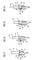
- the guide cam 28 acts in this case for positive guidance of the driver 25 with a guide web 29 (FIG 11 to 14) together, which is mounted on the inside on a guide portion 30 of the support frame 11 and therefore hidden in FIG.
- the actuating element 13 is inserted with a remote from the operating end 24 end 31 in a longitudinal guide 32 of the support frame 11 and is guided in this longitudinal guide 32 between two guide sleeves 33 and 34 slidably.
- the actuating element 13 is in this case biased by an inserted into a spring box 35 of the support frame 11 and cooperating with the end 31 compression spring 36 in a rest position and is elastically deflected from this rest position by applying pressure to the operating end 24 against the spring pressure.
- the actuating element 13 can be latched with the carrier frame 11 behind the guide sleeve 33 with a spring arm 37 which can be pressed elastically on the body 23.
- FIG. 2 shows the mounting position of the functional relay 1, in which the rocker 12 and the actuator 13 together Compression spring 36 are fixed to the support frame 11 and the reset mechanism 3 formed in this way is snapped onto the relay module 2.
- this mounting position acts, as is apparent from Figures 3 and 4, the shift lever 21 of the rocker 12 with the engagement 7 together by engaging through the housing opening 8 into the recess 10 of the switching mechanism 9 of the relay module 2 and the rocker 12 thus mechanically coupled with the switching mechanism 9.
- the pivot position of the rocker 12 is clearly correlated with the switching state of the relay module 2.
- the rocker 12 is always pivoted in a characteristic manner when switching the relay module 2 or switched on pivoting of the rocker 12 of the relay module 2.
- FIG 3 shows an on state of the relay module 2, which corresponds to a first pivot position 38 of the rocker 12, in which the leg 20 of the rocker 12 (as shown in FIG 2) approximately perpendicular to "up", i. approximately parallel with the body 23 of the actuating element 13, is aligned.
- An off position of the relay module 2 shown in FIG 4 corresponds to a second pivot position 39 of the rocker 12, in which the leg 20 (as in FIG 2 only indicated) is aligned obliquely with respect to the body 23 of the actuating element 13 and thus with respect to the pivoting position 38 to a Angle ⁇ is tilted.
- the actuator 13 is actuated in the manner of a push button.
- the driver 25 cooperates in a manner described in more detail below with a free end 40 of the leg 19, so that the rocker 12 is tilted from the pivot position 39 into the pivot position 38 and thereby the relay module 2 is switched.
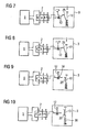
- FIGS. 5 shows the relay module 2, and thus the function relay 1 in the closed position, in which a switching connection between contacts K1 and K2 closed and another switching connection between contacts K3 and K4 is opened.
- an electromechanical trigger 41 of the relay module 2 is connected to the electronic trip circuit S constructed on the printed circuit board 4.
- the triggering circuit S is designed such that it outputs a trigger voltage U via the contacts A1 and A2 to the trigger 41 in an overload case.
- the trigger 41 converts the tripping voltage U into mechanical energy, which is transmitted by the trigger 41 to the switching mechanism 9 and causes a circuit of the relay module 2 in the off state shown in FIG 6 by the switching connection between the contacts K1 and K2 capped and the switching connection between the contacts K3 and K4 is closed. With the switching off of the relay module 2, the rocker 12 tilts from the pivoting position 38 into the pivoting position 39 (FIG. 6).
- the actuating element 13 is pressure-actuated according to FIG.
- the follower 25 is pivoted in such a way that it is mechanically coupled to the rocker 12 via a positive guidance described in more detail below, and this is swiveled back in the direction of the swivel position 38 with continued displacement of the actuating element 13 (FIG. 8).
- the rocker 12 as described above, causes a switching back of the relay module 2 in the ON state (FIG 8).
- the forced operation is designed such that the driver 25 is mechanically decoupled from the rocker 12 when the actuating element 13 (in an actuating position according to FIG. 9) is pushed completely and in this case the rocker 12 into the swivel position 38 is pivoted back.
- the mechanical decoupling of the driver 25 of the rocker 12 a free release of the functional relay 1 is achieved.
- the relay module 2 can again be put into the off state under the action of the tripping circuit S, even if the actuating element 13 is pressed at this time.
- the actuator 13 If the actuator 13 is relieved after the reset operation, it returns under the action of the compression spring 36 back to the idle state shown in FIG 10 back.
- the driver 25 follows in this decoupled from the rocker 12 state. As can be seen from a comparison of FIGS. 10 and 5, the initial state shown in FIG. 5 is thus restored.
- the described circular guide of the guide cam 28 around the guide web 29 around is achieved in particular by the fact that the guide web 29 and / or the guide cam 28 are provided on the abutting upon displacement of the actuating element 13 surfaces with corresponding Abgleitschrägen.
Landscapes
- Electromagnetism (AREA)
- Physics & Mathematics (AREA)
- Control Of Electric Motors In General (AREA)
- Revetment (AREA)
- Pharmaceuticals Containing Other Organic And Inorganic Compounds (AREA)
- Tumbler Switches (AREA)
- Switches With Compound Operations (AREA)
- Electronic Switches (AREA)
- Noodles (AREA)
- Switch Cases, Indication, And Locking (AREA)
- Arrangement Or Mounting Of Control Devices For Change-Speed Gearing (AREA)
- Connection Of Motors, Electrical Generators, Mechanical Devices, And The Like (AREA)
- Mechanisms For Operating Contacts (AREA)
Priority Applications (9)
| Application Number | Priority Date | Filing Date | Title |
|---|---|---|---|
| DE502005001834T DE502005001834D1 (de) | 2005-06-20 | 2005-06-20 | Elektronisches Funktionsrelais |
| PL05013266T PL1737007T3 (pl) | 2005-06-20 | 2005-06-20 | Elektroniczny przekaźnik funkcyjny |
| AT05013266T ATE377252T1 (de) | 2005-06-20 | 2005-06-20 | Elektronisches funktionsrelais |
| EP05013266A EP1737007B1 (de) | 2005-06-20 | 2005-06-20 | Elektronisches Funktionsrelais |
| ES05013266T ES2293426T3 (es) | 2005-06-20 | 2005-06-20 | Rele electronico de funcion. |
| DK05013266T DK1737007T3 (da) | 2005-06-20 | 2005-06-20 | Elektronisk funktionsrelæ |
| CNB2006100925987A CN100508098C (zh) | 2005-06-20 | 2006-06-16 | 电子功能继电器 |
| US11/454,039 US7317170B2 (en) | 2005-06-20 | 2006-06-16 | Electronic function relay |
| HK07102600.1A HK1096767B (en) | 2005-06-20 | 2007-03-09 | Electronic function relay |
Applications Claiming Priority (1)
| Application Number | Priority Date | Filing Date | Title |
|---|---|---|---|
| EP05013266A EP1737007B1 (de) | 2005-06-20 | 2005-06-20 | Elektronisches Funktionsrelais |
Publications (2)
| Publication Number | Publication Date |
|---|---|
| EP1737007A1 EP1737007A1 (de) | 2006-12-27 |
| EP1737007B1 true EP1737007B1 (de) | 2007-10-31 |
Family
ID=35149586
Family Applications (1)
| Application Number | Title | Priority Date | Filing Date |
|---|---|---|---|
| EP05013266A Expired - Lifetime EP1737007B1 (de) | 2005-06-20 | 2005-06-20 | Elektronisches Funktionsrelais |
Country Status (8)
| Country | Link |
|---|---|
| US (1) | US7317170B2 (da) |
| EP (1) | EP1737007B1 (da) |
| CN (1) | CN100508098C (da) |
| AT (1) | ATE377252T1 (da) |
| DE (1) | DE502005001834D1 (da) |
| DK (1) | DK1737007T3 (da) |
| ES (1) | ES2293426T3 (da) |
| PL (1) | PL1737007T3 (da) |
Families Citing this family (3)
| Publication number | Priority date | Publication date | Assignee | Title |
|---|---|---|---|---|
| US9159514B2 (en) * | 2013-11-18 | 2015-10-13 | Tyco Electronics Corporation | Relay connector assembly for a relay system |
| KR102292613B1 (ko) * | 2014-10-02 | 2021-08-23 | 에스케이이노베이션 주식회사 | 진단 기능을 포함하는 과충전 방지 장치 및 방법 |
| CN108335948A (zh) * | 2018-02-09 | 2018-07-27 | 钱斌彬 | 一种双稳态继电器 |
Family Cites Families (4)
| Publication number | Priority date | Publication date | Assignee | Title |
|---|---|---|---|---|
| DE69612771T2 (de) * | 1995-02-15 | 2002-04-18 | Matsushita Electric Works, Ltd. | Elektromagnetisches Relais |
| DE29803871U1 (de) * | 1998-03-05 | 1998-06-10 | Abb Patent Gmbh, 68309 Mannheim | Thermisches Überlastrelais |
| US6246558B1 (en) * | 1998-08-24 | 2001-06-12 | Leviton Manufacturing Company | Circuit interrupting device with reverse wiring protection |
| US7161104B2 (en) * | 2003-09-26 | 2007-01-09 | Rockwell Automation Technologies, Inc. | Trip-free PCB mountable relay configuration and method |
-
2005
- 2005-06-20 EP EP05013266A patent/EP1737007B1/de not_active Expired - Lifetime
- 2005-06-20 DE DE502005001834T patent/DE502005001834D1/de not_active Expired - Lifetime
- 2005-06-20 ES ES05013266T patent/ES2293426T3/es not_active Expired - Lifetime
- 2005-06-20 PL PL05013266T patent/PL1737007T3/pl unknown
- 2005-06-20 AT AT05013266T patent/ATE377252T1/de active
- 2005-06-20 DK DK05013266T patent/DK1737007T3/da active
-
2006
- 2006-06-16 CN CNB2006100925987A patent/CN100508098C/zh not_active Expired - Fee Related
- 2006-06-16 US US11/454,039 patent/US7317170B2/en active Active
Also Published As
| Publication number | Publication date |
|---|---|
| CN100508098C (zh) | 2009-07-01 |
| HK1096767A1 (zh) | 2007-06-08 |
| DE502005001834D1 (de) | 2007-12-13 |
| ATE377252T1 (de) | 2007-11-15 |
| US7317170B2 (en) | 2008-01-08 |
| US20070001799A1 (en) | 2007-01-04 |
| EP1737007A1 (de) | 2006-12-27 |
| PL1737007T3 (pl) | 2008-03-31 |
| DK1737007T3 (da) | 2008-02-11 |
| CN1885470A (zh) | 2006-12-27 |
| ES2293426T3 (es) | 2008-03-16 |
Similar Documents
| Publication | Publication Date | Title |
|---|---|---|
| EP0525137B1 (de) | Schutzschaltgerät zur differenzstrom- und unterspannungsauslösung | |
| EP1797577B1 (de) | Elektrischer schutzschalter mit schutzfunktion | |
| EP2656362B1 (de) | Arretierbarer elektrischer schalter | |
| EP0222181A1 (de) | Überstromschutzschalter | |
| EP0347592A1 (de) | Türverriegelungsvorrichtung für elektrische Geräte | |
| DE2747784A1 (de) | Elektrischer sicherheitstrennschalter | |
| EP2057653B1 (de) | Elektrischer schalter | |
| EP1880453A1 (de) | Anschluss- und basisteil zur aufnahme eines steckbaren überspannungsableiters | |
| EP0612089A2 (de) | Schaltvorrichtung für Leistungsschaltgeräte | |
| EP0049209B1 (de) | Schutzschalter kompakter Bauart mit einem Auslösestift | |
| EP0299291B1 (de) | Leitungsschutzschalter | |
| EP1737007A1 (de) | Elektronisches Funktionsrelais | |
| DE102010019741B4 (de) | Schaltmechanik für einen Fehlerstromschutzschalter sowie Fehlerstromschutzschalter | |
| EP2779196B1 (de) | Miniatur-Schutzschalter | |
| EP1173870B1 (de) | Koppelbare schutzschalteinrichtung | |
| DE4234065C1 (de) | Schaltgerät | |
| DE19745017A1 (de) | Elektrischer Schalter | |
| DE3639166C2 (da) | ||
| EP0310943B1 (de) | Elektrisches Schaltgerät | |
| DE19735413A1 (de) | Auslösevorrichtung für einen Schutzschalter | |
| DE10243597B4 (de) | Leistungsschalter | |
| EP0537700A1 (de) | Elektrisches Schaltgerät, insbesondere Wippenschalter für Haushaltsgeräte | |
| DE102022205306B3 (de) | Überspannungsschutzanordnungen | |
| DE19701470C1 (de) | Verklinkungseinrichtung für einen elektrischen Schalter | |
| DE102022204479B3 (de) | Adapter zur Montage von Zubehörteilen und elektrischer Schalter mit solch einem Adapter |
Legal Events
| Date | Code | Title | Description |
|---|---|---|---|
| PUAI | Public reference made under article 153(3) epc to a published international application that has entered the european phase |
Free format text: ORIGINAL CODE: 0009012 |
|
| 17P | Request for examination filed |
Effective date: 20060606 |
|
| AK | Designated contracting states |
Kind code of ref document: A1 Designated state(s): AT BE BG CH CY CZ DE DK EE ES FI FR GB GR HU IE IS IT LI LT LU MC NL PL PT RO SE SI SK TR |
|
| AX | Request for extension of the european patent |
Extension state: AL BA HR LV MK YU |
|
| GRAP | Despatch of communication of intention to grant a patent |
Free format text: ORIGINAL CODE: EPIDOSNIGR1 |
|
| GRAS | Grant fee paid |
Free format text: ORIGINAL CODE: EPIDOSNIGR3 |
|
| AKX | Designation fees paid |
Designated state(s): AT BE BG CH CY CZ DE DK EE ES FI FR GB GR HU IE IS IT LI LT LU MC NL PL PT RO SE SI SK TR |
|
| GRAA | (expected) grant |
Free format text: ORIGINAL CODE: 0009210 |
|
| AK | Designated contracting states |
Kind code of ref document: B1 Designated state(s): AT BE BG CH CY CZ DE DK EE ES FI FR GB GR HU IE IS IT LI LT LU MC NL PL PT RO SE SI SK TR |
|
| REG | Reference to a national code |
Ref country code: GB Ref legal event code: FG4D Free format text: NOT ENGLISH |
|
| REG | Reference to a national code |
Ref country code: IE Ref legal event code: FG4D Free format text: LANGUAGE OF EP DOCUMENT: GERMAN |
|
| REG | Reference to a national code |
Ref country code: CH Ref legal event code: EP |
|
| REF | Corresponds to: |
Ref document number: 502005001834 Country of ref document: DE Date of ref document: 20071213 Kind code of ref document: P |
|
| REG | Reference to a national code |
Ref country code: CH Ref legal event code: NV Representative=s name: SIEMENS SCHWEIZ AG |
|
| REG | Reference to a national code |
Ref country code: SE Ref legal event code: TRGR |
|
| GBT | Gb: translation of ep patent filed (gb section 77(6)(a)/1977) |
Effective date: 20080110 |
|
| REG | Reference to a national code |
Ref country code: DK Ref legal event code: T3 |
|
| REG | Reference to a national code |
Ref country code: ES Ref legal event code: FG2A Ref document number: 2293426 Country of ref document: ES Kind code of ref document: T3 |
|
| REG | Reference to a national code |
Ref country code: PL Ref legal event code: T3 |
|
| PG25 | Lapsed in a contracting state [announced via postgrant information from national office to epo] |
Ref country code: PT Free format text: LAPSE BECAUSE OF FAILURE TO SUBMIT A TRANSLATION OF THE DESCRIPTION OR TO PAY THE FEE WITHIN THE PRESCRIBED TIME-LIMIT Effective date: 20080331 Ref country code: LT Free format text: LAPSE BECAUSE OF FAILURE TO SUBMIT A TRANSLATION OF THE DESCRIPTION OR TO PAY THE FEE WITHIN THE PRESCRIBED TIME-LIMIT Effective date: 20071031 Ref country code: IS Free format text: LAPSE BECAUSE OF FAILURE TO SUBMIT A TRANSLATION OF THE DESCRIPTION OR TO PAY THE FEE WITHIN THE PRESCRIBED TIME-LIMIT Effective date: 20080229 Ref country code: SI Free format text: LAPSE BECAUSE OF FAILURE TO SUBMIT A TRANSLATION OF THE DESCRIPTION OR TO PAY THE FEE WITHIN THE PRESCRIBED TIME-LIMIT Effective date: 20071031 Ref country code: BG Free format text: LAPSE BECAUSE OF FAILURE TO SUBMIT A TRANSLATION OF THE DESCRIPTION OR TO PAY THE FEE WITHIN THE PRESCRIBED TIME-LIMIT Effective date: 20080131 |
|
| REG | Reference to a national code |
Ref country code: IE Ref legal event code: FD4D |
|
| ET | Fr: translation filed | ||
| PG25 | Lapsed in a contracting state [announced via postgrant information from national office to epo] |
Ref country code: SK Free format text: LAPSE BECAUSE OF FAILURE TO SUBMIT A TRANSLATION OF THE DESCRIPTION OR TO PAY THE FEE WITHIN THE PRESCRIBED TIME-LIMIT Effective date: 20071031 Ref country code: RO Free format text: LAPSE BECAUSE OF FAILURE TO SUBMIT A TRANSLATION OF THE DESCRIPTION OR TO PAY THE FEE WITHIN THE PRESCRIBED TIME-LIMIT Effective date: 20071031 |
|
| PLBE | No opposition filed within time limit |
Free format text: ORIGINAL CODE: 0009261 |
|
| STAA | Information on the status of an ep patent application or granted ep patent |
Free format text: STATUS: NO OPPOSITION FILED WITHIN TIME LIMIT |
|
| 26N | No opposition filed |
Effective date: 20080801 |
|
| PG25 | Lapsed in a contracting state [announced via postgrant information from national office to epo] |
Ref country code: IE Free format text: LAPSE BECAUSE OF FAILURE TO SUBMIT A TRANSLATION OF THE DESCRIPTION OR TO PAY THE FEE WITHIN THE PRESCRIBED TIME-LIMIT Effective date: 20071031 |
|
| PG25 | Lapsed in a contracting state [announced via postgrant information from national office to epo] |
Ref country code: MC Free format text: LAPSE BECAUSE OF NON-PAYMENT OF DUE FEES Effective date: 20080630 Ref country code: GR Free format text: LAPSE BECAUSE OF FAILURE TO SUBMIT A TRANSLATION OF THE DESCRIPTION OR TO PAY THE FEE WITHIN THE PRESCRIBED TIME-LIMIT Effective date: 20080201 |
|
| PG25 | Lapsed in a contracting state [announced via postgrant information from national office to epo] |
Ref country code: FI Free format text: LAPSE BECAUSE OF FAILURE TO SUBMIT A TRANSLATION OF THE DESCRIPTION OR TO PAY THE FEE WITHIN THE PRESCRIBED TIME-LIMIT Effective date: 20071031 |
|
| REG | Reference to a national code |
Ref country code: CH Ref legal event code: PCAR Free format text: SIEMENS SCHWEIZ AG;INTELLECTUAL PROPERTY FREILAGERSTRASSE 40;8047 ZUERICH (CH) |
|
| PG25 | Lapsed in a contracting state [announced via postgrant information from national office to epo] |
Ref country code: EE Free format text: LAPSE BECAUSE OF FAILURE TO SUBMIT A TRANSLATION OF THE DESCRIPTION OR TO PAY THE FEE WITHIN THE PRESCRIBED TIME-LIMIT Effective date: 20071031 |
|
| PG25 | Lapsed in a contracting state [announced via postgrant information from national office to epo] |
Ref country code: CY Free format text: LAPSE BECAUSE OF FAILURE TO SUBMIT A TRANSLATION OF THE DESCRIPTION OR TO PAY THE FEE WITHIN THE PRESCRIBED TIME-LIMIT Effective date: 20071031 |
|
| PG25 | Lapsed in a contracting state [announced via postgrant information from national office to epo] |
Ref country code: LU Free format text: LAPSE BECAUSE OF NON-PAYMENT OF DUE FEES Effective date: 20080620 Ref country code: HU Free format text: LAPSE BECAUSE OF FAILURE TO SUBMIT A TRANSLATION OF THE DESCRIPTION OR TO PAY THE FEE WITHIN THE PRESCRIBED TIME-LIMIT Effective date: 20080501 |
|
| PGFP | Annual fee paid to national office [announced via postgrant information from national office to epo] |
Ref country code: IT Payment date: 20120626 Year of fee payment: 8 |
|
| PG25 | Lapsed in a contracting state [announced via postgrant information from national office to epo] |
Ref country code: IT Free format text: LAPSE BECAUSE OF NON-PAYMENT OF DUE FEES Effective date: 20130620 |
|
| REG | Reference to a national code |
Ref country code: FR Ref legal event code: PLFP Year of fee payment: 12 |
|
| PGFP | Annual fee paid to national office [announced via postgrant information from national office to epo] |
Ref country code: CZ Payment date: 20160620 Year of fee payment: 12 Ref country code: GB Payment date: 20160610 Year of fee payment: 12 |
|
| PGFP | Annual fee paid to national office [announced via postgrant information from national office to epo] |
Ref country code: AT Payment date: 20160510 Year of fee payment: 12 Ref country code: DK Payment date: 20160620 Year of fee payment: 12 Ref country code: PL Payment date: 20160523 Year of fee payment: 12 Ref country code: BE Payment date: 20160620 Year of fee payment: 12 Ref country code: TR Payment date: 20160526 Year of fee payment: 12 Ref country code: NL Payment date: 20160602 Year of fee payment: 12 |
|
| PGFP | Annual fee paid to national office [announced via postgrant information from national office to epo] |
Ref country code: CH Payment date: 20160902 Year of fee payment: 12 |
|
| PGFP | Annual fee paid to national office [announced via postgrant information from national office to epo] |
Ref country code: ES Payment date: 20160726 Year of fee payment: 12 |
|
| REG | Reference to a national code |
Ref country code: FR Ref legal event code: PLFP Year of fee payment: 13 |
|
| REG | Reference to a national code |
Ref country code: CH Ref legal event code: PCOW Free format text: NEW ADDRESS: WERNER-VON-SIEMENS-STRASSE 1, 80333 MUENCHEN (DE) |
|
| REG | Reference to a national code |
Ref country code: DK Ref legal event code: EBP Effective date: 20170630 |
|
| PG25 | Lapsed in a contracting state [announced via postgrant information from national office to epo] |
Ref country code: CZ Free format text: LAPSE BECAUSE OF NON-PAYMENT OF DUE FEES Effective date: 20170620 |
|
| REG | Reference to a national code |
Ref country code: CH Ref legal event code: PL |
|
| REG | Reference to a national code |
Ref country code: NL Ref legal event code: MM Effective date: 20170701 |
|
| REG | Reference to a national code |
Ref country code: AT Ref legal event code: MM01 Ref document number: 377252 Country of ref document: AT Kind code of ref document: T Effective date: 20170620 |
|
| GBPC | Gb: european patent ceased through non-payment of renewal fee |
Effective date: 20170620 |
|
| PG25 | Lapsed in a contracting state [announced via postgrant information from national office to epo] |
Ref country code: NL Free format text: LAPSE BECAUSE OF NON-PAYMENT OF DUE FEES Effective date: 20170701 |
|
| PG25 | Lapsed in a contracting state [announced via postgrant information from national office to epo] |
Ref country code: GB Free format text: LAPSE BECAUSE OF NON-PAYMENT OF DUE FEES Effective date: 20170620 Ref country code: CH Free format text: LAPSE BECAUSE OF NON-PAYMENT OF DUE FEES Effective date: 20170630 Ref country code: LI Free format text: LAPSE BECAUSE OF NON-PAYMENT OF DUE FEES Effective date: 20170630 |
|
| PG25 | Lapsed in a contracting state [announced via postgrant information from national office to epo] |
Ref country code: AT Free format text: LAPSE BECAUSE OF NON-PAYMENT OF DUE FEES Effective date: 20170620 |
|
| REG | Reference to a national code |
Ref country code: FR Ref legal event code: PLFP Year of fee payment: 14 |
|
| REG | Reference to a national code |
Ref country code: BE Ref legal event code: MM Effective date: 20170630 |
|
| PG25 | Lapsed in a contracting state [announced via postgrant information from national office to epo] |
Ref country code: DK Free format text: LAPSE BECAUSE OF NON-PAYMENT OF DUE FEES Effective date: 20170630 |
|
| PG25 | Lapsed in a contracting state [announced via postgrant information from national office to epo] |
Ref country code: BE Free format text: LAPSE BECAUSE OF NON-PAYMENT OF DUE FEES Effective date: 20170630 |
|
| REG | Reference to a national code |
Ref country code: ES Ref legal event code: FD2A Effective date: 20181113 |
|
| PG25 | Lapsed in a contracting state [announced via postgrant information from national office to epo] |
Ref country code: PL Free format text: LAPSE BECAUSE OF NON-PAYMENT OF DUE FEES Effective date: 20170620 |
|
| PG25 | Lapsed in a contracting state [announced via postgrant information from national office to epo] |
Ref country code: ES Free format text: LAPSE BECAUSE OF NON-PAYMENT OF DUE FEES Effective date: 20170621 |
|
| PG25 | Lapsed in a contracting state [announced via postgrant information from national office to epo] |
Ref country code: TR Free format text: LAPSE BECAUSE OF NON-PAYMENT OF DUE FEES Effective date: 20170620 |
|
| P01 | Opt-out of the competence of the unified patent court (upc) registered |
Effective date: 20230510 |
|
| PGFP | Annual fee paid to national office [announced via postgrant information from national office to epo] |
Ref country code: FR Payment date: 20230619 Year of fee payment: 19 |
|
| PGFP | Annual fee paid to national office [announced via postgrant information from national office to epo] |
Ref country code: SE Payment date: 20230608 Year of fee payment: 19 |
|
| PGFP | Annual fee paid to national office [announced via postgrant information from national office to epo] |
Ref country code: DE Payment date: 20230818 Year of fee payment: 19 |
|
| REG | Reference to a national code |
Ref country code: DE Ref legal event code: R119 Ref document number: 502005001834 Country of ref document: DE |
|
| REG | Reference to a national code |
Ref country code: SE Ref legal event code: EUG |
|
| PG25 | Lapsed in a contracting state [announced via postgrant information from national office to epo] |
Ref country code: DE Free format text: LAPSE BECAUSE OF NON-PAYMENT OF DUE FEES Effective date: 20250101 |
|
| PG25 | Lapsed in a contracting state [announced via postgrant information from national office to epo] |
Ref country code: FR Free format text: LAPSE BECAUSE OF NON-PAYMENT OF DUE FEES Effective date: 20240630 |
|
| PG25 | Lapsed in a contracting state [announced via postgrant information from national office to epo] |
Ref country code: SE Free format text: LAPSE BECAUSE OF NON-PAYMENT OF DUE FEES Effective date: 20240621 |