EP1736334B1 - Vorrichtung zur antimikrobielen Behandlung durch Diffusion eines flüchtigen Behandlungsmittels insbesondere für eine Lüftungs-, Heizung- oder Klimaanlage eines Fahrzeuges - Google Patents
Vorrichtung zur antimikrobielen Behandlung durch Diffusion eines flüchtigen Behandlungsmittels insbesondere für eine Lüftungs-, Heizung- oder Klimaanlage eines Fahrzeuges Download PDFInfo
- Publication number
- EP1736334B1 EP1736334B1 EP06010217A EP06010217A EP1736334B1 EP 1736334 B1 EP1736334 B1 EP 1736334B1 EP 06010217 A EP06010217 A EP 06010217A EP 06010217 A EP06010217 A EP 06010217A EP 1736334 B1 EP1736334 B1 EP 1736334B1
- Authority
- EP
- European Patent Office
- Prior art keywords
- filter
- housing
- framework
- frame
- substrate
- Prior art date
- Legal status (The legal status is an assumption and is not a legal conclusion. Google has not performed a legal analysis and makes no representation as to the accuracy of the status listed.)
- Not-in-force
Links
Images


Classifications
-
- B—PERFORMING OPERATIONS; TRANSPORTING
- B60—VEHICLES IN GENERAL
- B60H—ARRANGEMENTS OF HEATING, COOLING, VENTILATING OR OTHER AIR-TREATING DEVICES SPECIALLY ADAPTED FOR PASSENGER OR GOODS SPACES OF VEHICLES
- B60H3/00—Other air-treating devices
- B60H3/0007—Adding substances other than water to the air, e.g. perfume, oxygen
- B60H3/0014—Adding substances other than water to the air, e.g. perfume, oxygen characterised by the location of the substance adding device
-
- B—PERFORMING OPERATIONS; TRANSPORTING
- B01—PHYSICAL OR CHEMICAL PROCESSES OR APPARATUS IN GENERAL
- B01D—SEPARATION
- B01D46/00—Filters or filtering processes specially modified for separating dispersed particles from gases or vapours
- B01D46/0027—Filters or filtering processes specially modified for separating dispersed particles from gases or vapours with additional separating or treating functions
- B01D46/0035—Filters or filtering processes specially modified for separating dispersed particles from gases or vapours with additional separating or treating functions by wetting, e.g. using surfaces covered with oil
-
- B—PERFORMING OPERATIONS; TRANSPORTING
- B60—VEHICLES IN GENERAL
- B60H—ARRANGEMENTS OF HEATING, COOLING, VENTILATING OR OTHER AIR-TREATING DEVICES SPECIALLY ADAPTED FOR PASSENGER OR GOODS SPACES OF VEHICLES
- B60H3/00—Other air-treating devices
- B60H3/0007—Adding substances other than water to the air, e.g. perfume, oxygen
-
- B—PERFORMING OPERATIONS; TRANSPORTING
- B60—VEHICLES IN GENERAL
- B60H—ARRANGEMENTS OF HEATING, COOLING, VENTILATING OR OTHER AIR-TREATING DEVICES SPECIALLY ADAPTED FOR PASSENGER OR GOODS SPACES OF VEHICLES
- B60H3/00—Other air-treating devices
- B60H3/0085—Smell or pollution preventing arrangements
-
- B—PERFORMING OPERATIONS; TRANSPORTING
- B60—VEHICLES IN GENERAL
- B60H—ARRANGEMENTS OF HEATING, COOLING, VENTILATING OR OTHER AIR-TREATING DEVICES SPECIALLY ADAPTED FOR PASSENGER OR GOODS SPACES OF VEHICLES
- B60H3/00—Other air-treating devices
- B60H3/06—Filtering
-
- B—PERFORMING OPERATIONS; TRANSPORTING
- B60—VEHICLES IN GENERAL
- B60H—ARRANGEMENTS OF HEATING, COOLING, VENTILATING OR OTHER AIR-TREATING DEVICES SPECIALLY ADAPTED FOR PASSENGER OR GOODS SPACES OF VEHICLES
- B60H1/00—Heating, cooling or ventilating [HVAC] devices
- B60H1/00507—Details, e.g. mounting arrangements, desaeration devices
- B60H2001/00621—Fastening lids on air-conditioning housings
Definitions
- the invention is in the field of ventilation, heating and / or air conditioning, in particular vehicle interior. It relates to an air treatment device against a development of microorganisms within such a plant, by diffusion of a volatile agent treating.
- US 2003/0186643 discloses a device according to the preamble of the first claim.
- Such odors are in particular caused by the adsorption and desorption phenomena of gaseous pollutants, and by the aforementioned development of microorganisms.
- such an installation should not be made to the detriment of the size of the installation, desired the smallest possible, or be a source of a significant additional cost.
- this implementation is not carried out against a faculty offered standardization of the installation, while taking into account a modularity in the choice of the implementation or not of the device antimicrobial treatment, from the integration of the installation during the actual design of the vehicle, and / or during a first ride of the vehicle, and / or during a subsequent maintenance operation thereof.
- the object of the present invention is to provide an antimicrobial treatment device by diffusion of a volatile treating agent for a ventilation system, heating and / or air conditioning, including a vehicle. It is more particularly the object of the present invention to provide such a device which induces a limited increase in the size of the installation, and which allows a standardization of this installation while offering the ability to set up or not the device according to the choice of the manufacturer, and / or during a first ride of the vehicle, and / or during a subsequent maintenance operation of the latter and / or the installation.
- the subject of the present invention is an antimicrobial treatment device by diffusion of a volatile treating agent for a ventilation, heating and / or air conditioning installation, of a vehicle in particular.
- a cabin air filter consisting of a frame carrying a filter media.
- Such an air filter is for example a particulate filter, a combined filter, a activated carbon filter, a photocatalytic filter, a plasma filter, an electrostatic filter or any other similar filter.
- the filter comprises at least one means for integrating a carrier substrate of the treating agent.
- the substrate is for example a wick or the like impregnated with the treating agent, or a sachet containing a gel or the like.
- the substrate is likely to consist of any carrier member of the treating agent, the latter being a volatile agent diffusing through said member for the application of the treatment.
- the filter is capable of being equipped with one or more integration means of a said substrate.
- said integration means it is advantageously constituted by a receiving housing of the substrate formed in the frame of the filter.
- the housing is in particular formed on the frame of the filter extending along at least one of the dimensions of the latter. More particularly, the housing is likely to extend parallel and / or perpendicularly and / or transversely to the extension of the folds that comprises the filter medium.
- the frame is particularly shaped frame.
- a frame is for example composed of longitudinal members and / or sleepers supporting the filter media.
- the frame is formed of at least one overmolded wall (injection of the edges of the frame in the liquid state around the filter medium), glued (fixing the filter media on the edges of a frame previously molded by means of an adhesive) or welded (assembly of the frame and the filter medium in the form of finished parts).
- these walls extend on the periphery of the media.
- the housing is preferably formed inside one of the edges of the frame. According to another embodiment, the housing is likely to be formed between two opposite edges of the frame, such as in a central zone of the latter.
- the frame being provided with a hatch for closing a filter introducing passage inside the installation, the housing is for example formed in said hatch.
- said integration means is constituted by a container secured to the frame so as to form with the filter unitary piece, such as by welding, gluing or riveting.
- This container comprises a housing for receiving the substrate.
- the frame being shaped as a frame, the container is preferably attached laterally to an edge of the frame, the latter possibly being provided with a chute for receiving the container.
- the container is also likely to be attached to the frame by overmolding.
- a step specifically consists of returning material by molding on the frame of the filter to form the container.
- it is formed on the filter during the same molding operation. More particularly, the container is molded together with the frame of the filter.
- the container comprises at least two zones in axial extension, one in which is formed the housing and the other forming an extension body of the container along the entire wall corresponding frame, to avoid the formation of a non filtration area of the air flow.
- connection means with the filter.
- a cap is likely to be standard for any filter.
- the connecting means of the plug with the filter are reversible connection means or irreversible connection means. More in particular, the connection between the plug and the filter can be made reversibly, such as by screwing, by means of fasteners, such as screws or clips, by flexible interlocking, or irreversibly by welding, by gluing or by interlocking force.
- the cap is likely to be attached to the filter by a retaining member, for example by means of a flexible hinge, a link or similar retaining member.
- the plug is secured to an intermediate cartridge housing the substrate.
- the stopper is incidentally provided with a perforating striker of a sealing cap of the housing.
- the substrate is for example housed inside a container which is advantageously provided with said lid. According to other variants, this operculum is formed at the end of the substrate, or is formed inside the housing that includes the filter for receiving the substrate. If appropriate where the substrate is housed in the intermediate cartridge or a similar container, said seal is likely to be formed at the outlet of the cartridge or container.
- the connecting means of the plug with the frame are two-position connection means between which the plug is mounted to move on the frame, one waiting wherein the striker is remote from the cap, the other activation in which the striker perforates the cap to release the emission of the volatile agent treating.
- the installation is equipped with a device for treating air by volatile agent, without the congestion of this installation being considerably increased, with a limited reduction of the filtration surface.
- the housing and / or the container are susceptible to be arranged in the volume of a standard size filter, without significantly reducing the filtration area. If appropriate, in the case where the contribution of the housing and / or the container to the frame of the filter induces an increase in the standard volume of the filter, a reception clearance of the volume of this increase is likely to be provided in the wall of the installation, to avoid a reduction of the filtering surface of the filter, as small as it is.
- the present invention also relates to a ventilation system, heating and / or air conditioning equipped with an air treatment device that it conveys from a volatile treating agent.
- an installation comprises in particular at least one filter which incorporates means for integrating a carrier substrate of the treating agent.
- the filter is indifferently placed upstream and / or downstream of an evaporator that includes the installation.
- the filter is housed inside a housing which also houses functional members of the installation, such as an evaporator and a blower generating the air flow.
- the filter is housed in a housing which is assigned to it, and is placed under the awning of the vehicle to be accessible from the engine compartment.
- Such an awning is formed in particular of a receptacle formed in the upper zone of the apron separating the cockpit from the engine compartment, at the foot of the windshield.
- a filter (1) of a ventilation system, heating and / or air conditioning, including a vehicle mainly consists of a frame (2) shaped frame supporting a filter media (3).
- a housing (4) is provided inside one of the edges of the framework (2), for receiving a substrate (5), such as a wick or the like, impregnated with a treating agent volatile.
- the substrate is for example formed of a spongy cohesive body.
- This body is for example constituted of a mass capable of being formed from textile material, such as natural or artificial mixed textile fibers, from a mass of cellulose, such as a thick blotter pad of the type formed. of a touch or a wick, from a body formed of a mineral or vegetable substrate, possibly parcellized and compressed, from a cohesive mass of polymer powder, or even from a material of animal origin such as a porous leather.
- this material is likely to be wool, cotton, synthetic microfibers such as polypropylene, or any other natural or artificial textile material.
- this material is likely to be a cellulose wadding, white wood such as fir or pine, brown, compressed sawdust, peat moss or other similar plant material.
- the spongy cohesive body is a mineral material
- this material is likely to be montmorillonite, attapulgite, an earthy mixture such as cellulose mixed with kaolin, calcined diatomaceous earth magnesia, lime, metal oxides such as iron or aluminum, silicates, vermiculite, activated charcoal, silica, kieselguhr or other similar mineral.
- the substrate is also likely to be formed of a permeable sachet containing the treating agent in the liquid state or in the gel state.
- the treating agent is an antimicrobial and / or fungicidal and / or odorous and / or disinfecting agent, such as allyl-isothiocynate or analogous treatment agent.
- the outlet of the housing (4) is closed by a plug (6), which is attached to the frame (2) reversibly or irreversibly as will be described later.
- the integration of such a housing (4) on the filter (1), and in particular on the frame (2) of the latter, makes it possible to give the filter (1) a standardized structure for a any installation, nevertheless offering the faculty of setting up or not the substrate (5) in the integration means that the filter has for this purpose.
- the placing of the substrate (5) can be carried out on demand, for example according to the wishes of a vehicle manufacturer, and / or during an initial assembly and / or subsequently during a maintenance operation of the vehicle. installation and / or vehicle. More particularly, the filter (1) can be used in the same configuration of the installation, with or without the substrate (5).
- the latter can be in the form of a standard packaging for all the filters (1), with the advantage of a reduction in production costs due to a large volume of production of such filters (1) and standardized substrates (5).
- the integration of the substrate (5) on the filter (1), inside a housing (4) that it comprises allows such integration without the use of inserts, such as a cartridge housing the substrate (5).
- the latter is preferably disposed on the frame (2) out of the passage of the air flow, or at least in a region of the framework (2) normally full, so that the integration of the substrate (5) n induces no aeraulic loss.
- the means for integrating the substrate (5) on the filter (1) is organized for a diffusion of the treating agent corresponding to a daily quantity of deposit.
- the housing (4) is dimensioned inside the filter (1) to obtain such a diffusion.
- the permeable wall of the filter (1) through which the treating agent is diffused is a wall formed of polypropylene containing talc at 20%, having a thickness of about 0.9 mm +/- 10% and for an overall surface of the housing of the order of 4200 mm 2 +/- 10%.
- Such provisions make it possible to obtain a daily diffusion of the treating agent of the order of 45 mg at 40 ° C.
- the housing is also capable of being sized to provide a thickness of material through the wall of the frame and / or container secured thereto, for a daily diffusion of between 5 mg and 50 mg at 30 ° C. Preferably, this diffusion is of the order of 18 mg per day +/- 10%.
- the housing (4) is formed inside a lateral edge of the framework (2), while on the fig.2 , the housing (4) is formed inside a longitudinal edge of the frame (2).
- the housing (4) may be provided on the frame (2) in an orientation corresponding to at least one of the dimensions of this frame (2). More particularly, the housing (4) can be arranged in an orientation A parallel to a lateral edge of the framework (2), and / or in an orientation B parallel to a longitudinal edge of the framework (2) , and / or in an orientation C inclined relative to the general plane of the frame (2).
- the housing (4) may be arranged at the edge of the framework (2) to prevent pressure drop of the air flow passing through the filtering medium (3), or be formed in a central zone of the filter (1). ) to promote a more homogeneous diffusion of the treating agent on the evaporator of the installation.
- the outlet of the housing (4) can be arranged on any face of the filter (1), being oriented in any dimension of the framework for the introduction of the substrate (5) according to one of these dimensions.
- the housing (4) is formed in the framework (2) parallel to the folds of the filter media (3).
- the substrate (5) is placed inside an intermediate cartridge (7) provided with the plug (6) for closing the outlet of the housing (4).
- the filter (1) is introduced inside the installation through a passage formed in a wall (8) of the latter, which is closed by a filter access hatch (9), independent of this last.
- This intermediate cartridge (7) is particularly permeable to allow the diffusion of the volatile agent according to the daily quantities of deposit.
- the frame (2) integrates the hatch (9) for closing the passage in the wall (8) of the installation for the passage and installation of the filter (1).
- the housing (4) for receiving the substrate (5) is formed inside the hatch (9), and is closed off by an independent plug (6) reversibly or irreversibly connected to the hatch (9).
- the frame (2) and the hatch (9) preferably form a unitary piece, the replacement of the filter (1) being effected by a global replacement of said unitary piece.
- the plug (6) is used to close the outlet of the housing (4), which preferably directly receives the substrate (5).
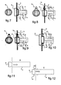
- the housing (4) is formed in the framework (2), on which the plug (6) is connected in a reversible manner, as shown in the fig.7 to fig.9 , irreversibly as shown on the fig.10 to fig.12 .
- the plug (6) is attached to the frame (2) by screwing.
- the plug (6) is attached to the frame (2) by means of a screw (25) passing through a tongue (10) that includes the plug (6).
- the plug (6) is attached to the frame (2) via an engagement pin (11) formed on a tongue (12) that comprises the plug (6).
- a device with pins (13) of connection quarter advantageously the fixing of the plug (6) on the frame (2).
- the plug (6) is attached to the frame (2) by irreversible engagement.
- the plug (6) is attached to the frame (2) by means of clips (14).
- the plug (6) is attached to the frame (2) by interlocking force.
- the plug (6) is attached to the frame (2) irreversibly by gluing.
- the housing (4) for receiving the substrate (5) is embodied by a container (15) attached to the framework (2), bordering one of the sides of the latter, a lateral side on the exemplary embodiments illustrated .
- the frame (2) comprises a chute (16) for receiving the container (15).
- the container (15) is attached to the frame by molding, or even being formed by molding therewith to form a unitary piece.
- said chute (16) is materialized by the last fold of the filter medium, which is folded so as to conform to the chute (16).
- the container (15) is preferably of a size corresponding to that of the side of the frame (2) on which it is arranged, to limit the non-filtration zone of the air flowing through the installation.
- the housing (4) for receiving the substrate (5) is formed inside a container (15) intended to be secured to the filter (1).
- This container (15) comprises the housing (4) for receiving the substrate (5).
- the plug (6) closing the outlet of the housing (4) is provided with a striker (18) for perforating a seal (19) closing the outlet of the housing (4).
- the plug (6) is mounted movably on the container (15), between a waiting position in which the striker (18) is kept away from the cover (19), and an activation position in which the operculum (19) is perforated.
- the cap (6) on the container comprise cooperating interlocking members (20,21), such as grooves and lips.
- the passage of the plug (6) from one position to the other occurs by pushing, to cause its axial displacement and the passage of a lip at least from a first groove to another axially offset groove.
- Other variants of mounting the cap (6) on the container (15) between its two positions of waiting and activation are likely to be implemented.
- the cover (19) may be formed at the end of an intermediate cartridge (22) housing the substrate (5) and introduced into the housing (4), as in the illustrated embodiment. According to other non shown, the lid (19) is formed directly on the container (15), being reported or formed in conjunction therewith, or is formed at the end of the substrate (5).
- the plug (6) is likely to be directly attached to the frame (2) of the filter (1) which comprises a housing (4) for receiving the substrate (5), as in the variants previously illustrated.
- the container (15) may be formed of a cartridge or the like secured to the media (3) of the filter (1).
- the substrate (5) is housed inside a first axial zone (23) of the container (15).
- This first zone (23) is extended by a second axial zone (24), which forms an extension body of the container (15) along the whole of the corresponding wall of the framework (2), to avoid the formation a zone of absence of filtration of the air flow.
- the second axial zone (24) is preferably permeable to allow diffusion of the treating agent therethrough, and allow homogeneous diffusion of the treating agent within the entire container (15).
- the permeability of the second axial zone (24) allows in particular by propagation of the treating agent from the end of the container (15) comprising the plug (6) to its opposite end.
Landscapes
- Engineering & Computer Science (AREA)
- Mechanical Engineering (AREA)
- Chemical & Material Sciences (AREA)
- Oil, Petroleum & Natural Gas (AREA)
- Chemical Kinetics & Catalysis (AREA)
- Life Sciences & Earth Sciences (AREA)
- Atmospheric Sciences (AREA)
- Environmental & Geological Engineering (AREA)
- Disinfection, Sterilisation Or Deodorisation Of Air (AREA)
- Air-Conditioning For Vehicles (AREA)
- Agricultural Chemicals And Associated Chemicals (AREA)
- Filtering Of Dispersed Particles In Gases (AREA)
Claims (22)
- Vorrichtung zur antimikrobiellen Behandlung durch Diffusion eines flüchtigen Behandlungsmittels für eine Belüftungs-, Heiz- und/oder Klimaanlage, mit einem Fahrgastraum-Luftfilter (1), der aus einem ein Filtermedium (3) tragenden Gerüst (2) besteht, wobei der Filter (1) mindestens ein Mittel zum Einbau eines das Behandlungsmittel tragenden Substrats (5) aufweist, wobei das Einbaumittel aus einem Fach (4) zur Aufnahme des Substrats (5) besteht, das im Gerüst (2) des Filters (1) angeordnet ist, dadurch gekennzeichnet, dass das Fach (4) von einem Deckel (6) verschlossen wird, der mit Verbindungsmitteln mit dem Filter (1) versehen ist.
- Vorrichtung nach Anspruch 1, dadurch gekennzeichnet, dass das Fach (4) auf dem Gerüst. (2) im Wesentlichen gemäß mindestens einer von dessen Abmessungen verlaufend angeordnet ist.
- Vorrichtung nach einem der Ansprüche 1 und 2, dadurch gekennzeichnet, dass, wenn das Gerüst (2) als Rahmen ausgebildet ist, das Fach (4) im Inneren eines der Ränder des Rahmens angeordnet ist.
- Vorrichtung nach einem der Ansprüche 1 und 2, dadurch gekennzeichnet, dass, wenn das Gerüst (2) als Rahmen ausgebildet ist, das Fach (4) zwischen zwei gegenüberliegenden Rändern des Rahmens angeordnet ist.
- Vorrichtung nach einem der Ansprüche 1 und 2, dadurch gekennzeichnet, dass, wenn das Gerüst (2) mit einer Verschlussklappe (9) eines Einführdurchgangs des Filters (1) ins Innere der Anlage versehen ist, das Fach (4) in der Klappe (9) angeordnet ist.
- Vorrichtung nach Anspruch 1, dadurch gekennzeichnet, dass das Einbaumittel aus einem Behälter (15) besteht, der fest mit dem Gerüst (2) verbunden wird, um mit dem Filter ein einheitliches Bauteil zu bilden, und der ein Fach (4) zur Aufnahme des Substrats aufweist.
- Vorrichtung nach Anspruch 6, dadurch gekennzeichnet, dass, wenn das Gerüst (2) als Rahmen ausgebildet ist, der Behälter (15) seitlich an einen Rand des Rahmens angesetzt ist.
- Vorrichtung nach Anspruch 7, dadurch gekennzeichnet, dass der Rand des Rahmens mit einer Aufnahmerinne (16) für den Behälter (15) versehen ist.
- Vorrichtung nach einem der Ansprüche 6 bis 8, dadurch gekennzeichnet, dass der Behälter (15) in Verbindung mit dem Gerüst (2) durch Formen angeordnet wird.
- Vorrichtung nach einem der Ansprüche 6 bis 9, dadurch gekennzeichnet, dass der Behälter (15) mindestens zwei Zonen in axialer Verlängerung aufweist, von denen in einer (23) das Fach (4) angeordnet ist und die andere (24) einen Verlängerungskörper des Behälters (15) entlang der ganzen entsprechenden Wand des Gerüsts (2) bildet, um die Bildung einer Zone der Nicht-Filterung des Luftstroms zu verhindern.
- Vorrichtung nach Anspruch 1, dadurch gekennzeichnet, dass die Verbindungsmittel des Deckels (6) mit dem Filter (1) Mittel zur umkehrbaren Verbindung sind.
- Vorrichtung nach Anspruch 1, dadurch gekennzeichnet, dass die Verbindungsmittel des Deckels (6) mit dem Filter (1) Mittel zur unumkehrbaren Verbindung sind.
- Vorrichtung nach einem der Ansprüche 1, 11, 12, dadurch gekennzeichnet, dass der Deckel (6) fest mit einer Zwischenpatrone (7) verbunden ist, in der das Substrat (5) untergebracht ist.
- Vorrichtung nach einem der Ansprüche 1, 11 bis 13, dadurch gekennzeichnet, dass der Deckel (6) mit einem Einstechteil (18) zum Durchstoßen einer Abdeckung (19) zum Abdichten des Fachs (4) versehen ist.
- Vorrichtung nach Anspruch 14, dadurch gekennzeichnet, dass, wenn das Substrat (5) im Inneren eines Behälters (15) untergebracht ist, dieser mit der Abdeckung (19) versehen ist.
- Vorrichtung nach Anspruch 14, dadurch gekennzeichnet, dass die Abdeckung (19) am Ende des Substrats (5) angeordnet ist.
- Vorrichtung nach Anspruch 14, dadurch gekennzeichnet, dass die Abdeckung (19) im Inneren des Fachs (4) angeordnet ist, das der Filter (1) zur Aufnahme des Substrats (5) aufweist.
- Vorrichtung nach einem der Ansprüche 1, 11 bis 17, dadurch gekennzeichnet, dass die Verbindungsmittel des Deckels (6) mit dem Gerüst (2) Verbindungsmittel mit zwei Stellungen sind, zwischen denen der Deckel (6) auf dem Gerüst (2) beweglich montiert ist, die eine eine Wartestellung, in der das Einstechteil (18) von der Abdeckung (19) entfernt ist, die andere eine Aktivierungsstellung, in der das Einstechteil (18) die Abdeckung (19) durchbohrt, um die Ausgabe des flüchtigen Behandlungsmittels freizugeben.
- Belüftungs-, Heiz- und/oder Klimaanlage, die eine Vorrichtung zur antimikrobiellen Behandlung nach einem der vorhergehenden Ansprüche enthält.
- Anlage nach Anspruch 19, dadurch gekennzeichnet, dass der Filter (1) beliebig vor und/oder hinter einem Verdampfer angeordnet ist, den die Anlage aufweist.
- Anlage nach einem der Ansprüche 19 und 20, dadurch gekennzeichnet, dass der Filter im Inneren eines Gehäuses untergebracht ist, in dem außerdem Funktionsorgane der Anlage untergebracht sind.
- Anlage nach einem der Ansprüche 19 und 20, dadurch gekennzeichnet, dass der Filter im Inneren eines ihm zugewiesenen Gehäuses untergebracht ist und sich unter dem Luftschlitz des Fahrzeugs befindet, um vom Motorraum aus zugänglich zu sein.
Applications Claiming Priority (1)
| Application Number | Priority Date | Filing Date | Title |
|---|---|---|---|
| FR0506352A FR2887616B1 (fr) | 2005-06-22 | 2005-06-22 | Dispositif de traitement antimicrobien par diffusion d'un agent traitant volatil pour une installation de ventilation, de chauffage et/ou de climatisation, d'un vehicule notamment |
Publications (2)
| Publication Number | Publication Date |
|---|---|
| EP1736334A1 EP1736334A1 (de) | 2006-12-27 |
| EP1736334B1 true EP1736334B1 (de) | 2010-03-31 |
Family
ID=35735053
Family Applications (1)
| Application Number | Title | Priority Date | Filing Date |
|---|---|---|---|
| EP06010217A Not-in-force EP1736334B1 (de) | 2005-06-22 | 2006-05-18 | Vorrichtung zur antimikrobielen Behandlung durch Diffusion eines flüchtigen Behandlungsmittels insbesondere für eine Lüftungs-, Heizung- oder Klimaanlage eines Fahrzeuges |
Country Status (7)
| Country | Link |
|---|---|
| US (1) | US7670413B2 (de) |
| EP (1) | EP1736334B1 (de) |
| CN (1) | CN1883973A (de) |
| AT (1) | ATE462592T1 (de) |
| DE (1) | DE602006013224D1 (de) |
| ES (1) | ES2341985T3 (de) |
| FR (1) | FR2887616B1 (de) |
Families Citing this family (4)
| Publication number | Priority date | Publication date | Assignee | Title |
|---|---|---|---|---|
| US20090078121A1 (en) * | 2007-09-26 | 2009-03-26 | Helena Hepburn | Air supply vent filter for air conditioning systems |
| FR2945984A1 (fr) * | 2009-05-29 | 2010-12-03 | Peugeot Citroen Automobiles Sa | Dispositif de filtration d'air a compartiment(s) de rangement d'objet(s), pour un vehicule |
| JP2015217750A (ja) * | 2014-05-15 | 2015-12-07 | 株式会社デンソー | 車両用空調装置の通風ユニット |
| FR3063681A1 (fr) * | 2017-03-08 | 2018-09-14 | Valeo Systemes Thermiques | Dispositif d'immobilisation d'une cartouche dans un boitier, boitier comprenant ledit dispositif et ensemble dudit boitier et de ladite cartouche |
Citations (2)
| Publication number | Priority date | Publication date | Assignee | Title |
|---|---|---|---|---|
| US6029901A (en) * | 1998-11-19 | 2000-02-29 | Toy, Ii; John S. | Air freshener dispenser |
| DE202004010015U1 (de) * | 2004-06-25 | 2004-10-28 | Trw Automotive Electronics & Components Gmbh & Co.Kg | Luftverbesserungsvorrichtung zur Verwendung in Kraftfahrzeugen und Kartusche für die Luftverbesserungsvorrichtung |
Family Cites Families (27)
| Publication number | Priority date | Publication date | Assignee | Title |
|---|---|---|---|---|
| US3017239A (en) * | 1958-11-03 | 1962-01-16 | Fram Corp | Air conditioner filters having germicidal properties |
| US5240484A (en) * | 1987-07-21 | 1993-08-31 | Southwest Manufacturers & Distributors, Inc. | Antimicrobial vacuum cleaner bag |
| US4959087A (en) * | 1989-06-14 | 1990-09-25 | James Kappernaros | Air conditioning system filter with variable rate scent release |
| US5874052A (en) * | 1992-05-15 | 1999-02-23 | Medtek Devices, Inc. | Antimicrobial filter for use in electrocautery or laser surgery |
| US5258051A (en) * | 1992-09-21 | 1993-11-02 | Anderson Phillip T | Scented air filter |
| JPH08238307A (ja) * | 1995-03-06 | 1996-09-17 | Suntory Ltd | 除菌フィルターと無菌室の無菌化維持装置 |
| JP2001248852A (ja) * | 2000-03-06 | 2001-09-14 | Matsushita Electric Ind Co Ltd | 空調装置 |
| FR2807973B1 (fr) * | 2000-04-21 | 2002-11-15 | Filtrauto | Filtre a air d'habitacle de vehicule, vehicule comportant un tel filtre, et procede de fabrication |
| GB0017058D0 (en) * | 2000-07-11 | 2000-08-30 | Hall Vantage Limited | Purification of air |
| FR2815294B1 (fr) * | 2000-10-17 | 2003-07-18 | Valeo Climatisation | Dispositif de chauffage et de climatisation comportant des moyens d'odorisation de l'habitacle d' un vehicule |
| FR2824298B1 (fr) * | 2001-05-04 | 2003-12-12 | Valeo Climatisation | Dispositif de recyclage de l'air d'un habitacle de vehicule |
| US20030097936A1 (en) * | 2001-11-27 | 2003-05-29 | Robert Maleeny | Air scenting compositions and processes for use thereof in air scenting devices |
| US20030021721A1 (en) * | 2002-07-16 | 2003-01-30 | Microgenix Limited | Purification of air |
| JP4803653B2 (ja) * | 2003-04-23 | 2011-10-26 | 独立行政法人産業技術総合研究所 | 可視光応答型3次元微細セル構造光触媒フィルター及びその製造方法並びに浄化装置 |
| AU2003262668A1 (en) * | 2003-04-28 | 2004-11-23 | Ashland Inc. | Vehicle cabin air filter freshener |
| JP4283613B2 (ja) * | 2003-07-24 | 2009-06-24 | 株式会社ヴァレオサーマルシステムズ | 空気調和機及び抗菌剤入りケース |
| US20050042147A1 (en) * | 2003-08-21 | 2005-02-24 | Rees Wendy Nan | Package containing a scented and custom treated card |
| US20050079113A1 (en) * | 2003-10-09 | 2005-04-14 | Selander Raymond K. | Fan-driven air freshener |
| TWI301070B (en) * | 2004-01-13 | 2008-09-21 | Jong J Huang | Personal inhalation filter |
| WO2005079875A1 (en) * | 2004-02-24 | 2005-09-01 | Givaudan Sa | Air purifier and volatile liquid disseminator |
| US7118608B2 (en) * | 2004-04-12 | 2006-10-10 | Lovell William S | Self-powered, wearable personal air purifier |
| FR2873954B1 (fr) * | 2004-08-03 | 2009-02-27 | Valeo Climatisation Sa | Module de ventilation d'air pour un habitacle de vehicule |
| JP2008520395A (ja) * | 2004-11-23 | 2008-06-19 | エス.シー. ジョンソン アンド サン、インコーポレイテッド | 芳香付与と共に空気浄化を提供するシステムおよび方法 |
| FR2879103B1 (fr) * | 2004-12-09 | 2007-03-02 | Valeo Climatisation Sa | Conteneur permeable recevant un agent volatil de traitement d'air, pour notamment une installation de ventilation, de chauffage et/ou de climatisation d'un vehicule. |
| WO2006112005A1 (ja) * | 2005-04-12 | 2006-10-26 | Valeo Thermal Systems Japan Corporation | 揮発性物質の包装体及びその包装体を備えた車両空調装置 |
| US8343247B2 (en) * | 2005-09-09 | 2013-01-01 | Dexwet Usa Llc | Filter module |
| US8303693B2 (en) * | 2007-04-26 | 2012-11-06 | The Hong Kong Polytechnic University | Nanofiber filter facemasks and cabin filters |
-
2005
- 2005-06-22 FR FR0506352A patent/FR2887616B1/fr not_active Expired - Fee Related
-
2006
- 2006-05-18 AT AT06010217T patent/ATE462592T1/de not_active IP Right Cessation
- 2006-05-18 ES ES06010217T patent/ES2341985T3/es active Active
- 2006-05-18 EP EP06010217A patent/EP1736334B1/de not_active Not-in-force
- 2006-05-18 DE DE602006013224T patent/DE602006013224D1/de active Active
- 2006-06-19 US US11/455,475 patent/US7670413B2/en not_active Expired - Fee Related
- 2006-06-21 CN CNA2006100946038A patent/CN1883973A/zh active Pending
Patent Citations (2)
| Publication number | Priority date | Publication date | Assignee | Title |
|---|---|---|---|---|
| US6029901A (en) * | 1998-11-19 | 2000-02-29 | Toy, Ii; John S. | Air freshener dispenser |
| DE202004010015U1 (de) * | 2004-06-25 | 2004-10-28 | Trw Automotive Electronics & Components Gmbh & Co.Kg | Luftverbesserungsvorrichtung zur Verwendung in Kraftfahrzeugen und Kartusche für die Luftverbesserungsvorrichtung |
Also Published As
| Publication number | Publication date |
|---|---|
| US7670413B2 (en) | 2010-03-02 |
| CN1883973A (zh) | 2006-12-27 |
| EP1736334A1 (de) | 2006-12-27 |
| US20070006736A1 (en) | 2007-01-11 |
| ES2341985T3 (es) | 2010-06-30 |
| DE602006013224D1 (de) | 2010-05-12 |
| FR2887616B1 (fr) | 2013-03-01 |
| FR2887616A1 (fr) | 2006-12-29 |
| ATE462592T1 (de) | 2010-04-15 |
Similar Documents
| Publication | Publication Date | Title |
|---|---|---|
| EP1768864B1 (de) | Luftbehandlungsvorrichtung für einen partikelfilter einer heiz-, belüftungs- und/oder klimaanlage für einen fahrzeugfahrgastraum | |
| EP1736334B1 (de) | Vorrichtung zur antimikrobielen Behandlung durch Diffusion eines flüchtigen Behandlungsmittels insbesondere für eine Lüftungs-, Heizung- oder Klimaanlage eines Fahrzeuges | |
| FR2685217A1 (fr) | Filtre pour liquides, dont le changement de l'element de filtre et son etancheite s'effectue sans inconvenient. | |
| WO2005042067A3 (en) | Wet/dry automatic injector assembly | |
| FR2484274A1 (fr) | Filtre a air jetable | |
| US8293170B1 (en) | Scent distribution cartridge | |
| EP1818199B1 (de) | Anlage zur Lüftung, Heizung und/oder Klimatisierung, die zur Aufnahme einer Patrone zur Luftaufbereitung durch Diffusion einer flüchtigen Aufbereitungssubstanz eingerichtet ist | |
| DE102010011956A1 (de) | Lufttrockner, insbesondere in einer Druckluftanlage in einem Nutzfahrzeug | |
| EP1721622B2 (de) | Vorrichtung zur Luftbehandlung | |
| FR2813563A1 (fr) | Element d'equipement de vehicule automobile, notamment planche de bord | |
| EP3551239A1 (de) | Wandschienenabschnitt zur bildung einer geruchsneutralisationsstruktur und zwischenwand mit solch einem wandschienenabschnitt | |
| EP2644242A1 (de) | Filtereinheit, die eine Filterkartusche umfasst, und entsprechende Filterkartusche | |
| WO2013144459A1 (fr) | Ensemble de filtrage comportant une cartouche de filtration, et cartouche de filtration correspondante | |
| EP1671658A1 (de) | Durchlässiger Behälter zur Aufnahme eines flüchtigen Stoffes zur Behandlung von Luft, insbesondere für eine Einrichtung zum Belüften, Beheizen und/oder Klimatisieren eines Fahrzeugs | |
| FR2838381A1 (fr) | Dispositif de purification d'air a structure separable | |
| FR3092278A1 (fr) | Système de traitement d’air pour habitacle de véhicule pourvu d’un dispositif d’assainissement de cet air | |
| EP1201173B1 (de) | Zerstäuber von flüchtigen Stoffen für Staubsauger | |
| FR2863550A1 (fr) | Aerateur de vehicule, notamment d'automobile, comportant un diffuseur de parfum | |
| WO2007014602A3 (de) | Filterelement und anordnung | |
| EP1759717A1 (de) | Kappe für einen Behälter enthaltend einen flüchtigen Stoff zur Behandlung von Luft | |
| FR2920349A1 (fr) | Systeme de traitement de l'air par diffusion de deux produits volatiles dans un filtre traverse par cet air | |
| CN2698099Y (zh) | 组合式水烟斗 | |
| FR2905736A1 (fr) | Filtre a air a tiroir de filtration rotatif pour vehicule automobile | |
| KR100827382B1 (ko) | 공기청정기용 필터조립체 | |
| FR2945984A1 (fr) | Dispositif de filtration d'air a compartiment(s) de rangement d'objet(s), pour un vehicule |
Legal Events
| Date | Code | Title | Description |
|---|---|---|---|
| PUAI | Public reference made under article 153(3) epc to a published international application that has entered the european phase |
Free format text: ORIGINAL CODE: 0009012 |
|
| AK | Designated contracting states |
Kind code of ref document: A1 Designated state(s): AT BE BG CH CY CZ DE DK EE ES FI FR GB GR HU IE IS IT LI LT LU LV MC NL PL PT RO SE SI SK TR |
|
| AX | Request for extension of the european patent |
Extension state: AL BA HR MK YU |
|
| 17P | Request for examination filed |
Effective date: 20070528 |
|
| AKX | Designation fees paid |
Designated state(s): AT BE BG CH CY CZ DE DK EE ES FI FR GB GR HU IE IS IT LI LT LU LV MC NL PL PT RO SE SI SK TR |
|
| 17Q | First examination report despatched |
Effective date: 20070906 |
|
| GRAP | Despatch of communication of intention to grant a patent |
Free format text: ORIGINAL CODE: EPIDOSNIGR1 |
|
| GRAS | Grant fee paid |
Free format text: ORIGINAL CODE: EPIDOSNIGR3 |
|
| GRAA | (expected) grant |
Free format text: ORIGINAL CODE: 0009210 |
|
| AK | Designated contracting states |
Kind code of ref document: B1 Designated state(s): AT BE BG CH CY CZ DE DK EE ES FI FR GB GR HU IE IS IT LI LT LU LV MC NL PL PT RO SE SI SK TR |
|
| REG | Reference to a national code |
Ref country code: GB Ref legal event code: FG4D Free format text: NOT ENGLISH Ref country code: CH Ref legal event code: EP |
|
| REG | Reference to a national code |
Ref country code: IE Ref legal event code: FG4D |
|
| REF | Corresponds to: |
Ref document number: 602006013224 Country of ref document: DE Date of ref document: 20100512 Kind code of ref document: P |
|
| REG | Reference to a national code |
Ref country code: ES Ref legal event code: FG2A Ref document number: 2341985 Country of ref document: ES Kind code of ref document: T3 |
|
| REG | Reference to a national code |
Ref country code: NL Ref legal event code: VDEP Effective date: 20100331 |
|
| PG25 | Lapsed in a contracting state [announced via postgrant information from national office to epo] |
Ref country code: LT Free format text: LAPSE BECAUSE OF FAILURE TO SUBMIT A TRANSLATION OF THE DESCRIPTION OR TO PAY THE FEE WITHIN THE PRESCRIBED TIME-LIMIT Effective date: 20100331 |
|
| LTIE | Lt: invalidation of european patent or patent extension |
Effective date: 20100331 |
|
| PG25 | Lapsed in a contracting state [announced via postgrant information from national office to epo] |
Ref country code: AT Free format text: LAPSE BECAUSE OF FAILURE TO SUBMIT A TRANSLATION OF THE DESCRIPTION OR TO PAY THE FEE WITHIN THE PRESCRIBED TIME-LIMIT Effective date: 20100331 Ref country code: PL Free format text: LAPSE BECAUSE OF FAILURE TO SUBMIT A TRANSLATION OF THE DESCRIPTION OR TO PAY THE FEE WITHIN THE PRESCRIBED TIME-LIMIT Effective date: 20100331 Ref country code: SI Free format text: LAPSE BECAUSE OF FAILURE TO SUBMIT A TRANSLATION OF THE DESCRIPTION OR TO PAY THE FEE WITHIN THE PRESCRIBED TIME-LIMIT Effective date: 20100331 Ref country code: LV Free format text: LAPSE BECAUSE OF FAILURE TO SUBMIT A TRANSLATION OF THE DESCRIPTION OR TO PAY THE FEE WITHIN THE PRESCRIBED TIME-LIMIT Effective date: 20100331 Ref country code: FI Free format text: LAPSE BECAUSE OF FAILURE TO SUBMIT A TRANSLATION OF THE DESCRIPTION OR TO PAY THE FEE WITHIN THE PRESCRIBED TIME-LIMIT Effective date: 20100331 |
|
| REG | Reference to a national code |
Ref country code: IE Ref legal event code: FD4D |
|
| PG25 | Lapsed in a contracting state [announced via postgrant information from national office to epo] |
Ref country code: RO Free format text: LAPSE BECAUSE OF FAILURE TO SUBMIT A TRANSLATION OF THE DESCRIPTION OR TO PAY THE FEE WITHIN THE PRESCRIBED TIME-LIMIT Effective date: 20100331 Ref country code: NL Free format text: LAPSE BECAUSE OF FAILURE TO SUBMIT A TRANSLATION OF THE DESCRIPTION OR TO PAY THE FEE WITHIN THE PRESCRIBED TIME-LIMIT Effective date: 20100331 Ref country code: CY Free format text: LAPSE BECAUSE OF FAILURE TO SUBMIT A TRANSLATION OF THE DESCRIPTION OR TO PAY THE FEE WITHIN THE PRESCRIBED TIME-LIMIT Effective date: 20100331 Ref country code: SE Free format text: LAPSE BECAUSE OF FAILURE TO SUBMIT A TRANSLATION OF THE DESCRIPTION OR TO PAY THE FEE WITHIN THE PRESCRIBED TIME-LIMIT Effective date: 20100331 Ref country code: EE Free format text: LAPSE BECAUSE OF FAILURE TO SUBMIT A TRANSLATION OF THE DESCRIPTION OR TO PAY THE FEE WITHIN THE PRESCRIBED TIME-LIMIT Effective date: 20100331 |
|
| BERE | Be: lapsed |
Owner name: VALEO SYSTEMES THERMIQUES Effective date: 20100531 |
|
| PG25 | Lapsed in a contracting state [announced via postgrant information from national office to epo] |
Ref country code: IS Free format text: LAPSE BECAUSE OF FAILURE TO SUBMIT A TRANSLATION OF THE DESCRIPTION OR TO PAY THE FEE WITHIN THE PRESCRIBED TIME-LIMIT Effective date: 20100731 Ref country code: SK Free format text: LAPSE BECAUSE OF FAILURE TO SUBMIT A TRANSLATION OF THE DESCRIPTION OR TO PAY THE FEE WITHIN THE PRESCRIBED TIME-LIMIT Effective date: 20100331 |
|
| PG25 | Lapsed in a contracting state [announced via postgrant information from national office to epo] |
Ref country code: MC Free format text: LAPSE BECAUSE OF NON-PAYMENT OF DUE FEES Effective date: 20100531 |
|
| REG | Reference to a national code |
Ref country code: CH Ref legal event code: PL |
|
| PG25 | Lapsed in a contracting state [announced via postgrant information from national office to epo] |
Ref country code: DK Free format text: LAPSE BECAUSE OF FAILURE TO SUBMIT A TRANSLATION OF THE DESCRIPTION OR TO PAY THE FEE WITHIN THE PRESCRIBED TIME-LIMIT Effective date: 20100331 Ref country code: IE Free format text: LAPSE BECAUSE OF FAILURE TO SUBMIT A TRANSLATION OF THE DESCRIPTION OR TO PAY THE FEE WITHIN THE PRESCRIBED TIME-LIMIT Effective date: 20100331 Ref country code: PT Free format text: LAPSE BECAUSE OF FAILURE TO SUBMIT A TRANSLATION OF THE DESCRIPTION OR TO PAY THE FEE WITHIN THE PRESCRIBED TIME-LIMIT Effective date: 20100802 |
|
| PLBE | No opposition filed within time limit |
Free format text: ORIGINAL CODE: 0009261 |
|
| STAA | Information on the status of an ep patent application or granted ep patent |
Free format text: STATUS: NO OPPOSITION FILED WITHIN TIME LIMIT |
|
| GBPC | Gb: european patent ceased through non-payment of renewal fee |
Effective date: 20100630 |
|
| PG25 | Lapsed in a contracting state [announced via postgrant information from national office to epo] |
Ref country code: LI Free format text: LAPSE BECAUSE OF NON-PAYMENT OF DUE FEES Effective date: 20100531 Ref country code: CH Free format text: LAPSE BECAUSE OF NON-PAYMENT OF DUE FEES Effective date: 20100531 |
|
| 26N | No opposition filed |
Effective date: 20110104 |
|
| PG25 | Lapsed in a contracting state [announced via postgrant information from national office to epo] |
Ref country code: BE Free format text: LAPSE BECAUSE OF NON-PAYMENT OF DUE FEES Effective date: 20100531 |
|
| PG25 | Lapsed in a contracting state [announced via postgrant information from national office to epo] |
Ref country code: GB Free format text: LAPSE BECAUSE OF NON-PAYMENT OF DUE FEES Effective date: 20100630 |
|
| PG25 | Lapsed in a contracting state [announced via postgrant information from national office to epo] |
Ref country code: LU Free format text: LAPSE BECAUSE OF NON-PAYMENT OF DUE FEES Effective date: 20100518 Ref country code: HU Free format text: LAPSE BECAUSE OF FAILURE TO SUBMIT A TRANSLATION OF THE DESCRIPTION OR TO PAY THE FEE WITHIN THE PRESCRIBED TIME-LIMIT Effective date: 20101001 Ref country code: BG Free format text: LAPSE BECAUSE OF FAILURE TO SUBMIT A TRANSLATION OF THE DESCRIPTION OR TO PAY THE FEE WITHIN THE PRESCRIBED TIME-LIMIT Effective date: 20100331 |
|
| PG25 | Lapsed in a contracting state [announced via postgrant information from national office to epo] |
Ref country code: TR Free format text: LAPSE BECAUSE OF FAILURE TO SUBMIT A TRANSLATION OF THE DESCRIPTION OR TO PAY THE FEE WITHIN THE PRESCRIBED TIME-LIMIT Effective date: 20100331 |
|
| PG25 | Lapsed in a contracting state [announced via postgrant information from national office to epo] |
Ref country code: BG Free format text: LAPSE BECAUSE OF FAILURE TO SUBMIT A TRANSLATION OF THE DESCRIPTION OR TO PAY THE FEE WITHIN THE PRESCRIBED TIME-LIMIT Effective date: 20100630 |
|
| PG25 | Lapsed in a contracting state [announced via postgrant information from national office to epo] |
Ref country code: GR Free format text: LAPSE BECAUSE OF FAILURE TO SUBMIT A TRANSLATION OF THE DESCRIPTION OR TO PAY THE FEE WITHIN THE PRESCRIBED TIME-LIMIT Effective date: 20100331 |
|
| REG | Reference to a national code |
Ref country code: FR Ref legal event code: PLFP Year of fee payment: 11 |
|
| REG | Reference to a national code |
Ref country code: FR Ref legal event code: PLFP Year of fee payment: 12 |
|
| PGFP | Annual fee paid to national office [announced via postgrant information from national office to epo] |
Ref country code: CZ Payment date: 20170420 Year of fee payment: 12 |
|
| PGFP | Annual fee paid to national office [announced via postgrant information from national office to epo] |
Ref country code: IT Payment date: 20170518 Year of fee payment: 12 |
|
| REG | Reference to a national code |
Ref country code: FR Ref legal event code: PLFP Year of fee payment: 13 |
|
| PG25 | Lapsed in a contracting state [announced via postgrant information from national office to epo] |
Ref country code: CZ Free format text: LAPSE BECAUSE OF NON-PAYMENT OF DUE FEES Effective date: 20180518 |
|
| PG25 | Lapsed in a contracting state [announced via postgrant information from national office to epo] |
Ref country code: IT Free format text: LAPSE BECAUSE OF NON-PAYMENT OF DUE FEES Effective date: 20180518 |
|
| PGFP | Annual fee paid to national office [announced via postgrant information from national office to epo] |
Ref country code: ES Payment date: 20190606 Year of fee payment: 14 Ref country code: DE Payment date: 20190510 Year of fee payment: 14 |
|
| PGFP | Annual fee paid to national office [announced via postgrant information from national office to epo] |
Ref country code: FR Payment date: 20190531 Year of fee payment: 14 |
|
| REG | Reference to a national code |
Ref country code: DE Ref legal event code: R119 Ref document number: 602006013224 Country of ref document: DE |
|
| PG25 | Lapsed in a contracting state [announced via postgrant information from national office to epo] |
Ref country code: FR Free format text: LAPSE BECAUSE OF NON-PAYMENT OF DUE FEES Effective date: 20200531 |
|
| PG25 | Lapsed in a contracting state [announced via postgrant information from national office to epo] |
Ref country code: DE Free format text: LAPSE BECAUSE OF NON-PAYMENT OF DUE FEES Effective date: 20201201 |
|
| REG | Reference to a national code |
Ref country code: ES Ref legal event code: FD2A Effective date: 20210930 |
|
| PG25 | Lapsed in a contracting state [announced via postgrant information from national office to epo] |
Ref country code: ES Free format text: LAPSE BECAUSE OF NON-PAYMENT OF DUE FEES Effective date: 20200519 |