EP1734231A1 - Turbocompresseur et anneau statorique pour celui-ci - Google Patents
Turbocompresseur et anneau statorique pour celui-ci Download PDFInfo
- Publication number
- EP1734231A1 EP1734231A1 EP20050013040 EP05013040A EP1734231A1 EP 1734231 A1 EP1734231 A1 EP 1734231A1 EP 20050013040 EP20050013040 EP 20050013040 EP 05013040 A EP05013040 A EP 05013040A EP 1734231 A1 EP1734231 A1 EP 1734231A1
- Authority
- EP
- European Patent Office
- Prior art keywords
- bearing ring
- blade bearing
- turbine housing
- turbocharger
- turbocharger according
- Prior art date
- Legal status (The legal status is an assumption and is not a legal conclusion. Google has not performed a legal analysis and makes no representation as to the accuracy of the status listed.)
- Granted
Links
Images


Classifications
-
- F—MECHANICAL ENGINEERING; LIGHTING; HEATING; WEAPONS; BLASTING
- F01—MACHINES OR ENGINES IN GENERAL; ENGINE PLANTS IN GENERAL; STEAM ENGINES
- F01D—NON-POSITIVE DISPLACEMENT MACHINES OR ENGINES, e.g. STEAM TURBINES
- F01D17/00—Regulating or controlling by varying flow
- F01D17/10—Final actuators
- F01D17/12—Final actuators arranged in stator parts
- F01D17/14—Final actuators arranged in stator parts varying effective cross-sectional area of nozzles or guide conduits
- F01D17/16—Final actuators arranged in stator parts varying effective cross-sectional area of nozzles or guide conduits by means of nozzle vanes
- F01D17/165—Final actuators arranged in stator parts varying effective cross-sectional area of nozzles or guide conduits by means of nozzle vanes for radial flow, i.e. the vanes turning around axes which are essentially parallel to the rotor centre line
-
- F—MECHANICAL ENGINEERING; LIGHTING; HEATING; WEAPONS; BLASTING
- F01—MACHINES OR ENGINES IN GENERAL; ENGINE PLANTS IN GENERAL; STEAM ENGINES
- F01D—NON-POSITIVE DISPLACEMENT MACHINES OR ENGINES, e.g. STEAM TURBINES
- F01D25/00—Component parts, details, or accessories, not provided for in, or of interest apart from, other groups
- F01D25/24—Casings; Casing parts, e.g. diaphragms, casing fastenings
- F01D25/246—Fastening of diaphragms or stator-rings
-
- F—MECHANICAL ENGINEERING; LIGHTING; HEATING; WEAPONS; BLASTING
- F05—INDEXING SCHEMES RELATING TO ENGINES OR PUMPS IN VARIOUS SUBCLASSES OF CLASSES F01-F04
- F05D—INDEXING SCHEME FOR ASPECTS RELATING TO NON-POSITIVE-DISPLACEMENT MACHINES OR ENGINES, GAS-TURBINES OR JET-PROPULSION PLANTS
- F05D2220/00—Application
- F05D2220/40—Application in turbochargers
-
- F—MECHANICAL ENGINEERING; LIGHTING; HEATING; WEAPONS; BLASTING
- F05—INDEXING SCHEMES RELATING TO ENGINES OR PUMPS IN VARIOUS SUBCLASSES OF CLASSES F01-F04
- F05D—INDEXING SCHEME FOR ASPECTS RELATING TO NON-POSITIVE-DISPLACEMENT MACHINES OR ENGINES, GAS-TURBINES OR JET-PROPULSION PLANTS
- F05D2230/00—Manufacture
- F05D2230/60—Assembly methods
- F05D2230/64—Assembly methods using positioning or alignment devices for aligning or centring, e.g. pins
-
- F—MECHANICAL ENGINEERING; LIGHTING; HEATING; WEAPONS; BLASTING
- F05—INDEXING SCHEMES RELATING TO ENGINES OR PUMPS IN VARIOUS SUBCLASSES OF CLASSES F01-F04
- F05D—INDEXING SCHEME FOR ASPECTS RELATING TO NON-POSITIVE-DISPLACEMENT MACHINES OR ENGINES, GAS-TURBINES OR JET-PROPULSION PLANTS
- F05D2260/00—Function
- F05D2260/30—Retaining components in desired mutual position
- F05D2260/33—Retaining components in desired mutual position with a bayonet coupling
Definitions
- the invention relates to a turbocharger according to the preamble of claim 1 and a blade bearing ring therefor according to the preamble of claim 11.
- Such a turbocharger or such a blade bearing ring is from the EP 1 394 364 A1 known.
- the vane ring is provided with spacers to maintain a clearance for the vanes of a baffle.
- the spacers of the blade bearing ring are each provided with a bore for connecting bolts. In the assembled state, the connecting bolts pass through the holes and engage in a bearing ring of the turbine housing arranged adjacent to the blade bearing ring.
- a kind of bayonet lock is possible, which is formed by a groove which is arranged on at least one of the spacers of the blade bearing ring and cooperates in the assembled state with a suitably designed and arranged web of the turbine housing.
- An alternative preferred embodiment provides as a fastening means a radially aligned centering surface, which forms a press fit with a suitably arranged and formed counter surface of the turbine housing in the assembled state.
- Radial alignment in this context means that the centering surface has radially inwardly with respect to the axis of rotation of the turbine rotor, wherein the mating surface of the turbine housing accordingly faces radially outward.
- the fastener in forming the fastener as a press fit, it is also possible to provide additional axial securing of the vane ring by cooperating with a disc assembly disposed between the turbine housing and the bearing housing of the turbocharger.
- This disc assembly can be formed in a particularly preferred embodiment by a arranged on the side of the bearing housing disc spring and a heat shield, the facing the turbine housing.
- the turbine housing is formed of a material which has a low temperature resistance
- an insert disk of particularly temperature-resistant material for protecting the guide vanes between the blade bearing ring and the turbine housing.
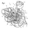
- a turbocharger 1 according to the invention is shown, which has a turbine housing 2 and a compressor housing 3 connected thereto via a bearing housing 28.
- the housings 2, 3 and 28 are arranged along a rotation axis R.
- the turbine housing is shown partially in section to illustrate the arrangement of a vane ring 6 and a radially outer vane 18 formed therefrom which has a plurality of circumferentially spaced vanes 7 with pivot axes 8.
- nozzle cross-sections are formed, which are larger or smaller depending on the position of the guide vanes 7 and apply more or less to the located in the middle of the axis of rotation R turbine rotor 4 with the supplied via a feed channel 9 and discharged via a central port 10 exhaust gas of an engine to drive via the turbine rotor 4 a seated on the same shaft compressor motor 17.
- an actuating device 11 is provided.
- a control housing 12 which controls the control movement of a ram member 14 attached to her to implement the movement thereof to a located behind the blade bearing ring 6 adjusting 5 in a slight rotational movement of the same.
- a clearance 13 for the vanes 7 is formed between the vane ring 6 and an annular part 15 of the turbine housing 2.
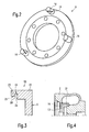
- the blade bearing ring 6 integrally formed spacers 16, which are shown in detail in FIGS. 2 and 3.
- three spacers 16 at an angular distance of 120 ° at the periphery of Blade bearing ring 6 is arranged. In principle, it is possible to provide more or less such spacers 16, but results in the embodiment of FIG. 2 is a particularly advantageous geometric arrangement.
- FIGS. 2 to 4 show an embodiment of the blade bearing ring 6, which has a fastening device 19 for fixing the blade bearing ring 6 on the turbine housing 2, which is arranged in one piece on at least one of the spacers 16.
- the fastening device 19 has a groove 20 which is arranged between a, preferably cylindrically shaped, main part 22 of the spacer 16 and a centering shoulder 23.
- the main part 22 is due to the one-piece design in the blade bearing ring 6 and the centering 23 is arranged at the free end of the spacer 16.
- the centering shoulder 23 is provided with a shoulder relative to the main body 22 so that an axial contact surface 24 and a radially aligned centering surface or a centering diameter result adjacent to the groove 20.
- a web 21 of the turbine housing 2 engages in the groove 20 and thus forms a bayonet-like closure device for fixing the blade bearing ring 6 on the turbine housing 2.
- FIGS. 5 and 6 show an alternative embodiment of the turbocharger 1 according to the invention or the blade bearing ring 6 according to the invention.
- This embodiment has a fastening device 19 ', which instead of a groove on at least one of the spacers 16 and a corresponding web on the turbine housing 2 has a radially aligned centering surface 26 on at least one of the spacers 16, in the assembled state shown in Figs. 5 and 6 interacts with a mating surface 27 of the turbine housing 2. By this interaction, a press fit in the radial direction is achieved, which is sufficient in principle to fix the blade bearing ring 6 on the turbine housing 2.
- a projection 29 is provided which is arranged on an inner circumferential surface 30 of the blade bearing ring 6, which results in detail from FIGS. 5 and 6.
- the projection 29 in this case has radially inward, ie in the direction of the axis of rotation R, and is arranged at the axial end 31 of the blade bearing ring 6, which is the spacers 16 adjacent.
- This projection 29, which forms a radially encircling collar, cooperates with a disk arrangement 32, which is apparent above all from the enlarged representation of FIG. 6.
- the disc assembly 32 has a conical disc spring 33 and a heat shield 34 disposed on the turbine housing 2 side is.
- FIG. 7 is an embodiment of the turbocharger 1, which is intended for a low-temperature use, in which accordingly the material of the turbine housing 2 may have lower temperature resistance.
- a high-temperature resistant insert 35 is provided between the blade bearing ring 6 and the turbine housing 2, which results in detail from the illustration of FIG. 7.
Landscapes
- Engineering & Computer Science (AREA)
- Mechanical Engineering (AREA)
- General Engineering & Computer Science (AREA)
- Supercharger (AREA)
Priority Applications (1)
| Application Number | Priority Date | Filing Date | Title |
|---|---|---|---|
| EP05013040.0A EP1734231B1 (fr) | 2005-06-16 | 2005-06-16 | Turbocompresseur avec turbine a geometrie variable |
Applications Claiming Priority (1)
| Application Number | Priority Date | Filing Date | Title |
|---|---|---|---|
| EP05013040.0A EP1734231B1 (fr) | 2005-06-16 | 2005-06-16 | Turbocompresseur avec turbine a geometrie variable |
Publications (2)
| Publication Number | Publication Date |
|---|---|
| EP1734231A1 true EP1734231A1 (fr) | 2006-12-20 |
| EP1734231B1 EP1734231B1 (fr) | 2018-05-02 |
Family
ID=35229899
Family Applications (1)
| Application Number | Title | Priority Date | Filing Date |
|---|---|---|---|
| EP05013040.0A Expired - Fee Related EP1734231B1 (fr) | 2005-06-16 | 2005-06-16 | Turbocompresseur avec turbine a geometrie variable |
Country Status (1)
| Country | Link |
|---|---|
| EP (1) | EP1734231B1 (fr) |
Cited By (15)
| Publication number | Priority date | Publication date | Assignee | Title |
|---|---|---|---|---|
| WO2008098024A2 (fr) * | 2007-02-08 | 2008-08-14 | Honeywell International Inc. | Procédé de fabrication d'un mécanisme d'aube variable pour un turbocompresseur |
| WO2009076062A2 (fr) | 2007-12-12 | 2009-06-18 | Honeywell International Inc. | Buse variable pour turbocompresseur, comportant une aube distributrice positionnée par des éléments radiaux |
| DE102008020932A1 (de) * | 2008-04-25 | 2009-10-29 | Continental Automotive Gmbh | Turbolader mit einer variablen Turbinengeometrie VTG |
| WO2010040643A1 (fr) * | 2008-10-09 | 2010-04-15 | Continental Automotive Gmbh | Turbocompresseur comprenant des éléments de fixation destinés à la fixation de bagues de palier d'aubes d'une turbine à géométrie variable vtg |
| DE102008014680A1 (de) | 2008-03-18 | 2010-09-23 | Continental Automotive Gmbh | Leitgitteranordnung eines Abgasturboladers, Abgasturbolader und Verfahren zur Herstellung einer Leitgitteranordnung |
| WO2011069571A1 (fr) * | 2009-12-10 | 2011-06-16 | Daimler Ag | Turbine pour un dispositif de suralimentation et procédé pour le montage d'une telle turbine |
| EP2336495A1 (fr) | 2009-12-16 | 2011-06-22 | BorgWarner, Inc. | Turbosoufflante de gaz d'échappement |
| KR20110068847A (ko) | 2009-12-16 | 2011-06-22 | 보르그워너 인코퍼레이티드 | 배기 가스 터보차저 |
| DE102011005151A1 (de) * | 2011-03-04 | 2012-09-06 | Bayerische Motoren Werke Aktiengesellschaft | Abgasturbolader für eine Brennkraftmaschine |
| WO2013072732A1 (fr) * | 2011-11-16 | 2013-05-23 | Toyota Jidosha Kabushiki Kaisha | Turbocompresseur |
| US8662833B2 (en) | 2008-01-21 | 2014-03-04 | Bosch Mahle Turbo Systems Gmbh & Co. Kg | Turbocharger with variable turbine geometry |
| US20150198164A1 (en) * | 2014-01-15 | 2015-07-16 | General Electric Company | Rotary machine having a volute assembly-bearing housing joint with interlocking teeth |
| USD777212S1 (en) | 2015-06-20 | 2017-01-24 | General Electric Company | Nozzle ring |
| WO2020001805A1 (fr) * | 2018-06-27 | 2020-01-02 | Ihi Charging Systems International Gmbh | Turbocompresseur de gaz d'échappement avec couronne directrice centrée |
| DE102008029080B4 (de) | 2008-06-19 | 2022-04-21 | BMTS Technology GmbH & Co. KG | Abgasturbolader für ein Kraftfahrzeug |
Families Citing this family (1)
| Publication number | Priority date | Publication date | Assignee | Title |
|---|---|---|---|---|
| JP7424752B2 (ja) | 2019-03-25 | 2024-01-30 | 株式会社豊田自動織機 | ターボチャージャ |
Citations (4)
| Publication number | Priority date | Publication date | Assignee | Title |
|---|---|---|---|---|
| EP0204033A1 (fr) * | 1985-05-09 | 1986-12-10 | Mtu Motoren- Und Turbinen-Union Friedrichshafen Gmbh | Turbomachine |
| JPH10103070A (ja) * | 1996-09-27 | 1998-04-21 | Toyota Motor Corp | 可変容量ターボチャージャ |
| DE10337491A1 (de) * | 2003-08-14 | 2005-03-17 | Volkswagen Ag | Abgasturbolader für eine Brennkraftmaschine |
| EP1528225A1 (fr) * | 2003-10-27 | 2005-05-04 | BorgWarner Inc. | Turbomachine et méthode de fabrication pour un anneau de guidage |
-
2005
- 2005-06-16 EP EP05013040.0A patent/EP1734231B1/fr not_active Expired - Fee Related
Patent Citations (4)
| Publication number | Priority date | Publication date | Assignee | Title |
|---|---|---|---|---|
| EP0204033A1 (fr) * | 1985-05-09 | 1986-12-10 | Mtu Motoren- Und Turbinen-Union Friedrichshafen Gmbh | Turbomachine |
| JPH10103070A (ja) * | 1996-09-27 | 1998-04-21 | Toyota Motor Corp | 可変容量ターボチャージャ |
| DE10337491A1 (de) * | 2003-08-14 | 2005-03-17 | Volkswagen Ag | Abgasturbolader für eine Brennkraftmaschine |
| EP1528225A1 (fr) * | 2003-10-27 | 2005-05-04 | BorgWarner Inc. | Turbomachine et méthode de fabrication pour un anneau de guidage |
Non-Patent Citations (1)
| Title |
|---|
| PATENT ABSTRACTS OF JAPAN vol. 1998, no. 09 31 July 1998 (1998-07-31) * |
Cited By (30)
| Publication number | Priority date | Publication date | Assignee | Title |
|---|---|---|---|---|
| WO2008098024A3 (fr) * | 2007-02-08 | 2008-10-23 | Honeywell Int Inc | Procédé de fabrication d'un mécanisme d'aube variable pour un turbocompresseur |
| CN101743382B (zh) * | 2007-02-08 | 2013-05-22 | 霍尼韦尔国际公司 | 用于制造涡轮增压器所用的可变叶片机构的方法 |
| WO2008098024A2 (fr) * | 2007-02-08 | 2008-08-14 | Honeywell International Inc. | Procédé de fabrication d'un mécanisme d'aube variable pour un turbocompresseur |
| US7918023B2 (en) | 2007-02-08 | 2011-04-05 | Honeywell International Inc. | Method for manufacturing a variable-vane mechanism for a turbocharger |
| CN101896692B (zh) * | 2007-12-12 | 2014-03-12 | 霍尼韦尔国际公司 | 用于涡轮增压器的具有由径向构件定位的喷嘴环的可变喷嘴 |
| WO2009076062A2 (fr) | 2007-12-12 | 2009-06-18 | Honeywell International Inc. | Buse variable pour turbocompresseur, comportant une aube distributrice positionnée par des éléments radiaux |
| WO2009076062A3 (fr) * | 2007-12-12 | 2010-01-21 | Honeywell International Inc. | Buse variable pour turbocompresseur, comportant une aube distributrice positionnée par des éléments radiaux |
| US8480358B2 (en) | 2007-12-12 | 2013-07-09 | Honeywell International Inc. | Variable nozzle for a turbocharger, having nozzle ring located by radial members |
| CN101896692A (zh) * | 2007-12-12 | 2010-11-24 | 霍尼韦尔国际公司 | 用于涡轮增压器的具有由径向构件定位的喷嘴环的可变喷嘴 |
| US8662833B2 (en) | 2008-01-21 | 2014-03-04 | Bosch Mahle Turbo Systems Gmbh & Co. Kg | Turbocharger with variable turbine geometry |
| DE102008014680A1 (de) | 2008-03-18 | 2010-09-23 | Continental Automotive Gmbh | Leitgitteranordnung eines Abgasturboladers, Abgasturbolader und Verfahren zur Herstellung einer Leitgitteranordnung |
| DE102008020932B4 (de) * | 2008-04-25 | 2010-09-23 | Continental Automotive Gmbh | Turbolader mit einer variablen Turbinengeometrieeinrichtung |
| DE102008020932A1 (de) * | 2008-04-25 | 2009-10-29 | Continental Automotive Gmbh | Turbolader mit einer variablen Turbinengeometrie VTG |
| DE102008029080B4 (de) | 2008-06-19 | 2022-04-21 | BMTS Technology GmbH & Co. KG | Abgasturbolader für ein Kraftfahrzeug |
| CN102177312A (zh) * | 2008-10-09 | 2011-09-07 | 欧陆汽车有限责任公司 | 具有用于固定可变几何形状的涡轮叶片vtg的叶片支撑环的固定部件的涡轮增压器 |
| WO2010040643A1 (fr) * | 2008-10-09 | 2010-04-15 | Continental Automotive Gmbh | Turbocompresseur comprenant des éléments de fixation destinés à la fixation de bagues de palier d'aubes d'une turbine à géométrie variable vtg |
| CN102177312B (zh) * | 2008-10-09 | 2015-04-29 | 大陆汽车有限公司 | 具有用于固定可变几何形状的涡轮叶片vtg的叶片支撑环的固定部件的涡轮增压器 |
| US8764389B2 (en) | 2008-10-09 | 2014-07-01 | Continental Automotive Gmbh | Turbocharger having fastening elements for fastening vane bearing rings of a variable turbine geometry VTG |
| WO2011069571A1 (fr) * | 2009-12-10 | 2011-06-16 | Daimler Ag | Turbine pour un dispositif de suralimentation et procédé pour le montage d'une telle turbine |
| KR20110068847A (ko) | 2009-12-16 | 2011-06-22 | 보르그워너 인코퍼레이티드 | 배기 가스 터보차저 |
| EP2336495A1 (fr) | 2009-12-16 | 2011-06-22 | BorgWarner, Inc. | Turbosoufflante de gaz d'échappement |
| DE102009058411A1 (de) | 2009-12-16 | 2011-06-22 | BorgWarner Inc., Mich. | Abgasturbolader |
| DE102011005151A1 (de) * | 2011-03-04 | 2012-09-06 | Bayerische Motoren Werke Aktiengesellschaft | Abgasturbolader für eine Brennkraftmaschine |
| WO2013072732A1 (fr) * | 2011-11-16 | 2013-05-23 | Toyota Jidosha Kabushiki Kaisha | Turbocompresseur |
| US20150198164A1 (en) * | 2014-01-15 | 2015-07-16 | General Electric Company | Rotary machine having a volute assembly-bearing housing joint with interlocking teeth |
| US9909589B2 (en) * | 2014-01-15 | 2018-03-06 | General Electric Company | Rotary machine having a volute assembly-bearing housing joint with interlocking teeth |
| USD777212S1 (en) | 2015-06-20 | 2017-01-24 | General Electric Company | Nozzle ring |
| WO2020001805A1 (fr) * | 2018-06-27 | 2020-01-02 | Ihi Charging Systems International Gmbh | Turbocompresseur de gaz d'échappement avec couronne directrice centrée |
| CN112292511A (zh) * | 2018-06-27 | 2021-01-29 | Ihi供应系统国际有限责任公司 | 具有定心的导向叶片环的废气涡轮增压器 |
| US11220957B2 (en) | 2018-06-27 | 2022-01-11 | Ihi Charging Systems International Gmbh | Exhaust gas turbocharger |
Also Published As
| Publication number | Publication date |
|---|---|
| EP1734231B1 (fr) | 2018-05-02 |
Similar Documents
| Publication | Publication Date | Title |
|---|---|---|
| EP1734231B1 (fr) | Turbocompresseur avec turbine a geometrie variable | |
| EP2018480B1 (fr) | Turbocompresseur | |
| EP2078136B1 (fr) | Turbocompresseur | |
| EP2209969B1 (fr) | Dispositif de suralimentation | |
| EP1984601B1 (fr) | Turbocompresseur pourvu d'aubes directrices réglables, d'un levier d'aubes et d'une bague de réglage à cet effet | |
| DE112010004597B4 (de) | Turbolader mit variabler Turbinengeometrie | |
| DE102008007670B4 (de) | Steuerring für VTG | |
| EP2167793B1 (fr) | Turbocompresseur a suralimentation de gaz d'échappement pour moteur à combustion interne | |
| DE202005009491U1 (de) | Turbolader | |
| EP2002127A1 (fr) | Dispositif directeur à pré-tourbillonnement | |
| DE112012002746T5 (de) | Abgasturbolader | |
| WO2009092635A2 (fr) | Système de chargement | |
| EP1357255B1 (fr) | Turbocompresseur avec distributeur à géométrie variable | |
| DE112010004596T5 (de) | Turbolade | |
| EP2112332B1 (fr) | Anneau support de distributeur avec canal pressurisé | |
| DE102015113393B4 (de) | Abgasturbolader | |
| EP1998026A2 (fr) | Dispositif de chargement | |
| WO2007107289A1 (fr) | Turbocompresseur dote d'un dispositif de centrage a cartouche | |
| DE102008020732A1 (de) | Ladeeinrichtung | |
| WO2019072464A1 (fr) | Dispositif turbocompresseur comportant un élément à ressort pour serrer le distributeur contre le boîtier de turbine et élément à ressort | |
| DE102008000508A1 (de) | Abgasturbolader mit verstellbarer Turbinengeometrie | |
| DE102004031986B4 (de) | Abgasturbolader für eine Brennkraftmaschine | |
| DE102007052735B4 (de) | Ladeeinrichtung | |
| EP2805027A1 (fr) | Turbocompresseur à gaz d'échappement | |
| DE102004023211A1 (de) | Abgasturbolader für eine Brennkraftmaschine mit variabler Turbinengeometrie |
Legal Events
| Date | Code | Title | Description |
|---|---|---|---|
| PUAI | Public reference made under article 153(3) epc to a published international application that has entered the european phase |
Free format text: ORIGINAL CODE: 0009012 |
|
| 17P | Request for examination filed |
Effective date: 20050616 |
|
| AK | Designated contracting states |
Kind code of ref document: A1 Designated state(s): AT BE BG CH CY CZ DE DK EE ES FI FR GB GR HU IE IS IT LI LT LU MC NL PL PT RO SE SI SK TR |
|
| AX | Request for extension of the european patent |
Extension state: AL BA HR LV MK YU |
|
| AKX | Designation fees paid |
Designated state(s): DE FR GB IT NL |
|
| 17Q | First examination report despatched |
Effective date: 20150323 |
|
| GRAP | Despatch of communication of intention to grant a patent |
Free format text: ORIGINAL CODE: EPIDOSNIGR1 |
|
| STAA | Information on the status of an ep patent application or granted ep patent |
Free format text: STATUS: GRANT OF PATENT IS INTENDED |
|
| INTG | Intention to grant announced |
Effective date: 20171214 |
|
| GRAS | Grant fee paid |
Free format text: ORIGINAL CODE: EPIDOSNIGR3 |
|
| GRAA | (expected) grant |
Free format text: ORIGINAL CODE: 0009210 |
|
| STAA | Information on the status of an ep patent application or granted ep patent |
Free format text: STATUS: THE PATENT HAS BEEN GRANTED |
|
| AK | Designated contracting states |
Kind code of ref document: B1 Designated state(s): DE FR GB IT NL |
|
| REG | Reference to a national code |
Ref country code: GB Ref legal event code: FG4D Free format text: NOT ENGLISH |
|
| REG | Reference to a national code |
Ref country code: DE Ref legal event code: R096 Ref document number: 502005015824 Country of ref document: DE |
|
| REG | Reference to a national code |
Ref country code: NL Ref legal event code: MP Effective date: 20180502 |
|
| PG25 | Lapsed in a contracting state [announced via postgrant information from national office to epo] |
Ref country code: NL Free format text: LAPSE BECAUSE OF FAILURE TO SUBMIT A TRANSLATION OF THE DESCRIPTION OR TO PAY THE FEE WITHIN THE PRESCRIBED TIME-LIMIT Effective date: 20180502 |
|
| REG | Reference to a national code |
Ref country code: DE Ref legal event code: R097 Ref document number: 502005015824 Country of ref document: DE |
|
| PG25 | Lapsed in a contracting state [announced via postgrant information from national office to epo] |
Ref country code: IT Free format text: LAPSE BECAUSE OF FAILURE TO SUBMIT A TRANSLATION OF THE DESCRIPTION OR TO PAY THE FEE WITHIN THE PRESCRIBED TIME-LIMIT Effective date: 20180502 |
|
| PLBE | No opposition filed within time limit |
Free format text: ORIGINAL CODE: 0009261 |
|
| STAA | Information on the status of an ep patent application or granted ep patent |
Free format text: STATUS: NO OPPOSITION FILED WITHIN TIME LIMIT |
|
| 26N | No opposition filed |
Effective date: 20190205 |
|
| GBPC | Gb: european patent ceased through non-payment of renewal fee |
Effective date: 20180802 |
|
| PG25 | Lapsed in a contracting state [announced via postgrant information from national office to epo] |
Ref country code: FR Free format text: LAPSE BECAUSE OF NON-PAYMENT OF DUE FEES Effective date: 20180702 |
|
| PGFP | Annual fee paid to national office [announced via postgrant information from national office to epo] |
Ref country code: DE Payment date: 20190515 Year of fee payment: 15 |
|
| PG25 | Lapsed in a contracting state [announced via postgrant information from national office to epo] |
Ref country code: GB Free format text: LAPSE BECAUSE OF NON-PAYMENT OF DUE FEES Effective date: 20180802 |
|
| REG | Reference to a national code |
Ref country code: DE Ref legal event code: R119 Ref document number: 502005015824 Country of ref document: DE |
|
| PG25 | Lapsed in a contracting state [announced via postgrant information from national office to epo] |
Ref country code: DE Free format text: LAPSE BECAUSE OF NON-PAYMENT OF DUE FEES Effective date: 20210101 |