EP1734231A1 - Turbocharger and nozzle mounting ring therefor - Google Patents
Turbocharger and nozzle mounting ring therefor Download PDFInfo
- Publication number
- EP1734231A1 EP1734231A1 EP20050013040 EP05013040A EP1734231A1 EP 1734231 A1 EP1734231 A1 EP 1734231A1 EP 20050013040 EP20050013040 EP 20050013040 EP 05013040 A EP05013040 A EP 05013040A EP 1734231 A1 EP1734231 A1 EP 1734231A1
- Authority
- EP
- European Patent Office
- Prior art keywords
- bearing ring
- blade bearing
- turbine housing
- turbocharger
- turbocharger according
- Prior art date
- Legal status (The legal status is an assumption and is not a legal conclusion. Google has not performed a legal analysis and makes no representation as to the accuracy of the status listed.)
- Granted
Links
Images


Classifications
-
- F—MECHANICAL ENGINEERING; LIGHTING; HEATING; WEAPONS; BLASTING
- F01—MACHINES OR ENGINES IN GENERAL; ENGINE PLANTS IN GENERAL; STEAM ENGINES
- F01D—NON-POSITIVE DISPLACEMENT MACHINES OR ENGINES, e.g. STEAM TURBINES
- F01D17/00—Regulating or controlling by varying flow
- F01D17/10—Final actuators
- F01D17/12—Final actuators arranged in stator parts
- F01D17/14—Final actuators arranged in stator parts varying effective cross-sectional area of nozzles or guide conduits
- F01D17/16—Final actuators arranged in stator parts varying effective cross-sectional area of nozzles or guide conduits by means of nozzle vanes
- F01D17/165—Final actuators arranged in stator parts varying effective cross-sectional area of nozzles or guide conduits by means of nozzle vanes for radial flow, i.e. the vanes turning around axes which are essentially parallel to the rotor centre line
-
- F—MECHANICAL ENGINEERING; LIGHTING; HEATING; WEAPONS; BLASTING
- F01—MACHINES OR ENGINES IN GENERAL; ENGINE PLANTS IN GENERAL; STEAM ENGINES
- F01D—NON-POSITIVE DISPLACEMENT MACHINES OR ENGINES, e.g. STEAM TURBINES
- F01D25/00—Component parts, details, or accessories, not provided for in, or of interest apart from, other groups
- F01D25/24—Casings; Casing parts, e.g. diaphragms, casing fastenings
- F01D25/246—Fastening of diaphragms or stator-rings
-
- F—MECHANICAL ENGINEERING; LIGHTING; HEATING; WEAPONS; BLASTING
- F05—INDEXING SCHEMES RELATING TO ENGINES OR PUMPS IN VARIOUS SUBCLASSES OF CLASSES F01-F04
- F05D—INDEXING SCHEME FOR ASPECTS RELATING TO NON-POSITIVE-DISPLACEMENT MACHINES OR ENGINES, GAS-TURBINES OR JET-PROPULSION PLANTS
- F05D2220/00—Application
- F05D2220/40—Application in turbochargers
-
- F—MECHANICAL ENGINEERING; LIGHTING; HEATING; WEAPONS; BLASTING
- F05—INDEXING SCHEMES RELATING TO ENGINES OR PUMPS IN VARIOUS SUBCLASSES OF CLASSES F01-F04
- F05D—INDEXING SCHEME FOR ASPECTS RELATING TO NON-POSITIVE-DISPLACEMENT MACHINES OR ENGINES, GAS-TURBINES OR JET-PROPULSION PLANTS
- F05D2230/00—Manufacture
- F05D2230/60—Assembly methods
- F05D2230/64—Assembly methods using positioning or alignment devices for aligning or centring, e.g. pins
-
- F—MECHANICAL ENGINEERING; LIGHTING; HEATING; WEAPONS; BLASTING
- F05—INDEXING SCHEMES RELATING TO ENGINES OR PUMPS IN VARIOUS SUBCLASSES OF CLASSES F01-F04
- F05D—INDEXING SCHEME FOR ASPECTS RELATING TO NON-POSITIVE-DISPLACEMENT MACHINES OR ENGINES, GAS-TURBINES OR JET-PROPULSION PLANTS
- F05D2260/00—Function
- F05D2260/30—Retaining components in desired mutual position
- F05D2260/33—Retaining components in desired mutual position with a bayonet coupling
Definitions
- the invention relates to a turbocharger according to the preamble of claim 1 and a blade bearing ring therefor according to the preamble of claim 11.
- Such a turbocharger or such a blade bearing ring is from the EP 1 394 364 A1 known.
- the vane ring is provided with spacers to maintain a clearance for the vanes of a baffle.
- the spacers of the blade bearing ring are each provided with a bore for connecting bolts. In the assembled state, the connecting bolts pass through the holes and engage in a bearing ring of the turbine housing arranged adjacent to the blade bearing ring.
- a kind of bayonet lock is possible, which is formed by a groove which is arranged on at least one of the spacers of the blade bearing ring and cooperates in the assembled state with a suitably designed and arranged web of the turbine housing.
- An alternative preferred embodiment provides as a fastening means a radially aligned centering surface, which forms a press fit with a suitably arranged and formed counter surface of the turbine housing in the assembled state.
- Radial alignment in this context means that the centering surface has radially inwardly with respect to the axis of rotation of the turbine rotor, wherein the mating surface of the turbine housing accordingly faces radially outward.
- the fastener in forming the fastener as a press fit, it is also possible to provide additional axial securing of the vane ring by cooperating with a disc assembly disposed between the turbine housing and the bearing housing of the turbocharger.
- This disc assembly can be formed in a particularly preferred embodiment by a arranged on the side of the bearing housing disc spring and a heat shield, the facing the turbine housing.
- the turbine housing is formed of a material which has a low temperature resistance
- an insert disk of particularly temperature-resistant material for protecting the guide vanes between the blade bearing ring and the turbine housing.
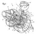
- a turbocharger 1 according to the invention is shown, which has a turbine housing 2 and a compressor housing 3 connected thereto via a bearing housing 28.
- the housings 2, 3 and 28 are arranged along a rotation axis R.
- the turbine housing is shown partially in section to illustrate the arrangement of a vane ring 6 and a radially outer vane 18 formed therefrom which has a plurality of circumferentially spaced vanes 7 with pivot axes 8.
- nozzle cross-sections are formed, which are larger or smaller depending on the position of the guide vanes 7 and apply more or less to the located in the middle of the axis of rotation R turbine rotor 4 with the supplied via a feed channel 9 and discharged via a central port 10 exhaust gas of an engine to drive via the turbine rotor 4 a seated on the same shaft compressor motor 17.
- an actuating device 11 is provided.
- a control housing 12 which controls the control movement of a ram member 14 attached to her to implement the movement thereof to a located behind the blade bearing ring 6 adjusting 5 in a slight rotational movement of the same.
- a clearance 13 for the vanes 7 is formed between the vane ring 6 and an annular part 15 of the turbine housing 2.
- the blade bearing ring 6 integrally formed spacers 16, which are shown in detail in FIGS. 2 and 3.
- three spacers 16 at an angular distance of 120 ° at the periphery of Blade bearing ring 6 is arranged. In principle, it is possible to provide more or less such spacers 16, but results in the embodiment of FIG. 2 is a particularly advantageous geometric arrangement.
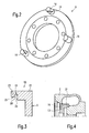
- FIGS. 2 to 4 show an embodiment of the blade bearing ring 6, which has a fastening device 19 for fixing the blade bearing ring 6 on the turbine housing 2, which is arranged in one piece on at least one of the spacers 16.
- the fastening device 19 has a groove 20 which is arranged between a, preferably cylindrically shaped, main part 22 of the spacer 16 and a centering shoulder 23.
- the main part 22 is due to the one-piece design in the blade bearing ring 6 and the centering 23 is arranged at the free end of the spacer 16.
- the centering shoulder 23 is provided with a shoulder relative to the main body 22 so that an axial contact surface 24 and a radially aligned centering surface or a centering diameter result adjacent to the groove 20.
- a web 21 of the turbine housing 2 engages in the groove 20 and thus forms a bayonet-like closure device for fixing the blade bearing ring 6 on the turbine housing 2.
- FIGS. 5 and 6 show an alternative embodiment of the turbocharger 1 according to the invention or the blade bearing ring 6 according to the invention.
- This embodiment has a fastening device 19 ', which instead of a groove on at least one of the spacers 16 and a corresponding web on the turbine housing 2 has a radially aligned centering surface 26 on at least one of the spacers 16, in the assembled state shown in Figs. 5 and 6 interacts with a mating surface 27 of the turbine housing 2. By this interaction, a press fit in the radial direction is achieved, which is sufficient in principle to fix the blade bearing ring 6 on the turbine housing 2.
- a projection 29 is provided which is arranged on an inner circumferential surface 30 of the blade bearing ring 6, which results in detail from FIGS. 5 and 6.
- the projection 29 in this case has radially inward, ie in the direction of the axis of rotation R, and is arranged at the axial end 31 of the blade bearing ring 6, which is the spacers 16 adjacent.
- This projection 29, which forms a radially encircling collar, cooperates with a disk arrangement 32, which is apparent above all from the enlarged representation of FIG. 6.
- the disc assembly 32 has a conical disc spring 33 and a heat shield 34 disposed on the turbine housing 2 side is.
- FIG. 7 is an embodiment of the turbocharger 1, which is intended for a low-temperature use, in which accordingly the material of the turbine housing 2 may have lower temperature resistance.
- a high-temperature resistant insert 35 is provided between the blade bearing ring 6 and the turbine housing 2, which results in detail from the illustration of FIG. 7.
Abstract
Description
Die Erfindung betrifft einen Turbolader gemäß dem Oberbegriff des Anspruches 1 sowie einen Schaufellagerring hierfür gemäß dem Oberbegriff des Anspruches 11.The invention relates to a turbocharger according to the preamble of
Ein derartiger Turbolader bzw. ein derartiger Schaufellagerring ist aus der
Bei dieser Turboladerkonstruktion wird der Schaufellagerring mit Abstandshaltern zur Aufrechterhaltung eines Freiraumes für die Leitschaufeln eines Leitgitters versehen. Um den Schaufellagerring am Turbinengehäuse fixieren zu können, sind die Abstandshalter des Schaufellagerrings jeweils mit einer Bohrung für Verbindungsbolzen versehen. Im Montagezustand durchsetzen die Verbindungsbolzen die Bohrungen und greifen in einen benachbart zum Schaufellagerring angeordneten Lagerring des Turbinengehäuses ein.In this turbocharger design, the vane ring is provided with spacers to maintain a clearance for the vanes of a baffle. In order to fix the blade bearing ring on the turbine housing, the spacers of the blade bearing ring are each provided with a bore for connecting bolts. In the assembled state, the connecting bolts pass through the holes and engage in a bearing ring of the turbine housing arranged adjacent to the blade bearing ring.
Es ist demgegenüber Aufgabe der vorliegenden Erfindung, einen Turbolader gemäß dem Oberbegriff des Anspruches 1 bzw. einen Schaufellagerring gemäß dem Oberbegriff des Anspruches 11 zu schaffen, die eine Vereinfachung der Montage durch Reduzierung der zu montierenden Einzelteile ermöglichen.It is accordingly an object of the present invention to provide a turbocharger according to the preamble of
Die Lösung dieser Aufgabe erfolgt durch die Merkmale des Anspruches 1 bzw. des Anspruches 11.The solution of this problem is achieved by the features of
Durch die erfindungsgemäße einstückige Ausbildung der Befestigungseinrichtung zur Fixierung des Schaufellagerrings an den Abstandshaltern desselben ist es möglich, sowohl auf die Anbringung von Bohrungen in den Abstandshaltern als auch das Vorsehen und Montieren von separaten Verbindungsbolzen zu verzichten.As a result of the one-piece design of the fastening device according to the invention for fixing the blade bearing ring to the spacers, it is possible to dispense with the attachment of bores in the spacers as well as the provision and mounting of separate connecting bolts.
Vielmehr kann im Zuge der Anordnung des Schaufellagerrings dessen Fixierung durch Ineingriffbringen von Passflächen der Befestigungseinrichtung des Schaufellagerringes und entsprechender Gegenflächen am Turbinengehäuse erreicht werden.Rather, in the course of the arrangement of the blade bearing ring whose fixation can be achieved by engaging mating surfaces of the fastening device of the blade bearing ring and corresponding mating surfaces on the turbine housing.
Die Unteransprüche haben vorteilhafte Weiterbildungen der Erfindung zum Inhalt.The dependent claims have advantageous developments of the invention to the content.
Als eine Alternative für die erfindungsgemäße Befestigungseinrichtung ist eine Art Bajonettverschluss möglich, der durch eine Nut gebildet wird, die an zumindest einem der Abstandshalter des Schaufellagerrings angeordnet ist und im Montagezustand mit einem passend ausgebildeten und angeordneten Steg des Turbinengehäuses zusammenwirkt.As an alternative to the fastening device according to the invention a kind of bayonet lock is possible, which is formed by a groove which is arranged on at least one of the spacers of the blade bearing ring and cooperates in the assembled state with a suitably designed and arranged web of the turbine housing.
Eine alternative bevorzugte Ausführungsform sieht als Befestigungseinrichtung eine radial ausgerichtete Zentrierfläche vor, die im Montagezustand eine Presspassung mit einer geeignet angeordneten und ausgebildeten Gegenfläche des Turbinengehäuses bildet. Radiale Ausrichtung bedeutet in diesem Zusammenhang, dass die Zentrierfläche radial nach innen bezogen auf die Rotationsachse des Turbinenrotors weist, wobei die Gegenfläche des Turbinengehäuses dementsprechend radial nach außen weist.An alternative preferred embodiment provides as a fastening means a radially aligned centering surface, which forms a press fit with a suitably arranged and formed counter surface of the turbine housing in the assembled state. Radial alignment in this context means that the centering surface has radially inwardly with respect to the axis of rotation of the turbine rotor, wherein the mating surface of the turbine housing accordingly faces radially outward.
Bei der Ausbildung der Befestigungseinrichtung als Presspassung ist es ferner möglich, eine zusätzliche axiale Sicherung des Schaufellagerrings durch ein Zusammenwirken mit einer Scheibenanordnung zu bewirken, die zwischen dem Turbinengehäuse und dem Lagergehäuse des Turboladers angeordnet ist. Diese Scheibenanordnung kann bei einer besonders bevorzugten Ausführungsform durch eine auf der Seite des Lagergehäuses angeordnete Tellerfeder und einem Hitzeschild gebildet werden, der dem Turbinengehäuse zugewandt ist.In forming the fastener as a press fit, it is also possible to provide additional axial securing of the vane ring by cooperating with a disc assembly disposed between the turbine housing and the bearing housing of the turbocharger. This disc assembly can be formed in a particularly preferred embodiment by a arranged on the side of the bearing housing disc spring and a heat shield, the facing the turbine housing.
Für Anwendungen im Niedertemperaturbereich, bei dem das Turbinengehäuse aus einem Werkstoff ausgebildet ist, der eine geringe Temperaturbeständigkeit hat, ist es möglich, zwischen dem Schaufellagerring und dem Turbinengehäuse eine Einlegescheibe aus besonders temperaturfestem Material zum Schutz der Leitschaufeln anzuordnen.For applications in the low temperature range, in which the turbine housing is formed of a material which has a low temperature resistance, it is possible to arrange an insert disk of particularly temperature-resistant material for protecting the guide vanes between the blade bearing ring and the turbine housing.
Weitere Einzelheiten, Merkmale und Vorteile der Erfindung ergeben sich aus nachfolgender Beschreibung von Ausführungsbeispielen anhand der Zeichnungen.Further details, features and advantages of the invention will become apparent from the following description of exemplary embodiments with reference to the drawings.
Es zeigt:
- Fig. 1
- eine teilweise im Schnitt dargestellte Perspektivansicht eines erfindungsgemäßen Turboladers,
- Fig. 2
- eine perspektivische Ansicht eines erfindungsgemäßen Schaufellagerrings,
- Fig. 3
- eine Teilansicht des Schaufellagerrings gemäß Fig. 2,
- Fig. 4
- eine Teilansicht des erfindungsgemäßen Turboladers zur Verdeutlichung des Montagezustandes des Schaufellagerrings gemäß der Fig. 2 und 3,
- Fig. 5 und 6
- der Fig. 4 entsprechende Darstellungen des erfindungsgemäßen Turboladers zur Verdeutlichung einer alternativen Ausführungsform des erfindungsgemäßen Schaufellagerrings, und
- Fig. 7
- eine der Fig. 5 entsprechende Darstellung eines Teiles des erfindungsgemäßen Turboladers zur Verdeutlichung einer weiteren Ausführungsform.
- Fig. 1
- a partially sectioned perspective view of a turbocharger according to the invention,
- Fig. 2
- a perspective view of a blade bearing ring according to the invention,
- Fig. 3
- 2 is a partial view of the blade bearing ring according to FIG. 2,
- Fig. 4
- 2 shows a partial view of the turbocharger according to the invention for clarifying the mounting state of the blade bearing ring according to FIGS. 2 and 3,
- FIGS. 5 and 6
- 4 corresponding representations of the turbocharger according to the invention to illustrate an alternative embodiment of the blade bearing ring according to the invention, and
- Fig. 7
- one of Fig. 5 corresponding representation of a Part of the turbocharger according to the invention to illustrate a further embodiment.
In Fig. 1 ist ein erfindungsgemäßer Turbolader 1 dargestellt, der ein Turbinengehäuse 2 und ein damit über ein Lagergehäuse 28 verbundenes Kompressorgehäuse 3 aufweist. Die Gehäuse 2, 3 und 28 sind entlang einer Rotationsachse R angeordnet. Das Turbinengehäuse ist teilweise im Schnitt gezeigt, um die Anordnung eines Schaufellagerrings 6 und ein von diesem gebildetes radial äußeres Leitgitter 18 zu verdeutlichen, das eine Mehrzahl von über den Umfang verteilten Leitschaufeln 7 mit Schwenkachsen 8 aufweist. Hierdurch werden Düsenquerschnitte gebildet, die je nach der Lage der Leitschaufeln 7 größer oder kleiner sind und den in der Mitte an der Rotationsachse R gelegenen Turbinenrotor 4 mehr oder weniger mit dem über einen Zuführkanal 9 zugeführten und über einen Zentralstutzen 10 abgeführten Abgas eines Motors beaufschlagen, um über den Turbinenrotor 4 einen auf derselben Welle sitzenden Kompressorrotor 17 anzutreiben.In Fig. 1, a
Um die Bewegung bzw. die Lage der Leitschaufeln 7 zu steuern, ist eine Betätigungseinrichtung 11 vorgesehen. Diese kann an sich beliebig ausgebildet sein, jedoch weist eine bevorzugte Ausführungsform ein Steuergehäuse 12 auf, das die Steuerbewegung eines an ihr befestigten Stößelgliedes 14 steuert, um dessen Bewegung auf einen hinter dem Schaufellagerring 6 gelegenen Verstellring 5 in eine leichte Drehbewegung desselben umzusetzen. Zwischen dem Schaufellagerring 6 und einem ringförmigen Teil 15 des Turbinengehäuses 2 wird ein Freiraum 13 für die Leitschaufeln 7 gebildet. Um diesen Freiraum 13 sichern zu können, weist der Schaufellagerring 6 einstückig angeformte Abstandshalter 16 auf, die im Detail in Fig. 2 und 3 dargestellt sind. Im Beispielsfalle sind drei Abstandshalter 16 in einem Winkelabstand von jeweils 120° am Umfang des Schaufellagerrings 6 angeordnet. Vom Prinzip her ist es möglich, mehr oder weniger derartige Abstandshalter 16 vorzusehen, jedoch ergibt die Ausbildung gemäß Fig. 2 eine besonders vorteilhafte geometrische Anordnung.In order to control the movement or the position of the
In den Fig. 2 bis 4 ist eine Ausführungsform des Schaufellagerrings 6 dargestellt, der eine Befestigungseinrichtung 19 zur Fixierung des Schaufellagerrings 6 am Turbinengehäuse 2 aufweist, die einstückig an zumindestens einem der Abstandshalter 16 angeordnet ist. Bei der in diesen Figuren dargestellten Ausführungsform weist die Befestigungseinrichtung 19 eine Nut 20 auf, die zwischen einem, vorzugsweise zylindrisch ausgebildeten, Hauptteil 22 des Abstandshalters 16 und einem Zentrierabsatz 23 angeordnet ist. Wie sich aus der Detailansicht der Fig. 3 ergibt, geht der Hauptteil 22 aufgrund der einstückigen Ausbildung in den Schaufellagerring 6 über und der Zentrierabsatz 23 ist am freien Ende des Abstandshalters 16 angeordnet. Durch das Anbringen der Nut 20 zwischen dem Hauptteil 22 und dem Zentrierabsatz 23 ergibt sich die aus Fig. 3 im Einzelnen ersichtliche Hakenform. Wie Fig. 3 ferner verdeutlicht, ist der Zentrierabsatz 23 gegenüber dem Hauptkörper 22 mit einem Absatz versehen, so dass sich benachbart zur Nut 20 eine axiale Anlagefläche 24 sowie eine radial ausgerichtete Zentrierfläche bzw. ein Zentrierdurchmesser ergeben.FIGS. 2 to 4 show an embodiment of the blade bearing
Im in Fig. 4 dargestellten Montagezustand greift ein Steg 21 des Turbinengehäuses 2 in die Nut 20 ein und bildet damit eine bajonettähnliche Verschlusseinrichtung zur Fixierung des Schaufellagerrings 6 am Turbinengehäuse 2.In the assembled state shown in FIG. 4, a
Hierzu und zur Ausbildung des Schaufellagerrings gemäß der Ausführungsformen der Fig. 2 bis 4 wird neben der schriftlichen Beschreibung explizit auf die zeichnerische Darstellung der genannten Figuren verwiesen.For this purpose and for the design of the blade bearing ring according to the embodiments of Figs. 2 to 4 is in addition to the written description explicitly to the graphic representation referenced figures.
In den Fig. 5 und 6 ist eine alternative Ausbildung des erfindungsgemäßen Turboladers 1 bzw. des erfindungsgemäßen Schaufellagerrings 6 dargestellt.FIGS. 5 and 6 show an alternative embodiment of the
Diese Ausführungsform weist eine Befestigungseinrichtung 19' auf, die anstatt einer Nut an zumindestens einem der Abstandshalter 16 und einem korrespondierenden Steg am Turbinengehäuse 2 eine radial ausgerichtete Zentrierfläche 26 an zumindestens einem der Abstandshalter 16 aufweist, die im in den Fig. 5 und 6 dargestellten Montagezustand mit einer Gegenfläche 27 des Turbinengehäuses 2 zusammenwirkt. Durch dieses Zusammenwirken wird eine Presspassung in radialer Richtung erreicht, die vom Prinzip her dazu ausreicht, den Schaufellagerring 6 am Turbinengehäuse 2 zu fixieren.This embodiment has a fastening device 19 ', which instead of a groove on at least one of the
Um die Fixierung zu unterstützen ist bei den in den Fig. 5 und 6 besonders bevorzugten Ausführungsform ferner ein Vorsprung 29 vorgesehen, der an einer Innenumfangsfläche 30 des Schaufellagerrings 6 angeordnet ist, was sich im Einzelnen aus den Fig. 5 und 6 ergibt.In order to assist the fixation, in the embodiment particularly preferred in FIGS. 5 and 6, a
Der Vorsprung 29 weist hierbei radial nach innen, also in Richtung auf die Rotationsachse R, und ist an dem axialen Ende 31 des Schaufellagerrings 6 angeordnet, das den Abstandshaltern 16 benachbart ist. Dieser Vorsprung 29, der einen radial umlaufenden Bund bildet, wirkt mit einer Scheibenanordnung 32 zusammen, was vor allem aus der vergrößerten Darstellung der Fig. 6 ersichtlich ist.The
Bei der dargestellten Ausführungsform weist die Scheibenanordnung 32 eine konisch ausgebildete Tellerfeder 33 und einen Hitzeschild 34 auf, der auf Seiten des Turbinengehäuses 2 angeordnet ist.In the illustrated embodiment, the
Dadurch, dass die Scheibenanordnung 32 an ihrem radial äußeren Ende auf dem Vorsprung 29 aufliegt, ist es möglich, bei der Montage eine axiale Kraft F (siehe Fig. 5) aufzubringen, die eine zusätzliche axiale Verspannung des Schaufellagerrings 6 möglich macht. In Fig. 7 ist eine Anordnung dargestellt, die derjenigen der Fig. 5 und 6 weitestgehend entspricht, so dass auf die voranstehende Erläuterung Bezug genommen werden kann.Due to the fact that the
Es handelt sich bei der Fig. 7 jedoch um eine Ausführungsform des Turboladers 1, die für einen Niedertemperatureinsatz vorgesehen ist, bei der dementsprechend das Material des Turbinengehäuses 2 geringere Temperaturfestigkeit haben kann.However, FIG. 7 is an embodiment of the
Um jedoch die Leitschaufeln 7 schützen zu können, ist eine hochtemperaturfeste Einlegescheibe 35 zwischen dem Schaufellagerring 6 und dem Turbinengehäuse 2 vorgesehen, was sich im Einzelnen aus der Darstellung der Fig. 7 ergibt.However, in order to protect the
- 11
- Turboladerturbocharger
- 22
- TubinengehäuseTubinengehäuse
- 33
- Kompressorgehäusecompressor housing
- 44
- Turbinenrotorturbine rotor
- 55
- Verstellringadjusting
- 66
- SchaufellagerringNozzle ring
- 77
- Leitschaufelnvanes
- 88th
- Schwenkachsenswiveling axes
- 99
- Zuführkanalfeed
- 1010
- AxialstutzenAxialstutzen
- 1111
- Betätigungseinrichtungactuator
- 1212
- Steuergehäusecontrol housing
- 1313
-
Freiraum für Leitschaufeln 7Free space for
vanes 7 - 1414
- Stößelgliedplunger member
- 1515
-
ringförmiger Teil des Turbinengehäuses 2annular part of the
turbine housing 2 - 1616
- Abstandshalter/DistanznockenSpacer / spacer cams
- 1717
- Kompressorrotorcompressor rotor
- 1818
- Leitgitterguide grid
- 1919
- Befestigungseinrichtungfastening device
- 2020
- Nutgroove
- 2121
- Stegweb
- 2222
- HauptteilBulk
- 2323
- Zentrierabsatzcentering
- 2424
- axiale Anlageflächeaxial contact surface
- 2525
- Zentrierfläche bzw. Zentrierdurchmesser des AbstandshaltersCentering or centering diameter of the spacer
- 2626
- Zentrierflächecentering
- 2727
- Gegenflächecounter surface
- 2828
- Lagergehäusebearing housing
- 2929
- Vorsprunghead Start
- 3030
- InnenumfangsflächeInner circumferential surface
- 3131
- axiales Endeaxial end
- 3232
- Scheibenanordnungdisk assembly
- 3333
- TellerfederBelleville spring
- 3434
- Hitzeschildheat shield
- 3535
- Einlegescheibeinsert disc
- RR
- Rotationsachseaxis of rotation
- FF
- axiale Vorspannkraftaxial preload force
Claims (11)
Priority Applications (1)
| Application Number | Priority Date | Filing Date | Title |
|---|---|---|---|
| EP05013040.0A EP1734231B1 (en) | 2005-06-16 | 2005-06-16 | Turbocharger with variable geometry turbine |
Applications Claiming Priority (1)
| Application Number | Priority Date | Filing Date | Title |
|---|---|---|---|
| EP05013040.0A EP1734231B1 (en) | 2005-06-16 | 2005-06-16 | Turbocharger with variable geometry turbine |
Publications (2)
| Publication Number | Publication Date |
|---|---|
| EP1734231A1 true EP1734231A1 (en) | 2006-12-20 |
| EP1734231B1 EP1734231B1 (en) | 2018-05-02 |
Family
ID=35229899
Family Applications (1)
| Application Number | Title | Priority Date | Filing Date |
|---|---|---|---|
| EP05013040.0A Expired - Fee Related EP1734231B1 (en) | 2005-06-16 | 2005-06-16 | Turbocharger with variable geometry turbine |
Country Status (1)
| Country | Link |
|---|---|
| EP (1) | EP1734231B1 (en) |
Cited By (15)
| Publication number | Priority date | Publication date | Assignee | Title |
|---|---|---|---|---|
| WO2008098024A2 (en) * | 2007-02-08 | 2008-08-14 | Honeywell International Inc. | Method for manufacturing a variable-vane mechanism for a turbocharger |
| WO2009076062A2 (en) | 2007-12-12 | 2009-06-18 | Honeywell International Inc. | Variable nozzle for a turbocharger, having nozzle ring located by radial members |
| DE102008020932A1 (en) * | 2008-04-25 | 2009-10-29 | Continental Automotive Gmbh | Turbocharger, particularly for motor vehicle, has variable turbine geometry unit and one or multiple fastening elements for fastening variable turbine geometry unit in housing of turbocharger |
| WO2010040643A1 (en) * | 2008-10-09 | 2010-04-15 | Continental Automotive Gmbh | Turbocharger having fastening elements for fastening blade bearing rings of a variable turbine geometry vtg |
| DE102008014680A1 (en) | 2008-03-18 | 2010-09-23 | Continental Automotive Gmbh | Leitgitteranordnung an exhaust gas turbocharger, exhaust gas turbocharger and method for producing a Leitgitteranordnung |
| WO2011069571A1 (en) * | 2009-12-10 | 2011-06-16 | Daimler Ag | Turbine for a supercharger device, and method for mounting a turbine of this type |
| KR20110068847A (en) | 2009-12-16 | 2011-06-22 | 보르그워너 인코퍼레이티드 | Exhaust-gas turbocharger |
| EP2336495A1 (en) | 2009-12-16 | 2011-06-22 | BorgWarner, Inc. | Exhaust gas turbo charger |
| DE102011005151A1 (en) * | 2011-03-04 | 2012-09-06 | Bayerische Motoren Werke Aktiengesellschaft | Exhaust turbocharger for internal combustion engine, has water turbine distributor for variable turbine geometry, where water turbine distributor has two swiveling guide vanes between two parallel, annular slide walls |
| WO2013072732A1 (en) * | 2011-11-16 | 2013-05-23 | Toyota Jidosha Kabushiki Kaisha | Turbocharger |
| US8662833B2 (en) | 2008-01-21 | 2014-03-04 | Bosch Mahle Turbo Systems Gmbh & Co. Kg | Turbocharger with variable turbine geometry |
| US20150198164A1 (en) * | 2014-01-15 | 2015-07-16 | General Electric Company | Rotary machine having a volute assembly-bearing housing joint with interlocking teeth |
| USD777212S1 (en) | 2015-06-20 | 2017-01-24 | General Electric Company | Nozzle ring |
| WO2020001805A1 (en) * | 2018-06-27 | 2020-01-02 | Ihi Charging Systems International Gmbh | Turbocharger with centered guide blade ring |
| DE102008029080B4 (en) | 2008-06-19 | 2022-04-21 | BMTS Technology GmbH & Co. KG | Exhaust gas turbocharger for a motor vehicle |
Families Citing this family (1)
| Publication number | Priority date | Publication date | Assignee | Title |
|---|---|---|---|---|
| JP7424752B2 (en) | 2019-03-25 | 2024-01-30 | 株式会社豊田自動織機 | turbo charger |
Citations (4)
| Publication number | Priority date | Publication date | Assignee | Title |
|---|---|---|---|---|
| EP0204033A1 (en) * | 1985-05-09 | 1986-12-10 | Mtu Motoren- Und Turbinen-Union Friedrichshafen Gmbh | Turbo machine |
| JPH10103070A (en) * | 1996-09-27 | 1998-04-21 | Toyota Motor Corp | Variable displacement turbocharger |
| DE10337491A1 (en) * | 2003-08-14 | 2005-03-17 | Volkswagen Ag | Exhaust gas turbocharger for IC engines esp. for motor vehicles has flow channel component fastened by bolts, with one bolt passing through turbine guide blade to form pivot axis |
| EP1528225A1 (en) * | 2003-10-27 | 2005-05-04 | BorgWarner Inc. | Turbomachine and production method for a stator assembly |
-
2005
- 2005-06-16 EP EP05013040.0A patent/EP1734231B1/en not_active Expired - Fee Related
Patent Citations (4)
| Publication number | Priority date | Publication date | Assignee | Title |
|---|---|---|---|---|
| EP0204033A1 (en) * | 1985-05-09 | 1986-12-10 | Mtu Motoren- Und Turbinen-Union Friedrichshafen Gmbh | Turbo machine |
| JPH10103070A (en) * | 1996-09-27 | 1998-04-21 | Toyota Motor Corp | Variable displacement turbocharger |
| DE10337491A1 (en) * | 2003-08-14 | 2005-03-17 | Volkswagen Ag | Exhaust gas turbocharger for IC engines esp. for motor vehicles has flow channel component fastened by bolts, with one bolt passing through turbine guide blade to form pivot axis |
| EP1528225A1 (en) * | 2003-10-27 | 2005-05-04 | BorgWarner Inc. | Turbomachine and production method for a stator assembly |
Non-Patent Citations (1)
| Title |
|---|
| PATENT ABSTRACTS OF JAPAN vol. 1998, no. 09 31 July 1998 (1998-07-31) * |
Cited By (30)
| Publication number | Priority date | Publication date | Assignee | Title |
|---|---|---|---|---|
| WO2008098024A3 (en) * | 2007-02-08 | 2008-10-23 | Honeywell Int Inc | Method for manufacturing a variable-vane mechanism for a turbocharger |
| WO2008098024A2 (en) * | 2007-02-08 | 2008-08-14 | Honeywell International Inc. | Method for manufacturing a variable-vane mechanism for a turbocharger |
| CN101743382B (en) * | 2007-02-08 | 2013-05-22 | 霍尼韦尔国际公司 | Method for manufacturing a variable-vane mechanism for a turbocharger |
| US7918023B2 (en) | 2007-02-08 | 2011-04-05 | Honeywell International Inc. | Method for manufacturing a variable-vane mechanism for a turbocharger |
| WO2009076062A2 (en) | 2007-12-12 | 2009-06-18 | Honeywell International Inc. | Variable nozzle for a turbocharger, having nozzle ring located by radial members |
| WO2009076062A3 (en) * | 2007-12-12 | 2010-01-21 | Honeywell International Inc. | Variable nozzle for a turbocharger, having nozzle ring located by radial members |
| US8480358B2 (en) | 2007-12-12 | 2013-07-09 | Honeywell International Inc. | Variable nozzle for a turbocharger, having nozzle ring located by radial members |
| CN101896692A (en) * | 2007-12-12 | 2010-11-24 | 霍尼韦尔国际公司 | Variable nozzle for a turbocharger, having nozzle ring located by radial members |
| CN101896692B (en) * | 2007-12-12 | 2014-03-12 | 霍尼韦尔国际公司 | Variable nozzle for turbocharger, having nozzle ring located by radial members |
| US8662833B2 (en) | 2008-01-21 | 2014-03-04 | Bosch Mahle Turbo Systems Gmbh & Co. Kg | Turbocharger with variable turbine geometry |
| DE102008014680A1 (en) | 2008-03-18 | 2010-09-23 | Continental Automotive Gmbh | Leitgitteranordnung an exhaust gas turbocharger, exhaust gas turbocharger and method for producing a Leitgitteranordnung |
| DE102008020932A1 (en) * | 2008-04-25 | 2009-10-29 | Continental Automotive Gmbh | Turbocharger, particularly for motor vehicle, has variable turbine geometry unit and one or multiple fastening elements for fastening variable turbine geometry unit in housing of turbocharger |
| DE102008020932B4 (en) * | 2008-04-25 | 2010-09-23 | Continental Automotive Gmbh | Turbocharger with a variable turbine geometry device |
| DE102008029080B4 (en) | 2008-06-19 | 2022-04-21 | BMTS Technology GmbH & Co. KG | Exhaust gas turbocharger for a motor vehicle |
| CN102177312A (en) * | 2008-10-09 | 2011-09-07 | 欧陆汽车有限责任公司 | Turbocharger having fastening elements for fastening blade bearing rings of a variable turbine geometry VTG |
| WO2010040643A1 (en) * | 2008-10-09 | 2010-04-15 | Continental Automotive Gmbh | Turbocharger having fastening elements for fastening blade bearing rings of a variable turbine geometry vtg |
| CN102177312B (en) * | 2008-10-09 | 2015-04-29 | 大陆汽车有限公司 | Turbocharger having fastening elements for fastening blade bearing rings of a variable turbine geometry VTG |
| US8764389B2 (en) | 2008-10-09 | 2014-07-01 | Continental Automotive Gmbh | Turbocharger having fastening elements for fastening vane bearing rings of a variable turbine geometry VTG |
| WO2011069571A1 (en) * | 2009-12-10 | 2011-06-16 | Daimler Ag | Turbine for a supercharger device, and method for mounting a turbine of this type |
| EP2336495A1 (en) | 2009-12-16 | 2011-06-22 | BorgWarner, Inc. | Exhaust gas turbo charger |
| KR20110068847A (en) | 2009-12-16 | 2011-06-22 | 보르그워너 인코퍼레이티드 | Exhaust-gas turbocharger |
| DE102009058411A1 (en) | 2009-12-16 | 2011-06-22 | BorgWarner Inc., Mich. | turbocharger |
| DE102011005151A1 (en) * | 2011-03-04 | 2012-09-06 | Bayerische Motoren Werke Aktiengesellschaft | Exhaust turbocharger for internal combustion engine, has water turbine distributor for variable turbine geometry, where water turbine distributor has two swiveling guide vanes between two parallel, annular slide walls |
| WO2013072732A1 (en) * | 2011-11-16 | 2013-05-23 | Toyota Jidosha Kabushiki Kaisha | Turbocharger |
| US20150198164A1 (en) * | 2014-01-15 | 2015-07-16 | General Electric Company | Rotary machine having a volute assembly-bearing housing joint with interlocking teeth |
| US9909589B2 (en) * | 2014-01-15 | 2018-03-06 | General Electric Company | Rotary machine having a volute assembly-bearing housing joint with interlocking teeth |
| USD777212S1 (en) | 2015-06-20 | 2017-01-24 | General Electric Company | Nozzle ring |
| WO2020001805A1 (en) * | 2018-06-27 | 2020-01-02 | Ihi Charging Systems International Gmbh | Turbocharger with centered guide blade ring |
| CN112292511A (en) * | 2018-06-27 | 2021-01-29 | Ihi供应系统国际有限责任公司 | Exhaust-gas turbocharger with a centered guide vane ring |
| US11220957B2 (en) | 2018-06-27 | 2022-01-11 | Ihi Charging Systems International Gmbh | Exhaust gas turbocharger |
Also Published As
| Publication number | Publication date |
|---|---|
| EP1734231B1 (en) | 2018-05-02 |
Similar Documents
| Publication | Publication Date | Title |
|---|---|---|
| EP1734231B1 (en) | Turbocharger with variable geometry turbine | |
| EP2018480B1 (en) | Turbocharger | |
| EP2078136B1 (en) | Turbocharger | |
| EP2209969B1 (en) | Supercharger device | |
| EP1984601B1 (en) | Turbocharger comprising adjustable guide blades, blade lever and adjusting ring therefor | |
| DE112010004597B4 (en) | Turbocharger with variable turbine geometry | |
| DE102008007670B4 (en) | Control ring for VTG | |
| EP2167793B1 (en) | Exhaust gas turbocharger for an internal combustion engine | |
| DE202005009491U1 (en) | Turbocharger rotor bearing arrangement for use in road vehicle internal combustion engine has disk sealing device with spring disk and heat insulating disk | |
| EP2002127A1 (en) | Preswirl guide device | |
| DE112012002746T5 (en) | turbocharger | |
| WO2009092635A2 (en) | Supercharger device | |
| EP1357255B1 (en) | Variable nozzle turbocharger | |
| DE112010004596T5 (en) | Turbo charge | |
| EP2112332B1 (en) | Supporting ring for a guide vane assembly with an air-sealed channel | |
| DE102015113393B4 (en) | exhaust gas turbocharger | |
| EP1998026A2 (en) | Charging device | |
| WO2007107289A1 (en) | Turbocharger with cartridge centring device | |
| WO2019072464A1 (en) | Turbocharger with spring element for clamping the guide device against the turbine housing, and spring element | |
| DE102008000508A1 (en) | Exhaust-gas turbocharger for internal combustion engine, comprises adjustable guide blade, which is rotatably supported in carrier ring of exhaust-gas turbocharger and is coupled with each other by adjusting ring | |
| DE102008020732A1 (en) | Charging device i.e. exhaust gas turbo charger, for motor vehicle, has fixing units movably supported/guided at shovel bearing ring, at bearing housing or at contour sleeve in radial direction | |
| DE102004031986B4 (en) | Exhaust gas turbocharger for an internal combustion engine | |
| DE102007052735B4 (en) | Charging device | |
| DE102007058962B4 (en) | Variable turbine geometry | |
| EP2805027A1 (en) | Exhaust gas turbocharger |
Legal Events
| Date | Code | Title | Description |
|---|---|---|---|
| PUAI | Public reference made under article 153(3) epc to a published international application that has entered the european phase |
Free format text: ORIGINAL CODE: 0009012 |
|
| 17P | Request for examination filed |
Effective date: 20050616 |
|
| AK | Designated contracting states |
Kind code of ref document: A1 Designated state(s): AT BE BG CH CY CZ DE DK EE ES FI FR GB GR HU IE IS IT LI LT LU MC NL PL PT RO SE SI SK TR |
|
| AX | Request for extension of the european patent |
Extension state: AL BA HR LV MK YU |
|
| AKX | Designation fees paid |
Designated state(s): DE FR GB IT NL |
|
| 17Q | First examination report despatched |
Effective date: 20150323 |
|
| GRAP | Despatch of communication of intention to grant a patent |
Free format text: ORIGINAL CODE: EPIDOSNIGR1 |
|
| STAA | Information on the status of an ep patent application or granted ep patent |
Free format text: STATUS: GRANT OF PATENT IS INTENDED |
|
| INTG | Intention to grant announced |
Effective date: 20171214 |
|
| GRAS | Grant fee paid |
Free format text: ORIGINAL CODE: EPIDOSNIGR3 |
|
| GRAA | (expected) grant |
Free format text: ORIGINAL CODE: 0009210 |
|
| STAA | Information on the status of an ep patent application or granted ep patent |
Free format text: STATUS: THE PATENT HAS BEEN GRANTED |
|
| AK | Designated contracting states |
Kind code of ref document: B1 Designated state(s): DE FR GB IT NL |
|
| REG | Reference to a national code |
Ref country code: GB Ref legal event code: FG4D Free format text: NOT ENGLISH |
|
| REG | Reference to a national code |
Ref country code: DE Ref legal event code: R096 Ref document number: 502005015824 Country of ref document: DE |
|
| REG | Reference to a national code |
Ref country code: NL Ref legal event code: MP Effective date: 20180502 |
|
| PG25 | Lapsed in a contracting state [announced via postgrant information from national office to epo] |
Ref country code: NL Free format text: LAPSE BECAUSE OF FAILURE TO SUBMIT A TRANSLATION OF THE DESCRIPTION OR TO PAY THE FEE WITHIN THE PRESCRIBED TIME-LIMIT Effective date: 20180502 |
|
| REG | Reference to a national code |
Ref country code: DE Ref legal event code: R097 Ref document number: 502005015824 Country of ref document: DE |
|
| PG25 | Lapsed in a contracting state [announced via postgrant information from national office to epo] |
Ref country code: IT Free format text: LAPSE BECAUSE OF FAILURE TO SUBMIT A TRANSLATION OF THE DESCRIPTION OR TO PAY THE FEE WITHIN THE PRESCRIBED TIME-LIMIT Effective date: 20180502 |
|
| PLBE | No opposition filed within time limit |
Free format text: ORIGINAL CODE: 0009261 |
|
| STAA | Information on the status of an ep patent application or granted ep patent |
Free format text: STATUS: NO OPPOSITION FILED WITHIN TIME LIMIT |
|
| 26N | No opposition filed |
Effective date: 20190205 |
|
| GBPC | Gb: european patent ceased through non-payment of renewal fee |
Effective date: 20180802 |
|
| PG25 | Lapsed in a contracting state [announced via postgrant information from national office to epo] |
Ref country code: FR Free format text: LAPSE BECAUSE OF NON-PAYMENT OF DUE FEES Effective date: 20180702 |
|
| PGFP | Annual fee paid to national office [announced via postgrant information from national office to epo] |
Ref country code: DE Payment date: 20190515 Year of fee payment: 15 |
|
| PG25 | Lapsed in a contracting state [announced via postgrant information from national office to epo] |
Ref country code: GB Free format text: LAPSE BECAUSE OF NON-PAYMENT OF DUE FEES Effective date: 20180802 |
|
| REG | Reference to a national code |
Ref country code: DE Ref legal event code: R119 Ref document number: 502005015824 Country of ref document: DE |
|
| PG25 | Lapsed in a contracting state [announced via postgrant information from national office to epo] |
Ref country code: DE Free format text: LAPSE BECAUSE OF NON-PAYMENT OF DUE FEES Effective date: 20210101 |