EP1734221A2 - Verbessertes Selbstblockierungseinheit für Jalousien und Verschlüsse - Google Patents
Verbessertes Selbstblockierungseinheit für Jalousien und Verschlüsse Download PDFInfo
- Publication number
- EP1734221A2 EP1734221A2 EP06380169A EP06380169A EP1734221A2 EP 1734221 A2 EP1734221 A2 EP 1734221A2 EP 06380169 A EP06380169 A EP 06380169A EP 06380169 A EP06380169 A EP 06380169A EP 1734221 A2 EP1734221 A2 EP 1734221A2
- Authority
- EP
- European Patent Office
- Prior art keywords
- sector
- transmission
- crown
- joined
- locking
- Prior art date
- Legal status (The legal status is an assumption and is not a legal conclusion. Google has not performed a legal analysis and makes no representation as to the accuracy of the status listed.)
- Withdrawn
Links
Images


Classifications
-
- E—FIXED CONSTRUCTIONS
- E06—DOORS, WINDOWS, SHUTTERS, OR ROLLER BLINDS IN GENERAL; LADDERS
- E06B—FIXED OR MOVABLE CLOSURES FOR OPENINGS IN BUILDINGS, VEHICLES, FENCES OR LIKE ENCLOSURES IN GENERAL, e.g. DOORS, WINDOWS, BLINDS, GATES
- E06B9/00—Screening or protective devices for wall or similar openings, with or without operating or securing mechanisms; Closures of similar construction
- E06B9/56—Operating, guiding or securing devices or arrangements for roll-type closures; Spring drums; Tape drums; Counterweighting arrangements therefor
- E06B9/80—Safety measures against dropping or unauthorised opening; Braking or immobilising devices; Devices for limiting unrolling
- E06B9/82—Safety measures against dropping or unauthorised opening; Braking or immobilising devices; Devices for limiting unrolling automatic
- E06B9/86—Safety measures against dropping or unauthorised opening; Braking or immobilising devices; Devices for limiting unrolling automatic against unauthorised opening
-
- E—FIXED CONSTRUCTIONS
- E06—DOORS, WINDOWS, SHUTTERS, OR ROLLER BLINDS IN GENERAL; LADDERS
- E06B—FIXED OR MOVABLE CLOSURES FOR OPENINGS IN BUILDINGS, VEHICLES, FENCES OR LIKE ENCLOSURES IN GENERAL, e.g. DOORS, WINDOWS, BLINDS, GATES
- E06B9/00—Screening or protective devices for wall or similar openings, with or without operating or securing mechanisms; Closures of similar construction
- E06B9/56—Operating, guiding or securing devices or arrangements for roll-type closures; Spring drums; Tape drums; Counterweighting arrangements therefor
- E06B9/80—Safety measures against dropping or unauthorised opening; Braking or immobilising devices; Devices for limiting unrolling
- E06B9/82—Safety measures against dropping or unauthorised opening; Braking or immobilising devices; Devices for limiting unrolling automatic
- E06B9/90—Safety measures against dropping or unauthorised opening; Braking or immobilising devices; Devices for limiting unrolling automatic for immobilising the closure member in various chosen positions
Definitions
- This invention refers to certain improvements that increase the security of devices to unlock blinds and shutters designed to prevent entry through doors, windows or any other type of openings usually found in the façades of buildings.
- devices For a long time, devices have been known that are based on a blind consisting of slats rolled on a rotating drum that allows doors, windows, shop windows and other openings in the façades of buildings to be completely covered. These devices are based on a very simple mechanism in which the blind is rolled on a rotating drum when it is lifted while the descent is made by gravity due to the weight of the blind which is unrolled from the drum as the latter allows. This asymmetrical operation of the device causes problems for stopping a blind in a secure position since, although the movement mechanism cannot be reversed, it is always possible to raise the blind manually from the exterior.
- a braking device that provides mechanical locking of the blind automatically without the user's involvement.
- the device should act independently of the operating of the movement mechanism so that the latter need not be mechanically irreversible.
- the braking mechanism described above consists of a spring, made of steel wire, preferably with a rectangular cross-section, with several windings arranged axially on the same diameter, its ends being bent radially to form stops.
- the diameter of the spring is greater than that of the circular interior housing of a fixed brake cylinder, so that it must be inserted into it by rotating the spring stops in opposite directions and in the suitable direction to reduce its diameter.
- the geometrical line which joins the bent ends that form the stops divides the interior circle of the spring into two sector housings. In one of these an interlocking sector is inserted and in the other, a freeing sector.
- the operation of the mechanism is based on the fact that the braking spring increases or reduces its diameter according to whether the stops are moved in one direction or the other.
- the tendency to increase or decrease the spring's diameter causes it to lock or free in respect of the interior housing of the brake cylinder.
- the transmission mechanism that relates the cogged wheel with the braking mechanism consists of the above mentioned interlocking sector which forms part of a transmission crown which, through a pinion and auxiliary crown, transmits the movement to a locking shaft joined to the cogged wheel.
- the descending movement is made by gravity and, so that this is possible, it is necessary that the extensions to the slats in the blind can turn the cogged wheel during their descending movement.
- the proposed solution consists of providing a freewheel mechanism between the cogged wheel and the braking mechanism.
- the first consists of disabling the braking mechanism during the movement, which is achieved by making driving shaft connected to the blind's rolling drum move a driving cylinder that provides a freeing sector that is placed between the braking spring stops and moves them in the direction that reduces the spring's diameter.
- driving shaft connected to the blind's rolling drum move a driving cylinder that provides a freeing sector that is placed between the braking spring stops and moves them in the direction that reduces the spring's diameter.
- the second new concept solves the problem caused by the fact that the linear speed of the blind varies for the same speed of the rolling drum because during the lifting movement, the blind is rolled up on itself and, as a result, the apparent diameter which defines its linear speed increases progressively.
- the proposed solution consists of the sizing of the various elements of the transmission mechanism that connects the drive shaft with the cogged wheel so that the latter tries to move at a speed that is clearly greater than that which it would have if it were connected with the blind slats through their extensions.
- the rotation of the cogged wheel undergoes a slippage that is made possible by the freewheel mechanism.
- the blind is locked at the end of a total or partial lowering operation.
- the blind is locked in any intermediate point in a raising or lowering operation, allowing it to permit the passage of light and air.
- the locking occurs automatically.
- the blind is always locked in any position in which it is left. It is not necessary to carry out any additional operation so that it is not possible to forget to lock the blind.
- the device in the invention consists of a drive shaft (1) operating in both rotational directions that can rotate inside a first freewheel mechanism (2) of which the exterior bush (3) is press fitted to the interior diameter of the drive cylinder (4) which has a freeing section (5) on one of one of its faces.
- the transmission crown (6) on the drive shaft (1) can rotate freely and has a locking sector (26) and a sector housing that receives the freeing sector (5) of the drive cylinder (4) with free play, with which the transmission crown (6) and the drive cylinder (4) turn together, except for a certain intentional free play between the freeing sector (5) and its housing in the transmission crown (6).
- a brake disc (7) joined to the casing (11) of the device thanks to two studs (8) has a circular housing with a brake spring (9).
- This spring made of rectangular cross section steel wire, has various turns distributed axially on the same diameter and its ends, radially bent, form stops (10). At rest, its diameter is greater than that of the circular housing in the brake disc (7) so that it must be inserted in the latter after the stops (10) have been rotated in opposite directions and in the suitable direction to reduce its diameter, as shown with A in the detail in Figure 3. Any attempt to move the stop (10) in the opposite direction, B, will cause the locking of the friction spring (9).
- the brake cylinder (7) has asymmetric teeth (27) on its exterior periphery. See Figures 1, and 3 to 5.
- the transmission crown (6) has a locking sector (26) on one of its front faces that is housed between the stops (10) of the brake spring (9) on the side opposite to the freeing sector (5) as shown in Figures 1 and 3.
- Various articulated ratchets (28) are fitted onto the transmission crown (6), equipped with cylindrical guides (29) which pass through openings (30) in the transmission crown (6), with the ends (31) of the ratchets (28) being able to fit into the peripheral teeth (27) on the brake cylinder (7). See Figure 9.
- the outside of the transmission crown (6) engages with an auxiliary pinion (12) joined to an auxiliary crown (13) which in turn engages with a transmission pinion (14) joined to the outer bush (3) of a second freewheel mechanism (15) inside which a locking shaft (16) turns (only in one direction and not in the other), joined to a cogged wheel (17).
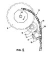
- This has a number of protuberances (18) on its periphery, suitably spaced so that the extensions (19) of the slats (20) of a blind (21) fit between them when these extensions move linearly or along conventional guides, not shown. See Figures 1 and 2.
- the freeing sector (5) has a slot (34) into which one of the stops (10) on the brake spring (9) fits in order to reduce the free play during operation to the minimum.
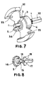
- Figure 6 shows a commercial freewheel mechanism used in the preferred embodiment, which appears as a conventional needle bearing.
- An asymmetric separator not visible, allows the needles to rotate with respect to the outer bush (3) in one direction (that of freewheeling) but not in the other direction.
- Figures 7 and 8 show perspective views of the arrangement of the first freewheel mechanism (2) and the second freewheel mechanism (15) on the drive shaft (1) and the locking shaft (16), respectively. Arrows in both figures show the relative movements allowed by the respective freewheel mechanisms.
- the drive shaft (1) rotates, by means of the square bar (22) the rolling drum (23) which frees the blind (21), allowing it to descend by gravity.
- the arrows show the rotational direction allowed by the freewheel mechanisms (2) (15) so that, as can be seen, the blind (21) can descend, freely turning the cogged wheel (17).
- the transmission pinion (14), the auxiliary crown (13), the auxiliary pinion (12) and the transmission crown (6) that form the transmission mechanism remain immobile since the locking sector (26) on the transmission crown (6) is retained by the stops (10) on the brake spring (9) which firmly presses against the brake cylinder (7), as can be seen in Figure 3.
- the first freewheel mechanism (2) remains locked so that the drive shaft (1) moves the drive cylinder (4) anti-clockwise and its freeing sector (5) turns the brake spring (9) in the direction that reduces its apparent diameter, which allows it to slip with respect to the brake cylinder (7).
- This small relative movement of the drive cylinder (4) with respect to the transmission crown (6) frees the ratchets (28), as shown in Figure 10, allowing the transmission crown (6) to turn which, through the auxiliary pinion (12), the auxiliary crown (13) and the transmission pinion (14), transmits the movement to the outer bush (3) of the second freewheel mechanism (15).
- the cogged wheel (17) must move upward at a speed determined by the sizes of the various elements in the transmission mechanism.
- the speed of movement of the cogged wheel (17) is defined by the blind (21) itself as it rolls up, to a value that is clearly less than that determined by the size of the transmission mechanism. That is, relative slippage occurs between the locking shaft (16) joined to the cogged wheel (17) and the transmission pinion (14), precisely in the direction allowed by the second freewheel mechanism (15).
- Figure 10 shows the large clearances C and D that appear between the crown and (6) and the drive cylinder (4) when the latter moves with respect to the former in the clockwise direction during the locking of the ratchets (28).
- Figure 11 shows how these clearances C and D are reduced until they almost disappear when the drive cylinder (4) moves with respect to the crown (6) in the anti-clockwise direction, which causes the unlocking of the ratchets (28). This small relative movement between both elements is what causes the locking or unlocking of the device.
Landscapes
- Engineering & Computer Science (AREA)
- Structural Engineering (AREA)
- Architecture (AREA)
- Civil Engineering (AREA)
- Operating, Guiding And Securing Of Roll- Type Closing Members (AREA)
- Blinds (AREA)
Applications Claiming Priority (1)
| Application Number | Priority Date | Filing Date | Title |
|---|---|---|---|
| ES200501490A ES2288073B1 (es) | 2005-06-17 | 2005-06-17 | Dispositivo autobloqueante perfeccionado para persianas y cierres. |
Publications (2)
| Publication Number | Publication Date |
|---|---|
| EP1734221A2 true EP1734221A2 (de) | 2006-12-20 |
| EP1734221A3 EP1734221A3 (de) | 2009-07-15 |
Family
ID=36954791
Family Applications (1)
| Application Number | Title | Priority Date | Filing Date |
|---|---|---|---|
| EP06380169A Withdrawn EP1734221A3 (de) | 2005-06-17 | 2006-06-14 | Verbessertes Selbstblockierungseinheit für Jalousien und Verschlüsse |
Country Status (5)
| Country | Link |
|---|---|
| US (1) | US7451799B2 (de) |
| EP (1) | EP1734221A3 (de) |
| AR (1) | AR057070A1 (de) |
| ES (1) | ES2288073B1 (de) |
| MX (1) | MXPA06006983A (de) |
Cited By (1)
| Publication number | Priority date | Publication date | Assignee | Title |
|---|---|---|---|---|
| CN113668999A (zh) * | 2021-08-02 | 2021-11-19 | 广州市晾百年科技有限公司 | 一种卷帘平衡自锁制尾组件及连接结构 |
Families Citing this family (7)
| Publication number | Priority date | Publication date | Assignee | Title |
|---|---|---|---|---|
| FR2889749B3 (fr) * | 2005-08-12 | 2007-06-22 | Guangzhou Grandview Crystal Sr | Mecanisme de deceleration et de blocage pour un ecran de projection et ecran de projection a commande manuelle utilisant ce mecanisme |
| US8371356B2 (en) * | 2008-08-26 | 2013-02-12 | Gary R. Manser | Garage door apparatus with folding door panels |
| EP3406831B1 (de) * | 2010-02-05 | 2019-06-26 | Magna Closures SpA | Fahrzeugverriegelung mit doppelklinkenanordnung |
| GB2508909B (en) * | 2012-12-14 | 2017-06-14 | System 2000 Group Ltd | Roller shutter |
| DE102014202471B3 (de) * | 2014-02-11 | 2015-04-30 | Hennig Holding Gmbh | Abdeckvorrichtung für Öffnungen, insbesondere für Maschinenöffnungen |
| CN113616065B (zh) * | 2021-09-18 | 2023-04-04 | 宁波公牛生活电器有限公司 | 电动轨道和电动窗帘 |
| TWI844335B (zh) * | 2023-04-17 | 2024-06-01 | 謝仲賢 | 兼具防壓及防盜功能之門機裝置及板門系統 |
Family Cites Families (20)
| Publication number | Priority date | Publication date | Assignee | Title |
|---|---|---|---|---|
| US541696A (en) * | 1895-06-25 | Flexible door | ||
| US705553A (en) * | 1901-05-06 | 1902-07-29 | Flexible Door And Shutter Company | Flexible door. |
| GB190909567A (en) * | 1909-04-22 | 1909-12-23 | Julius Mueller | Locking Device for Blinds. |
| US4108393A (en) * | 1976-08-16 | 1978-08-22 | American Safety Equipment Corporation | Emergency locking retractor with comfort belt tension |
| US4128120A (en) * | 1977-08-17 | 1978-12-05 | Interroyal Corporation | Tambour door and housing assembly |
| US4476910A (en) * | 1981-02-10 | 1984-10-16 | Kabushiki Kaisha Nichibei | Roll-blind |
| FR2584130B1 (fr) * | 1985-06-28 | 1988-07-15 | Schlagmuller Paul | Volet roulant de protection pour ouvertures dans les murs |
| CH669636A5 (de) * | 1985-09-10 | 1989-03-31 | Hartmann & Co Ag | |
| DE3811704A1 (de) * | 1988-04-08 | 1989-10-19 | Henkenjohann Johann | Antrieb fuer einen oeffnungsabschluss wie tor oder tuer aus gelenkig miteinander verbundenen lamellen |
| AT397979B (de) * | 1991-11-15 | 1994-08-25 | Kraler Franz | Rolladen |
| US5494093A (en) * | 1994-06-14 | 1996-02-27 | Wayne-Dalton Corp. | Rolling door stop apparatus |
| ATE194206T1 (de) * | 1995-04-12 | 2000-07-15 | Ceraper S L | Reversible lattenverschlussvorrichtung |
| DE19610432C2 (de) * | 1996-03-16 | 1999-07-01 | Roto Frank Ag | Getriebe für einen Rolladen, eine Jalousie oder dergleichen |
| US5931212A (en) * | 1997-07-15 | 1999-08-03 | Wayne-Dalton Corp. | Motorized operator for doors |
| JP3524738B2 (ja) * | 1997-11-27 | 2004-05-10 | 株式会社ニチベイ | ロールスクリーン |
| CA2352620A1 (en) * | 2001-07-06 | 2003-01-06 | Pierre-Louis Foucault | Anti-back drive chain hoist |
| US6640496B2 (en) * | 2001-09-06 | 2003-11-04 | Wayne-Dalton Corp. | Anti-drop device |
| US6637575B2 (en) * | 2001-10-03 | 2003-10-28 | L & P Property Management Company | Apparatus and method for thin profile ratchet actuator |
| DE10216845B4 (de) * | 2002-04-16 | 2005-06-30 | Atoma International Corp. Germany | Schloss, insbesondere Kraftfahrzeug-Heckschloss |
| ES2263337B1 (es) | 2004-06-30 | 2007-11-01 | Miguel Emper Sanchez | Dispositivo autobloqueante para persianas y cierres. |
-
2005
- 2005-06-17 ES ES200501490A patent/ES2288073B1/es not_active Expired - Fee Related
-
2006
- 2006-06-13 US US11/451,831 patent/US7451799B2/en not_active Expired - Fee Related
- 2006-06-14 EP EP06380169A patent/EP1734221A3/de not_active Withdrawn
- 2006-06-15 AR ARP060102539A patent/AR057070A1/es unknown
- 2006-06-16 MX MXPA06006983A patent/MXPA06006983A/es not_active Application Discontinuation
Cited By (1)
| Publication number | Priority date | Publication date | Assignee | Title |
|---|---|---|---|---|
| CN113668999A (zh) * | 2021-08-02 | 2021-11-19 | 广州市晾百年科技有限公司 | 一种卷帘平衡自锁制尾组件及连接结构 |
Also Published As
| Publication number | Publication date |
|---|---|
| US7451799B2 (en) | 2008-11-18 |
| US20060283558A1 (en) | 2006-12-21 |
| ES2288073A1 (es) | 2007-12-16 |
| ES2288073B1 (es) | 2009-02-01 |
| EP1734221A3 (de) | 2009-07-15 |
| AR057070A1 (es) | 2007-11-14 |
| MXPA06006983A (es) | 2007-04-20 |
Similar Documents
| Publication | Publication Date | Title |
|---|---|---|
| EP3312374B1 (de) | Architektonische strukturabdeckung mit doppelmodus | |
| CA2547723C (en) | Child safe cord lock | |
| EP2057342B1 (de) | Antriebs- und montagesystem für ein rollo | |
| US7451799B2 (en) | Self-locking device for blinds and shutters | |
| CA2352620A1 (en) | Anti-back drive chain hoist | |
| EP0990764B1 (de) | Feststellvorrichtung | |
| EP1106761A1 (de) | Sicherheitsschloss für Türe | |
| US6092581A (en) | Safety blind for windows and doors | |
| US6059008A (en) | Braking device for shutter for building | |
| EP1612368A2 (de) | Selbstsverriegelnde Vorrichtung für Jalousien und Verschlüsse | |
| EP3902969B1 (de) | Betätigungsmechanismus für eine fensterabdeckung und fensterabdeckung | |
| CN115362306A (zh) | 行星齿轮箱系统 | |
| EP0671543B1 (de) | Gedämpfte Fangvorrichtung für Rolladen oder Jalousien | |
| KR20100135364A (ko) | 셔터의 수동개폐장치 | |
| EP1967685A1 (de) | Modulare Jalousie | |
| TWI844335B (zh) | 兼具防壓及防盜功能之門機裝置及板門系統 | |
| WO2006000028A1 (en) | Door controller and locking mechanism | |
| JP4676243B2 (ja) | 回転体 | |
| JP4184286B2 (ja) | シャッター装置のシャッターカーテン開閉装置 | |
| EP4047173A1 (de) | Automatische betätigungsvorrichtung für eine rolltür oder einen rollvorhang | |
| JP4182483B2 (ja) | シャッター装置におけるシャッターカーテンの持上げ防止装置 | |
| JPH09268866A (ja) | 建築用シャッターの制動装置 | |
| JPH0585996U (ja) | 建物用開閉体の開閉伝動機構 | |
| CA2477679A1 (en) | Spring break device | |
| HK1126265B (en) | Operating and mounting system for a window covering |
Legal Events
| Date | Code | Title | Description |
|---|---|---|---|
| PUAI | Public reference made under article 153(3) epc to a published international application that has entered the european phase |
Free format text: ORIGINAL CODE: 0009012 |
|
| AK | Designated contracting states |
Kind code of ref document: A2 Designated state(s): AT BE BG CH CY CZ DE DK EE ES FI FR GB GR HU IE IS IT LI LT LU LV MC NL PL PT RO SE SI SK TR |
|
| AX | Request for extension of the european patent |
Extension state: AL BA HR MK YU |
|
| PUAL | Search report despatched |
Free format text: ORIGINAL CODE: 0009013 |
|
| AK | Designated contracting states |
Kind code of ref document: A3 Designated state(s): AT BE BG CH CY CZ DE DK EE ES FI FR GB GR HU IE IS IT LI LT LU LV MC NL PL PT RO SE SI SK TR |
|
| AX | Request for extension of the european patent |
Extension state: AL BA HR MK RS |
|
| AKX | Designation fees paid | ||
| REG | Reference to a national code |
Ref country code: DE Ref legal event code: 8566 |
|
| RBV | Designated contracting states (corrected) |
Designated state(s): AT BE BG CH CY CZ LI |
|
| 17P | Request for examination filed |
Effective date: 20100422 |
|
| RBV | Designated contracting states (corrected) |
Designated state(s): AT BE BG CH CY CZ DE DK EE ES FI FR GB GR HU IE IS IT LI LT LU LV MC NL PL PT RO SE SI SK TR |
|
| RIC1 | Information provided on ipc code assigned before grant |
Ipc: E06B 9/86 20060101AFI20100729BHEP |
|
| GRAP | Despatch of communication of intention to grant a patent |
Free format text: ORIGINAL CODE: EPIDOSNIGR1 |
|
| STAA | Information on the status of an ep patent application or granted ep patent |
Free format text: STATUS: THE APPLICATION IS DEEMED TO BE WITHDRAWN |
|
| 18D | Application deemed to be withdrawn |
Effective date: 20110201 |