EP1734026A1 - Wanderbettverfahrenverfahren zur Herstellung von Phenylakanen - Google Patents
Wanderbettverfahrenverfahren zur Herstellung von Phenylakanen Download PDFInfo
- Publication number
- EP1734026A1 EP1734026A1 EP06290804A EP06290804A EP1734026A1 EP 1734026 A1 EP1734026 A1 EP 1734026A1 EP 06290804 A EP06290804 A EP 06290804A EP 06290804 A EP06290804 A EP 06290804A EP 1734026 A1 EP1734026 A1 EP 1734026A1
- Authority
- EP
- European Patent Office
- Prior art keywords
- catalyst
- zone
- aromatic compound
- alkylation
- reaction
- Prior art date
- Legal status (The legal status is an assumption and is not a legal conclusion. Google has not performed a legal analysis and makes no representation as to the accuracy of the status listed.)
- Granted
Links
Images
Classifications
-
- B—PERFORMING OPERATIONS; TRANSPORTING
- B01—PHYSICAL OR CHEMICAL PROCESSES OR APPARATUS IN GENERAL
- B01J—CHEMICAL OR PHYSICAL PROCESSES, e.g. CATALYSIS OR COLLOID CHEMISTRY; THEIR RELEVANT APPARATUS
- B01J8/00—Chemical or physical processes in general, conducted in the presence of fluids and solid particles; Apparatus for such processes
- B01J8/08—Chemical or physical processes in general, conducted in the presence of fluids and solid particles; Apparatus for such processes with moving particles
- B01J8/12—Chemical or physical processes in general, conducted in the presence of fluids and solid particles; Apparatus for such processes with moving particles moved by gravity in a downward flow
-
- B—PERFORMING OPERATIONS; TRANSPORTING
- B01—PHYSICAL OR CHEMICAL PROCESSES OR APPARATUS IN GENERAL
- B01J—CHEMICAL OR PHYSICAL PROCESSES, e.g. CATALYSIS OR COLLOID CHEMISTRY; THEIR RELEVANT APPARATUS
- B01J35/00—Catalysts, in general, characterised by their form or physical properties
- B01J35/40—Catalysts, in general, characterised by their form or physical properties characterised by dimensions, e.g. grain size
-
- B—PERFORMING OPERATIONS; TRANSPORTING
- B01—PHYSICAL OR CHEMICAL PROCESSES OR APPARATUS IN GENERAL
- B01J—CHEMICAL OR PHYSICAL PROCESSES, e.g. CATALYSIS OR COLLOID CHEMISTRY; THEIR RELEVANT APPARATUS
- B01J38/00—Regeneration or reactivation of catalysts, in general
- B01J38/04—Gas or vapour treating; Treating by using liquids vaporisable upon contacting spent catalyst
- B01J38/12—Treating with free oxygen-containing gas
- B01J38/22—Moving bed, e.g. vertically or horizontally moving bulk
- B01J38/28—Moving bed, e.g. vertically or horizontally moving bulk having mainly concurrent flow of oxygen-containing gas and material
-
- B—PERFORMING OPERATIONS; TRANSPORTING
- B01—PHYSICAL OR CHEMICAL PROCESSES OR APPARATUS IN GENERAL
- B01J—CHEMICAL OR PHYSICAL PROCESSES, e.g. CATALYSIS OR COLLOID CHEMISTRY; THEIR RELEVANT APPARATUS
- B01J38/00—Regeneration or reactivation of catalysts, in general
- B01J38/48—Liquid treating or treating in liquid phase, e.g. dissolved or suspended
- B01J38/50—Liquid treating or treating in liquid phase, e.g. dissolved or suspended using organic liquids
- B01J38/56—Hydrocarbons
-
- C—CHEMISTRY; METALLURGY
- C07—ORGANIC CHEMISTRY
- C07C—ACYCLIC OR CARBOCYCLIC COMPOUNDS
- C07C2/00—Preparation of hydrocarbons from hydrocarbons containing a smaller number of carbon atoms
- C07C2/54—Preparation of hydrocarbons from hydrocarbons containing a smaller number of carbon atoms by addition of unsaturated hydrocarbons to saturated hydrocarbons or to hydrocarbons containing a six-membered aromatic ring with no unsaturation outside the aromatic ring
- C07C2/64—Addition to a carbon atom of a six-membered aromatic ring
- C07C2/66—Catalytic processes
-
- B—PERFORMING OPERATIONS; TRANSPORTING
- B01—PHYSICAL OR CHEMICAL PROCESSES OR APPARATUS IN GENERAL
- B01J—CHEMICAL OR PHYSICAL PROCESSES, e.g. CATALYSIS OR COLLOID CHEMISTRY; THEIR RELEVANT APPARATUS
- B01J2208/00—Processes carried out in the presence of solid particles; Reactors therefor
- B01J2208/00008—Controlling the process
- B01J2208/00017—Controlling the temperature
- B01J2208/00106—Controlling the temperature by indirect heat exchange
- B01J2208/00265—Part of all of the reactants being heated or cooled outside the reactor while recycling
- B01J2208/00292—Part of all of the reactants being heated or cooled outside the reactor while recycling involving reactant solids
-
- B—PERFORMING OPERATIONS; TRANSPORTING
- B01—PHYSICAL OR CHEMICAL PROCESSES OR APPARATUS IN GENERAL
- B01J—CHEMICAL OR PHYSICAL PROCESSES, e.g. CATALYSIS OR COLLOID CHEMISTRY; THEIR RELEVANT APPARATUS
- B01J2219/00—Chemical, physical or physico-chemical processes in general; Their relevant apparatus
- B01J2219/00002—Chemical plants
- B01J2219/00027—Process aspects
- B01J2219/0004—Processes in series
-
- B—PERFORMING OPERATIONS; TRANSPORTING
- B01—PHYSICAL OR CHEMICAL PROCESSES OR APPARATUS IN GENERAL
- B01J—CHEMICAL OR PHYSICAL PROCESSES, e.g. CATALYSIS OR COLLOID CHEMISTRY; THEIR RELEVANT APPARATUS
- B01J29/00—Catalysts comprising molecular sieves
- B01J29/04—Catalysts comprising molecular sieves having base-exchange properties, e.g. crystalline zeolites
- B01J29/06—Crystalline aluminosilicate zeolites; Isomorphous compounds thereof
- B01J29/08—Crystalline aluminosilicate zeolites; Isomorphous compounds thereof of the faujasite type, e.g. type X or Y
- B01J29/084—Y-type faujasite
-
- B—PERFORMING OPERATIONS; TRANSPORTING
- B01—PHYSICAL OR CHEMICAL PROCESSES OR APPARATUS IN GENERAL
- B01J—CHEMICAL OR PHYSICAL PROCESSES, e.g. CATALYSIS OR COLLOID CHEMISTRY; THEIR RELEVANT APPARATUS
- B01J29/00—Catalysts comprising molecular sieves
- B01J29/90—Regeneration or reactivation
-
- C—CHEMISTRY; METALLURGY
- C07—ORGANIC CHEMISTRY
- C07C—ACYCLIC OR CARBOCYCLIC COMPOUNDS
- C07C2529/00—Catalysts comprising molecular sieves
- C07C2529/04—Catalysts comprising molecular sieves having base-exchange properties, e.g. crystalline zeolites, pillared clays
- C07C2529/06—Crystalline aluminosilicate zeolites; Isomorphous compounds thereof
- C07C2529/08—Crystalline aluminosilicate zeolites; Isomorphous compounds thereof of the faujasite type, e.g. type X or Y
-
- C—CHEMISTRY; METALLURGY
- C07—ORGANIC CHEMISTRY
- C07C—ACYCLIC OR CARBOCYCLIC COMPOUNDS
- C07C2529/00—Catalysts comprising molecular sieves
- C07C2529/04—Catalysts comprising molecular sieves having base-exchange properties, e.g. crystalline zeolites, pillared clays
- C07C2529/06—Crystalline aluminosilicate zeolites; Isomorphous compounds thereof
- C07C2529/18—Crystalline aluminosilicate zeolites; Isomorphous compounds thereof of the mordenite type
-
- C—CHEMISTRY; METALLURGY
- C07—ORGANIC CHEMISTRY
- C07C—ACYCLIC OR CARBOCYCLIC COMPOUNDS
- C07C2529/00—Catalysts comprising molecular sieves
- C07C2529/04—Catalysts comprising molecular sieves having base-exchange properties, e.g. crystalline zeolites, pillared clays
- C07C2529/06—Crystalline aluminosilicate zeolites; Isomorphous compounds thereof
- C07C2529/70—Crystalline aluminosilicate zeolites; Isomorphous compounds thereof of types characterised by their specific structure not provided for in groups C07C2529/08 - C07C2529/65
-
- Y—GENERAL TAGGING OF NEW TECHNOLOGICAL DEVELOPMENTS; GENERAL TAGGING OF CROSS-SECTIONAL TECHNOLOGIES SPANNING OVER SEVERAL SECTIONS OF THE IPC; TECHNICAL SUBJECTS COVERED BY FORMER USPC CROSS-REFERENCE ART COLLECTIONS [XRACs] AND DIGESTS
- Y02—TECHNOLOGIES OR APPLICATIONS FOR MITIGATION OR ADAPTATION AGAINST CLIMATE CHANGE
- Y02P—CLIMATE CHANGE MITIGATION TECHNOLOGIES IN THE PRODUCTION OR PROCESSING OF GOODS
- Y02P20/00—Technologies relating to chemical industry
- Y02P20/50—Improvements relating to the production of bulk chemicals
- Y02P20/584—Recycling of catalysts
-
- Y—GENERAL TAGGING OF NEW TECHNOLOGICAL DEVELOPMENTS; GENERAL TAGGING OF CROSS-SECTIONAL TECHNOLOGIES SPANNING OVER SEVERAL SECTIONS OF THE IPC; TECHNICAL SUBJECTS COVERED BY FORMER USPC CROSS-REFERENCE ART COLLECTIONS [XRACs] AND DIGESTS
- Y10—TECHNICAL SUBJECTS COVERED BY FORMER USPC
- Y10S—TECHNICAL SUBJECTS COVERED BY FORMER USPC CROSS-REFERENCE ART COLLECTIONS [XRACs] AND DIGESTS
- Y10S585/00—Chemistry of hydrocarbon compounds
- Y10S585/8995—Catalyst and recycle considerations
- Y10S585/901—Catalyst and recycle considerations with recycle, rehabilitation, or preservation of solvent, diluent, or mass action agent
Definitions
- the present invention relates to a process for the production of phenylalkanes by catalytic alkylation of an aromatic compound by means of olefinic hydrocarbons generally comprising from 9 to 16 atoms, and preferably from 10 to 14 carbon atoms per molecule.
- the phenylalkanes obtained according to the process of the invention are precursors of choice for the formulation of detergents, and in particular certain biodegradable detergents, for example after sulphonation.
- biodegradable detergent bases rely heavily on alkylbenzenes or phenylalkanes.
- the production of this type of compounds is steadily increasing.
- One of the main properties sought for these compounds is their biodegradability which requires that the said compounds be linear alkylbenzenes (LAB) or slightly branched (MAB), according to the definition of the patent. US6187981 .
- the alkylbenzenes are generally obtained by alkylation of benzene using olefins generally having 9 to 16 carbon atoms.
- Acidic acid catalysts are an interesting alternative to the use of prior acid catalysts.
- the major drawback of acidic solid catalysts is their rapid deactivation during the adsorption alkylation reaction on the surface of said heavy hydrocarbon species catalysts, often referred to generally by those skilled in the art as coke.
- the patent US 2,541,044 claims a continuous alkylation process employing several reactors operating in parallel with periodic switching of each reactor from the alkylation reaction phase to a catalyst rejuvenation phase taking place at high temperature using an alkylated hydrocarbon stream.
- patent US 5,648,579 discloses a continuous alkylation process in the presence of an acidic solid catalyst whose level of activity is maintained by alternately proceeding an alkylation reaction step (benzene + olefins) and a benzene washing step during which the olefins flow is interrupted for a cycle time of 10 minutes to 1 hour.
- the patent US 5,453,553 discloses a process for producing linear alkylbenzenes in the presence of hydrogen using a solid catalyst comprising a metal phase in close contact with a zeolite.
- the method for producing continuous phenylalkanes uses at least one reactor operating in a moving bed, said reactor being divided into several reaction zones traveled in series by the feedstock and the effluents, each zone being able to operate with a same or different catalyst, and said catalyst being sent continuously in a rejuvenation circuit, and sequentially in a regeneration circuit.
- the novelty of the present invention lies in the application of the moving bed technology to the alkylation reaction of an aromatic compound, the reactor used being divided into several reaction zones with staging of the feed in each of the reaction zones. and each zone having a rejuvenation circuit and a regeneration circuit, said circuits being able in certain cases to be common to several reaction zones.
- the catalyst In the moving bed processes, the catalyst is generally in the form of approximately spherical particles, of the order of a millimeter in size, and travels the reactor in downward flow at linear speeds of the order of one meter per hour.
- the catalytic reforming type moving bed processes use one or more reactors operating in series with a catalyst regeneration circuit common to all the reactors.
- the term series means that each reactor in the series is fed with the spent catalyst from the previous reactor.
- the reactor according to the invention is divided into several reaction zones each comprising a catalyst which may be identical or different from one zone to another.
- the catalyst of a given zone is taken continuously at the outlet of said zone to be introduced into the rejuvenation circuit, then after rejuvenation it is reintroduced at the head of the zone from which it was taken.
- the catalyst of the zone in question is sent into the regeneration circuit, and then the regenerated catalyst is reintroduced at the head of the zone from which it was taken.
- the rejuvenation circuit will be common for the different reaction zones.
- each reaction zone may optionally have its own rejuvenating circuit. This is particularly the case for reaction zones having different catalysts. It is the person skilled in the art who, according to the economic constraints or the ease of operation, will choose the best possible configuration of the process in terms of decomposition of the reactor into a plurality of reaction zones, of a rejuvenation circuit and of a regeneration circuit.
- the regeneration circuit may be common to several zones since regeneration of the catalyst of several zones is generally not carried out simultaneously.
- the catalyst of one zone does not circulate in another zone.
- a configuration in which a number of zones are traversed in series by the same catalyst remains perfectly within the scope of the invention.
- the subset of the zones traversed in series by the same catalyst has a rejuvenation circuit common to all of said zones, the catalyst being continuously withdrawn at the outlet of the last zone, then after rejuvenation is reintroduced into head of the first zone of the said series.
- the reactor according to the invention may comprise only reaction zones without circulation from one area to another.
- the present invention discloses a process for producing moving bed phenylalkanes using at least one reactor divided into a plurality of reaction zones, staggering the introduction of the olefinic feed into each of the reaction zones, and reactivating the catalyst by means of a rejuvenation circuit operating continuously, and a regeneration circuit operating sequentially.
- the regeneration could also be done continuously while remaining within the scope of the invention, but because of the existence of a rejuvenation circuit operating continuously, the regeneration circuit will work in the great majority of cases sequentially at an optimized frequency.
- the present invention furthermore describes a process for producing phenylalkanes whose selectivity to linear or branched products, and more generally, the concentration of the 2-phenyl isomer, can be controlled by appropriate choice of the catalyst used in each reaction zone.
- the present invention therefore consists of a process for producing phenylalkanes by alkylation of an aromatic compound, by at least one olefin having from 9 to 16 carbon atoms per molecule, and preferably having from 10 to 14 carbon atoms per molecule, said reaction being carried out in at least one reactor divided into a plurality of reaction zones, each reaction zone operating in a moving bed with an acidic solid catalyst.
- the aromatic charge is introduced entirely at the top of the first reaction zone, and the olefinic feed is introduced in the form of fractions in each of the reaction zones.
- the olefins used as alkylating agent in the alkylation catalytic reactor (s) according to the invention preferably contain from 10 to 14 carbon atoms per molecule.
- the olefins used for the alkylation reaction are predominantly linear, that is to say that preferably the linear olefins represent at least 50% by weight of the olefinic feedstock entering each reaction zone and preferably at least 60% by weight. of said load.
- the olefinic feedstock comes from a dehydrogenation unit effluent of n-paraffins, it may contain up to 20% by weight of heavy aromatics formed in the dehydrogenation unit, in addition to the linear paraffins. unconverted and olefins.
- the aromatic compound used as reagent in the alkylation catalytic reactor (s) is preferably benzene
- the different reaction zones operate in series from the point of view of charge / effluent, in that the supply of the reaction zone n consists of the olefinic alkylation charge fraction, the effluents of the reaction zone n-1, and optionally a fraction of aromatic compound to be alkylated.
- the catalyst of each reaction zone is taken at the outlet of said zone, directed continuously towards a rejuvenation zone, and is then reintroduced at the top of said reaction zone.
- reaction zones forming a sub-series are traversed in series by the same catalyst, said catalyst being then taken out of the last zone of the sub-series, introduced into the rejuvenation circuit common to the zones of said sub-series, and reintroduced after rejuvenation at the top of the first reaction zone of said sub-series.
- the catalyst of each reaction zone is taken at the outlet of said zone, introduced into the regeneration circuit, then generally passes into the rejuvenation circuit, and is reintroduced at the top. of the reaction zone considered.
- the rejuvenation circuit is characterized by washing the catalyst with a stream of aromatic hydrocarbons, usually benzene.
- the regeneration circuit is characterized by a controlled combustion of the hydrocarbon compounds adsorbed on the surface of the catalyst.
- the regeneration zone can be operated also in a moving bed or in a fixed bed, at a pressure generally close to the average process pressure and at a temperature generally between 400 ° C. and 650 ° C.
- the regeneration zone can optionally be operated at a lower pressure by means of a buffer tank between the separator and the regenerator.
- the catalyst which has undergone reactivation, by rejuvenation and / or by regeneration, is then transferred by lift or by gravity flow depending on the geometry of the installation, towards the inlet of the reaction zone in which it works, or entry of the series of reaction zones if a plurality of reaction zones are affected by the same catalyst.
- the catalyst can flow in co-current with respect to the charge, or cross-flow.
- the feedstock is introduced at the periphery of the reaction zone in question and is then collected in a central well situated approximately in the center of the said reaction zone.
- patents US 3,838,039 , US5,336,829 , US 5,849,976 and to the patent application EP 1 195 424A1 . Reverse circulation of the charge from the reactor center to the periphery is also possible.
- the process according to the invention also has the advantage of producing phenylalkanes whose selectivity in linear products, that is to say having no branching on the alkyl chain carried by the benzene group, and particularly the selectivity to 2-phenyl, is controllable, which is interesting because the specifications of the products sought for an application in the formulation of detergents are "very variable".
- Another advantage of the invention is the optimization of the amount of olefinic feedstock to be introduced into the various reaction zones of the catalytic reactor (s).
- the process according to the invention makes it possible, by fractionation of the olefinic feedstock, to reduce the amount of benzene required with respect to previous processes, while maintaining the same composite report (s) aromatic (s) / olefins, preferably benzene / olefins, in the catalytic reactor (s).
- This possibility of modulating the aromatic / olefin ratio represents a saving in terms of the initial investment, the operating cost, and makes it possible, in combination with the continuous rejuvenation of the catalyst, to considerably increase the lifetime of said catalyst.
- the process according to the invention does not require the elimination, upstream of the alkylation reactor (s), of the coke precursor compounds responsible for the deactivation, that is to say essentially heavy aromatics derived for example from a dehydrogenation unit.
- the continuous rejuvenation of the catalyst makes it possible to tolerate these heavy aromatic compounds in the alkylation feed up to levels of 80% in the olefin feedstock, the said percentage being referred to only olefinic and aromatic compounds (this is ie excluding other compounds present in the alkylation charge, such as normal paraffins).
- the frequency of the regeneration will be mainly conditioned by the content of these aromatic compounds, precursors of the deactivation, in the alkylation charge.
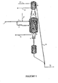
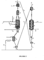
- FIGS. 1 and 2 are represented respectively the circuit of the feedstock and the effluents, the catalyst circuit for the rejuvenation circuit (FIG. 1), and the catalyst circuit for the reactor. regeneration circuit (FIG. 2) with a number of reaction zones n equal to 2.
- the installation making it possible to carry out the process for producing phenylalkanes according to the invention therefore comprises at least one alkylation catalytic reactor (4), a rejuvenation flask (28) and a regeneration flask (11), hereinafter called regenerator (11).
- the reactor (4) is divided into two reaction zones, an upper reaction zone (A) and a lower reaction zone (B), each provided with means for introducing the catalyst (48) and withdrawing (39) for the reaction zone.
- the withdrawal means further comprise at least one reservoir (45) fed from an intermediate pot (7) for directing the catalyst to the rejuvenation circuit, and a reservoir (46) fed from an intermediate pot (8) for directing the catalyst to the regeneration circuit. Intermediate pots (7) and (8) may possibly be confused.
- the olefinic feed (1) is divided into a fraction (2) supplying the reaction zone A, and a fraction (3) supplying the reaction zone B.
- the olefinic feedstock fraction (2) is mixed with the aromatic compound introduced integrally via line (41) to form the charge of the reaction zone A.
- the olefinic feedstock fraction (3) is mixed with the effluents from the reaction zone A (not shown in the figures) to form the feedstock for the reaction zone B.
- reaction effluents of the reaction zone B are removed from said zone by the line (14) where they are directed to a fractionation zone not shown in FIGS. 1 and 2.
- the number n of reaction zones of each reactor is between 1 and 10, and preferably between 1 and 5.
- a fraction of the total amount of olefins required for the alkylation reaction of the aromatic compound, preferably benzene, is introduced at the inlet of each of the reaction zones so that the ratio of the weight of aromatic to alkylated on the the weight of olefins at the inlet of each reaction zone is between 30 and 100, and preferably between 30 and 70.
- the olefin fraction introduced at the inlet of each of the reaction zones is such that the aromatic weight ratio to alkylate on olefins is staggered in the increasing or decreasing direction, in each of said reaction zones. That is to say that this ratio can be increased (or decreased) according to a certain progression, when passing from the reaction zone of rank n to the reaction zone of rank n + 1 for reasons of product quality or stability catalyst.
- the previously mentioned ratio can also be modified by adjusting the fraction of the aromatic compound to be alkylated when it is fractionally introduced.
- Each olefinic feed fraction is generally contained in a hydrocarbon feed containing mainly paraffins.
- the paraffins contained in said feed are paraffins C 9 -C 16 , preferably C 10 -C 14 .
- the olefins generally represent from 5 to 100% by weight of the hydrocarbon feedstock introduced at the inlet of each of the reaction zones.
- Each of the reaction zones is operated at a temperature below 400 ° C., generally between 50 ° C. and 350 ° C., preferably between 70 ° C. and 300 ° C., and more preferably between 80 ° C. and 250 ° C.
- the alkylation reaction carried out in the alkylation catalytic reactor (s) according to the invention is generally followed by at least one separation step in order to recover the excess reagents on the one hand, and the desired phenylalkanes from somewhere else.
- the catalyst is transported by a liquid lift (25) fed by a liquid flow (26) (a gaseous lift being also possible, in this case by draining the balloon (45)), to a balloon rejuvenation (28) located for example above the alkylation reactor (4), and then washing said catalyst at least partially deactivated by an aromatic compound introduced via line (30).
- the washing effluents containing the aromatic washing compound and the hydrocarbons adsorbed on the catalyst surface are discharged from the rejuvenation flask (28) via the line (31).
- the rejuvenated catalyst is reintroduced at the top of the reaction zone A by means of the legs (48).
- said aromatic compound is benzene.
- the rejuvenation is carried out in the absence of olefinic hydrocarbons since, generally, the catalyst before transport undergoes a separation step of the reaction effluents at the level of the flask (45).
- the temperature at which the rejuvenation is carried out is generally greater than 100 ° C, more preferably greater than 150 ° C, and more preferably greater than 200 ° C.
- the rejuvenation is carried out for a sufficient time, so as to ensure complete removal of the adsorbed hydrocarbons in the active sites of each of the acidic solid catalysts. This time depends on the deactivation level of the catalyst, but also on the hydrodynamic conditions used in the rejuvenation flask (28) during washing, in particular the linear speed of the washing agent which will generally be greater than 1 m / s.
- the catalyst withdrawn continuously from the rejuvenation flask (28) by means of the descent legs (48) is sent, generally by gravity, to the reaction zone from which it was taken (zone A in FIG. 1).
- the rejuvenated catalyst is reintroduced at the top of the first reaction zone. of said sub-series.
- the regeneration consists of transferring the catalyst from the reaction zone (noted B in FIG. 2) to a flask (46) via the legs (37) and the intermediate pot (8), and then to transfer the catalyst from the flask ( 46) to the lift pot (6) from which it is transported by means of the transport gas (15) to a separator tank (10) from which it is transferred by gravity to the regenerator (11).
- the separator balloon (10) allows the separation of the catalyst and the transport gas, and the elimination of any fine particles formed by attrition during said transport.
- the catalyst undergoes a controlled combustion of the hydrocarbon species adsorbed on its surface, by means of a combustion gas introduced via the line (40).
- the combustion effluents are evacuated via the line (29) to a specific regeneration circuit known to those skilled in the art.
- the regenerated catalyst is transferred to an intermediate pot (38), then the intermediate pot (38), it is taken up in the transport pot (12), fed by the transport gas (27) to be returned to a separating drum ( 13) inside which the catalyst is separated from the transport gas and the fine particles possibly formed during said transport.
- the regenerated catalyst leaving the separator flask (13) is reintroduced into the rejuvenation flask (28) before being returned via the legs (36) to the reaction zone B.
- the reaction zone in which the regenerated catalyst is reintroduced may be either the reaction zone from which it was taken or the first reaction zone of a subset of reaction zones using the same catalyst as defined in the description paragraph. of the invention.
- the regeneration is carried out by combustion of the hydrocarbon species adsorbed on the active sites of the catalyst.
- the first stage of heating under inert gas makes it possible to avoid any risk of uncontrolled temperature rise during the second stage, which corresponds to the actual combustion of the coke.
- the majority of the coke is burned during the combustion stage.
- the weight content of residual coke on the catalyst after combustion is generally less than 20%, and preferably less than 10% of the coke content on the catalyst before said combustion.
- the oxygen-containing gas used during the combustion step is generally a mixture of oxygen and inert gas, preferably containing from 0.1% to 20% by volume of oxygen, and preferably from 0, 2% to 10% by volume of oxygen.
- It may be for example air, or air diluted in an inert gas.
- Regeneration is triggered at time periods determined from indicators generally placed in line, and which, directly or indirectly, reflect the degree of deactivation of the catalyst.
- the reactor for the production of phenyl alkanes by alkylation of an aromatic compound with an olefinic feed consists of a series of n reaction zones, each reaction zone having at least one thermocouple measuring the temperature at the inlet and outlet of said zone, and the regeneration sequence of the catalyst contained in said zone being triggered when the temperature difference between the outlet and the inlet of said zone exceeds a certain value.
- the catalyst comprises at least one zeolite selected from the group consisting of structural type zeolites FAU, MOR, MTW, OFF, MAZ, BEA EUO, UTL and NES.
- the catalyst contained in each, or at least part of the reaction zones comprises at least one Y zeolite, advantageously a dealuminated Y zeolite, having an overall Si / Al atomic ratio greater than 4, preferably between 8 and 100. and more preferably between 15 and 70.
- a mixture of catalysts may be for example a mixture of a crystallized catalyst and an amorphous catalyst. It may also be a mixture of zeolites consisting of at least one zeolite Y as described above, and at least one zeolite of structural type MOR, in particular a zeolite mordenite.
- the process for producing phenyl alkanes by alkylation of an aromatic compound according to the invention may contain in certain reaction zones a crystalline acidic solid catalyst of structural type chosen from the group formed by FAU, MOR, MTW, OFF, MAZ, BEA. EUO, UTL and NES.
- the catalyst used in at least part of the reaction zones may also be an amorphous solid catalyst chosen from the group formed by silica aluminas, and alumina doped or not with halogenated compounds.
- the process for producing phenyl alkanes by alkylation of an aromatic compound according to the invention may contain in certain reaction zones a mixture of at least two crystalline solid catalysts of structural type selected from the group consisting of FAU, MOR, MTW, OFF, MAZ, BEA EUO, UTL and NES.
- the process for producing phenylalkanes according to the invention may contain, in certain reaction zones, a mixture of at least one crystallized solid catalyst of structural type chosen from the group formed by FAU, MOR, MTW, OFF, MAZ, BEA. EUO, UTL, NES and an amorphous solid catalyst selected from the group formed by silica aluminas, and alumina doped or not with halogenated compounds.
- the mixture of said zeolites in the form of powder can be achieved by all the powder mixing techniques known to those skilled in the art, and followed by shaping.
- the mixture can in particular be made with a matrix, generally amorphous, or with a moist powder of alumina gel.
- the shaping can also be carried out with other matrices than alumina, such as, for example, magnesia, amorphous silica-aluminas, natural clays (kaolin, bentonite, sepiolite, attapulgite), silica, oxide titanium, boron oxide, zirconia, aluminum phosphates, titanium phosphates, zirconium phosphates, coal and mixtures thereof.
- matrices containing alumina in all the forms known to those skilled in the art, and even more preferably containing gamma-alumina.
- the catalyst contained in each of the reaction zones of the alkylation catalytic reactor or reactors for carrying out the process according to the invention is formed into grains of shape and size compatible with the different modes of transport used in the present invention. invention.
- the catalyst that must circulate inside the reaction zones in a moving bed is most often in the form of spherical balls with a ball diameter of a few millimeters, typically from 0.5 to 5 mm, and preferably from 1 to 4 mm.
- the manufacture of the catalyst it is possible to use conventional techniques, for example mixing the zeolite with precursors of silica gel and / or silica gels, then shaping small beads by coagulating drops, drying and then calcining the said beads to obtain the final catalyst of the appropriate shape and size.
- the solid obtained is subjected to a drying step at a temperature between 100 and 300 ° C, preferably between 120 and 200 ° C, and then at a calcination step at a temperature between 300 and 600 ° C, preferably between 350 and 550 °.
- the alkylation reactor used comprises 2 reaction zones, an upper reaction zone denoted A, and a lower reaction zone denoted B. There is no circulation of catalyst from one zone to another.
- the catalyst used in the two zones consists of 70% by weight of zeolite Y dealuminated with an Si / Al ratio of 30.
- the size of the spherical catalyst particles is 2.5 mm.
- the olefinic alkylation charge (1) is divided into a first fraction (2) introduced into the first reaction zone (A) and a second fraction (3) introduced into the second reaction zone (B).
- the charge consisting of benzene (41) is mixed with the alkylation charge (1) and then introduced into the reaction zone (A) via line (2).
- the weight ratio benzene / olefin is equal to 60. All the benzene is introduced at the top of the reactor.
- the feed of the reaction zone (B) consists of the reaction effluent of the reaction zone (A) and the olefinic feed stream (3).
- reaction effluent is sent through line 14 to a separation section not shown in FIG. 1.
- Reaction zones A and B operate at a temperature of 120 ° C under a pressure of 4 MPa.
- the separation section comprises several fractionating columns, and is intended to separate the desired reaction products, ie mainly a mixture of 2-phenylalkane, 3-phenylalkane, 4-phenylalkane, 5-phenylalkane and 6-phenylalkane which is sent to storage.
- the catalyst of the reaction zones A and B is withdrawn respectively by the descent legs (39) and (37).
- the catalyst coming from the reaction zone (A) will be described as the rejuvenation circuit (see FIG. 1), and for the catalyst coming from the reaction zone (B) the circuit regeneration (see Figure 2).
- the preferred mode of operation of the present invention is to continuously rejuvenate the catalyst from reaction zone A and B in the same rejuvenation circuit (the catalysts of zones A and B being identical, and withdrawn in parallel. ), and sequentially to regenerate the catalyst from the reaction zones A and B in the same regeneration circuit. Rejuvenation and regeneration coexist in operation, each with their specific circuit.
- the catalyst from the reaction zone (A) is drawn off by the descent leg (39) and sent to an intermediate pot (7) and then to the flask (45) before being transferred via a liquid elevator (25) to the rejuvenation flask (28) fed with benzene at 250 ° C via line (30).
- the washing effluent containing the washing benzene and the products adsorbed on the surface of the catalyst are discharged through the line (31) and are sent to the separation section.
- the transport liquid supplying the liquid elevator (25) is introduced via the line (26).
- the rejuvenated catalyst is reintroduced at the top of the reaction zone (A) via descent legs (48).
- the rejuvenated catalyst is contacted in the reaction zone (A) with the alkylated benzene (41) and the olefinic feedstock (2).
- the catalyst from the reaction zone (B) is withdrawn by the descent leg (37), and sent into an intermediate pot (8) and into the flask (46) inside which it undergoes drainage, preheating and stripping to a temperature of 300 ° C by means of hot nitrogen introduced by the line (43).
- the catalyst is then transferred to a lift (6) to be conveyed via a lift gas (24) supplied with the transport nitrogen (15) to the upper hopper (10) above the regeneration flask (11). ).
- the catalyst is then led to the regenerator (11) where it undergoes a controlled combustion in the presence of air introduced by the line (40).
- the combustion gases are discharged from the regenerator (11) via line (29) and are sent to a specific regeneration circuit (not shown in FIG. 2).
- the regenerated catalyst passes into a hopper (38) and then into a lifting pot (12) in order to be conveyed into the upper hopper (13) by a pneumatic conveying system (23) operating at the same time. nitrogen (27).
- the catalyst is swept by a gas (31) for discharging any fines created during transport which are directed by the line (32) to a not shown particulate filter.
- the catalyst is transferred to the rejuvenation flask (28) where it is contacted with benzene, before being reintroduced into the reaction zone (B) of the reactor (4) by means of the descent legs (36).
- the regenerated catalyst is brought into contact with the reaction charge resulting from the olefinic feedstock (3), and effluents from the reaction zone (A).
- the catalyst flows gravitarily into the reaction zone (B) and is collected in the bottom in a hopper (46) via the pot (8).
Landscapes
- Chemical & Material Sciences (AREA)
- Organic Chemistry (AREA)
- Chemical Kinetics & Catalysis (AREA)
- Engineering & Computer Science (AREA)
- Materials Engineering (AREA)
- Organic Low-Molecular-Weight Compounds And Preparation Thereof (AREA)
- Low-Molecular Organic Synthesis Reactions Using Catalysts (AREA)
Applications Claiming Priority (1)
| Application Number | Priority Date | Filing Date | Title |
|---|---|---|---|
| FR0505993A FR2886936B1 (fr) | 2005-06-09 | 2005-06-09 | Procede de production de phenylalcanes fonctionnant en lit mobile |
Publications (2)
| Publication Number | Publication Date |
|---|---|
| EP1734026A1 true EP1734026A1 (de) | 2006-12-20 |
| EP1734026B1 EP1734026B1 (de) | 2009-09-30 |
Family
ID=35789112
Family Applications (1)
| Application Number | Title | Priority Date | Filing Date |
|---|---|---|---|
| EP06290804A Not-in-force EP1734026B1 (de) | 2005-06-09 | 2006-05-17 | Wanderbettverfahrenverfahren zur Herstellung von Phenylalkanen |
Country Status (5)
| Country | Link |
|---|---|
| US (1) | US7541505B2 (de) |
| EP (1) | EP1734026B1 (de) |
| DE (1) | DE602006009439D1 (de) |
| ES (1) | ES2332191T3 (de) |
| FR (1) | FR2886936B1 (de) |
Families Citing this family (5)
| Publication number | Priority date | Publication date | Assignee | Title |
|---|---|---|---|---|
| US8389787B1 (en) | 2012-03-21 | 2013-03-05 | Uop Llc | Control of 2-phenyl content in alkylbenzenes during production |
| FR2992326B1 (fr) | 2012-06-21 | 2014-06-20 | IFP Energies Nouvelles | Procede de production de tensio-actifs a partir de matieres renouvelables comprenant une etape d'hydrotraitement et une etape de transformation de paraffines en tensio-actifs |
| CN116554917A (zh) * | 2022-01-27 | 2023-08-08 | 中国石油化工股份有限公司 | 一种移动床固体酸烷基化连续反应系统及方法 |
| CN114950281B (zh) * | 2022-06-13 | 2023-09-22 | 清华大学 | 一种高效裂解c3-c9非芳烃制备芳烃的系统与方法 |
| CN116380272A (zh) * | 2023-05-24 | 2023-07-04 | 上海精普机电科技有限公司 | 烷基化装置专用耐高温腐蚀热电偶以及温度监控系统 |
Citations (6)
| Publication number | Priority date | Publication date | Assignee | Title |
|---|---|---|---|---|
| US4008291A (en) * | 1975-06-16 | 1977-02-15 | Universal Oil Products Company | Simulated moving bed alkylation process |
| US4301317A (en) * | 1979-11-20 | 1981-11-17 | Mobil Oil Corporation | Preparation of 2-phenylalkanes |
| US4973780A (en) * | 1988-04-27 | 1990-11-27 | Lummus Crest, Inc. | Alkylation of benzene in a moving bed |
| US5453553A (en) * | 1992-04-03 | 1995-09-26 | Council Of Scientific & Industrial Research | Process for the production of linear alkylbenzenes |
| EP0765849A1 (de) * | 1994-05-24 | 1997-04-02 | China Petro-Chemical Corporation | Alkylierung aromatisches kohlenwasserstoffe und eine fluessig-feste zirkulierende wirbelschicht zur alkylierung |
| US5675048A (en) * | 1994-10-14 | 1997-10-07 | Uop | Dual regeneration zone solid catalyst alkylation process |
Family Cites Families (1)
| Publication number | Priority date | Publication date | Assignee | Title |
|---|---|---|---|---|
| US5849976A (en) * | 1994-07-27 | 1998-12-15 | Uop Llc | Moving bed solid catalyst hydrocarbon alkylation process |
-
2005
- 2005-06-09 FR FR0505993A patent/FR2886936B1/fr not_active Expired - Fee Related
-
2006
- 2006-05-17 DE DE602006009439T patent/DE602006009439D1/de active Active
- 2006-05-17 EP EP06290804A patent/EP1734026B1/de not_active Not-in-force
- 2006-05-17 ES ES06290804T patent/ES2332191T3/es active Active
- 2006-06-08 US US11/448,680 patent/US7541505B2/en not_active Expired - Fee Related
Patent Citations (6)
| Publication number | Priority date | Publication date | Assignee | Title |
|---|---|---|---|---|
| US4008291A (en) * | 1975-06-16 | 1977-02-15 | Universal Oil Products Company | Simulated moving bed alkylation process |
| US4301317A (en) * | 1979-11-20 | 1981-11-17 | Mobil Oil Corporation | Preparation of 2-phenylalkanes |
| US4973780A (en) * | 1988-04-27 | 1990-11-27 | Lummus Crest, Inc. | Alkylation of benzene in a moving bed |
| US5453553A (en) * | 1992-04-03 | 1995-09-26 | Council Of Scientific & Industrial Research | Process for the production of linear alkylbenzenes |
| EP0765849A1 (de) * | 1994-05-24 | 1997-04-02 | China Petro-Chemical Corporation | Alkylierung aromatisches kohlenwasserstoffe und eine fluessig-feste zirkulierende wirbelschicht zur alkylierung |
| US5675048A (en) * | 1994-10-14 | 1997-10-07 | Uop | Dual regeneration zone solid catalyst alkylation process |
Also Published As
| Publication number | Publication date |
|---|---|
| FR2886936B1 (fr) | 2007-08-03 |
| DE602006009439D1 (de) | 2009-11-12 |
| US20060287562A1 (en) | 2006-12-21 |
| US7541505B2 (en) | 2009-06-02 |
| FR2886936A1 (fr) | 2006-12-15 |
| ES2332191T3 (es) | 2010-01-28 |
| EP1734026B1 (de) | 2009-09-30 |
Similar Documents
| Publication | Publication Date | Title |
|---|---|---|
| KR100818438B1 (ko) | 촉매 재활성화를 통한 알킬 방향족 화합물의 생산 | |
| RU2447052C2 (ru) | Способ получения фенилалканов с заданным содержанием 2-фенилов | |
| CN101605745A (zh) | 制备洗涤剂范围烷基苯的方法 | |
| FR2543153A1 (fr) | Procede de transformation d'hydrocarbures par reformage pour favoriser la production de composes aromatiques | |
| EP1242568A1 (de) | Verfahren zur herstellung von aromaten in wanderbett mit katalysator reduktion | |
| EP1668094B1 (de) | Verfahren zur direktumwandlung eines olefine mit mindestens vier oder fünf kohlenstoffatomen enthaltenden einsatzstoffs zur herstellung von propylen | |
| EP1661617B1 (de) | Festbett- oder Wanderbettreaktor mit mehreren Zonen und integriertem Wärmetauscher | |
| CA3102551A1 (fr) | Dispositif et procede de conversion de composes aromatiques par alkylation de benzene par l'ethanol | |
| EP1734026B1 (de) | Wanderbettverfahrenverfahren zur Herstellung von Phenylalkanen | |
| RU2243034C2 (ru) | Способ регенерации цеолитных катализаторов | |
| US8747785B2 (en) | Apparatus for the reduction of gasoline benzene content by alkylation with dilute ethylene | |
| EP0781831B1 (de) | Verfahren zur Erniedrigung des Gehaltes von Benzol und von leichten ungesättigten Verbindungen in Kohlenwasserstofffraktionen | |
| WO2006051185A1 (fr) | Dispositif reactionnel a plusieurs zones en lit mobile avec appoint dans chaque zone de catalyseur regenere ou frais | |
| EP1892229A1 (de) | Verfahren zur Herstellung von Propylen in Gegenwart eines makroporösen Katalysators in Form von sphärischen Kügelchen | |
| WO2008100802A1 (en) | Energy integrated processes for making detergent range alkylbenzenes | |
| CA2538186A1 (fr) | Procede d'hydrocraquage avec recyclage comprenant l'adsorption de composes polyaromatiques de la fraction recyclee sur adsorbant a base de silice-alumine a teneur limitee en macropores | |
| EP0688749B1 (de) | Verfahren zur Verjüngung eines festen Alkylierungskatalysators | |
| EP1637575A1 (de) | Wanderbettverfahren zur Produktion von Propylen mit Recycling von einer Fraktion des verwendeten Katalysators | |
| MXPA06008184A (es) | Sistema y metodo para fracturacion de componente selectivo para llevar al maximo la produccion de olefinas ligeras. | |
| FR2876099A1 (fr) | Procede de production de phenylalcanes mettant en oeuvre au moins deux reacteurs d'alkylation en parallele | |
| TWI331628B (en) | A process for hydrocarbon conversion with on-line solid particulate material removal | |
| FR2784686A1 (fr) | Procede d'isomerisation des composes aromatiques a huit atomes de carbone en deux etapes successives et utilisant un catalyseur active | |
| CN101039889B (zh) | 具有固体催化剂再生和芳族副产物脱除的烷基化芳族化合物的方法 | |
| FR2876098A1 (fr) | Procede de production de phenylalcanes mettant en oeuvre au moins deux reacteurs d'alkylation en parallele | |
| FR2777276A1 (fr) | Procede d'isomerisation des composes aromatiques a huit atomes de carbone en deux etapes successives |
Legal Events
| Date | Code | Title | Description |
|---|---|---|---|
| PUAI | Public reference made under article 153(3) epc to a published international application that has entered the european phase |
Free format text: ORIGINAL CODE: 0009012 |
|
| AK | Designated contracting states |
Kind code of ref document: A1 Designated state(s): AT BE BG CH CY CZ DE DK EE ES FI FR GB GR HU IE IS IT LI LT LU LV MC NL PL PT RO SE SI SK TR |
|
| AX | Request for extension of the european patent |
Extension state: AL BA HR MK YU |
|
| 17P | Request for examination filed |
Effective date: 20070620 |
|
| 17Q | First examination report despatched |
Effective date: 20070723 |
|
| AKX | Designation fees paid |
Designated state(s): DE ES IT NL |
|
| RTI1 | Title (correction) |
Free format text: MOVING BED PROCESS FOR PRODUCING PHENYLALKANES |
|
| GRAP | Despatch of communication of intention to grant a patent |
Free format text: ORIGINAL CODE: EPIDOSNIGR1 |
|
| GRAS | Grant fee paid |
Free format text: ORIGINAL CODE: EPIDOSNIGR3 |
|
| GRAA | (expected) grant |
Free format text: ORIGINAL CODE: 0009210 |
|
| AK | Designated contracting states |
Kind code of ref document: B1 Designated state(s): DE ES IT NL |
|
| REF | Corresponds to: |
Ref document number: 602006009439 Country of ref document: DE Date of ref document: 20091112 Kind code of ref document: P |
|
| REG | Reference to a national code |
Ref country code: ES Ref legal event code: FG2A Ref document number: 2332191 Country of ref document: ES Kind code of ref document: T3 |
|
| PLBE | No opposition filed within time limit |
Free format text: ORIGINAL CODE: 0009261 |
|
| STAA | Information on the status of an ep patent application or granted ep patent |
Free format text: STATUS: NO OPPOSITION FILED WITHIN TIME LIMIT |
|
| 26N | No opposition filed |
Effective date: 20100701 |
|
| REG | Reference to a national code |
Ref country code: DE Ref legal event code: R081 Ref document number: 602006009439 Country of ref document: DE Owner name: IFP ENERGIES NOUVELLES, FR Free format text: FORMER OWNER: INSTITUT FRANCAIS DU PETROLE, RUEIL MALMAISON, FR Effective date: 20110331 |
|
| PGFP | Annual fee paid to national office [announced via postgrant information from national office to epo] |
Ref country code: ES Payment date: 20180618 Year of fee payment: 13 Ref country code: DE Payment date: 20180521 Year of fee payment: 13 |
|
| PGFP | Annual fee paid to national office [announced via postgrant information from national office to epo] |
Ref country code: NL Payment date: 20180517 Year of fee payment: 13 Ref country code: IT Payment date: 20180531 Year of fee payment: 13 |
|
| REG | Reference to a national code |
Ref country code: DE Ref legal event code: R119 Ref document number: 602006009439 Country of ref document: DE |
|
| REG | Reference to a national code |
Ref country code: NL Ref legal event code: MM Effective date: 20190601 |
|
| PG25 | Lapsed in a contracting state [announced via postgrant information from national office to epo] |
Ref country code: IT Free format text: LAPSE BECAUSE OF NON-PAYMENT OF DUE FEES Effective date: 20190517 Ref country code: DE Free format text: LAPSE BECAUSE OF NON-PAYMENT OF DUE FEES Effective date: 20191203 Ref country code: NL Free format text: LAPSE BECAUSE OF NON-PAYMENT OF DUE FEES Effective date: 20190601 |
|
| REG | Reference to a national code |
Ref country code: ES Ref legal event code: FD2A Effective date: 20200930 |
|
| PG25 | Lapsed in a contracting state [announced via postgrant information from national office to epo] |
Ref country code: ES Free format text: LAPSE BECAUSE OF NON-PAYMENT OF DUE FEES Effective date: 20190518 |