EP1732749B1 - APPAREIL ET PROCEDE DE fabrication D'ELEMENTS COMPOSITES FAISANT APPEL A UNE PLAQUE DE PRESSE ELASTOMERE - Google Patents
APPAREIL ET PROCEDE DE fabrication D'ELEMENTS COMPOSITES FAISANT APPEL A UNE PLAQUE DE PRESSE ELASTOMERE Download PDFInfo
- Publication number
- EP1732749B1 EP1732749B1 EP05723291.0A EP05723291A EP1732749B1 EP 1732749 B1 EP1732749 B1 EP 1732749B1 EP 05723291 A EP05723291 A EP 05723291A EP 1732749 B1 EP1732749 B1 EP 1732749B1
- Authority
- EP
- European Patent Office
- Prior art keywords
- caul
- composite material
- elastomeric
- mandrel
- uncured composite
- Prior art date
- Legal status (The legal status is an assumption and is not a legal conclusion. Google has not performed a legal analysis and makes no representation as to the accuracy of the status listed.)
- Active
Links
- 210000000569 greater omentum Anatomy 0.000 title claims description 79
- 239000002131 composite material Substances 0.000 title claims description 75
- 238000000034 method Methods 0.000 title claims description 35
- 238000004519 manufacturing process Methods 0.000 claims description 16
- 238000007789 sealing Methods 0.000 claims 1
- 239000000463 material Substances 0.000 description 21
- 239000000835 fiber Substances 0.000 description 5
- 229920002379 silicone rubber Polymers 0.000 description 4
- 239000004945 silicone rubber Substances 0.000 description 4
- 239000007789 gas Substances 0.000 description 3
- 238000003913 materials processing Methods 0.000 description 3
- 229920005989 resin Polymers 0.000 description 3
- 239000011347 resin Substances 0.000 description 3
- 230000000712 assembly Effects 0.000 description 2
- 238000000429 assembly Methods 0.000 description 2
- 230000000694 effects Effects 0.000 description 2
- 230000037303 wrinkles Effects 0.000 description 2
- XQUPVDVFXZDTLT-UHFFFAOYSA-N 1-[4-[[4-(2,5-dioxopyrrol-1-yl)phenyl]methyl]phenyl]pyrrole-2,5-dione Chemical compound O=C1C=CC(=O)N1C(C=C1)=CC=C1CC1=CC=C(N2C(C=CC2=O)=O)C=C1 XQUPVDVFXZDTLT-UHFFFAOYSA-N 0.000 description 1
- OKTJSMMVPCPJKN-UHFFFAOYSA-N Carbon Chemical compound [C] OKTJSMMVPCPJKN-UHFFFAOYSA-N 0.000 description 1
- 239000004593 Epoxy Substances 0.000 description 1
- 229920002449 FKM Polymers 0.000 description 1
- 239000004677 Nylon Substances 0.000 description 1
- 229920005549 butyl rubber Polymers 0.000 description 1
- 239000003795 chemical substances by application Substances 0.000 description 1
- 238000010276 construction Methods 0.000 description 1
- 229920001971 elastomer Polymers 0.000 description 1
- 239000013536 elastomeric material Substances 0.000 description 1
- 238000005516 engineering process Methods 0.000 description 1
- 238000009408 flooring Methods 0.000 description 1
- 239000011521 glass Substances 0.000 description 1
- 229910002804 graphite Inorganic materials 0.000 description 1
- 239000010439 graphite Substances 0.000 description 1
- 229920001778 nylon Polymers 0.000 description 1
- ISWSIDIOOBJBQZ-UHFFFAOYSA-N phenol group Chemical group C1(=CC=CC=C1)O ISWSIDIOOBJBQZ-UHFFFAOYSA-N 0.000 description 1
- 229920003192 poly(bis maleimide) Polymers 0.000 description 1
- 229920001084 poly(chloroprene) Polymers 0.000 description 1
- 239000000565 sealant Substances 0.000 description 1
- 239000000126 substance Substances 0.000 description 1
Images


Classifications
-
- B—PERFORMING OPERATIONS; TRANSPORTING
- B29—WORKING OF PLASTICS; WORKING OF SUBSTANCES IN A PLASTIC STATE IN GENERAL
- B29C—SHAPING OR JOINING OF PLASTICS; SHAPING OF MATERIAL IN A PLASTIC STATE, NOT OTHERWISE PROVIDED FOR; AFTER-TREATMENT OF THE SHAPED PRODUCTS, e.g. REPAIRING
- B29C70/00—Shaping composites, i.e. plastics material comprising reinforcements, fillers or preformed parts, e.g. inserts
- B29C70/04—Shaping composites, i.e. plastics material comprising reinforcements, fillers or preformed parts, e.g. inserts comprising reinforcements only, e.g. self-reinforcing plastics
- B29C70/28—Shaping operations therefor
- B29C70/30—Shaping by lay-up, i.e. applying fibres, tape or broadsheet on a mould, former or core; Shaping by spray-up, i.e. spraying of fibres on a mould, former or core
- B29C70/34—Shaping by lay-up, i.e. applying fibres, tape or broadsheet on a mould, former or core; Shaping by spray-up, i.e. spraying of fibres on a mould, former or core and shaping or impregnating by compression, i.e. combined with compressing after the lay-up operation
- B29C70/342—Shaping by lay-up, i.e. applying fibres, tape or broadsheet on a mould, former or core; Shaping by spray-up, i.e. spraying of fibres on a mould, former or core and shaping or impregnating by compression, i.e. combined with compressing after the lay-up operation using isostatic pressure
-
- B—PERFORMING OPERATIONS; TRANSPORTING
- B29—WORKING OF PLASTICS; WORKING OF SUBSTANCES IN A PLASTIC STATE IN GENERAL
- B29C—SHAPING OR JOINING OF PLASTICS; SHAPING OF MATERIAL IN A PLASTIC STATE, NOT OTHERWISE PROVIDED FOR; AFTER-TREATMENT OF THE SHAPED PRODUCTS, e.g. REPAIRING
- B29C70/00—Shaping composites, i.e. plastics material comprising reinforcements, fillers or preformed parts, e.g. inserts
- B29C70/04—Shaping composites, i.e. plastics material comprising reinforcements, fillers or preformed parts, e.g. inserts comprising reinforcements only, e.g. self-reinforcing plastics
- B29C70/28—Shaping operations therefor
- B29C70/40—Shaping or impregnating by compression not applied
- B29C70/42—Shaping or impregnating by compression not applied for producing articles of definite length, i.e. discrete articles
- B29C70/44—Shaping or impregnating by compression not applied for producing articles of definite length, i.e. discrete articles using isostatic pressure, e.g. pressure difference-moulding, vacuum bag-moulding, autoclave-moulding or expanding rubber-moulding
-
- B—PERFORMING OPERATIONS; TRANSPORTING
- B29—WORKING OF PLASTICS; WORKING OF SUBSTANCES IN A PLASTIC STATE IN GENERAL
- B29C—SHAPING OR JOINING OF PLASTICS; SHAPING OF MATERIAL IN A PLASTIC STATE, NOT OTHERWISE PROVIDED FOR; AFTER-TREATMENT OF THE SHAPED PRODUCTS, e.g. REPAIRING
- B29C70/00—Shaping composites, i.e. plastics material comprising reinforcements, fillers or preformed parts, e.g. inserts
- B29C70/04—Shaping composites, i.e. plastics material comprising reinforcements, fillers or preformed parts, e.g. inserts comprising reinforcements only, e.g. self-reinforcing plastics
- B29C70/28—Shaping operations therefor
- B29C70/54—Component parts, details or accessories; Auxiliary operations, e.g. feeding or storage of prepregs or SMC after impregnation or during ageing
- B29C70/549—Details of caul plates, e.g. materials or shape
Definitions
- the present disclosure relates to composite materials processing, and more specifically, to an apparatus and a method for processing composite components using an elastomeric caul.
- Composite parts are being utilized in a wide variety of articles of manufacture due to their high strength and light weight. This is particularly true in the field of aircraft manufacturing.
- Typical materials used in the manufacture of composite components include glass or graphite fibers that are embedded in resins, such as phenolic, epoxy, and bismaleimide resins.
- the fiber and resin materials may be formed into a desired shape using a variety of different manufacturing systems and processes, and may then be cured ( e.g. under elevated pressure and temperature conditions) to produce the desired component.
- US 5648 109 describes an apparatus for diaphragm forming having a first diaphragm for urging a preform into conforming contact with the tool forming surface and a second diaphragm for supporting a side of the preform opposite the side engaged by the first diaphragm during forming.
- US 6620369 B1 discloses a method and an apparatus for manufacturing composite components using an elastomeric caul sheet and a vacuum bag.
- the present invention is directed to an apparatus according to claim 12 and a method for processing composite components using an elastomeric caul according to claim 1.
- Apparatus and methods in accordance with the present invention may advantageously reduce fiber deformation and wrinkling of composite components, and may reduce the costs associated with reworking and repair of such composite components, in comparison with the prior art.
- a method of processing a composite component includes providing a lay-up mandrel having a non-planar portion, and forming a prepreg material on the non-planar portion of a lay-up mandrel. The method further includes providing an elastomeric caul over the prepreg material in an initial position such that a first portion of the elastomeric caul is proximate the prepreg material on the lay-up mandrel, and a second portion of the elastomeric caul adjacent the first portion is spaced apart from the prepreg material. Next, a pressure is reduced within a space disposed between the elastomeric caul and the lay-up mandrel proximate the non-planar portion.
- the elastomeric caul is stretched into a second position such that the second portion of the elastomeric caul is drawn proximate to at least one of the prepreg material and the lay-up mandrel.
- the method may further include curing the prepreg material, such as by subjecting the material to elevated temperature and pressure conditions.
- the present invention relates to apparatus and methods for processing composite components using an elastomeric caul. Many specific details of certain embodiments of the invention are set forth in the following description and in FIGURES 1-7 to provide a thorough understanding of such embodiments. One skilled in the art, however, will understand that the present invention may have additional embodiments, or that the present invention may be practiced without several of the details described in the following description.
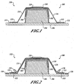
- FIGURE 1 is an end cross-sectional view of a forming system 100 for manufacturing a composite component 102 in accordance with an embodiment of the present invention.
- the forming system 100 includes a lay-up mandrel 104 positioned on a base 106.
- the uncured (or prepreg) composite component 102 is formed on the lay-up mandrel 104, and a release film 108 is positioned over the composite component 102.
- the uncured composite component 102 is formed on a step-shaped portion of the mandrel 104.
- a flexible, elastomeric caul 110 is positioned over the release film 108.
- a pair of strips of a breather material 112 are coupled to the elastomeric caul 110 proximate an outer edge 113 thereof, and are engaged against the base 106.
- the breather material 112 need not be attached to the caul 110, but rather, may simply be positioned between the caul 110 and the base 106.
- the breather material 112 may be placed either above or below the caul 110, or may be eliminated.
- the elastomeric caul 110 is positioned over the composite component 102 such that first and second side portions 114, 116 of the elastomeric caul 110 are spaced apart from the release film 108, the composite component 102, and the lay-up mandrel 104.
- the first and second side portions 114, 116 may be tensioned or stretched between the upper portion of the lay-up mandrel 104 and the base 106, or may be untensioned or unstretched.
- An upper portion 118 of the elastomeric caul 110 is engaged against the release film 108.
- one or more attachment devices may be positioned about the outer edge 113 of the elastomeric caul 110 to secure the elastomeric caul 110 to the base 106 with the first and second side portions 114, 116 bridged between the upper portion 118 and the base 106.
- the elastomeric caul 110 may be formed of a variety of suitable materials.
- the elastomeric caul 110 may be fabricated from silicone rubber, butyl rubber, neoprene, Viton®, or any other suitable elastomeric material.
- the elastomeric caul 110 may be fabricated from silicone rubber manufactured by Rubber Company, Inc. of Fort Worth, Texas, and commercially-available under Product Number EL80 sold by Torr Technology, Inc. of Auburn, Washington.
- the elastomeric caul 110 formed of silicone rubber may be any suitable thickness, including, for example, at least 2.032mm (0.080 inches) thick.
- the elastomeric caul 110 formed from silicone rubber provides a suitable combination of material characteristics, including elongation, durability, and temperature resistance. It will be appreciated, however, that for other composite materials processing applications, other elastomeric materials may be suitable or preferable, and that therefore, the invention should not be viewed as being limited to the particular elastomeric materials described above.
- FIGURE 2 is an end cross-sectional view of the forming system 100 of FIGURE 1 in a second stage of operation 122.
- a bagging film 124 is positioned over the elastomeric caul 110.
- the bagging film 124 extends outwardly beyond the outer edge 113 of the elastomeric caul 110 and is attached to the base 106 by vacuum sealant tape 126.
- the bagging film 124 is fit loosely over the part, with enough excess material to avoid bridging when vacuum is applied and the bagging film 124 is pulled down over the elastomeric caul 110, the composite component 102, and the mandrel 104.
- the bagging film 124 includes one or more pleats 128 of additional bagging material such that the bagging film 124 fits loosely over the elastomeric caul 110.
- FIGURE 3 is an end cross-sectional view of the forming system 100 of FIGURE 1 in a third stage of operation 130 in which a vacuum (or reduced pressure) is formed within the bagging film 124.
- a vacuum or reduced pressure
- FIGURE 3 As shown in FIGURE 3 , as the vacuum is drawn, the pressure underneath the vacuum bagging film 124 is reduced, and the first and second side portions 114, 116 are drawn inwardly toward the composite component 102 (and the lay-up mandrel 104). As the elastomeric caul 110 is drawn inwardly, the elastomeric caul 110 is stretched, and the pleats 128 of the bagging film 124 begin to unfold and expand.
- the pleats 128 are not critical to the operation of the forming system 100, but rather, simply represent one way of providing a suitable quantity of bagging film 124 over the elastomeric caul 110 so that during the evacuation, there is a sufficient quantity of bagging film 124 over the caul 110 to allow the bagging film 124 to come down at all points without bridging.
- FIGURE 4 is an end cross-sectional view of the forming system 100 of FIGURE 1 in a fourth stage of operation 132.
- the elastomeric caul 110 has been drawn tightly into engagement with the release film 108 ( FIGURE 3 ) by the reduced pressure. More specifically, because the outer edge 113 of the elastomeric caul 110 is secured to the base 106, the elastomeric caul 110 is tightly stretched over the lay-up mandrel 104, the composite component 102, and the release film 108. With at least the side portions 114, 116 (and possibly also the upper portion 118) of the elastomeric caul 110 stretched, the elastomeric caul 110 snugly fits over the composite component 102.
- the forming system 100 may be treated or processed to achieve its final, cured condition, such as by placing the forming system 100 into an autoclave or other suitable device and subjecting it to elevated temperature and pressure conditions.
- the composite component 102 may be cured in other ways, including, for example, by exposure to microwave or other suitable wavelength irradiation, by exposure to curing chemicals, agents, or gases, or any other suitable curing means.
- Apparatus and methods in accordance with the present invention may provide significant advantages over the prior art. For example, because the elastomeric caul 110 is stretched tightly as it is pulled down over the lay-up mandrel 104 and the composite component 102 by the reduced pressure, fiber deformation and wrinkling of the composite component 102 are reduced or eliminated. These effects may be particularly observable on the outer or "bagside" surface of the composite component 102, especially in the radii. Thus, the quality of the composite component 102 may be improved, and the costs associated with reworking and repair of the composite component 102 may be greatly reduced.
- embodiments of the present invention may also provide a substantial labor savings and a disposable material savings.
- a hand-tailored surface breather is applied over the part to help evacuate air and prevent nylon bag wrinkles from transferring to the bagside surface of the composite component.
- the breather may be eliminated, saving material cost and labor.
- the invention is not limited to the particular embodiment described above or shown in FIGURES 1-4 , but rather, that a variety of apparatus and methods in accordance with the present invention may be conceived.
- the release film 108 may be eliminated.
- alternate configurations of breather material or other suitable vacuum ports may be conceived to enable the pressure within the elastomeric caul 110 to be reduced.
- the elastomeric caul 110 may be bridged to the base 106 by lesser or greater amounts than the particular embodiment shown in FIGURE 1 , or may even be bridged from a single side of the lay-up mandrel 104 rather than from both sides as shown.
- FIGURE 5 is an isometric view of a forming system 200 in a disengaged position 220 in accordance with an alternate embodiment of the invention.
- FIGURE 6 is an isometric view of the forming system 200 of FIGURE 5 in an engaged position 222.
- an uncured or partially-cured composite component 202 is positioned on an elongated lay-up mandrel 204 having a base 206, and a release film 208 is positioned over the composite component 202 ( FIGURE 5 ).
- An elastomeric caul 210 is positioned over the release film 208.
- the elastomeric caul 210 includes an edge portion 211 having a gas permeable layer 213 disposed therein.
- the gas permeable layer 213 communicates with the surrounding atmosphere through a plurality of breather ports 215 disposed in the elastomeric caul 210.
- a plurality of first attachment members 217 are attached to the edge portion 211 of the elastomeric caul 210, and a corresponding plurality of second attachment members 219 are attached to the base 206.
- first and second attachment members 217, 219 are coupled together (e.g. snapped) such that a first portion 214 ( FIGURE 6 ) of the elastomeric caul 210 is spaced apart from the lay-up mandrel 204, as described more fully above.
- a second portion of the elastomeric caul 210 may (or may not) be similarly bridged between the lay-up mandrel 204 and the base 206 on the other side of the lay-up mandrel 204.
- the vacuum film 218 is positioned over the elastomeric caul 210 and coupled to the base 206 using, for example, vacuum seal tape 126 ( FIGURE 3 ).
- the pressure between the vacuum film 218 and the base 206 (and lay-up mandrel 204) is reduced so that the elastomeric caul 210 is stretched as it is drawn inwardly about the composite component 202 into a snug fitting engagement with the composite component 202.
- the attachment members 217, 219 may be replaced with a variety of other types of attachment members 217, 219, including, for example, hook-and-loop fastening strips (e.g. Velcro ® ), clamping members, or any other suitable attachment devices.
- attachment members may be eliminated.
- the reduced pressure between the elastomeric caul and the base of the lay-up mandrel operates to secure the outer edge of the elastomeric caul in place during the evacuation stage of the process.
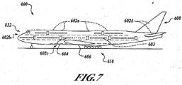
- FIGURE 7 is a side elevational view of an aircraft 600 having one or more composite components 602 formed in accordance with alternate embodiments of the present invention.
- the various components and subsystems of the aircraft 600 may be of known construction and, for the sake of brevity, will not be described in detail herein.
- the aircraft 600 includes one or more propulsion units 604 coupled to a fuselage 605, wing assemblies 606 (or other lifting surfaces), a tail assembly 608, a landing assembly 610, a control system 612 (not visible), and a host of other systems and subsystems that enable proper operation of the aircraft 600.
- propulsion units 604 coupled to a fuselage 605, wing assemblies 606 (or other lifting surfaces), a tail assembly 608, a landing assembly 610, a control system 612 (not visible), and a host of other systems and subsystems that enable proper operation of the aircraft 600.
- apparatus and methods in accordance with the present invention may be utilized in the fabrication of any number of composite components 602 of the aircraft 600, including, for example, the various components and sub-components of the tail assembly 608, the wing assemblies 606, the fuselage 605, and any other suitable portion of the aircraft 600.
- FIGURE 7 is generally representative of a commercial passenger aircraft, including, for example, the 737, 747, 757, 767, 777, and 7E7 models commercially-available from The Boeing Company of Chicago, Illinois
- inventive apparatus and methods disclosed herein may also be employed in the assembly of virtually any other types of aircraft. More specifically, the teachings of the present invention may be applied to the manufacture and assembly of other passenger aircraft, fighter aircraft, cargo aircraft, rotary aircraft, and any other types of manned or unmanned aircraft, including those described, for example, in The Illustrated Encyclopedia of Military Aircraft by Enzo Angelucci, published by Book Sales Publishers, September 2001 , and in Jane's All the World's Aircraft published by Jane's Information Group of Coulsdon, Surrey, United Kingdom .
- apparatus and methods in accordance with the present invention may be utilized in the manufacture of a wide variety composite components for, for example, boats, automobiles, canoes, surfboards, recreational vehicles, or any other suitable vehicle or assembly.
- Embodiments of apparatus and methods in accordance with the present invention may be employed in the fabrication of a multitude of composite components, particularly components have a non-planar or arcuate outer surface. This may include, for example, composite components formed on a lay-up mandrel having any type of non-planar ( i.e. male or female, concave or convex, etc.) surfaces.
- composite components fabricated in accordance with the teachings of the present disclosure may have a "C-channel" cross-sectional shape, which is a particularly common geometric shape for a variety of composite components, including but not limited to those used on aircraft (e.g. ribs or other structural members in empennage, wing, and flooring members of the aircraft).
Claims (17)
- Procédé de fabrication d'un élément composite, le procédé comprenant :l'application d'un matériau composite non durci (102) sur une partie non plane d'un mandrin (104) ;la mise en place d'une plaque élastomère (110) sur le matériau composite non durci (102) de telle sorte que :une première partie (118) de la plaque élastomère (110) soit proche du matériau composite non durci (102) ; etune deuxième partie (114, 116) de la plaque élastomère (110) adjacente à la première partie soit écartée du matériau composite non durci (102) ;le positionnement d'un film d'ensachage (124) sur la plaque élastomère (110) de telle sorte que le matériau composite non durci (102) soit séparé du film d'ensachage (124) par la plaque élastomère (110) et le scellage du film d'ensachage (124) sur une base (106) ; etla création d'un vide à l'intérieur du film d'ensachage (124) de telle sorte que le film d'ensachage (124) et la plaque élastomère (110) soient pressés contre au moins une partie du matériau composite non durci (102).
- Procédé selon la revendication 1, comprenant en outre le durcissement du matériau composite (102).
- Procédé selon la revendication 2, dans lequel le durcissement comprend l'application d'au moins une d'une température élevée et d'une pression élevée.
- Procédé selon la revendication 1, dans lequel l'étape de mise en place comprend au moins l'un d'une tension et d'un étirement d'au moins la deuxième partie de la plaque élastomère (110).
- Procédé selon la revendication 1, comprenant en outre le positionnement d'une couche respirante entre la plaque élastomère (110) et la base (106).
- Procédé selon la revendication 1, dans lequel l'étape de mise en place comprend en outre la mise en place d'une plaque élastomère (110) ayant une partie de bord avec une couche perméable au gaz disposée à l'intérieur.
- Procédé selon la revendication 1, dans lequel l'étape de mise en place comprend en outre la mise en place d'une plaque élastomère (110) ayant une épaisseur d'au moins 2,032 mm (0,08 pouce) .
- Procédé selon la revendication 1, dans lequel l'étape de mise en place comprend en outre la fixation d'une troisième partie de la plaque élastomère (110) dans une position fixe par rapport au mandrin (104) ;
la troisième partie de la plaque (110) étant adjacente à la deuxième partie et opposée à la deuxième partie par rapport à la première partie. - Procédé selon la revendication 8, dans lequel l'étape de fixation comprend en outre la fixation de la plaque élastomère (110) au moyen d'au moins l'une d'une pression, d'une bande Velcro et d'un élément de serrage.
- Procédé selon la revendication 1, dans lequel l'étape de mise en place comprend en outre la mise en place d'une plaque élastomère (110) ayant une troisième partie adjacente à la première partie et écartée du matériau composite (102) ;
comprenant en outre l'étirement de la plaque élastomère (110) de telle sorte que la troisième partie soit amenée à proximité de l'au moins un du matériau composite (102) et du mandrin (104). - Procédé selon la revendication 1, dans lequel l'étape d'application comprend en outre l'application du matériau composite (102) sur un mandrin (104) sous la forme d'un composant d'avion.
- Ensemble pour la fabrication d'un élément composite, l'ensemble comprenant :un mandrin (104) ayant une partie non plane et étant adapté pour recevoir un matériau composite non durci (102) ;une plaque élastomère (110) positionnable au-dessus d'au moins une partie du mandrin (104) lorsqu'un matériau composite non durci (102) est appliqué sur le mandrin (104) de telle sorte que, dans une position initiale :une première partie de la plaque (110) soit proche du matériau composite non durci (102) etune deuxième partie de la plaque adjacente à la première partie est écartée du matériau composite non durci (102) et du mandrin (104) ; etun film d'ensachage (124) positionnable sur la plaque (110) lorsqu'un matériau composite non durci (102) est appliqué sur le mandrin (104) de telle sorte que le matériau composite non durci (102) soit séparé du film d'ensachage (124) par la plaque (110) et lorsque la plaque (110) est positionnée sur le matériau composite non durci (102) et le mandrin (104), et scellable à une base de telle sorte que lorsqu'une pression à l'intérieur du film d'ensachage (124) soit réduite, le film d'ensachage (124) est pressé contre la plaque (110), amenant ainsi la deuxième partie de la plaque (110) à être forcée contre le matériau composite non durci (102).
- Ensemble selon la revendication 12, comprenant en outre une couche respirante positionnable entre la plaque (110) et la base (106).
- Ensemble selon la revendication 13, comprenant en outre un ensemble de fixation adapté pour coupler une troisième partie de la plaque (110) dans une position fixe par rapport au mandrin (104), la troisième partie étant adjacente à la deuxième partie et opposée à la deuxième partie par rapport à la première partie.
- Ensemble selon la revendication 15, dans lequel l'ensemble de fixation comprend au moins l'un d'une pression, d'une bande Velcro et d'un élément de serrage.
- Ensemble selon la revendication 13, comprenant en outre une couche libérable pouvant être disposée entre la plaque (110) et le matériau composite non durci (102).
- Ensemble selon la revendication 13, comprenant en outre un appareil durcissant adapté pour appliquer au moins l'une d'une température élevée et d'une pression élevée au matériau composite non durci.
Applications Claiming Priority (2)
| Application Number | Priority Date | Filing Date | Title |
|---|---|---|---|
| US10/786,885 US7534387B2 (en) | 2004-02-25 | 2004-02-25 | Apparatus and methods for processing composite components using an elastomeric caul |
| PCT/US2005/005229 WO2005082606A1 (fr) | 2004-02-25 | 2005-02-22 | Appareil et procedes de traitement d'elements composites faisant appel a une plaque de presse elastomere |
Publications (2)
| Publication Number | Publication Date |
|---|---|
| EP1732749A1 EP1732749A1 (fr) | 2006-12-20 |
| EP1732749B1 true EP1732749B1 (fr) | 2016-07-20 |
Family
ID=34861868
Family Applications (1)
| Application Number | Title | Priority Date | Filing Date |
|---|---|---|---|
| EP05723291.0A Active EP1732749B1 (fr) | 2004-02-25 | 2005-02-22 | APPAREIL ET PROCEDE DE fabrication D'ELEMENTS COMPOSITES FAISANT APPEL A UNE PLAQUE DE PRESSE ELASTOMERE |
Country Status (6)
| Country | Link |
|---|---|
| US (1) | US7534387B2 (fr) |
| EP (1) | EP1732749B1 (fr) |
| JP (2) | JP2007525345A (fr) |
| CN (1) | CN1946541B (fr) |
| ES (1) | ES2585182T3 (fr) |
| WO (1) | WO2005082606A1 (fr) |
Families Citing this family (48)
| Publication number | Priority date | Publication date | Assignee | Title |
|---|---|---|---|---|
| GB0613872D0 (en) * | 2006-07-12 | 2006-08-23 | Airbus Uk Ltd | Method of manufacturing composite part |
| CN101500774B (zh) * | 2006-09-29 | 2013-10-30 | 东丽株式会社 | 赋型成型模以及使用其的预成型体及纤维增强塑料的制造方法 |
| ES2359090T3 (es) * | 2007-01-22 | 2011-05-18 | Saab Ab | Procedimiento y aparato para la fabricación de un elemento de perfil de larguero de ala. |
| CA2679111C (fr) * | 2007-02-23 | 2013-01-22 | Richard W. Rydin | Procede de fabrication et d'utilisation d'un sac sous vide en caoutchouc naturel forme par pulverisation |
| US7850897B2 (en) * | 2007-03-14 | 2010-12-14 | Spectrum Aeronautical, Llc | Method and device for manufacturing a unitary caul sheet |
| US8672665B2 (en) | 2007-05-18 | 2014-03-18 | Arjr Group, Llc | Vacuum bag with integral fluid transfer conduits and seals for resin transfer and other processes |
| GB0715303D0 (en) * | 2007-08-08 | 2007-09-19 | Airbus Uk Ltd | Composite laminate structure |
| GB0719267D0 (en) * | 2007-10-04 | 2007-11-14 | Airbus Uk Ltd | Method of monitoring the performance of a pressure intensifier |
| GB0719269D0 (en) * | 2007-10-04 | 2007-11-14 | Airbus Uk Ltd | Method of moulding a charge |
| JP5137696B2 (ja) * | 2008-06-04 | 2013-02-06 | 富士重工業株式会社 | 加圧成形パッド |
| GB0813785D0 (en) * | 2008-07-29 | 2008-09-03 | Airbus Uk Ltd | Method of manufacturing a composite element |
| DE102009002697B4 (de) * | 2009-04-28 | 2014-02-27 | Airbus Operations Gmbh | Formkern und Verfahren zur Herstellung eines Faserverbundbauteils für die Luft- und Raumfahrt |
| FI20105115A (fi) | 2010-02-05 | 2011-08-06 | Meteco Oy | Menetelmä komposiittikappaleen valmistamiseksi sekä malli |
| US8192574B1 (en) | 2010-05-13 | 2012-06-05 | Textron Innovations Inc. | Process for bonding a vented hollow component |
| US8585856B1 (en) | 2010-05-13 | 2013-11-19 | Textron Innovations Inc. | Process for fabricating aircraft parts using an integrated form |
| US8182640B1 (en) | 2010-05-13 | 2012-05-22 | Textron Innovations, Inc. | Process for bonding components to a surface |
| US8961732B2 (en) | 2011-01-03 | 2015-02-24 | The Boeing Company | Method and device for compressing a composite radius |
| US8613252B2 (en) * | 2011-02-14 | 2013-12-24 | Sikorsky Aircraft Corporation | Co-curing reusable elastomeric caul plate |
| JP6040547B2 (ja) * | 2011-03-28 | 2016-12-07 | 東レ株式会社 | 繊維強化プラスチックの製造方法 |
| US8556618B2 (en) * | 2011-04-07 | 2013-10-15 | Spirit Aerosystems, Inc. | Method and bladder apparatus for forming composite parts |
| US9051062B1 (en) | 2012-02-08 | 2015-06-09 | Textron Innovations, Inc. | Assembly using skeleton structure |
| US9302455B1 (en) | 2012-02-08 | 2016-04-05 | Textron Innovations, Inc. | Fast cure process |
| US9050757B1 (en) | 2012-02-08 | 2015-06-09 | Textron Innovations, Inc. | System and method for curing composites |
| US9545757B1 (en) | 2012-02-08 | 2017-01-17 | Textron Innovations, Inc. | Composite lay up and method of forming |
| US9649820B1 (en) | 2012-02-08 | 2017-05-16 | Textron Innovations, Inc. | Assembly using skeleton structure |
| US9114586B2 (en) | 2012-02-09 | 2015-08-25 | Sikorsky Aircraft Corporation | Lattice grid caul for honeycomb composite structure |
| US10150233B2 (en) * | 2013-03-19 | 2018-12-11 | The Boeing Company | Method and apparatus for reducing ply wrinkling of composite laminates during forming |
| JP6273804B2 (ja) * | 2013-12-02 | 2018-02-07 | 東レ株式会社 | 繊維強化プラスチック成形体の製造方法 |
| JP6281865B2 (ja) * | 2014-01-31 | 2018-02-21 | 三菱重工業株式会社 | Frp成形治具及びfrp構造体の成形方法 |
| US10399284B2 (en) | 2014-05-16 | 2019-09-03 | The Boeing Company | Method and apparatus for forming contoured composite laminates |
| US9782937B1 (en) | 2014-05-16 | 2017-10-10 | The Boeing Company | Apparatus for forming contoured composite laminates |
| ES2564587B2 (es) * | 2014-09-22 | 2016-12-01 | Aciturri Engineering, S.L.U. | Método de pegado de rigidizadores transversales por cara bolsa en piezas frescas de material compuesto en forma de C |
| US9636876B2 (en) | 2014-10-29 | 2017-05-02 | The Boeing Company | Method, device and apparatus for vacuum forming composite laminates |
| RU2585650C1 (ru) * | 2015-02-04 | 2016-05-27 | Открытое акционерное общество "Пермский завод "Машиностроитель" | Способ изготовления эластичного формующего элемента |
| US9895848B2 (en) | 2015-04-22 | 2018-02-20 | The Boeing Company | Systems and tooling for manufacturing composite parts and related methods |
| US10369756B2 (en) * | 2015-08-25 | 2019-08-06 | The Boeing Company | Method of manufacturing a composite article |
| US10005267B1 (en) | 2015-09-22 | 2018-06-26 | Textron Innovations, Inc. | Formation of complex composite structures using laminate templates |
| US10399283B2 (en) * | 2015-10-06 | 2019-09-03 | The Boeing Company | Method and device for producing contoured composite laminate stiffeners with reduced wrinkling |
| US10611097B2 (en) * | 2016-05-24 | 2020-04-07 | General Electric Company | Methods and systems including pressurized housings for forming materials |
| DE102016209487A1 (de) * | 2016-05-31 | 2017-11-30 | Deutsches Zentrum für Luft- und Raumfahrt e.V. | Induktionsheizvorrichtung, Reparaturverfahren und Vakuumhaubenvorrichtung |
| DE102016115284A1 (de) | 2016-08-17 | 2018-02-22 | Deutsches Zentrum für Luft- und Raumfahrt e.V. | Reparaturverfahren für ein Werkstück aus einem Kunststoffmaterial, Reparaturvorrichtung |
| US10987880B2 (en) * | 2016-09-07 | 2021-04-27 | Mitsubishi Heavy Industries, Ltd. | Method for molding composite material and jig for molding composite material |
| GB2556043A (en) * | 2016-11-11 | 2018-05-23 | Composite Tech And Applications Limited | A method of de-bulking a pre-form for a composite component |
| US10391684B1 (en) | 2016-11-30 | 2019-08-27 | Spintech, LLC | Cauls and methods of using cauls to produce composite articles |
| WO2019023665A1 (fr) * | 2017-07-28 | 2019-01-31 | Airtech International, Inc. | Fixation élastique pour plis de sac sous vide |
| US11155047B2 (en) * | 2018-10-08 | 2021-10-26 | Textron Innovations Inc. | Caul body and a method for forming a composite structure |
| CN110884762A (zh) * | 2019-10-21 | 2020-03-17 | 成都鲁晨新材料科技有限公司 | 一种可重复使用的真空袋 |
| JP7225320B2 (ja) * | 2021-06-28 | 2023-02-20 | 三菱重工業株式会社 | 賦形方法および賦形装置 |
Family Cites Families (33)
| Publication number | Priority date | Publication date | Assignee | Title |
|---|---|---|---|---|
| US3334383A (en) * | 1965-11-03 | 1967-08-08 | Lockheed Aircraft Corp | Molding apparatus |
| US3703422A (en) * | 1970-01-02 | 1972-11-21 | North American Rockwell | Polyaromatic resin faced honeycomb panel and method for making same |
| US4622091A (en) * | 1984-11-29 | 1986-11-11 | The Boeing Company | Resin film infusion process and apparatus |
| GB8507312D0 (en) * | 1985-03-21 | 1985-05-01 | Ici Plc | Producing shaped articles |
| JPS61283514A (ja) * | 1985-06-10 | 1986-12-13 | Mitsubishi Electric Corp | 繊維強化プラスチツクの製造方法 |
| US5123985A (en) * | 1986-09-02 | 1992-06-23 | Patricia Evans | Vacuum bagging apparatus and method including a thermoplastic elastomer film vacuum bag |
| US4834929A (en) * | 1987-03-03 | 1989-05-30 | 3D Manufacturing, Inc. | Method of making molds |
| US4915896A (en) * | 1987-09-01 | 1990-04-10 | Phillips Petroleum Company | Vacuum bagging process for fiber reinforced thermoplastics |
| US4853172A (en) * | 1987-12-01 | 1989-08-01 | United Technologies Corporation | Method of fabricating tubular composite structures |
| US4904436A (en) * | 1988-01-29 | 1990-02-27 | Phillips Petroleum Company | Consolidation of thermoplastic panels |
| US4926356A (en) * | 1988-02-29 | 1990-05-15 | The Boeing Company | Test apparatus for measuring heat release of certain materials |
| JPH01259912A (ja) * | 1988-04-11 | 1989-10-17 | Fuji Heavy Ind Ltd | 熱硬化樹脂系複合材の成形方法 |
| US4913639A (en) * | 1988-09-13 | 1990-04-03 | Wheeler Robert G | Composite caul plate |
| US5023042A (en) * | 1989-06-29 | 1991-06-11 | Gary Efferding | Flexible mold for making seamless sailboards |
| JP3004309B2 (ja) * | 1990-04-09 | 2000-01-31 | 富士重工業株式会社 | 繊維強化樹脂積層体の製造方法 |
| US5152949A (en) * | 1990-12-19 | 1992-10-06 | United Technologies Corporation | Tooling method for resin transfer molding |
| CA2056330C (fr) * | 1990-12-19 | 2003-06-10 | Alexander C. Dublinski | Methode servant a fabriquer une piece complexe faite de materiau composite |
| US5292475A (en) * | 1992-03-06 | 1994-03-08 | Northrop Corporation | Tooling and process for variability reduction of composite structures |
| US5648109A (en) * | 1995-05-03 | 1997-07-15 | Massachusetts Institute Of Technology | Apparatus for diaphragm forming |
| US5807593A (en) * | 1996-07-10 | 1998-09-15 | The Boeing Company | Vacuum bag not requiring disposable breathers |
| US5817269A (en) * | 1996-10-25 | 1998-10-06 | The Boeing Company | Composite fabrication method and tooling to improve part consolidation |
| US6217000B1 (en) * | 1996-10-25 | 2001-04-17 | The Boeing Company | Composite fabrication method and tooling to improve part consolidation |
| JPH10146898A (ja) * | 1996-11-15 | 1998-06-02 | Honda Motor Co Ltd | 繊維強化複合材の成形方法 |
| JP3815848B2 (ja) * | 1997-04-25 | 2006-08-30 | 富士重工業株式会社 | 複合材の成形装置および成形方法 |
| US5902535A (en) * | 1997-07-30 | 1999-05-11 | Mcdonnell Douglas Corporation | Resin film infusion mold tooling and molding method |
| US6290895B1 (en) * | 1997-10-14 | 2001-09-18 | General Electric Company | Selectively flexible caul and method of use |
| US6245275B1 (en) * | 1999-05-13 | 2001-06-12 | Vought Aircraft Industries, Inc. | Method for fabricating composite structures |
| JP2001038752A (ja) * | 1999-07-30 | 2001-02-13 | Fuji Heavy Ind Ltd | 複合材曲面パネルの成形装置及び成形方法 |
| ES2234707T5 (es) * | 1999-12-07 | 2008-06-16 | The Boeing Company | Procedimiento de infusion al vacio, con doble bolsa, para fabricar un material compuesto y material compuesto asi obtenido. |
| US6620369B1 (en) * | 2000-02-09 | 2003-09-16 | Northrop Grumman Corporation | Net molding of resin composite parts |
| ES2184551B1 (es) * | 2000-03-07 | 2004-09-01 | Airbus España S.L. | Procedimiento de fabricacion de estructuras primarias en material compuesto con curado en util hembra. |
| GB0014113D0 (en) | 2000-06-10 | 2000-08-02 | Gkn Westland Helicopters Ltd | Improvements in or relating to moulding |
| US7029267B2 (en) * | 2003-10-23 | 2006-04-18 | Saint- Gobain Technical Fabrics Canada, Ltd | Reusable vacuum bag and methods of its use |
-
2004
- 2004-02-25 US US10/786,885 patent/US7534387B2/en active Active
-
2005
- 2005-02-22 CN CN2005800129825A patent/CN1946541B/zh active Active
- 2005-02-22 EP EP05723291.0A patent/EP1732749B1/fr active Active
- 2005-02-22 ES ES05723291.0T patent/ES2585182T3/es active Active
- 2005-02-22 WO PCT/US2005/005229 patent/WO2005082606A1/fr active Application Filing
- 2005-02-22 JP JP2007500890A patent/JP2007525345A/ja active Pending
-
2012
- 2012-03-22 JP JP2012065607A patent/JP5615864B2/ja active Active
Also Published As
| Publication number | Publication date |
|---|---|
| CN1946541A (zh) | 2007-04-11 |
| US7534387B2 (en) | 2009-05-19 |
| JP2007525345A (ja) | 2007-09-06 |
| JP2012187925A (ja) | 2012-10-04 |
| JP5615864B2 (ja) | 2014-10-29 |
| US20050183818A1 (en) | 2005-08-25 |
| ES2585182T3 (es) | 2016-10-04 |
| EP1732749A1 (fr) | 2006-12-20 |
| CN1946541B (zh) | 2011-03-02 |
| WO2005082606A1 (fr) | 2005-09-09 |
Similar Documents
| Publication | Publication Date | Title |
|---|---|---|
| EP1732749B1 (fr) | APPAREIL ET PROCEDE DE fabrication D'ELEMENTS COMPOSITES FAISANT APPEL A UNE PLAQUE DE PRESSE ELASTOMERE | |
| US9937672B2 (en) | Cure tool with integrated edge breather and method of making the same | |
| US11155069B2 (en) | Method and system of forming a composite laminate | |
| EP3409580A1 (fr) | Longeron à angle aigu en matière composite pour profil aérodynamique et procédé de fabrication | |
| US9586344B2 (en) | Method and system of forming a releasable support and method of pre-cure removal of a composite laminate | |
| US11904560B2 (en) | Vacuum bag-less composite repair systems and methods | |
| US8857764B2 (en) | Fly away caul plate | |
| US9914549B2 (en) | Method, system and apparatus for assembling a composite wing skin with stiffeners | |
| US20190210308A1 (en) | Method for repairing a composite stringer with a composite repair cap | |
| JP7355529B2 (ja) | 複合構造を形成するための可撓性マンドレル | |
| EP4197719A1 (fr) | Appareil de préhension et systèmes et procédés associés pour saisir des matériaux souples | |
| EP4074497A1 (fr) | Plaques de presse ayant des joints de bord intégrés et procédé d'étanchéification |
Legal Events
| Date | Code | Title | Description |
|---|---|---|---|
| PUAI | Public reference made under article 153(3) epc to a published international application that has entered the european phase |
Free format text: ORIGINAL CODE: 0009012 |
|
| 17P | Request for examination filed |
Effective date: 20060925 |
|
| AK | Designated contracting states |
Kind code of ref document: A1 Designated state(s): AT BE BG CH CY CZ DE DK EE ES FI FR GB GR HU IE IS IT LI LT LU MC NL PL PT RO SE SI SK TR |
|
| DAX | Request for extension of the european patent (deleted) | ||
| 17Q | First examination report despatched |
Effective date: 20071001 |
|
| GRAP | Despatch of communication of intention to grant a patent |
Free format text: ORIGINAL CODE: EPIDOSNIGR1 |
|
| INTG | Intention to grant announced |
Effective date: 20151002 |
|
| INTG | Intention to grant announced |
Effective date: 20160212 |
|
| GRAS | Grant fee paid |
Free format text: ORIGINAL CODE: EPIDOSNIGR3 |
|
| GRAA | (expected) grant |
Free format text: ORIGINAL CODE: 0009210 |
|
| AK | Designated contracting states |
Kind code of ref document: B1 Designated state(s): AT BE BG CH CY CZ DE DK EE ES FI FR GB GR HU IE IS IT LI LT LU MC NL PL PT RO SE SI SK TR |
|
| REG | Reference to a national code |
Ref country code: GB Ref legal event code: FG4D |
|
| REG | Reference to a national code |
Ref country code: CH Ref legal event code: EP |
|
| REG | Reference to a national code |
Ref country code: IE Ref legal event code: FG4D |
|
| REG | Reference to a national code |
Ref country code: AT Ref legal event code: REF Ref document number: 813684 Country of ref document: AT Kind code of ref document: T Effective date: 20160815 |
|
| REG | Reference to a national code |
Ref country code: DE Ref legal event code: R096 Ref document number: 602005049768 Country of ref document: DE |
|
| REG | Reference to a national code |
Ref country code: ES Ref legal event code: FG2A Ref document number: 2585182 Country of ref document: ES Kind code of ref document: T3 Effective date: 20161004 |
|
| REG | Reference to a national code |
Ref country code: LT Ref legal event code: MG4D |
|
| REG | Reference to a national code |
Ref country code: NL Ref legal event code: MP Effective date: 20160720 |
|
| REG | Reference to a national code |
Ref country code: AT Ref legal event code: MK05 Ref document number: 813684 Country of ref document: AT Kind code of ref document: T Effective date: 20160720 |
|
| PG25 | Lapsed in a contracting state [announced via postgrant information from national office to epo] |
Ref country code: LT Free format text: LAPSE BECAUSE OF FAILURE TO SUBMIT A TRANSLATION OF THE DESCRIPTION OR TO PAY THE FEE WITHIN THE PRESCRIBED TIME-LIMIT Effective date: 20160720 Ref country code: NL Free format text: LAPSE BECAUSE OF FAILURE TO SUBMIT A TRANSLATION OF THE DESCRIPTION OR TO PAY THE FEE WITHIN THE PRESCRIBED TIME-LIMIT Effective date: 20160720 Ref country code: FI Free format text: LAPSE BECAUSE OF FAILURE TO SUBMIT A TRANSLATION OF THE DESCRIPTION OR TO PAY THE FEE WITHIN THE PRESCRIBED TIME-LIMIT Effective date: 20160720 Ref country code: IS Free format text: LAPSE BECAUSE OF FAILURE TO SUBMIT A TRANSLATION OF THE DESCRIPTION OR TO PAY THE FEE WITHIN THE PRESCRIBED TIME-LIMIT Effective date: 20161120 |
|
| REG | Reference to a national code |
Ref country code: FR Ref legal event code: PLFP Year of fee payment: 13 |
|
| PG25 | Lapsed in a contracting state [announced via postgrant information from national office to epo] |
Ref country code: SE Free format text: LAPSE BECAUSE OF FAILURE TO SUBMIT A TRANSLATION OF THE DESCRIPTION OR TO PAY THE FEE WITHIN THE PRESCRIBED TIME-LIMIT Effective date: 20160720 Ref country code: BE Free format text: LAPSE BECAUSE OF FAILURE TO SUBMIT A TRANSLATION OF THE DESCRIPTION OR TO PAY THE FEE WITHIN THE PRESCRIBED TIME-LIMIT Effective date: 20160720 Ref country code: PT Free format text: LAPSE BECAUSE OF FAILURE TO SUBMIT A TRANSLATION OF THE DESCRIPTION OR TO PAY THE FEE WITHIN THE PRESCRIBED TIME-LIMIT Effective date: 20161121 Ref country code: AT Free format text: LAPSE BECAUSE OF FAILURE TO SUBMIT A TRANSLATION OF THE DESCRIPTION OR TO PAY THE FEE WITHIN THE PRESCRIBED TIME-LIMIT Effective date: 20160720 Ref country code: PL Free format text: LAPSE BECAUSE OF FAILURE TO SUBMIT A TRANSLATION OF THE DESCRIPTION OR TO PAY THE FEE WITHIN THE PRESCRIBED TIME-LIMIT Effective date: 20160720 Ref country code: GR Free format text: LAPSE BECAUSE OF FAILURE TO SUBMIT A TRANSLATION OF THE DESCRIPTION OR TO PAY THE FEE WITHIN THE PRESCRIBED TIME-LIMIT Effective date: 20161021 |
|
| REG | Reference to a national code |
Ref country code: DE Ref legal event code: R097 Ref document number: 602005049768 Country of ref document: DE |
|
| PG25 | Lapsed in a contracting state [announced via postgrant information from national office to epo] |
Ref country code: RO Free format text: LAPSE BECAUSE OF FAILURE TO SUBMIT A TRANSLATION OF THE DESCRIPTION OR TO PAY THE FEE WITHIN THE PRESCRIBED TIME-LIMIT Effective date: 20160720 Ref country code: EE Free format text: LAPSE BECAUSE OF FAILURE TO SUBMIT A TRANSLATION OF THE DESCRIPTION OR TO PAY THE FEE WITHIN THE PRESCRIBED TIME-LIMIT Effective date: 20160720 |
|
| PLBE | No opposition filed within time limit |
Free format text: ORIGINAL CODE: 0009261 |
|
| STAA | Information on the status of an ep patent application or granted ep patent |
Free format text: STATUS: NO OPPOSITION FILED WITHIN TIME LIMIT |
|
| PG25 | Lapsed in a contracting state [announced via postgrant information from national office to epo] |
Ref country code: SK Free format text: LAPSE BECAUSE OF FAILURE TO SUBMIT A TRANSLATION OF THE DESCRIPTION OR TO PAY THE FEE WITHIN THE PRESCRIBED TIME-LIMIT Effective date: 20160720 Ref country code: DK Free format text: LAPSE BECAUSE OF FAILURE TO SUBMIT A TRANSLATION OF THE DESCRIPTION OR TO PAY THE FEE WITHIN THE PRESCRIBED TIME-LIMIT Effective date: 20160720 Ref country code: CZ Free format text: LAPSE BECAUSE OF FAILURE TO SUBMIT A TRANSLATION OF THE DESCRIPTION OR TO PAY THE FEE WITHIN THE PRESCRIBED TIME-LIMIT Effective date: 20160720 Ref country code: BG Free format text: LAPSE BECAUSE OF FAILURE TO SUBMIT A TRANSLATION OF THE DESCRIPTION OR TO PAY THE FEE WITHIN THE PRESCRIBED TIME-LIMIT Effective date: 20161020 |
|
| 26N | No opposition filed |
Effective date: 20170421 |
|
| PG25 | Lapsed in a contracting state [announced via postgrant information from national office to epo] |
Ref country code: SI Free format text: LAPSE BECAUSE OF FAILURE TO SUBMIT A TRANSLATION OF THE DESCRIPTION OR TO PAY THE FEE WITHIN THE PRESCRIBED TIME-LIMIT Effective date: 20160720 |
|
| PG25 | Lapsed in a contracting state [announced via postgrant information from national office to epo] |
Ref country code: MC Free format text: LAPSE BECAUSE OF FAILURE TO SUBMIT A TRANSLATION OF THE DESCRIPTION OR TO PAY THE FEE WITHIN THE PRESCRIBED TIME-LIMIT Effective date: 20160720 |
|
| REG | Reference to a national code |
Ref country code: CH Ref legal event code: PL |
|
| PG25 | Lapsed in a contracting state [announced via postgrant information from national office to epo] |
Ref country code: CH Free format text: LAPSE BECAUSE OF NON-PAYMENT OF DUE FEES Effective date: 20170228 Ref country code: LI Free format text: LAPSE BECAUSE OF NON-PAYMENT OF DUE FEES Effective date: 20170228 |
|
| REG | Reference to a national code |
Ref country code: IE Ref legal event code: MM4A |
|
| PG25 | Lapsed in a contracting state [announced via postgrant information from national office to epo] |
Ref country code: LU Free format text: LAPSE BECAUSE OF NON-PAYMENT OF DUE FEES Effective date: 20170222 |
|
| REG | Reference to a national code |
Ref country code: FR Ref legal event code: PLFP Year of fee payment: 14 |
|
| PG25 | Lapsed in a contracting state [announced via postgrant information from national office to epo] |
Ref country code: IE Free format text: LAPSE BECAUSE OF NON-PAYMENT OF DUE FEES Effective date: 20170222 |
|
| PG25 | Lapsed in a contracting state [announced via postgrant information from national office to epo] |
Ref country code: HU Free format text: LAPSE BECAUSE OF FAILURE TO SUBMIT A TRANSLATION OF THE DESCRIPTION OR TO PAY THE FEE WITHIN THE PRESCRIBED TIME-LIMIT; INVALID AB INITIO Effective date: 20050222 |
|
| PG25 | Lapsed in a contracting state [announced via postgrant information from national office to epo] |
Ref country code: CY Free format text: LAPSE BECAUSE OF NON-PAYMENT OF DUE FEES Effective date: 20160720 |
|
| REG | Reference to a national code |
Ref country code: DE Ref legal event code: R082 Ref document number: 602005049768 Country of ref document: DE Representative=s name: MAIER, LL.M., MICHAEL C., DE Ref country code: DE Ref legal event code: R082 Ref document number: 602005049768 Country of ref document: DE Representative=s name: BOULT WADE TENNANT LLP, DE |
|
| REG | Reference to a national code |
Ref country code: DE Ref legal event code: R082 Ref document number: 602005049768 Country of ref document: DE Representative=s name: BOULT WADE TENNANT LLP, DE |
|
| PG25 | Lapsed in a contracting state [announced via postgrant information from national office to epo] |
Ref country code: TR Free format text: LAPSE BECAUSE OF FAILURE TO SUBMIT A TRANSLATION OF THE DESCRIPTION OR TO PAY THE FEE WITHIN THE PRESCRIBED TIME-LIMIT Effective date: 20160720 |
|
| PGFP | Annual fee paid to national office [announced via postgrant information from national office to epo] |
Ref country code: FR Payment date: 20230223 Year of fee payment: 19 Ref country code: ES Payment date: 20230301 Year of fee payment: 19 |
|
| PGFP | Annual fee paid to national office [announced via postgrant information from national office to epo] |
Ref country code: IT Payment date: 20230221 Year of fee payment: 19 |
|
| P01 | Opt-out of the competence of the unified patent court (upc) registered |
Effective date: 20230503 |
|
| PGFP | Annual fee paid to national office [announced via postgrant information from national office to epo] |
Ref country code: ES Payment date: 20240301 Year of fee payment: 20 |
|
| PGFP | Annual fee paid to national office [announced via postgrant information from national office to epo] |
Ref country code: DE Payment date: 20240228 Year of fee payment: 20 Ref country code: GB Payment date: 20240227 Year of fee payment: 20 |