EP1731455B1 - Detektion und Vorrichtung zur Detektion von Aufzeichnungsträgern - Google Patents
Detektion und Vorrichtung zur Detektion von Aufzeichnungsträgern Download PDFInfo
- Publication number
- EP1731455B1 EP1731455B1 EP06011005A EP06011005A EP1731455B1 EP 1731455 B1 EP1731455 B1 EP 1731455B1 EP 06011005 A EP06011005 A EP 06011005A EP 06011005 A EP06011005 A EP 06011005A EP 1731455 B1 EP1731455 B1 EP 1731455B1
- Authority
- EP
- European Patent Office
- Prior art keywords
- receiver
- transmitter
- characteristic
- recording media
- transducer
- Prior art date
- Legal status (The legal status is an assumption and is not a legal conclusion. Google has not performed a legal analysis and makes no representation as to the accuracy of the status listed.)
- Active
Links
Images




Classifications
-
- B—PERFORMING OPERATIONS; TRANSPORTING
- B65—CONVEYING; PACKING; STORING; HANDLING THIN OR FILAMENTARY MATERIAL
- B65H—HANDLING THIN OR FILAMENTARY MATERIAL, e.g. SHEETS, WEBS, CABLES
- B65H7/00—Controlling article feeding, separating, pile-advancing, or associated apparatus, to take account of incorrect feeding, absence of articles, or presence of faulty articles
- B65H7/02—Controlling article feeding, separating, pile-advancing, or associated apparatus, to take account of incorrect feeding, absence of articles, or presence of faulty articles by feelers or detectors
- B65H7/04—Controlling article feeding, separating, pile-advancing, or associated apparatus, to take account of incorrect feeding, absence of articles, or presence of faulty articles by feelers or detectors responsive to absence of articles, e.g. exhaustion of pile
-
- B—PERFORMING OPERATIONS; TRANSPORTING
- B65—CONVEYING; PACKING; STORING; HANDLING THIN OR FILAMENTARY MATERIAL
- B65H—HANDLING THIN OR FILAMENTARY MATERIAL, e.g. SHEETS, WEBS, CABLES
- B65H7/00—Controlling article feeding, separating, pile-advancing, or associated apparatus, to take account of incorrect feeding, absence of articles, or presence of faulty articles
- B65H7/02—Controlling article feeding, separating, pile-advancing, or associated apparatus, to take account of incorrect feeding, absence of articles, or presence of faulty articles by feelers or detectors
- B65H7/06—Controlling article feeding, separating, pile-advancing, or associated apparatus, to take account of incorrect feeding, absence of articles, or presence of faulty articles by feelers or detectors responsive to presence of faulty articles or incorrect separation or feed
- B65H7/12—Controlling article feeding, separating, pile-advancing, or associated apparatus, to take account of incorrect feeding, absence of articles, or presence of faulty articles by feelers or detectors responsive to presence of faulty articles or incorrect separation or feed responsive to double feed or separation
- B65H7/125—Controlling article feeding, separating, pile-advancing, or associated apparatus, to take account of incorrect feeding, absence of articles, or presence of faulty articles by feelers or detectors responsive to presence of faulty articles or incorrect separation or feed responsive to double feed or separation sensing the double feed or separation without contacting the articles
-
- B—PERFORMING OPERATIONS; TRANSPORTING
- B65—CONVEYING; PACKING; STORING; HANDLING THIN OR FILAMENTARY MATERIAL
- B65H—HANDLING THIN OR FILAMENTARY MATERIAL, e.g. SHEETS, WEBS, CABLES
- B65H2553/00—Sensing or detecting means
- B65H2553/20—Sensing or detecting means using electric elements
- B65H2553/22—Magnetic detectors, e.g. Hall detectors
-
- B—PERFORMING OPERATIONS; TRANSPORTING
- B65—CONVEYING; PACKING; STORING; HANDLING THIN OR FILAMENTARY MATERIAL
- B65H—HANDLING THIN OR FILAMENTARY MATERIAL, e.g. SHEETS, WEBS, CABLES
- B65H2553/00—Sensing or detecting means
- B65H2553/20—Sensing or detecting means using electric elements
- B65H2553/23—Capacitive detectors, e.g. electrode arrangements
-
- B—PERFORMING OPERATIONS; TRANSPORTING
- B65—CONVEYING; PACKING; STORING; HANDLING THIN OR FILAMENTARY MATERIAL
- B65H—HANDLING THIN OR FILAMENTARY MATERIAL, e.g. SHEETS, WEBS, CABLES
- B65H2553/00—Sensing or detecting means
- B65H2553/30—Sensing or detecting means using acoustic or ultrasonic elements
-
- B—PERFORMING OPERATIONS; TRANSPORTING
- B65—CONVEYING; PACKING; STORING; HANDLING THIN OR FILAMENTARY MATERIAL
- B65H—HANDLING THIN OR FILAMENTARY MATERIAL, e.g. SHEETS, WEBS, CABLES
- B65H2553/00—Sensing or detecting means
- B65H2553/40—Sensing or detecting means using optical, e.g. photographic, elements
- B65H2553/41—Photoelectric detectors
- B65H2553/412—Photoelectric detectors in barrier arrangements, i.e. emitter facing a receptor element
-
- B—PERFORMING OPERATIONS; TRANSPORTING
- B65—CONVEYING; PACKING; STORING; HANDLING THIN OR FILAMENTARY MATERIAL
- B65H—HANDLING THIN OR FILAMENTARY MATERIAL, e.g. SHEETS, WEBS, CABLES
- B65H2557/00—Means for control not provided for in groups B65H2551/00 - B65H2555/00
- B65H2557/20—Calculating means; Controlling methods
- B65H2557/24—Calculating methods; Mathematic models
- B65H2557/242—Calculating methods; Mathematic models involving a particular data profile or curve
-
- B—PERFORMING OPERATIONS; TRANSPORTING
- B65—CONVEYING; PACKING; STORING; HANDLING THIN OR FILAMENTARY MATERIAL
- B65H—HANDLING THIN OR FILAMENTARY MATERIAL, e.g. SHEETS, WEBS, CABLES
- B65H2701/00—Handled material; Storage means
- B65H2701/10—Handled articles or webs
- B65H2701/19—Specific article or web
- B65H2701/1912—Banknotes, bills and cheques or the like
Definitions
- the invention relates to a method according to the preamble of claim 1 and a device according to the preamble of claim 12 for the contactless detection of layered, flat objects, in particular of sheet or sheet-shaped recording media.
- sheet-shaped or sheet-shaped recording medium is understood very broadly in this application. On the one hand, these are understood to mean papers which are used in office equipment such as scanners, printing units, copiers, but also in cash singlers and printing presses. On the other hand, the term of the recording medium should also include the area of the adhesively bonded, layered materials, in particular in the sense of labels, adhesive, tearing or tear points. Films and banknotes are subsumed in this sense under record.
- the known device makes way for using two sensor devices each with two transducers.
- ultrasound both an amplitude evaluation and a phase evaluation are performed.
- the influencing disturbances or the drift of the ultrasonic frequency are consciously detected by the use of a second ultrasonic comparison measuring section and formed in a comparison circuit with the corresponding measured values to form differential values, which are taken into account in the detection statement.
- Different paper weights require a teach-in step.
- the known device and the method in this way already disturbances such as conversion, temperature drift, runtime changes due to ambient temperature into account.
- the detectable grammage weights are in a relatively narrow range of, for example, 35 to 400 g / m 2 .
- this known device and the method is technically very complex to look at, without a relatively high flexibility in terms of a wide range of grammages would be achieved.
- the object of the invention is therefore to improve a method and a device of the generic type so that, taking into account an economical, technical realization best possible security in terms of the detection of multiple sheets or single sheet or the separation of record carriers or various flat objects can be achieved , although this should be possible over a wide range of basis weights or over a wide range of different flat objects.
- An essential core idea of the invention is therefore to separate the sensor device or sensor devices used, eg according to the sound principle, in particular the ultrasound principle, with transmitter and receiver in such a way that there is a complete galvanic separation from the receiver side on the transmitter side and in addition the transmitter and receiver are completely mechanically separated from one another be decoupled.
- transmitter and receiver adjacent to the detection gap in which usually the recording medium between transmitter and receiver are passed, arranged electrically completely separated from each other and placed on separate modules. This means that even the supply of transmitter and receiver can be carried out separately, in particular, for example, via two separate power supply units.
- a teach-in process on a recording medium or on an isolated planar object can be provided in combination with the method of the correction characteristic in the device in order to expand the material spectrum to be detected.
- the increase in the sensitivity of the receiver can be achieved, for example, by a greater gain in the input signal amplifier of the receiver.
- the sensor device used according to the invention can in principle be of various types of sensory action and function in an optical, electromagnetic, inductive, capacitive manner or take into account a combination of these active principles.
- the decisive factor is the distinction between transmitter and receiver, in which at least one galvanic signal separation takes place, even when supplied from a common power supply.
- the ultrasonic based sensor device is cited as a preferred example.
- Another important idea of the invention here is that already a sensor device with a respective converter as Transmitter and receiver is sufficient to ensure the high detection reliability and reliability, ie it can be dispensed, for example, reference measuring distances. It is therefore sufficient for a unidirectional measuring section with only one pair of transducers between which the corresponding recording medium are guided relative to the detection of multiple sheets, missing sheets or individual sheets. The noise level in the receiver can therefore be significantly reduced by the measures mentioned above. It is therefore achieved a high level of efficiency, without the need for complex and expensivearrimessglazedn or other compensation methods.
- a plurality of such sensor devices can be connected in parallel without and with correspondingly conventional synchronization of the individual sensors, in order, e.g. to achieve a quality control of the material to be measured with a very wide material to be measured.
- This method can e.g. in the case of wide laminated paper webs, to detect voids or delamination on the paper web or any other sheet or material, for example to ensure the product quality of these materials.
- converter is understood in this application and with regard to an ultrasonic sensor to the effect that a working according to the respective physical principle transducer element is present, which forms the common electromechanical assembly "converter" with the required mechanical fixing elements.
- a stimulating or receiving piezo layer is present and optionally a corresponding metal ring for improving the transducer properties.
- a decoupling layer is then provided which measures the characteristic impedance of the piezoelectric ceramic to the characteristic impedance the air as best as possible.
- Transducer element and Auskoppeltik be included in a transducer recording, which is foamed, the latter measure also serves to damp the converter.
- a converter screen cup is provided to the outside, which in turn acts as a mechanical receptacle, ie housing for the transmitter or receiver, with the outer transducer receptacle.
- transducer elements e.g. Phototransistor and photodiode or other such similar electromagnetic radiation transmitter and receiver can be used.
- the measures according to the invention therefore make it possible to dispense with interference-prone cable connections between transmitter and receiver.
- service work can be carried out more easily, since damage to connecting lines between transmitter and receiver can not occur at all.
- the transmission signal is subjected to at least one frequency modulation. This prevents standing between the record carrier and the receiver waves in the transmission operation can occur.
- the frequency modulation can also be used to compensate for aging effects of the converter, so that the amplitude maximum used should always lie in the swept frequency range.
- Another advantage of the frequency modulation in the invention is that transducer tolerances of the sensor elements can be corrected automatically during operation by the frequency modulation. Since the pairs of transducers usually have different resonance frequencies, is by a frequency sweep f s the Resonance maximum exceeded periodically. If the response time of the device is significantly less than 1 / f s , the property of each individual transducer or transducer pair can be used optimally for sound transmission in this way.
- the sensor device has also proven to be advantageous for the sensor device to be switchable from pulsed operation to continuous operation at the transmitter, with continuous operation for avoiding standing waves, phase jumps and / or short pauses of the transmit signal, or modulation of the transmit signal described above is used.
- the receiver can be synchronized to the transmitter.
- the synchronization of the receiver to the transmitter here, to name just one example, done in a kind of clock recovery, eg by triggering a PLL circuit or by means of a synchronization pulse. It is also possible to automatically correct transducer tolerances of ultrasonic sensors before and / or during operation. On the one hand, a normalization of the transducer pairs to a fixed value at a predetermined fixed distance, for example, the optimum mounting distance, is required for this purpose. This results in a correction factor, which is then stored in the evaluating software as a table and then comes when the device is used.
- the invention also offers the advantage that the distance between transmitter and receiver with the high detection reliability is not limited to a fixed distance, but can be kept variable according to the requirements and applications. This is especially true for the use of sound, in particular ultrasound and for electromagnetic sensors, in particular optical sensors, in which the transducer properties change over the lifetime.
- the transducers can be configured as straight or angled transducers, the transducers are introduced with the transducer holder in the housing, in particular a cylindrical or cuboid housing, or have no device housing.
- the transducers can be applied directly, in particular evenly parallel, or at a right angle to or on the carrier, which is usually a circuit board or circuit board.
- the carrier which is usually a circuit board or circuit board.
- Transmitter and receiver can therefore be combined with each other as a pair of transducers in different ways and with different housings, it is essential here that the axial alignment of the radiation between transmitter and receiver is given.
- the sensor devices thus formed, which from a separate transmitter and Consist of receivers can thus have a housing which completely, in particular sealingly encases the central assemblies transducer or transducer holder and PCB holder or have no housing.
- These sensor devices can in turn be used in devices such as office machines, sheet-like recording medium processing and processing machines such as printing units, copiers, cash dispensers, voting machines or the like.
- the converter mounted solely on a carrier can be installed in the machines processing sheet materials, these machine housings ensuring the protection of the sensor applied to a carrier.
- the inventive method represents an economically efficient method to incorporate sensors without significant technical disadvantages in the recording medium processing machines.
- Fig. 1 schematically the basic idea of the invention is shown.
- the transmitter T is electronically and mechanically completely separated from the receiver R, on the one hand a galvanic isolation between transmitter T and receiver R, and on the other hand a complete mechanical separation is provided on different modules.
- the transmitter T is in this case on a separate module 12, usually a separated circuit board, which at least by the width of the guide gap 16 for the flat objects, recording medium or Messguts 18 of the assembly 14, which also in a preferred manner separated circuit board is performed, or the receiver R is spaced.
- the signal emitted by the transmitter T is transmitted through the existing record carrier (s) and received in the receiver R as the measurement signal UM.
- this measurement signal is supplied to a signal amplifier 4 with, for example, n signal paths and subjected to a rating with corresponding correction characteristic curves.
- the schematic measured characteristic curve UM shown above the signal amplifier 4 shows at least one logarithmically or exponentially or the like sloping curve over the abscissa provided on the grammage range or the attenuation of the transmission signal accompanying the sample or recording medium.
- the correction characteristics fed or supplied to the signal amplifier 4 are so embossed that in the case of the detection of single arcs, ie the presence or separation of a single recording medium, they produce ideally a target characteristic U Z at the output, which is shown schematically and ideally results in a constant trace without slope. That is, ideally, the voltage swing delta U Z goes to zero, so that over the entire grammage range or the entire material spectrum on recording media, a maximum voltage difference with respect to a missing sheet or air or a double sheet is achieved or for any thickness separated recording medium always gives the same signal level.
- the real circuit provides an approximately linearly decreasing target characteristic U Z over the grammage or the correlated signal attenuation of the flat singulated material or recording medium.
- This largely ideal target characteristic U Z is subsequently a microprocessor ⁇ P for further evaluation and subsequent Display whether an isolated record carrier or a double / multiple sheet or missing sheet is present, forwarded.
- any other sensor device on an optical, electromagnetic, capacitive or inductive basis or the like may be used or combined with one another instead of the aforementioned ultrasound sensor device.
- the criteria of at least the complete galvanic siganal separation of both sides as well as the mechanical decoupling must be adhered to.
- Fig. 2a shows in simplified form the possibility of arranging a sensor device.
- the designed as a cylindrical transducer 22 in the transducer holder transmitter T is in this case for example mounted directly on a lower circuit board 12, the electronics has a separate power supply 23.
- this circuit board 12 is spatially separated and installed separately via the attachment 15 in a device.
- Spaced through the gap 16, above a second circuit board 14 is provided with directly mounted thereon, also cylindrically designed transducer 24 of the receiver R.
- This module also has a galvanically isolated power supply 25 and is fastened via fasteners 17 mechanically decoupled to the transmitter in the corresponding device.
- the Fig. 2b shows the schematic arrangement of an ultrasonic sensor device with angled transducers 26, 28.
- the converters 26, 28 are mounted with their largely cylindrical housing, the transducer holder, directly on corresponding circuit boards 12 and 14, but mechanically decoupled from each other.
- the transducers 26, 28 are with their axial radiation direction aligned with each other, so that a transmission signal can be received with its amplitude maximum.
- Fig. 3 schematically shows a vertical section through an ultrasonic transducer 22.
- the form-fitting recorded in a particularly advantageous embodiment in a cylindrical transducer receptacle 31 transducer 22 is soldered via tab-shaped bushings 32 directly to the circuit board 12 33 and secured.
- the sensor or piezoelectric element 34 is surrounded by an optionally usable circumferential metal ring 35 and fixed to the front below, to a decoupling layer 36. This type of fixation represents only one of many possible types of fixation of the converter on the circuit board 12.
- Transducer element 34 with decoupling layer 36 and shielded transducer cable 42 are defined, for example, by means of a polyurethane foam 37 within a screen cup 38.
- the shield cup 38 is in this case positively accommodated in the outer transducer receptacle 39, which has a flat, circumferential annular region 41 in the direction of the printed circuit board 12, which serves for the planar alignment of the transducer with the printed circuit board 12.
- Fig. 4 is a comparable example with the after Fig. 3 , but shown with an angled transducer. Like reference numerals indicate like elements as in FIG Fig. 3 , The according to Fig. 4 Angled transducers 44 are also soldered directly to a printed circuit board 14 and aligned with the end portions 41 just opposite the printed circuit board. In this case, a parallel to the circuit board in the axial direction of the converter open converter housing 45 is present.
- Fig. 5 shows a side view of an embodiment of a sensor device with connection to adjacent modules.
- Transmitter T and receiver R are arranged opposite to the gap 16, in which the recording medium 18 are passed in the direction L, aligned in the axial direction of radiation.
- the transmitter T is mounted on the circuit board 12 and supplied with a separate power supply S T via at least one device connector 46.
- the state of the transmitter T can be displayed via at least one light source, for example via LEDs 51.
- the receiver R whose converter can be mounted directly on the circuit board 14 and the back is shielded electromagnetically by a shield cup 38 has at least one device connector 47 has a separate power supply S R.
- the mechanical attachment in the device via a damping mounting bracket 48 is realized.
- the recording mediums stylized as double sheets or multiple sheets 18 are only examples, whereby, of course, an isolated sheet or no sheet may also be present in the gap 16 in the sense of a missing sheet.
- Fig. 6 illustrates a vertical section through an ultrasonic sensor device, in which further details of the mechanical decoupling and electromagnetic shielding of the transmitter are shown.
- a sensor device without its own housing is installed in an office machine or sheet-shaped recording medium processing and processing machine, copier, cash dispenser and voting machine or the like and is integrated in the device housing 54.
- the sensor unit is sufficiently protected against environmental influences.
- the recording media are guided in the present case by a horizontally extending gap 16.
- the transducer is received with the shield cup 38 in the surrounding transducer receptacle 39 largely positive fit.
- the transducer holder 39 has downwardly latching lugs 57, which engage behind the carrier 12 as a printed circuit board.
- On the bottom side of the umbrella cup 38 has downwardly projecting lugs 55, by means of which an alignment of the transducer element to the plane of the circuit board 12 can be performed.
- the transmitter T is thus on Schirmbecher 38 with transducer holder 39 just in parallel to the circuit board 12, despite direct mounting on it, easy to align. Down the terminals are electromagnetically encapsulated by a shield cup 49.
- the arrangement of the transducer T relative to the device housing 54 an approximately annular circumferential rubber or elastomeric connection 58 or designed from similar material connection is provided, which causes a vibration isolation of the transducer or the transducer receptacle 38 relative to the device housing 54.
- the circuit board 12 is buffered relative to the housing 54 by means of a vibration damping 59, for example a rubber washer.
- the transducer T can thus continue to be aligned parallel to the printed circuit board 12 via the transducer holder 39 and the peripheral edge 56.
- the alternatively provided deep-drawn noses 55 on the umbrella cup 38 can be used for this purpose, the requirements should not allow a transducer holder 39.
- the rubber compound 58 to the surrounding assembly of the device housing 54 serves on the one hand the damping of vibrations and on the other hand for a dust-tight termination of the device housing 54 with the sensor device.
- the printed circuit board 12 is usually connected rigidly to the device housing 54.
- the molded parts described here such as shield cup of the converter 38, transducer holder 39, shield cup on the circuit boards 49, elastomeric connection 58, vibration damping 59 and the design of the device housing 54 may vary in shape and design, important for the use of the invention is the described functionality.
- the invention also allows the arrangement of transmitter T and receiver R at a variable distance, which can be adapted to the corresponding application.
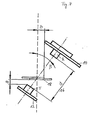
- Fig. 7 schematically shows the alignment of the transmitter T and receiver R at an intersection angle with the plane of the recording medium 18.
- the oblique arrangement of the radiation axis relative to the recording media also has the advantage of avoiding standing waves in continuous operation.
- the inclination angle ⁇ is preferably provided in the range +/- 45 °.
- the minimum distance a between the transmitter edge and the lower edge of the recording medium should be approximately in the range of 5 to 10 mm.
- the minimum distance b may be about 2 to 15 mm, in particular 10 mm. This distance b depends on the selected multiple or double arched threshold and the sheet material.
- the distance d is technically feasible in the range of 10 to 90 mm, and usually in the range of 20 to 80 mm, with an optimum range of about 45 mm.
- FIGS. 8a, b, c show in a simplified representation of principle curves using measured value curves MK, the idealized correction characteristics KK are subjected to the desired target characteristics ZK for reliable detection in the fundamentally different cases of double-sheet recognition and / or a label recognition to achieve.
- the present invention is therefore based on a further important idea, the improvements which are achieved by means of electrical isolation and mechanical decoupling of the transmitter side from the receiver side, with the characteristic correction method, e.g. according to P 10 2004 056 742.5.
- correction characteristics to improve the detection of recording media as a multiple sheet or scattered sheet assumes that without their use and approximately linear reinforcement of the receiver side received signal with further filtering and evaluation, depending on the grammage or the basis weight or the corresponding material damping is obtained, a characteristic curve for the amplified measurement signal is obtained, which is substantially non-linear, in particular exponential, multiply exponential, hyperbolic or similar falling, with over the large, desired range of weights often an uncertain and faulty detection is present.
- correction characteristics changes and improves this, so that the evaluation circuit subsequent to the receiver can be impressed with a corresponding correction characteristic, also as a combination of several correction characteristics, in order to achieve a well-evaluable target characteristic over the desired grammage range for the safe detection with the decision to reach if an isolated one Record carrier, a multiple or double sheet or no sheet is present.
- an ideal target characteristic is intended as a horizontally extending line without slope for the multiple sheet detection, in order to achieve reliable detection with the greatest possible distance from the air threshold or lower double arch threshold. This applies over the entire grammage range, which, taking into account galvanic separation and mechanical decoupling, can be extended up to a range of approx.
- a teach-in process can be provided on a recording medium or on an isolated planar material in combination with the method of the correction characteristic in the device to expand the material spectrum to be detected again.
- the specific correction characteristic is to be taken such that a target characteristic with linear progression and maximum slope of the corresponding straight line is achieved.
- Fig. 8a an idealized example of the curves in the method of the correction characteristic for the multiple or double sheet detection.
- the example after Fig. 8b shows corresponding curves of the curves for the process of the correction characteristic in the label recognition and the detection of such objects, such as adhering to carrier material applied other materials.
- the measured value characteristic MK E is shown as an example with a solid line.
- the ideal target characteristic ZK E represents a straight line with a negative slope or a high voltage swing.
- the correction characteristic KK E required for the transformation is shown, for example, with an interrupted polyline and, in this case, has a point of discontinuity at the intersection between measured value characteristic MK E and target characteristic ZK E.
- Fig. 8c schematically shows the course of the characteristic curves according to the method of the correction characteristic for the single or
- the plotted measured characteristic curve MK DB could be transformed into the target characteristic ZK DBr by impressing, for example, the correction characteristic KK DB , as an upper, solid line trace . The transformation is indicated by the arrows P.
- the invention therefore makes possible a further widening of the material spectrum while at the same time improving the signal sensitivity and largely eliminating interference effects, without requiring a teach-in step for the purposeful recognition of separated recording media.
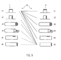
- Fig. 9 shows, for example, various schematically illustrated embodiments of the sensor device 10 with (a3, a4, a5, a6; b3, b4, b5, b6) and without (a1, a2; b1, b2) housings.
- the sensor devices 10 with and without housing can be combined as desired.
- a sensor device 10 which consists of transmitter T and receiver R, not for transmitter T and receiver R similar housing designs, if any, exhibit.
- Especially suitable for housings are cylindrical (al-a4; b1-b4) and cuboid (a5, a6; b5, b6) housings. Economic efficiency can be achieved by omitting a housing for the sensor devices 10 completely.
- the converter has a transducer recording, which in turn allows the sensor device 10 or parts thereof to be taken in a device housing which of printing units such as office equipment such as scanners, printing units, copiers, but also in Geldippozelnern, voting and printing machines to provide.
- printing units such as office equipment such as scanners, printing units, copiers, but also in Geldippozelnern, voting and printing machines to provide.
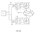
- FIGS. 10a . 10b is a schematic and Blockschaltartiger representation a possibility of galvanic isolation for the supply of transmitter T and receiver R shown.
- the same reference numerals designate the same objects or assemblies corresponding to the preceding figures.
- Transmitter T and receiver R can operate optically, inductively, capacitively or operated on ultrasound basis.
- the galvanic isolation is in Fig. 10a realized in that the receiver R receives a separate power supply from a generator G 1 or power supply.
- the transmitter T is powered by a completely separate generator G 2 or power supply.
- no signal lines are present between transmitter T and receiver R.
- the supply or supply of the sensor device with the transmitter T and the receiver R follows Fig. 10b via a supply block G as a generator or power supply.
- the galvanic separation of transmitter T and receiver R required according to the invention is achieved in this case by at least one galvanic separation unit, eg a transformer 61, in the supply branch 65.
- a further separate galvanic isolation by a transformer 62 in the other supply branch 66 is also provided for the transmitter T.
- no signal lines between transmitter T and receiver R are present.
Landscapes
- Geophysics And Detection Of Objects (AREA)
- Controlling Sheets Or Webs (AREA)
- Length Measuring Devices Characterised By Use Of Acoustic Means (AREA)
Applications Claiming Priority (1)
| Application Number | Priority Date | Filing Date | Title |
|---|---|---|---|
| DE102005026200A DE102005026200A1 (de) | 2005-06-07 | 2005-06-07 | Detektion und Vorrichtung zur Detektion von Aufzeichnungsträgern |
Publications (2)
| Publication Number | Publication Date |
|---|---|
| EP1731455A1 EP1731455A1 (de) | 2006-12-13 |
| EP1731455B1 true EP1731455B1 (de) | 2009-12-30 |
Family
ID=36940259
Family Applications (1)
| Application Number | Title | Priority Date | Filing Date |
|---|---|---|---|
| EP06011005A Active EP1731455B1 (de) | 2005-06-07 | 2006-05-29 | Detektion und Vorrichtung zur Detektion von Aufzeichnungsträgern |
Country Status (4)
| Country | Link |
|---|---|
| US (2) | US8266965B2 (https=) |
| EP (1) | EP1731455B1 (https=) |
| JP (1) | JP2007022808A (https=) |
| DE (2) | DE102005026200A1 (https=) |
Families Citing this family (20)
| Publication number | Priority date | Publication date | Assignee | Title |
|---|---|---|---|---|
| JP4274253B2 (ja) | 2007-02-01 | 2009-06-03 | 株式会社デンソー | エンジン制御装置およびプログラム |
| JP4812114B2 (ja) * | 2007-02-23 | 2011-11-09 | オムロン株式会社 | 紙葉類重送検知装置及び紙葉類重送検知方法 |
| JP4717850B2 (ja) * | 2007-03-14 | 2011-07-06 | シャープ株式会社 | 超音波センサを備えたシート体処理装置 |
| DE102010010139B4 (de) | 2009-03-25 | 2025-11-06 | Heidelberger Druckmaschinen Ag | Verfahren zum Überwachen eines Aufdrucks auf einem Bedruckstoff |
| JP5214757B2 (ja) * | 2011-03-07 | 2013-06-19 | 株式会社東芝 | 状態判定装置 |
| EP2529846A1 (de) * | 2011-05-31 | 2012-12-05 | Pepperl & Fuchs GmbH | Ultraschallbaugruppe |
| DE102011106523A1 (de) * | 2011-07-04 | 2013-01-10 | Giesecke & Devrient Gmbh | Prüfgerät und Verfahren zur Kalibrierung eines Prüfgeräts |
| JP6032989B2 (ja) * | 2012-07-26 | 2016-11-30 | キヤノン株式会社 | シート給送装置および画像形成装置 |
| JP5404872B1 (ja) | 2012-08-24 | 2014-02-05 | 株式会社Pfu | 用紙搬送装置、重送判定方法及びコンピュータプログラム |
| JP2015037982A (ja) | 2012-08-24 | 2015-02-26 | 株式会社Pfu | 原稿搬送装置、ジャム判定方法及びコンピュータプログラム |
| JP5404876B1 (ja) | 2012-08-24 | 2014-02-05 | 株式会社Pfu | 用紙搬送装置、ジャム判定方法及びコンピュータプログラム |
| JP5404870B1 (ja) | 2012-08-24 | 2014-02-05 | 株式会社Pfu | 用紙読取装置、ジャム判定方法及びコンピュータプログラム |
| JP5404880B1 (ja) * | 2012-09-14 | 2014-02-05 | 株式会社Pfu | 用紙搬送装置、異常判定方法及びコンピュータプログラム |
| EP2769949B1 (de) * | 2013-02-21 | 2018-05-30 | Pepperl & Fuchs GmbH | Verfahren zum messtechnischen Unterscheiden von Materialbereichen eines blatt-, bahn- oder bogenartigen Materials sowie Vorrichtung hierzu |
| CN104050746B (zh) | 2014-06-30 | 2017-04-26 | 广州广电运通金融电子股份有限公司 | 一种厚度检测装置 |
| DE102014115592A1 (de) * | 2014-10-27 | 2016-04-28 | Endress + Hauser Flowtec Ag | Anordnung zum Aussenden und/oder Empfangen eines Ultraschall-Nutzsignals und Ultraschall-Durchflussmessgerät |
| DE102015113561A1 (de) * | 2015-08-17 | 2017-02-23 | Endress + Hauser Flowtec Ag | Ultraschallwandler zum Einsatz in Ultraschall- Durchflussmessgeräten zur Messung der Durchflussgeschwindigkeit oder dem Volumendurchfluss von Medien in einer Rohrleitung sowie ein Verfahren zur Herstellung eines solchen Ultraschallwandlers |
| WO2020209834A1 (en) | 2019-04-08 | 2020-10-15 | Hewlett-Packard Development Company, L.P. | Devices for retaining articles |
| CN114040796A (zh) * | 2019-07-16 | 2022-02-11 | 斯迈索尼卡股份有限公司 | 超声设备以及相关使用方法 |
| DE102022124937A1 (de) * | 2022-09-28 | 2024-03-28 | Valeo Schalter Und Sensoren Gmbh | Ultraschallsensor für ein kraftfahrzeug, kraftfahrzeug und herstellungsverfahren für einen ultraschallsensor |
Family Cites Families (58)
| Publication number | Priority date | Publication date | Assignee | Title |
|---|---|---|---|---|
| US3961323A (en) | 1971-02-22 | 1976-06-01 | American Multi-Lert Corporation | Cargo monitor apparatus and method |
| US3771117A (en) * | 1972-03-01 | 1973-11-06 | Westinghouse Electric Corp | Transducer installation |
| US4066969A (en) * | 1975-09-22 | 1978-01-03 | Eastman Kodak Company | Multiple sheet detecting apparatus |
| DE2629562C2 (de) * | 1976-07-01 | 1982-06-24 | Danfoss A/S, 6430 Nordborg | Gerät zur Ultraschallmessung |
| US4201093A (en) * | 1978-07-20 | 1980-05-06 | Metriguard, Inc. | Ultrasonic sheet material testing apparatus |
| JPS56108140U (https=) * | 1980-01-17 | 1981-08-22 | ||
| DE3025788C2 (de) | 1980-07-08 | 1985-07-04 | Danfoss A/S, Nordborg | Ultraschall-Meßgerät |
| DE3048710A1 (de) | 1980-12-23 | 1982-07-15 | GAO Gesellschaft für Automation und Organisation mbH, 8000 München | "verfahren zur pruefung des flaechengewichts von duennem material" |
| US4368438A (en) * | 1981-01-26 | 1983-01-11 | Oce-Nederland B.V. | System for detecting sheet-like objects |
| US4462587A (en) * | 1981-09-25 | 1984-07-31 | Diebold Incorporated | Method of and system for detecting bill status in a paper money dispenser |
| DE3236017C2 (de) * | 1982-09-29 | 1984-10-31 | Fraunhofer-Gesellschaft zur Förderung der angewandten Forschung e.V., 8000 München | Verfahren zum zerstörungsfreien Prüfen eines Werkstückes |
| US4643089A (en) * | 1985-01-18 | 1987-02-17 | Pitney Bowes Inc. | Apparatus for controlling printing means |
| DD238955A1 (de) * | 1985-07-04 | 1986-09-10 | Polygraph Leipzig | Verfahren und einrichtung zur kontrolle von fehl- und/oder mehrfachbogen |
| DK163451C (da) * | 1987-08-05 | 1992-07-20 | Eskofot As | Fremgangsmaade til detektion af isaer tynde folier |
| IT1229180B (it) * | 1988-04-08 | 1991-07-23 | Pitney Bowes Plc | Apparecchiatura per la manipolazione di carta. |
| US5274242A (en) * | 1989-10-10 | 1993-12-28 | Unisys Corporation | Selectible transport-servo velocity profile for document transport |
| US5373482A (en) * | 1990-02-26 | 1994-12-13 | Trend Tec Inc. | Distance measuring system arranged to limit false indications of distance measurements |
| DE4022325C2 (de) * | 1990-07-13 | 2001-06-07 | Roland Man Druckmasch | Akustische Vereinzelungskontrolle |
| DE69217994T2 (de) * | 1991-07-25 | 1997-09-04 | Whitaker Corp | Flüssigkeitsstandsmesser |
| US5279403A (en) * | 1992-07-23 | 1994-01-18 | Crane & Company, Inc. | Microwave security thread detector |
| DE4233855C2 (de) * | 1992-10-08 | 1998-04-30 | Leuze Electronic Gmbh & Co | Verfahren zur Kontrolle von Bögen |
| DE4403011C1 (de) * | 1994-02-01 | 1995-02-16 | Fraunhofer Ges Forschung | Verfahren zur Vereinzelung von unmagnetischen Blechen |
| GB9508654D0 (en) * | 1995-04-28 | 1995-06-14 | Kodak Ltd | Sheet material detector |
| DE19521159C2 (de) * | 1995-06-09 | 1998-05-14 | Porsche Ag | Betätigungsvorrichtung für eine Feststellbremse |
| DE19613311C2 (de) * | 1996-04-03 | 1998-04-09 | Hydrometer Gmbh | Ultraschall-Strömungsmeßgerät für flüssige und/oder gasförmige Medien |
| DE19701644A1 (de) * | 1997-01-18 | 1998-07-23 | Heidelberger Druckmasch Ag | Einrichtung zur Steuerung der Bogenzufuhr zu einer drucktechnischen Maschine |
| GB9723306D0 (en) * | 1997-11-05 | 1998-01-07 | Ncr Int Inc | System for detecting superposed sheets |
| DE29722715U1 (de) * | 1997-12-30 | 1999-04-29 | Klaschka GmbH & Co, 75233 Tiefenbronn | Blechdicken-Meßeinrichtung |
| DE59911895D1 (de) * | 1998-10-20 | 2005-05-19 | Siemens Ag | Verfahren zur Betriebsoptimierung eines Ultraschall-Näherungsschalters und Ultraschall-Näherungsschalters mit Betriebsoptimierung |
| JP2000172897A (ja) * | 1998-12-04 | 2000-06-23 | Hitachi Asahi Electronics Co Ltd | 光学式2枚検知装置のセンサ調光方法 |
| US6281679B1 (en) * | 1998-12-21 | 2001-08-28 | Honeywell - Measurex | Web thickness measurement system |
| US6212130B1 (en) * | 1999-03-08 | 2001-04-03 | Scan-Optics, Inc. | Method and apparatus for plural document detection |
| DE19921217B4 (de) * | 1999-05-07 | 2004-11-25 | Leuze Electronic Gmbh + Co Kg | Vorrichtung zur Detektion von Etiketten |
| DE19927865B4 (de) * | 1999-05-07 | 2005-12-01 | Leuze Electronic Gmbh & Co Kg | Vorrichtung zur Detektion von Objekten |
| CA2397218A1 (en) * | 2000-01-26 | 2001-04-05 | Kba-Giori S.A. | Device and method for detecting paper sheets |
| US6511064B1 (en) * | 2000-04-19 | 2003-01-28 | Eastman Kodak Company | Method and apparatus for multiple document detection using ultrasonic phase shift amplitude |
| US6407599B1 (en) * | 2000-05-10 | 2002-06-18 | Eastman Kodak Company | Method and apparatus for determining a digital phase shift in a signal |
| DE20018193U1 (de) * | 2000-10-25 | 2001-01-04 | Leuze Electronic Gmbh + Co, 73277 Owen | Vorrichtung zur Kontrolle von Bögen |
| US20020062681A1 (en) * | 2000-11-30 | 2002-05-30 | Livingston Richard A. | Oxygen sensor and flow meter device |
| DE10216742B4 (de) | 2001-05-21 | 2008-03-27 | Heidelberger Druckmaschinen Ag | Einrichtung zur Detektion eines Druckproduktes beim Fördern durch eine drucktechnische Maschine |
| DE10233052A1 (de) | 2002-07-19 | 2004-02-05 | Giesecke & Devrient Gmbh | Erkennung von Mehrfachabzügen |
| US7025348B2 (en) * | 2002-11-25 | 2006-04-11 | Eastman Kodak Company | Method and apparatus for detection of multiple documents in a document scanner using multiple ultrasonic sensors |
| DE10255741A1 (de) * | 2002-11-28 | 2004-06-09 | Endress + Hauser Conducta Gesellschaft für Mess- und Regeltechnik mbH + Co. KG | Modularer Messumformer mit galvanisch getrennten Messfühler |
| US6918587B2 (en) * | 2002-12-18 | 2005-07-19 | International Business Machines Corporation | Adaptive and predictive document tracking system |
| US7130245B2 (en) * | 2003-01-31 | 2006-10-31 | Canon Denshi Kabushiki Kaisha | Ultrasonic double feed detecting device |
| DE20312388U1 (de) * | 2003-03-23 | 2003-11-20 | Pepperl + Fuchs GmbH, 68307 Mannheim | Vorrichtung zur berührungslosen Detektion von Unregelmäßigkeiten der Dicke von flächigen Objekten, wie Papier, Pappe, Folien, Bleche oder Etiketten |
| DE10327389B3 (de) * | 2003-06-18 | 2004-12-16 | Leuze Electronic Gmbh + Co. Kg | Sensoranordnung |
| JP4259238B2 (ja) * | 2003-09-09 | 2009-04-30 | コニカミノルタビジネステクノロジーズ株式会社 | 重送検知装置および画像形成装置 |
| JP4377666B2 (ja) * | 2003-12-04 | 2009-12-02 | ニスカ株式会社 | シート供給装置並びに画像読取装置 |
| JP2005162424A (ja) * | 2003-12-04 | 2005-06-23 | Nisca Corp | シート供給装置及びこれを用いた画像読取装置 |
| DE102004056742A1 (de) * | 2004-01-07 | 2005-09-15 | Pepperl + Fuchs Gmbh | Verfahren und Vorrichtung zur berührungslosen Detektion von flächigen Objekten |
| EP1701902B1 (de) | 2004-01-07 | 2014-07-09 | Pepperl + Fuchs GmbH | Verfahren und vorrichtung zur berührungslosen detektion von flächigen objekten |
| DE202004006285U1 (de) | 2004-04-21 | 2004-07-15 | Maschinenbau Oppenweiler Binder Gmbh & Co. Kg | Rundstapelbogenanleger |
| US7669844B2 (en) * | 2004-04-26 | 2010-03-02 | Sharp Kabushiki Kaisha | Paper feeder |
| MXPA06015102A (es) * | 2004-07-01 | 2007-02-08 | Diebold Inc | Metodo y aparato detector de hojas multiples de maquina bancaria automatizada. |
| DE102004034248A1 (de) * | 2004-07-14 | 2006-02-02 | Endress + Hauser Flowtec Ag, Reinach | Elektronische Schaltung mit galvanisch getrennten Baugruppen |
| JP4643296B2 (ja) * | 2005-02-08 | 2011-03-02 | 日立オムロンターミナルソリューションズ株式会社 | 紙幣鑑別装置 |
| EP1717153B1 (de) * | 2005-04-30 | 2008-08-20 | Leuze electronic GmbH + Co. KG | Vorrichtung zur Detektion von Etiketten auf einem Trägermaterial |
-
2005
- 2005-06-07 DE DE102005026200A patent/DE102005026200A1/de not_active Ceased
-
2006
- 2006-05-29 EP EP06011005A patent/EP1731455B1/de active Active
- 2006-05-29 DE DE502006005765T patent/DE502006005765D1/de active Active
- 2006-06-07 US US11/422,682 patent/US8266965B2/en active Active
- 2006-06-07 JP JP2006158278A patent/JP2007022808A/ja active Pending
-
2012
- 2012-07-26 US US13/558,438 patent/US8966983B2/en active Active
Also Published As
| Publication number | Publication date |
|---|---|
| JP2007022808A (ja) | 2007-02-01 |
| DE102005026200A1 (de) | 2006-12-21 |
| EP1731455A1 (de) | 2006-12-13 |
| DE502006005765D1 (de) | 2010-02-11 |
| US20130152689A1 (en) | 2013-06-20 |
| US20070007721A1 (en) | 2007-01-11 |
| US8266965B2 (en) | 2012-09-18 |
| US8966983B2 (en) | 2015-03-03 |
Similar Documents
| Publication | Publication Date | Title |
|---|---|---|
| EP1731455B1 (de) | Detektion und Vorrichtung zur Detektion von Aufzeichnungsträgern | |
| DE102007046031B4 (de) | Ultraschallsensor | |
| EP1067053B1 (de) | Vorrichtung zur Detektion von Objekten | |
| DE102006005048B4 (de) | Ultraschallsensor mit Sendeeinrichtung und Empfangseinrichtung für Ultraschallwellen | |
| DE2929981C2 (de) | Vorrichtung zur Anzeige einer Tonerrestmenge in einem Tonerbehälter | |
| WO2006119926A1 (de) | Einrichtung zum feststellen von dicken und dickenvariationen | |
| EP1059620B1 (de) | Piezo-Effekt-basiertes Sicherheitsmerkmal an Wert- und Sicherheitsdokumenten und dazugehöriges Nachweisverfahren | |
| EP2173618B1 (de) | Robuster kapazitiver abstandssensor | |
| DE102004061759B4 (de) | Verfahren und Vorrichtung zur berührungslosen Detektion von geschichteten flächigen Objekten | |
| DE102008054319B4 (de) | Erfassungsvorrichtung für eine Seitenkollision bei einem Fahrzeug und Fahrgastschutzsystem, das diese Erfassungsvorrichtung aufweist | |
| WO2000019191A1 (de) | Vorrichtung zur ultraschallprüfung von blattgut | |
| DE10139158C1 (de) | Bauelemente-Erfassungsvorrichtung, Bauelemente-Zuführvorrichtung und Verfahren zum Zuführen von Bauelementen mittels einer Bauelemente-Zuführvorrichtung | |
| EP1701902B1 (de) | Verfahren und vorrichtung zur berührungslosen detektion von flächigen objekten | |
| DE202005011034U1 (de) | Vorrichtung zur Detektion von Aufzeichnungsträgern | |
| EP3329473A1 (de) | Einrichtung und verfahren zur untersuchung von wertdokumenten und / oder des transports von wertdokumenten mittels ultraschall | |
| DE112018002734T5 (de) | Objekterfassungssystem | |
| DE102008036597A1 (de) | Verfahren und Vorrichtung zur Bearbeitung von Wertdokumenten | |
| DE102005028214A1 (de) | Vibrationsmesssystem | |
| EP1701900B1 (de) | Verfahren und vorrichtung zur berührungslosen detektion von flächigen objekten | |
| DE10028523B4 (de) | Vorrichtung zum Messen der Höhe eines Bogenstapels unter Verwendung eines im Reflexbetrieb arbeitenden Strahlungsdetektors | |
| EP1701901B1 (de) | Verfahren und vorrichtung zur berührungslosen detektion von flächigen objekten | |
| EP1182434B1 (de) | Multi-Frequenz-Füllstandmessradargerät | |
| DE10327389B3 (de) | Sensoranordnung | |
| DE102008039221A1 (de) | Vorrichtung zur berührungslosen Kontrolle von flächigen Objekten | |
| DE19941728B4 (de) | Bogenkantendetektor |
Legal Events
| Date | Code | Title | Description |
|---|---|---|---|
| PUAI | Public reference made under article 153(3) epc to a published international application that has entered the european phase |
Free format text: ORIGINAL CODE: 0009012 |
|
| AK | Designated contracting states |
Kind code of ref document: A1 Designated state(s): AT BE BG CH CY CZ DE DK EE ES FI FR GB GR HU IE IS IT LI LT LU LV MC NL PL PT RO SE SI SK TR |
|
| AX | Request for extension of the european patent |
Extension state: AL BA HR MK YU |
|
| 17P | Request for examination filed |
Effective date: 20070222 |
|
| 17Q | First examination report despatched |
Effective date: 20070323 |
|
| AKX | Designation fees paid |
Designated state(s): CH DE LI |
|
| GRAP | Despatch of communication of intention to grant a patent |
Free format text: ORIGINAL CODE: EPIDOSNIGR1 |
|
| GRAS | Grant fee paid |
Free format text: ORIGINAL CODE: EPIDOSNIGR3 |
|
| GRAA | (expected) grant |
Free format text: ORIGINAL CODE: 0009210 |
|
| AK | Designated contracting states |
Kind code of ref document: B1 Designated state(s): CH DE LI |
|
| REG | Reference to a national code |
Ref country code: CH Ref legal event code: EP |
|
| REG | Reference to a national code |
Ref country code: CH Ref legal event code: NV Representative=s name: BOGENSBERGER PATENT- & MARKENBUERO DR. BURKHARD BO |
|
| REF | Corresponds to: |
Ref document number: 502006005765 Country of ref document: DE Date of ref document: 20100211 Kind code of ref document: P |
|
| PLBE | No opposition filed within time limit |
Free format text: ORIGINAL CODE: 0009261 |
|
| STAA | Information on the status of an ep patent application or granted ep patent |
Free format text: STATUS: NO OPPOSITION FILED WITHIN TIME LIMIT |
|
| 26N | No opposition filed |
Effective date: 20101001 |
|
| REG | Reference to a national code |
Ref country code: CH Ref legal event code: PCAR Free format text: NEW ADDRESS: FALLSGASSE 7, 9492 ESCHEN (LI) |
|
| REG | Reference to a national code |
Ref country code: DE Ref legal event code: R082 Ref document number: 502006005765 Country of ref document: DE Representative=s name: SCHIFFER, AXEL, DIPL.-PHYS.UNIV. DR.RER.NAT., DE |
|
| PGFP | Annual fee paid to national office [announced via postgrant information from national office to epo] |
Ref country code: CH Payment date: 20180523 Year of fee payment: 13 |
|
| REG | Reference to a national code |
Ref country code: CH Ref legal event code: PL |
|
| PG25 | Lapsed in a contracting state [announced via postgrant information from national office to epo] |
Ref country code: LI Free format text: LAPSE BECAUSE OF NON-PAYMENT OF DUE FEES Effective date: 20190531 Ref country code: CH Free format text: LAPSE BECAUSE OF NON-PAYMENT OF DUE FEES Effective date: 20190531 |
|
| PGFP | Annual fee paid to national office [announced via postgrant information from national office to epo] |
Ref country code: DE Payment date: 20250519 Year of fee payment: 20 |