EP1730404B1 - Diaphragm pump - Google Patents
Diaphragm pump Download PDFInfo
- Publication number
- EP1730404B1 EP1730404B1 EP05724208.3A EP05724208A EP1730404B1 EP 1730404 B1 EP1730404 B1 EP 1730404B1 EP 05724208 A EP05724208 A EP 05724208A EP 1730404 B1 EP1730404 B1 EP 1730404B1
- Authority
- EP
- European Patent Office
- Prior art keywords
- housing
- recited
- diaphragm pump
- pump
- component
- Prior art date
- Legal status (The legal status is an assumption and is not a legal conclusion. Google has not performed a legal analysis and makes no representation as to the accuracy of the status listed.)
- Expired - Lifetime
Links
- 239000012530 fluid Substances 0.000 claims description 6
- 239000000853 adhesive Substances 0.000 description 4
- 230000001070 adhesive effect Effects 0.000 description 4
- 238000010276 construction Methods 0.000 description 4
- 230000003247 decreasing effect Effects 0.000 description 3
- 239000000463 material Substances 0.000 description 3
- 239000000126 substance Substances 0.000 description 3
- 229920002943 EPDM rubber Polymers 0.000 description 2
- 239000004743 Polypropylene Substances 0.000 description 2
- 230000002411 adverse Effects 0.000 description 2
- 125000000484 butyl group Chemical group [H]C([*])([H])C([H])([H])C([H])([H])C([H])([H])[H] 0.000 description 2
- 230000000694 effects Effects 0.000 description 2
- 239000013536 elastomeric material Substances 0.000 description 2
- 238000002347 injection Methods 0.000 description 2
- 239000007924 injection Substances 0.000 description 2
- 238000001746 injection moulding Methods 0.000 description 2
- 238000004519 manufacturing process Methods 0.000 description 2
- -1 polypropylene Polymers 0.000 description 2
- 229920001155 polypropylene Polymers 0.000 description 2
- 229920000181 Ethylene propylene rubber Polymers 0.000 description 1
- 229920005549 butyl rubber Polymers 0.000 description 1
- 238000009434 installation Methods 0.000 description 1
- 230000001788 irregular Effects 0.000 description 1
- 230000010355 oscillation Effects 0.000 description 1
- 229920002379 silicone rubber Polymers 0.000 description 1
Images




Classifications
-
- F—MECHANICAL ENGINEERING; LIGHTING; HEATING; WEAPONS; BLASTING
- F04—POSITIVE - DISPLACEMENT MACHINES FOR LIQUIDS; PUMPS FOR LIQUIDS OR ELASTIC FLUIDS
- F04B—POSITIVE-DISPLACEMENT MACHINES FOR LIQUIDS; PUMPS
- F04B43/00—Machines, pumps, or pumping installations having flexible working members
- F04B43/02—Machines, pumps, or pumping installations having flexible working members having plate-like flexible members, e.g. diaphragms
- F04B43/04—Pumps having electric drive
-
- B—PERFORMING OPERATIONS; TRANSPORTING
- B01—PHYSICAL OR CHEMICAL PROCESSES OR APPARATUS IN GENERAL
- B01L—CHEMICAL OR PHYSICAL LABORATORY APPARATUS FOR GENERAL USE
- B01L3/00—Containers or dishes for laboratory use, e.g. laboratory glassware; Droppers
- B01L3/02—Burettes; Pipettes
- B01L3/021—Pipettes, i.e. with only one conduit for withdrawing and redistributing liquids
-
- B—PERFORMING OPERATIONS; TRANSPORTING
- B01—PHYSICAL OR CHEMICAL PROCESSES OR APPARATUS IN GENERAL
- B01L—CHEMICAL OR PHYSICAL LABORATORY APPARATUS FOR GENERAL USE
- B01L3/00—Containers or dishes for laboratory use, e.g. laboratory glassware; Droppers
- B01L3/02—Burettes; Pipettes
- B01L3/021—Pipettes, i.e. with only one conduit for withdrawing and redistributing liquids
- B01L3/0213—Accessories for glass pipettes; Gun-type pipettes, e.g. safety devices, pumps
-
- F—MECHANICAL ENGINEERING; LIGHTING; HEATING; WEAPONS; BLASTING
- F04—POSITIVE - DISPLACEMENT MACHINES FOR LIQUIDS; PUMPS FOR LIQUIDS OR ELASTIC FLUIDS
- F04B—POSITIVE-DISPLACEMENT MACHINES FOR LIQUIDS; PUMPS
- F04B45/00—Pumps or pumping installations having flexible working members and specially adapted for elastic fluids
- F04B45/04—Pumps or pumping installations having flexible working members and specially adapted for elastic fluids having plate-like flexible members, e.g. diaphragms
- F04B45/047—Pumps having electric drive
-
- F—MECHANICAL ENGINEERING; LIGHTING; HEATING; WEAPONS; BLASTING
- F04—POSITIVE - DISPLACEMENT MACHINES FOR LIQUIDS; PUMPS FOR LIQUIDS OR ELASTIC FLUIDS
- F04B—POSITIVE-DISPLACEMENT MACHINES FOR LIQUIDS; PUMPS
- F04B53/00—Component parts, details or accessories not provided for in, or of interest apart from, groups F04B1/00 - F04B23/00 or F04B39/00 - F04B47/00
- F04B53/22—Arrangements for enabling ready assembly or disassembly
-
- B—PERFORMING OPERATIONS; TRANSPORTING
- B01—PHYSICAL OR CHEMICAL PROCESSES OR APPARATUS IN GENERAL
- B01L—CHEMICAL OR PHYSICAL LABORATORY APPARATUS FOR GENERAL USE
- B01L2400/00—Moving or stopping fluids
- B01L2400/04—Moving fluids with specific forces or mechanical means
- B01L2400/0475—Moving fluids with specific forces or mechanical means specific mechanical means and fluid pressure
- B01L2400/0487—Moving fluids with specific forces or mechanical means specific mechanical means and fluid pressure fluid pressure, pneumatics
Definitions
- the present invention relates to a diaphragm pump that can be assembled by hand.
- the invention relates to a miniature diaphragm pump having a reduced number of components that can be connected without the use of tools, extraneous fasteners or adhesives.
- Miniature diaphragm pumps are well known in the prior art. Typically, known miniature diaphragm pumps are made from multiple prefabricated components that are connected using screws, adhesives, bands, and/or other fasteners. Assembly of the pump components is labor intensive and time consuming, especially when at least one hand tool is required to install the fasteners. Therefore, it would be desirable to provide a miniature diaphragm pump that can be assembled by hand from components that are self-locking.
- the pressure and vacuum ports are oriented at a 90-degree angle relative to the axis of movement of the linearly-reciprocating diaphragm.
- This design typically requires at least three separate housing components that must be arranged and connected in a stacked configuration.
- Document DE 43 13 370 A1 describes a diaphragm pump having a pump housing as defined in the preamble of patent claim 1.
- the pump according to this prior art document comprises three components (10, 30 and 80) that may form the housing, wherein said components each connect along planar interfaces using screws inserted in corner holes (13, 34, and 83) respectively.
- US Patent 5,214,968 discloses a pipette gun including a pump comprising a housing made of housing components which connect along planar interfaces.
- the present invention provides a miniature diaphragm pump that can be assembled by hand from components that are self-locking. As a result, the cost and amount of time required to assemble the diaphragm pump is reduced compared to known miniature diaphragm pumps.
- the housing of the pump is made of only two housing components.
- the bi-component housing has a top component and a bottom component that connect along first and second complimenting connection interfaces, that are inclined relative to one another, and form an interior pump chamber, an exterior pressure port, an exterior vacuum port, and fluid communication channels connecting the exterior ports with the interior chamber.
- the first and second connection interfaces are inclined relative to one another.
- the first and second connection interfaces of the bottom component are oriented at an obtuse angle
- the first and second connection interfaces of the top component are arranged at an angle greater than 180 degrees.
- Each of the bottom and top components has a plurality of exterior surfaces that form the exterior of the housing.
- the bottom component has a base.
- a valve block is formed on one end of the base.
- a first connection interface and diaphragm seat are formed at the other end of the base.
- the valve block includes opposed exterior side surfaces, an exterior rear surface, and a second interior connection interface.
- the pressure and vacuum ports are formed on the exterior rear surface of the valve block. Channels extend through the valve block from the pressure port and vacuum port, respectively, to the second connection interface.
- the top component has a base. An interior cavity and a first connection interface are formed at one end of the base. A valve head is formed at the other end of the base. The valve head includes a second connection interface. Channels extend through the valve block from the second connection interface to the interior cavity. The channels of the top and bottom components align and form the fluid communication channels of the housing when the first component and second component are connected.
- the pump includes means for self-locking the top component to the bottom component with the first interior interfaces and the second interior interfaces in contact with one another.
- the self-locking means creates a compressive force on both connection interfaces of the top and bottom components.
- the self-locking means comprises a housing cover.
- the housing cover slidably engages and clamps together the top and bottom components.
- the cover has opposed, interior edges that engage the exterior surfaces of the top and bottom component. The edges comprise tapered grooves on the interior of the cover that slidably engage the elongate exterior edges of the top and bottom components.
- the cover includes a snap-lock that engages the bottom component.
- the snap lock comprises a detent protruding from an exterior side surface of the first component that cooperatively engages a notch in the cover.
- the self-locking means comprises clips that clamp the top and bottom component together.
- the self locking means comprises interlocking tabs and slots that are integrally formed on the top and bottom components, respectively.
- the diaphragm pump includes a motor having a rotating output shaft, and a linearly oscillating diaphragm mounted inside the housing and connected to the pump shaft.
- the housing includes means for self-locking the motor to the housing.
- the bottom component includes a pump mount adapted to connect the pump motor to the bottom component.
- the pump mount is integrally formed with the bottom component.
- the pump mount comprises a pair of elastically-deformable, U-shaped mounts on the bottom component.
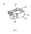
- Fig. 1 is a first perspective view of a diaphragm pump in accordance with an embodiment of the invention
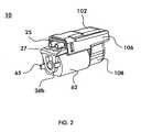
- Fig. 2 is a second perspective view of the diaphragm pump shown in Fig. 1 ;
- Figs. 3 and 4 are exploded perspective views of the diaphragm pump shown in Fig. 1 ;
- Fig. 5 is a side elevational view of the motor being installed on the bottom component of the diaphragm pump shown in Fig. 1 ;
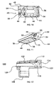
- Figs. 6 and 7 are side elevational views of the cover (partially revealed) being installed over the top and bottom components of the diaphragm pump shown in Fig. 1 ;
- Fig. 8 is an enlarged perspective view of the second connection interface of the bottom component shown in Fig. 3 ;
- Fig. 9 is an enlarged, top plan view of the valve gasket shown in Fig. 3 ;
- Fig. 10 is a bottom plan view of the top component shown in Fig. 3 ;
- Fig. 11 is a perspective view of the top component shown in Fig. 3 ;
- Fig. 12 is a cross-sectional view of the cover taken along the axis L-L of Fig. 4 .
- Figs. 13-15 are perspective views of a diaphragm pump in accordance with another embodiment of the invention.
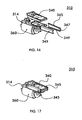
- Figs. 16 and 17 are perspective views of a diaphragm pump in accordance with a further embodiment of the invention.
- Fig. 18 is a schematic view of a pipette gun having a diaphragm pump in accordance with an embodiment of the invention.
- the term "hand assembled” shall mean capable of being assembled by hand without the use of tools of any kind.
- the term “self-locking” as applied to components shall mean that the components are capable of engaging and locking to one another without the use of extraneous fasteners, adhesives or other components.
- a diaphragm pump in accordance with a preferred embodiment of the present invention is designated generally by reference numeral 10.
- the pump 10 can be hand assembled from components that are self-locking.
- the pump 10 has a bi-component housing comprising a bottom or first component 14 and top or second component 40.
- the bottom 14 and top 40 components connect along first and second complimenting connection interfaces and form an interior pump chamber, an exterior vacuum port 25, an exterior pressure port 27, and fluid communication channels connecting the exterior ports 25, 27 with the interior chamber.
- the pressure port 25 and vacuum port 27 have parallel and coplanar lengthwise extending axes.
- the top housing component 40 is made by injection molding and is formed as a single, integrated part.
- the bottom housing component 14 is preferably made by injection molding and is formed as a single, integrated part.
- the housing components 14, 40 are preferably manufactured from an injection moldable material that is resistant to chemical attack.
- the material from which the bottom component 14 is made is also preferably elastically deformable so that the U-shaped motor mounts 36, described below, can be deflected during installation of the motor 60.
- the top and bottom components 40,14 may be made of polypropylene.
- the bottom component 14 has a generally rectangular, planar base. Referring to the orientation shown in Figs. 3 and 4 , a bottomless cavity 22 and a first interior connection interface 18 are formed on one end of the top side of the base. A valve block 24 is formed on the other end of the top side of the base. A pair of opposed U-shaped motor mounts 36a,36b extends from the bottom side of the base. A pair of alignment bores 34 is formed in the first interior connection interface 18.
- the first interior connection interface 18 is generally co-planar with the base and extends around the perimeter of the bottomless cavity 22.
- a recessed diaphragm seat 20 is formed on the perimeter of the cavity 22.
- An elastic diaphragm 76 sits in the diaphragm seat 20 and reciprocates within the cavity 22.
- the valve block 24 is preferably integrally formed with the base of the bottom component 14.
- the exterior surface of the valve block 24 includes opposed side surfaces 26a, 26b and a rear surface 26c.
- the valve block 24 has a second interior connection interface 28 that is contiguous with the first interior connection interface 18, but is oriented upwardly and inclined at an angle ⁇ 1 relative the first interior connection interface 18 as shown in Fig. 5 .
- the angle ⁇ 1 is approximately 135 degrees.
- the angle ⁇ 1 may be increased or decreased. However, reducing the angle ⁇ 1 to a value between 90 degrees and 135 degrees increases the profile or height of the pump, while increasing the angle ⁇ 1 make the components more difficult to manufacture and adversely effects the performance of the valves described below.
- a vacuum port 25 and pressure port 27 are formed on the rear surface 26c of the valve block 24.
- An intake channel 30 and an exhaust channel 32 extend through the valve block 24 from the exterior rear surface 26c to the recessed portion 28a of the second interior connection interface 28.
- a detent 38 extends outwardly from each of the exterior side surfaces 26a, 26b.
- the top component 40 also has a generally rectangular, planar base. As best seen in Figs. 10 and 11 , and referring to the orientation shown therein, the top component has a concave cap portion 46 formed in one end of the bottom surface. The cap portion 46 defines the upper boundary of the interior diaphragm chamber.
- a first interior connection interface 44 extends around the perimeter of the cap portion 46 and is generally co-planar with the base.
- a recessed diaphragm seat 45 is formed on the perimeter of the cavity cap portion 46.
- An elastic diaphragm 76 sits in the diaphragm seat 45 and reciprocates within the cap portion 46.
- a valve head 48 is integrally formed at the other end of the top component 40.
- the valve head 48 has a second interior connection interface 50, which is contiguous with the first interior connection interface 44, but which is inclined at an angle ⁇ 2 relative to the plane of the first interior connection interface 44.
- the angle ⁇ 2 is preferably about 225 degrees as seen in Fig. 5 .
- the angle ⁇ 2 may be increased or decreased. However, increasing the angle ⁇ 2 to a value between 135 degrees and 270 degrees increases the profile or height of the pump, while decreasing the angle ⁇ 2 make the components more difficult to manufacture and adversely effects the performance of the valves described below.
- An intake channel 52 and an exhaust channel 54 extend through the valve head 48 from the second interior connection interface 44 to the inside of the cap portion 46.
- a pair of alignment pins 56 extend downwardly from the first interior connection interface 44 of the top component 40.
- the alignment pins 56 are preferably integrally formed with the top component 40 and are arranged to engage the alignment bores 34 formed in the first interior connection interface 18 of the bottom component 14.
- the top component 40 and bottom component 14 are assembled by overlapping the first interior connection interfaces 18, 44 and the second interior connection interfaces 28, 50, respectively. Once connected, the intake channels 30, 52 and exhaust channels 32, 54 align and form a continuous fluid flow path between the vacuum and pressure ports 25, 27 and the interior diaphragm chamber.
- the pump 10 has a motor 60 removably mounted underneath the bottom component 14.
- the motor 60 is preferably a conventional, miniature D.C. motor having an exterior housing 62, a drive shaft 64, electrical leads 65, and shaft hubs 66a, 66b on each end of the housing 62.
- the motor 60 is mounted in U-shaped mounts 36a, 36b protruding downwardly from the bottom surface of the bottom component 14.
- the U-shaped mounts 36a, 36b are spaced so that the mounts 36a, 36b straddle the motor housing 62 with the shaft hubs 66a, 66b seated in the mounts 36a, 36b as best seen in Figs. 2 and 5 .
- the interior piston assembly includes a piston 70, diaphragm 76, diaphragm cap 78, valve gasket 80, bearing assembly 82, and a counterbalanced eccentric pin 84 as shown in Figs. 3 and 4 .
- the piston 70 preferably includes a piston head 72 and piston arm 74, which are preferably formed as an integral unit. Two mounting posts 73 are formed with and extend transversely to the top surface of the piston head 72. An eyelet 87 is formed in the bottom of the piston arm 74.
- the diaphragm 76 includes two apertures 77, which are arranged to align with the mounting posts 73 of the piston head 72.
- the diaphragm 76 is secured on the piston head 72 by the diaphragm cap 78, which engages the mounting posts 73.
- the piston assembly is self-locking and can be hand assembled by snapping the diaphragm cap 78 onto the mounting posts 73.
- the diaphragm 76 preferably has a rib portion 79 that extends around the periphery of the diaphragm 76. The rib portion 79 sits in the diaphragm seat 20 of the bottom component 14 and the diaphragm seat 45 of the top component 40.
- the piston assembly linearly oscillates along an axis that is perpendicular to the lengthwise axis of the exterior pressure and vacuum ports.
- the pressure and vacuum ports may be oriented at a non-perpendicular angle relative to the axis of oscillation of the piston assembly.
- the piston 70 and diaphragm cap 78 are preferably manufactured from an injection moldable material that is resistant to chemical attack such as polypropylene.
- the diaphragm 70 is preferably made from an elastomeric material that is resistant to chemical attack such as silicone, butyl, or ethylene propylene rubber (EPDM). More preferably, the diaphragm is made from butyl or EPDM.
- a counterbalanced eccentric pin 84 and bearing assembly 82 are installed on the motor drive shaft 64.
- the bearing assembly 82 is mounted in the eyelet 87 of the piston arm 74, while the eccentric pin 84 is mounted on the motor shaft 64.
- the eccentric pin 84, bearing assembly 82, piston arm 74 and drive shaft 64 are connected by interference fits. Therefore, the components of the piston assembly and bearing assembly are self-locking and can be assembled by hand by pressing the components together.
- a gasket 80 seals the interface between the second interior connection interfaces 28, 50 of the bottom component 14 and top component 40, respectively.
- the second interior connection interface 28 of the bottom component 14 has a recessed portion 28a in which the gasket 80 is seated.
- the gasket 80 comprises a flat, generally-rectangular elastomeric material having a rib portion 88 that extends around the periphery of the gasket 80.
- the rib 88 also bifurcates the gasket 80 to isolate the intake side 80a from the exhaust side 80b.
- a horseshoe-shaped perforation 90 forms an intake flap 92 on the intake side 80a of the gasket 80.
- a semi-circular perforation 94 forms an exhaust flap 96 on the exhaust side 80b of the gasket 80.
- an enlarged pocket 97 is formed in the second interface 28 of the bottom component proximate the exhaust channel 32.
- a septum 98 is formed intermediate the pocket 97. The septum 98 limits the path of travel of the exhaust flap 96 within the pocket 97.
- an enlarged pocket 95 is formed in the second interface 50 in the top component proximate the intake channel 52.
- a septum 99 is formed intermediate the pocket 95. The septum limits the path of travel of the intake flap 92 within the pocket 95.
- a cover 100 locks the top component 40 to the bottom component 14 and also reduces the amount of noise emitted by the pump 10.
- the cover 100 has an irregular shape that is symmetrical along a lengthwise axis "L".
- the cover 100 has a top wall 102, opposed side walls 104, 106, a bottom wall 108, rear end 107 and a front end 109.
- the cover 100 has a pair of lengthwise-extending, inwardly-protruding edges 110, 112 formed on the inner surface of each side wall 104, 106.
- the edges 110,112 are skew.
- the first edge 110 is arranged to engage the underside of the lengthwise-extending edge of the bottom component 14.
- the second edge 112 is arranged to engage the upper side of the lengthwise-extending edge of the top component 40.
- the lengthwise-extending axes of the first 110 and second 112 edges are oblique and arranged such that the axes converge extending from the rear end 107 to the front end 109 of the cover 100.
- the taper of the axes of the edges 110, 112 is arranged to generally compliment the tapered angular orientation of the lengthwise-extending edges of the top and bottom components 40,14 and to compress the lengthwise-extending edges when the cover 100 is installed.
- the cover 100 creates a compressive force on both connection interfaces of the top 40 and bottom 14 components.
- Each side portion 104, 106 of the cover 100 has a rectangular aperture 114 proximate the rear end 107.
- the aperture 114 is sized and arranged to engage the detent 38 formed on each of the side surfaces 26a, 26b of the bottom component 14, and to lock the cover 100 the bottom component 14.
- the components of the pump 10 are designed to be quickly hand assembled, without the use of extraneous fasteners or adhesives since the components are self-locking.
- the components either snap-lock together or are press fit together by hand.
- the motor 60 is initially installed on the bottom component 14. Referring to Fig. 5 , the motor 60 is installed by inserting the drive shaft 64 at an angle through the front mount 36a until the front shaft hub 66a is seated in the front mount 36a. The back end of the motor 60 is then pushed upwardly while simultaneously deflecting the back mount 36b until the rear shaft hub 66b is seated in the back mount 36b.
- the piston 70, bearing assembly 82 and counterbalanced eccentric pin 84 are connected to the drive shaft 64 of the motor.
- the bearing assembly 82 is press fitted into the eyelet 87 of the piston arm 74.
- the eccentric pin 84 is then press fitted into the bearing 82 and then press fitted onto the drive shaft 64.
- the diaphragm 76 With the piston head 72 extending through the interior cavity 22, the diaphragm 76 is secured to the piston head 72 by press fitting the diaphragm cap 78 to the mounting posts 73.
- the valve gasket 80 is placed in the recess 28a on the second interior connection interface 28 of the bottom component 14.
- top 40 and bottom 14 components are aligned and locked to one another.
- the top component 40 is aligned with the bottom component 14 by inserting the alignment posts 56 of the top component 40 in the alignment bores 34 of the bottom component 14.
- the cover 100 is then slid over both components until the detents 38 on the bottom component 14 snap into the slots 114 in the side of the cover 100.
- the interior edges 110, 112 of the cover 100 engage and compress the exterior, lengthwise-extending edges of the top 40 and bottom 14 components to clamp the top and bottom components together.
- the cover compresses the first and second connection interfaces of the top 40 and bottom 14 components, respectively.
- FIG. 13-15 An alternative embodiment of the diaphragm pump, designated by reference numeral 210, is shown in Figs. 13-15 .
- the diaphragm pump 210 is similar in construction to the pump 10 described and illustrated above with the exception that the top and bottom components 240,214 are self-locking and do not require a separate locking element, such as the cover 100 described above. For clarity, the components of the piston assembly are omitted from Figs. 13-15 .
- the pump 210 includes a top component 240 and bottom component 214 similar in construction, except as described below, to the top and bottom components 40,14 described above.
- the pump 210 does not include a cover for connecting the top and bottom components 240,214 together. Rather, snap locks are integrally formed on the top and bottom components 240,214 so that the top and bottom components can be snap-locked together and hand assembled.
- the front end of the bottom component 214 includes a nose clip 216 that engages the nose 242 of the top component.
- the top component 240 includes a pair of opposed tabs 243 fixed to and extending from the second connection interface 250.
- the bottom component 214 includes a pair of opposed slots 229 formed in the second connection interface 228. The top and bottom components 240,214 are connected by inserting the nose 242 into the nose clip 216, and then pivoting the top component 240 about the nose 242 until the tabs 243 on the top component 240 snap-lock into the slots 229 in the bottom component 214.
- FIG. 16 and 17 A further embodiment of the diaphragm pump, designated by reference numeral 310, is shown in Figs. 16 and 17 .
- the diaphragm pump 310 is similar in construction to the pump 10 described and illustrated above except that the cover 100 has been replaced with locking clips 345. For clarity, the components of the piston assembly are omitted from Figs. 16 and 17 .
- the pump 310 includes a top component 340 and bottom component 314 similar in construction to the top and bottom components 40,14 described above. However, the pump 310 does not include a cover for connecting the top and bottom components 340,314 together. Rather, the top and bottom components 340,314 are locked together using two clips 345. The clips 345 compresses the first and second connection interfaces of the top 40 and bottom 14 components, respectively.
- the clips 345 are constructed similar to the lengthwise-extending, inwardly protruding edges 110,112 of the cover 100 described above.
- the tapered angular orientation of the upper and lower interior edges 347,349 of the clips 345 are skew, and are arranged to generally compliment the taper of the lengthwise-extending edges of the top and bottom components 240,214, and to compress the lengthwise-extending edges when the clips 345 are installed.
- the top and bottom components 340,314 are connected by overlapping the top and bottom components 340,314, and then sliding the clips from front to back along the lengthwise-extending edges until the top and bottom components 340,314 are firmly compressed together.
- a diaphragm pump 410 is provided in a pipette gun 400 for admitting and emitting fluid from a pipette 417.
- the housing 401 of the pipette gun 400 has a hand grip portion 402 and a barrel portion 403 that is oriented transverse to said hand grip portion.
- a pipette connector 407 is fixed to and is oriented transverse to the end of the barrel portion 403.
- a diaphragm pump 410 is mounted inside the housing 401 of the pipette gun 400.
- the diaphragm pump may be any one of the embodiments of the pump described above.
- An internal conduit 409 connects the pump 410 to the pipette connector 407.
- a positive air flow trigger 411 and a negative air flow trigger 413 on the gun handle are connected to the pump 410 to selectively regulate the flow of either positive air pressure or negative air pressure through the pipette connector 407.
Landscapes
- Engineering & Computer Science (AREA)
- Mechanical Engineering (AREA)
- General Engineering & Computer Science (AREA)
- Health & Medical Sciences (AREA)
- Clinical Laboratory Science (AREA)
- Chemical & Material Sciences (AREA)
- Chemical Kinetics & Catalysis (AREA)
- Reciprocating Pumps (AREA)
Priority Applications (1)
| Application Number | Priority Date | Filing Date | Title |
|---|---|---|---|
| PL05724208T PL1730404T3 (pl) | 2004-03-02 | 2005-03-02 | Pompa membranowa |
Applications Claiming Priority (2)
| Application Number | Priority Date | Filing Date | Title |
|---|---|---|---|
| US10/791,262 US7329104B2 (en) | 2004-03-02 | 2004-03-02 | Split-housing pipette pump |
| PCT/US2005/006614 WO2005085641A1 (en) | 2004-03-02 | 2005-03-02 | Diaphragm pump |
Publications (3)
| Publication Number | Publication Date |
|---|---|
| EP1730404A1 EP1730404A1 (en) | 2006-12-13 |
| EP1730404A4 EP1730404A4 (en) | 2011-03-09 |
| EP1730404B1 true EP1730404B1 (en) | 2013-05-08 |
Family
ID=34911628
Family Applications (1)
| Application Number | Title | Priority Date | Filing Date |
|---|---|---|---|
| EP05724208.3A Expired - Lifetime EP1730404B1 (en) | 2004-03-02 | 2005-03-02 | Diaphragm pump |
Country Status (5)
| Country | Link |
|---|---|
| US (1) | US7329104B2 (pl) |
| EP (1) | EP1730404B1 (pl) |
| JP (1) | JP5224806B2 (pl) |
| PL (1) | PL1730404T3 (pl) |
| WO (1) | WO2005085641A1 (pl) |
Families Citing this family (7)
| Publication number | Priority date | Publication date | Assignee | Title |
|---|---|---|---|---|
| US8714501B2 (en) | 2006-12-14 | 2014-05-06 | Xylem Ip Holdings Llc | Mounting bracket for a pump |
| DE102010038873A1 (de) * | 2010-08-04 | 2012-02-09 | Gardner Denver Thomas Gmbh | Pumpe |
| CN103946550B (zh) * | 2012-03-30 | 2018-04-17 | 四川宏华石油设备有限公司 | 一种钻井泵缸套装配装置 |
| GB2502342A (en) * | 2012-05-25 | 2013-11-27 | Richard Weatherley | Disposable diaphragm pump |
| US9800650B2 (en) * | 2014-03-10 | 2017-10-24 | Vmware, Inc. | Resource management for multiple desktop configurations for supporting virtual desktops of different user classes |
| EP3452721B1 (en) | 2016-05-06 | 2020-04-15 | Graco Minnesota Inc. | Mechanically driven modular diaphragm pump |
| KR102611409B1 (ko) * | 2018-07-26 | 2023-12-06 | 엘지전자 주식회사 | 펌프 조립체 및 이를 구비하는 조리기기 |
Family Cites Families (27)
| Publication number | Priority date | Publication date | Assignee | Title |
|---|---|---|---|---|
| US2748606A (en) * | 1951-11-30 | 1956-06-05 | Cornelius Co | Mechanical movement |
| US3334545A (en) * | 1965-03-10 | 1967-08-08 | Robertshaw Controls Co | Multiple position vacuum actuator |
| CH439121A (fr) * | 1965-04-21 | 1967-12-15 | Virola Sa | Dispositif de fixation d'un spiral d'horlogerie à l'axe de balancier |
| US3416461A (en) * | 1966-09-01 | 1968-12-17 | Hills Mccanna Co | Diaphragm pump |
| US3539276A (en) * | 1968-10-14 | 1970-11-10 | Kinuta Giken Kk | Air supply device |
| JPS4816641Y1 (pl) * | 1969-05-14 | 1973-05-12 | ||
| US3771907A (en) * | 1971-09-13 | 1973-11-13 | Reynolds Products | Simplified positive displacement syrup pump assembly for drink machines |
| US3776666A (en) * | 1972-02-18 | 1973-12-04 | Deknatel Inc | Portable pump |
| JPS5781489U (pl) * | 1980-11-08 | 1982-05-20 | ||
| ATE10670T1 (de) * | 1980-12-29 | 1984-12-15 | Lewa Herbert Ott Gmbh + Co. | Membranpumpe mit druckentlastet eingespannter membran. |
| US4614481A (en) * | 1985-06-10 | 1986-09-30 | Vanderjagt John A | Pump with replaceable cartridge |
| US4675782A (en) * | 1985-12-20 | 1987-06-23 | General Electric Company | Molded plastic enclosure for disconnect switches |
| JPS6314070Y2 (pl) * | 1986-09-02 | 1988-04-20 | ||
| US4794847A (en) * | 1986-11-30 | 1989-01-03 | Kreuter Mfg. Co., Inc. | Rotary actuator |
| US4842498A (en) * | 1987-01-20 | 1989-06-27 | Thomas Industries, Inc. | Diaphragm compressor |
| JP2556671Y2 (ja) * | 1988-10-05 | 1997-12-08 | 世晃産業株式会社 | ダイアフラム式エアポンプにおけるバルブボックス部のゴム栓取付構造 |
| DE3943585C2 (de) * | 1989-08-31 | 1995-04-27 | Wagner Gmbh J | Membranpumpe |
| US5232353A (en) * | 1992-01-06 | 1993-08-03 | Grant Benton H | Pressurized diaphragm pump and directional flow controller therefor |
| US5214968A (en) * | 1992-01-06 | 1993-06-01 | Drummond Scientific Company | Pipet filling and discharge device |
| JP3373558B2 (ja) * | 1992-04-23 | 2003-02-04 | 松下電工株式会社 | 小型ポンプ装置 |
| DE9317083U1 (de) * | 1993-11-09 | 1994-01-13 | Knf-Neuberger Gmbh, 79112 Freiburg | Pumpe mit einem Antriebsmotor und einem Gehäuse |
| DE4426812A1 (de) * | 1994-07-28 | 1996-02-08 | Siemens Ag | Wasserdichtes Gehäuse mit Steckverbindung zum Schutz von Elektronikschaltkreisen |
| US5731763A (en) * | 1995-03-30 | 1998-03-24 | Herweck; Steve A. | Video/TV access controller |
| US5619900A (en) * | 1995-06-07 | 1997-04-15 | Itt Automotive Inc. | Vacuum booster assembly |
| US5615596A (en) * | 1995-11-29 | 1997-04-01 | Innovatec Products International, Inc. | Inflated ball container repressurizer |
| JP2000283044A (ja) * | 1999-03-31 | 2000-10-10 | Erc:Kk | ポンプ |
| JP3834745B2 (ja) * | 1999-05-11 | 2006-10-18 | 応研精工株式会社 | 小型ポンプ |
-
2004
- 2004-03-02 US US10/791,262 patent/US7329104B2/en not_active Expired - Lifetime
-
2005
- 2005-03-02 EP EP05724208.3A patent/EP1730404B1/en not_active Expired - Lifetime
- 2005-03-02 PL PL05724208T patent/PL1730404T3/pl unknown
- 2005-03-02 JP JP2007501905A patent/JP5224806B2/ja not_active Expired - Lifetime
- 2005-03-02 WO PCT/US2005/006614 patent/WO2005085641A1/en not_active Ceased
Also Published As
| Publication number | Publication date |
|---|---|
| US20050196303A1 (en) | 2005-09-08 |
| JP2007526422A (ja) | 2007-09-13 |
| EP1730404A4 (en) | 2011-03-09 |
| US7329104B2 (en) | 2008-02-12 |
| PL1730404T3 (pl) | 2013-12-31 |
| WO2005085641A1 (en) | 2005-09-15 |
| JP5224806B2 (ja) | 2013-07-03 |
| EP1730404A1 (en) | 2006-12-13 |
Similar Documents
| Publication | Publication Date | Title |
|---|---|---|
| JP5111001B2 (ja) | 内燃エンジン | |
| US7329104B2 (en) | Split-housing pipette pump | |
| GB2463824A (en) | Retaining arrangement for a pump fitting | |
| JPH08226383A (ja) | コンプレッサ・真空ポンプ用リードバルブ | |
| RU2472967C2 (ru) | Узел мембранного отсасывателя | |
| US6431845B1 (en) | Head cover assembly with monolithic valve plate | |
| CN107429853B (zh) | 止回阀及阀芯 | |
| EP1627709A3 (en) | A flow guide for fluid driven tools and tools incorporating the same | |
| CN1237228A (zh) | 对制冷压缩机缸盖及消音器的改进 | |
| KR101845124B1 (ko) | 펌프 | |
| CN1266382C (zh) | 用于往复式压缩机的吸入阀 | |
| CN1404554A (zh) | 压缩机阀板 | |
| EP1247022A1 (en) | Pump housing construction | |
| US20050013717A1 (en) | Valve assembly of reciprocating compressor | |
| CN111386417B (zh) | 阀装置、泵头及泵装置 | |
| KR20200017808A (ko) | 밀폐형 압축기용 밸브 장치 및 그 밸브 스톱퍼 | |
| US6832582B2 (en) | Two-stroke engine and method of making the same | |
| EP1022464A2 (en) | Compressor valve | |
| CN210564959U (zh) | 真空吸气泵及其集排气组件 | |
| CN220748491U (zh) | 空压机的进排气结构 | |
| KR100453000B1 (ko) | 밀폐형 압축기의 흡입머플러 장착구조 | |
| KR200163924Y1 (ko) | 압축기의 밸브구조 | |
| KR100340840B1 (ko) | 밀폐형 압축기의 헤드커버 | |
| JP2007009838A (ja) | 小型ダイヤフラムポンプ | |
| KR200163926Y1 (ko) | 압축기의 밸브 고정구조 |
Legal Events
| Date | Code | Title | Description |
|---|---|---|---|
| PUAI | Public reference made under article 153(3) epc to a published international application that has entered the european phase |
Free format text: ORIGINAL CODE: 0009012 |
|
| 17P | Request for examination filed |
Effective date: 20060921 |
|
| AK | Designated contracting states |
Kind code of ref document: A1 Designated state(s): AT BE BG CH CY CZ DE DK EE ES FI FR GB GR HU IE IS IT LI LT LU MC NL PL PT RO SE SI SK TR |
|
| DAX | Request for extension of the european patent (deleted) | ||
| A4 | Supplementary search report drawn up and despatched |
Effective date: 20110208 |
|
| RIC1 | Information provided on ipc code assigned before grant |
Ipc: F04B 45/047 20060101AFI20050920BHEP Ipc: F04B 53/22 20060101ALI20110202BHEP Ipc: B01L 3/02 20060101ALI20110202BHEP |
|
| 17Q | First examination report despatched |
Effective date: 20110616 |
|
| GRAP | Despatch of communication of intention to grant a patent |
Free format text: ORIGINAL CODE: EPIDOSNIGR1 |
|
| RAP1 | Party data changed (applicant data changed or rights of an application transferred) |
Owner name: DRUMMOND SCIENTIFIC COMPANY |
|
| GRAS | Grant fee paid |
Free format text: ORIGINAL CODE: EPIDOSNIGR3 |
|
| GRAP | Despatch of communication of intention to grant a patent |
Free format text: ORIGINAL CODE: EPIDOSNIGR1 |
|
| GRAA | (expected) grant |
Free format text: ORIGINAL CODE: 0009210 |
|
| AK | Designated contracting states |
Kind code of ref document: B1 Designated state(s): AT BE BG CH CY CZ DE DK EE ES FI FR GB GR HU IE IS IT LI LT LU MC NL PL PT RO SE SI SK TR |
|
| REG | Reference to a national code |
Ref country code: GB Ref legal event code: FG4D |
|
| REG | Reference to a national code |
Ref country code: CH Ref legal event code: EP Ref country code: AT Ref legal event code: REF Ref document number: 611234 Country of ref document: AT Kind code of ref document: T Effective date: 20130515 |
|
| REG | Reference to a national code |
Ref country code: IE Ref legal event code: FG4D |
|
| REG | Reference to a national code |
Ref country code: DE Ref legal event code: R096 Ref document number: 602005039484 Country of ref document: DE Effective date: 20130704 |
|
| REG | Reference to a national code |
Ref country code: AT Ref legal event code: MK05 Ref document number: 611234 Country of ref document: AT Kind code of ref document: T Effective date: 20130508 |
|
| REG | Reference to a national code |
Ref country code: LT Ref legal event code: MG4D |
|
| REG | Reference to a national code |
Ref country code: NL Ref legal event code: VDEP Effective date: 20130508 |
|
| PG25 | Lapsed in a contracting state [announced via postgrant information from national office to epo] |
Ref country code: SE Free format text: LAPSE BECAUSE OF FAILURE TO SUBMIT A TRANSLATION OF THE DESCRIPTION OR TO PAY THE FEE WITHIN THE PRESCRIBED TIME-LIMIT Effective date: 20130508 Ref country code: LT Free format text: LAPSE BECAUSE OF FAILURE TO SUBMIT A TRANSLATION OF THE DESCRIPTION OR TO PAY THE FEE WITHIN THE PRESCRIBED TIME-LIMIT Effective date: 20130508 Ref country code: IS Free format text: LAPSE BECAUSE OF FAILURE TO SUBMIT A TRANSLATION OF THE DESCRIPTION OR TO PAY THE FEE WITHIN THE PRESCRIBED TIME-LIMIT Effective date: 20130908 Ref country code: ES Free format text: LAPSE BECAUSE OF FAILURE TO SUBMIT A TRANSLATION OF THE DESCRIPTION OR TO PAY THE FEE WITHIN THE PRESCRIBED TIME-LIMIT Effective date: 20130819 Ref country code: PT Free format text: LAPSE BECAUSE OF FAILURE TO SUBMIT A TRANSLATION OF THE DESCRIPTION OR TO PAY THE FEE WITHIN THE PRESCRIBED TIME-LIMIT Effective date: 20130909 Ref country code: SI Free format text: LAPSE BECAUSE OF FAILURE TO SUBMIT A TRANSLATION OF THE DESCRIPTION OR TO PAY THE FEE WITHIN THE PRESCRIBED TIME-LIMIT Effective date: 20130508 Ref country code: AT Free format text: LAPSE BECAUSE OF FAILURE TO SUBMIT A TRANSLATION OF THE DESCRIPTION OR TO PAY THE FEE WITHIN THE PRESCRIBED TIME-LIMIT Effective date: 20130508 Ref country code: GR Free format text: LAPSE BECAUSE OF FAILURE TO SUBMIT A TRANSLATION OF THE DESCRIPTION OR TO PAY THE FEE WITHIN THE PRESCRIBED TIME-LIMIT Effective date: 20130809 |
|
| PG25 | Lapsed in a contracting state [announced via postgrant information from national office to epo] |
Ref country code: CY Free format text: LAPSE BECAUSE OF FAILURE TO SUBMIT A TRANSLATION OF THE DESCRIPTION OR TO PAY THE FEE WITHIN THE PRESCRIBED TIME-LIMIT Effective date: 20130508 Ref country code: BG Free format text: LAPSE BECAUSE OF FAILURE TO SUBMIT A TRANSLATION OF THE DESCRIPTION OR TO PAY THE FEE WITHIN THE PRESCRIBED TIME-LIMIT Effective date: 20130808 |
|
| REG | Reference to a national code |
Ref country code: PL Ref legal event code: T3 |
|
| PG25 | Lapsed in a contracting state [announced via postgrant information from national office to epo] |
Ref country code: SK Free format text: LAPSE BECAUSE OF FAILURE TO SUBMIT A TRANSLATION OF THE DESCRIPTION OR TO PAY THE FEE WITHIN THE PRESCRIBED TIME-LIMIT Effective date: 20130508 Ref country code: EE Free format text: LAPSE BECAUSE OF FAILURE TO SUBMIT A TRANSLATION OF THE DESCRIPTION OR TO PAY THE FEE WITHIN THE PRESCRIBED TIME-LIMIT Effective date: 20130508 Ref country code: DK Free format text: LAPSE BECAUSE OF FAILURE TO SUBMIT A TRANSLATION OF THE DESCRIPTION OR TO PAY THE FEE WITHIN THE PRESCRIBED TIME-LIMIT Effective date: 20130508 Ref country code: BE Free format text: LAPSE BECAUSE OF FAILURE TO SUBMIT A TRANSLATION OF THE DESCRIPTION OR TO PAY THE FEE WITHIN THE PRESCRIBED TIME-LIMIT Effective date: 20130508 Ref country code: CZ Free format text: LAPSE BECAUSE OF FAILURE TO SUBMIT A TRANSLATION OF THE DESCRIPTION OR TO PAY THE FEE WITHIN THE PRESCRIBED TIME-LIMIT Effective date: 20130508 |
|
| PG25 | Lapsed in a contracting state [announced via postgrant information from national office to epo] |
Ref country code: NL Free format text: LAPSE BECAUSE OF FAILURE TO SUBMIT A TRANSLATION OF THE DESCRIPTION OR TO PAY THE FEE WITHIN THE PRESCRIBED TIME-LIMIT Effective date: 20130508 Ref country code: RO Free format text: LAPSE BECAUSE OF FAILURE TO SUBMIT A TRANSLATION OF THE DESCRIPTION OR TO PAY THE FEE WITHIN THE PRESCRIBED TIME-LIMIT Effective date: 20130508 Ref country code: IT Free format text: LAPSE BECAUSE OF FAILURE TO SUBMIT A TRANSLATION OF THE DESCRIPTION OR TO PAY THE FEE WITHIN THE PRESCRIBED TIME-LIMIT Effective date: 20130508 |
|
| PLBE | No opposition filed within time limit |
Free format text: ORIGINAL CODE: 0009261 |
|
| STAA | Information on the status of an ep patent application or granted ep patent |
Free format text: STATUS: NO OPPOSITION FILED WITHIN TIME LIMIT |
|
| 26N | No opposition filed |
Effective date: 20140211 |
|
| REG | Reference to a national code |
Ref country code: DE Ref legal event code: R097 Ref document number: 602005039484 Country of ref document: DE Effective date: 20140211 |
|
| PG25 | Lapsed in a contracting state [announced via postgrant information from national office to epo] |
Ref country code: LU Free format text: LAPSE BECAUSE OF FAILURE TO SUBMIT A TRANSLATION OF THE DESCRIPTION OR TO PAY THE FEE WITHIN THE PRESCRIBED TIME-LIMIT Effective date: 20140302 |
|
| REG | Reference to a national code |
Ref country code: CH Ref legal event code: PL |
|
| REG | Reference to a national code |
Ref country code: IE Ref legal event code: MM4A |
|
| PG25 | Lapsed in a contracting state [announced via postgrant information from national office to epo] |
Ref country code: IE Free format text: LAPSE BECAUSE OF NON-PAYMENT OF DUE FEES Effective date: 20140302 Ref country code: CH Free format text: LAPSE BECAUSE OF NON-PAYMENT OF DUE FEES Effective date: 20140331 Ref country code: LI Free format text: LAPSE BECAUSE OF NON-PAYMENT OF DUE FEES Effective date: 20140331 |
|
| REG | Reference to a national code |
Ref country code: FR Ref legal event code: PLFP Year of fee payment: 12 |
|
| PG25 | Lapsed in a contracting state [announced via postgrant information from national office to epo] |
Ref country code: MC Free format text: LAPSE BECAUSE OF FAILURE TO SUBMIT A TRANSLATION OF THE DESCRIPTION OR TO PAY THE FEE WITHIN THE PRESCRIBED TIME-LIMIT Effective date: 20130508 |
|
| PG25 | Lapsed in a contracting state [announced via postgrant information from national office to epo] |
Ref country code: TR Free format text: LAPSE BECAUSE OF FAILURE TO SUBMIT A TRANSLATION OF THE DESCRIPTION OR TO PAY THE FEE WITHIN THE PRESCRIBED TIME-LIMIT Effective date: 20130508 Ref country code: HU Free format text: LAPSE BECAUSE OF FAILURE TO SUBMIT A TRANSLATION OF THE DESCRIPTION OR TO PAY THE FEE WITHIN THE PRESCRIBED TIME-LIMIT; INVALID AB INITIO Effective date: 20050302 |
|
| REG | Reference to a national code |
Ref country code: FR Ref legal event code: PLFP Year of fee payment: 13 |
|
| REG | Reference to a national code |
Ref country code: FR Ref legal event code: PLFP Year of fee payment: 14 |
|
| PGFP | Annual fee paid to national office [announced via postgrant information from national office to epo] |
Ref country code: FI Payment date: 20240325 Year of fee payment: 20 Ref country code: DE Payment date: 20240327 Year of fee payment: 20 Ref country code: GB Payment date: 20240327 Year of fee payment: 20 |
|
| PGFP | Annual fee paid to national office [announced via postgrant information from national office to epo] |
Ref country code: PL Payment date: 20240222 Year of fee payment: 20 Ref country code: FR Payment date: 20240325 Year of fee payment: 20 |
|
| REG | Reference to a national code |
Ref country code: DE Ref legal event code: R071 Ref document number: 602005039484 Country of ref document: DE |
|
| REG | Reference to a national code |
Ref country code: GB Ref legal event code: PE20 Expiry date: 20250301 |
|
| PG25 | Lapsed in a contracting state [announced via postgrant information from national office to epo] |
Ref country code: GB Free format text: LAPSE BECAUSE OF EXPIRATION OF PROTECTION Effective date: 20250301 |