EP1730331B1 - Installation de tirage de cristeaux avec un tete rotative pour cable et tete rotative de cable concue pour une installation de tirage de cristaux - Google Patents
Installation de tirage de cristeaux avec un tete rotative pour cable et tete rotative de cable concue pour une installation de tirage de cristaux Download PDFInfo
- Publication number
- EP1730331B1 EP1730331B1 EP05743152.0A EP05743152A EP1730331B1 EP 1730331 B1 EP1730331 B1 EP 1730331B1 EP 05743152 A EP05743152 A EP 05743152A EP 1730331 B1 EP1730331 B1 EP 1730331B1
- Authority
- EP
- European Patent Office
- Prior art keywords
- cable
- pulling
- rotating head
- crystal pulling
- crystal
- Prior art date
- Legal status (The legal status is an assumption and is not a legal conclusion. Google has not performed a legal analysis and makes no representation as to the accuracy of the status listed.)
- Expired - Lifetime
Links
- 239000013078 crystal Substances 0.000 title claims description 47
- 230000005540 biological transmission Effects 0.000 claims description 27
- 238000004804 winding Methods 0.000 claims description 17
- 230000007246 mechanism Effects 0.000 claims description 16
- 239000000155 melt Substances 0.000 description 5
- 238000013461 design Methods 0.000 description 4
- 230000001939 inductive effect Effects 0.000 description 4
- 238000013519 translation Methods 0.000 description 4
- 230000014616 translation Effects 0.000 description 4
- 230000006698 induction Effects 0.000 description 3
- 238000000034 method Methods 0.000 description 3
- 230000008569 process Effects 0.000 description 3
- XUIMIQQOPSSXEZ-UHFFFAOYSA-N Silicon Chemical compound [Si] XUIMIQQOPSSXEZ-UHFFFAOYSA-N 0.000 description 2
- 238000012423 maintenance Methods 0.000 description 2
- 238000007789 sealing Methods 0.000 description 2
- 230000008054 signal transmission Effects 0.000 description 2
- 229910052710 silicon Inorganic materials 0.000 description 2
- 239000010703 silicon Substances 0.000 description 2
- VYPSYNLAJGMNEJ-UHFFFAOYSA-N Silicium dioxide Chemical compound O=[Si]=O VYPSYNLAJGMNEJ-UHFFFAOYSA-N 0.000 description 1
- 230000004888 barrier function Effects 0.000 description 1
- 230000008901 benefit Effects 0.000 description 1
- 238000009395 breeding Methods 0.000 description 1
- 230000001488 breeding effect Effects 0.000 description 1
- 238000004891 communication Methods 0.000 description 1
- 230000008878 coupling Effects 0.000 description 1
- 238000010168 coupling process Methods 0.000 description 1
- 238000005859 coupling reaction Methods 0.000 description 1
- 239000011261 inert gas Substances 0.000 description 1
- 239000000463 material Substances 0.000 description 1
- 230000003287 optical effect Effects 0.000 description 1
- 229910001220 stainless steel Inorganic materials 0.000 description 1
- 239000010935 stainless steel Substances 0.000 description 1
- WFKWXMTUELFFGS-UHFFFAOYSA-N tungsten Chemical compound [W] WFKWXMTUELFFGS-UHFFFAOYSA-N 0.000 description 1
- 229910052721 tungsten Inorganic materials 0.000 description 1
- 239000010937 tungsten Substances 0.000 description 1
Images

Classifications
-
- C—CHEMISTRY; METALLURGY
- C30—CRYSTAL GROWTH
- C30B—SINGLE-CRYSTAL GROWTH; UNIDIRECTIONAL SOLIDIFICATION OF EUTECTIC MATERIAL OR UNIDIRECTIONAL DEMIXING OF EUTECTOID MATERIAL; REFINING BY ZONE-MELTING OF MATERIAL; PRODUCTION OF A HOMOGENEOUS POLYCRYSTALLINE MATERIAL WITH DEFINED STRUCTURE; SINGLE CRYSTALS OR HOMOGENEOUS POLYCRYSTALLINE MATERIAL WITH DEFINED STRUCTURE; AFTER-TREATMENT OF SINGLE CRYSTALS OR A HOMOGENEOUS POLYCRYSTALLINE MATERIAL WITH DEFINED STRUCTURE; APPARATUS THEREFOR
- C30B15/00—Single-crystal growth by pulling from a melt, e.g. Czochralski method
- C30B15/30—Mechanisms for rotating or moving either the melt or the crystal
-
- Y—GENERAL TAGGING OF NEW TECHNOLOGICAL DEVELOPMENTS; GENERAL TAGGING OF CROSS-SECTIONAL TECHNOLOGIES SPANNING OVER SEVERAL SECTIONS OF THE IPC; TECHNICAL SUBJECTS COVERED BY FORMER USPC CROSS-REFERENCE ART COLLECTIONS [XRACs] AND DIGESTS
- Y10—TECHNICAL SUBJECTS COVERED BY FORMER USPC
- Y10S—TECHNICAL SUBJECTS COVERED BY FORMER USPC CROSS-REFERENCE ART COLLECTIONS [XRACs] AND DIGESTS
- Y10S117/00—Single-crystal, oriented-crystal, and epitaxy growth processes; non-coating apparatus therefor
- Y10S117/90—Apparatus characterized by composition or treatment thereof, e.g. surface finish, surface coating
-
- Y—GENERAL TAGGING OF NEW TECHNOLOGICAL DEVELOPMENTS; GENERAL TAGGING OF CROSS-SECTIONAL TECHNOLOGIES SPANNING OVER SEVERAL SECTIONS OF THE IPC; TECHNICAL SUBJECTS COVERED BY FORMER USPC CROSS-REFERENCE ART COLLECTIONS [XRACs] AND DIGESTS
- Y10—TECHNICAL SUBJECTS COVERED BY FORMER USPC
- Y10T—TECHNICAL SUBJECTS COVERED BY FORMER US CLASSIFICATION
- Y10T117/00—Single-crystal, oriented-crystal, and epitaxy growth processes; non-coating apparatus therefor
- Y10T117/10—Apparatus
- Y10T117/1004—Apparatus with means for measuring, testing, or sensing
- Y10T117/1008—Apparatus with means for measuring, testing, or sensing with responsive control means
-
- Y—GENERAL TAGGING OF NEW TECHNOLOGICAL DEVELOPMENTS; GENERAL TAGGING OF CROSS-SECTIONAL TECHNOLOGIES SPANNING OVER SEVERAL SECTIONS OF THE IPC; TECHNICAL SUBJECTS COVERED BY FORMER USPC CROSS-REFERENCE ART COLLECTIONS [XRACs] AND DIGESTS
- Y10—TECHNICAL SUBJECTS COVERED BY FORMER USPC
- Y10T—TECHNICAL SUBJECTS COVERED BY FORMER US CLASSIFICATION
- Y10T117/00—Single-crystal, oriented-crystal, and epitaxy growth processes; non-coating apparatus therefor
- Y10T117/10—Apparatus
- Y10T117/1024—Apparatus for crystallization from liquid or supercritical state
- Y10T117/1032—Seed pulling
- Y10T117/1064—Seed pulling including a fully-sealed or vacuum-maintained crystallization chamber [e.g., ampoule]
-
- Y—GENERAL TAGGING OF NEW TECHNOLOGICAL DEVELOPMENTS; GENERAL TAGGING OF CROSS-SECTIONAL TECHNOLOGIES SPANNING OVER SEVERAL SECTIONS OF THE IPC; TECHNICAL SUBJECTS COVERED BY FORMER USPC CROSS-REFERENCE ART COLLECTIONS [XRACs] AND DIGESTS
- Y10—TECHNICAL SUBJECTS COVERED BY FORMER USPC
- Y10T—TECHNICAL SUBJECTS COVERED BY FORMER US CLASSIFICATION
- Y10T117/00—Single-crystal, oriented-crystal, and epitaxy growth processes; non-coating apparatus therefor
- Y10T117/10—Apparatus
- Y10T117/1024—Apparatus for crystallization from liquid or supercritical state
- Y10T117/1032—Seed pulling
- Y10T117/1068—Seed pulling including heating or cooling details [e.g., shield configuration]
-
- Y—GENERAL TAGGING OF NEW TECHNOLOGICAL DEVELOPMENTS; GENERAL TAGGING OF CROSS-SECTIONAL TECHNOLOGIES SPANNING OVER SEVERAL SECTIONS OF THE IPC; TECHNICAL SUBJECTS COVERED BY FORMER USPC CROSS-REFERENCE ART COLLECTIONS [XRACs] AND DIGESTS
- Y10—TECHNICAL SUBJECTS COVERED BY FORMER USPC
- Y10T—TECHNICAL SUBJECTS COVERED BY FORMER US CLASSIFICATION
- Y10T117/00—Single-crystal, oriented-crystal, and epitaxy growth processes; non-coating apparatus therefor
- Y10T117/10—Apparatus
- Y10T117/1024—Apparatus for crystallization from liquid or supercritical state
- Y10T117/1032—Seed pulling
- Y10T117/1072—Seed pulling including details of means providing product movement [e.g., shaft guides, servo means]
-
- Y—GENERAL TAGGING OF NEW TECHNOLOGICAL DEVELOPMENTS; GENERAL TAGGING OF CROSS-SECTIONAL TECHNOLOGIES SPANNING OVER SEVERAL SECTIONS OF THE IPC; TECHNICAL SUBJECTS COVERED BY FORMER USPC CROSS-REFERENCE ART COLLECTIONS [XRACs] AND DIGESTS
- Y10—TECHNICAL SUBJECTS COVERED BY FORMER USPC
- Y10T—TECHNICAL SUBJECTS COVERED BY FORMER US CLASSIFICATION
- Y10T117/00—Single-crystal, oriented-crystal, and epitaxy growth processes; non-coating apparatus therefor
- Y10T117/10—Apparatus
- Y10T117/1024—Apparatus for crystallization from liquid or supercritical state
- Y10T117/1076—Apparatus for crystallization from liquid or supercritical state having means for producing a moving solid-liquid-solid zone
- Y10T117/1088—Apparatus for crystallization from liquid or supercritical state having means for producing a moving solid-liquid-solid zone including heating or cooling details
Definitions
- the invention relates to a crystal pulling system with a rope turret for a crystal pulling system, which is rotatable about a vertical axis of rotation by means of a crystal pulling fixedly arranged rotary motor, wherein in the rope turret driven by a pulling motor via a gear cable winding mechanism is installed with the one in the vertical axis hanging drawstring is vertically movable.
- the invention further relates to a rope turret for a crystal pulling system.
- Such, used in a Czochralski Kristallziehstrom rope turret with a cable winding mechanism is in the DE 100 07 265 . DE 43 29 283 . EP 437 775 respectively.
- the state of the art also includes: US 4 190 630 A and the generic DE 199 32 026 A1 ,
- a cable winding mechanism is shown schematically.
- Such a plant is used to pull up a crystal 1, for example a silicon monocrystal, from a melt 2, for example a silicon melt, which is located in a crucible 3, for example a quartz glass crucible.
- the crucible with the melt is heated by a heater 4, for example, an electrical resistance heater or an induction heater.
- the breeding space is enclosed by a process chamber 5, if necessary be evacuated or filled with inert gas or rinsed.
- the crystal hangs on a seed crystal holder 6, which in turn is attached to a pulling rope 7, for example a stainless steel rope or a tungsten rope.
- a seed crystal holder 6 is first 6 lowered and brought the seed crystal with the melt 2 in contact.
- the seed crystal holder 6 is slowly and controlled raised again, so that crystallized on the seed crystal more material from the melt at the speed at which the seed crystal holder is pulled upwards.
- a decrease in the melt level in the crucible 3 is often compensated by a slow lifting of the crucible 3.
- both crystal 1 and crucible 3 are usually set in rotation about their vertical axis during crystal growth.
- the so-called rope turret 8 has the task of being able to raise and lower the pulling cable 7 both very precisely and to set it in rotation.
- This is achieved by a cable drum 9, which can be set in rotation via a gear and a pulling motor 10, thereby winding or unwinding the pulling cable 7.
- the cable drum 9 is located together with its drive in a housing or on a platform which can be offset by means of a rotary motor 11 in rotation about the vertical axis of the drawing system. Due to the rotation of the pulling drive about the vertical axis of the drawing system, the connecting cable of the pulling motor 10 must be connected via slip rings 12 whose relatively non-rotating connection by a holder and cable channel 13 is connected to the drawing system.
- the invention is thus based on the task of a simple design and cost-to-realize rope turret and to provide a crystal pulling apparatus with such a rope turret in which the above-mentioned problems do not occur.
- the object is achieved with a crystal pulling system with a rope turret according to the preamble of claim 1, which has the further features that the pulling motor is also fixedly disposed on the crystal pulling system and that the transmission between the towing motor and the Seilaufwickelmechanismus has a transmission member, whose axis of rotation coincides with the vertical axis of rotation of the rope turret.
- the clou of the invention is thus that the arranged in the vertical axis transmission member maintains its position even with a rotation of the rope turret, so that the other members of the transmission remain independent of the angular position of the rope turret coupled to the transmission member.
- This makes it possible to arrange the pulling motor stationary, which has the advantage that the electrical leads for the power supply and for the transmission of the control signals can be conventionally connected to the plant control. In particular, eliminates the need for the use of slip rings and the associated complex and expensive measures to avoid electrical noise and the associated maintenance costs.
- the rope turret according to the invention can be built very compact and also requires no technologically complex, inductive energy and signal transmission.
- the information required for the control is provided by incremental encoders to which both motors are coupled.
- the pull rope is passed through a hollow shaft which carries the rope turret.
- the transmission member can best rotatably support on the hollow shaft.
- the two motors can be arranged below the rope turret on the head of the crystal growing system, resulting in a compact design.
- a simple embodiment of the transmission member is a double gear with two superimposed gears, which is coupled under gear to the output shaft of the pulling motor and the upper gear with drive shaft of Seilaufwickelmechnismus.
- control of the motors can be improved if at least one position sensor is provided for determining the cable stroke
- a seed crystal holder is provided at the end of the pulling rope.
- the position sensor may be formed as a position limit switch in the highest position of the holder.
- the system control is set up in such a way that, starting from this highest position of the holder, the reaching of which is detected by means of the position limit switch, and the signals of the incremental encoders, it is possible to determine the respectively current stroke of the holder.
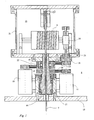
- a hollow shaft 14 is connected via a conventionally designed rotatable support 17 with the upper cover of the lock chamber 18 of the crystal pulling system.
- the hollow shaft 14 is driven via a toothed belt 20 by a motor designated as a rotary motor 11, for example a speed-controlled servomotor.
- the hollow shaft 14 of the cable winding mechanism 15 is fixed, which is installed in a vacuum-tight, cylindrical housing 21.
- the hollow shaft 14 is coaxially surrounded by a likewise designed as a hollow shaft gear 16, with respect to the first-mentioned hollow shaft 14th is rotatably mounted.
- the double gear 16 is driven by a toothed belt 22 by a motor called a pulling motor 10, for example a variable speed servomotor.
- the double gear 16 transmits, via a toothed belt 23, mechanical energy to the cable winding mechanism 15, when it is moved by the pulling motor 10 at a certain speed, which deviates from the rotational speed of the hollow shaft 14.
- the cable winding mechanism 15 consists of a horizontally arranged cable drum 9, which is driven via a worm gear 24 by an auxiliary shaft 25, which in turn is driven by the toothed belt 23 of the double gear 16.
- the auxiliary shaft 25 can be guided through a vacuum-tight shaft bushing 26, for example by means of a radial shaft sealing ring or a ferrofluidic seal in the vacuum-tight, cylindrical housing 21.
- a vacuum-tight shaft bushing 26 for example by means of a radial shaft sealing ring or a ferrofluidic seal in the vacuum-tight, cylindrical housing 21.
- the toothed belt 20, 22, 23 can each be used also a gear transmission.
- the pulling cable 7 running from the cable drum 9 can be guided via a deflection roller 27 in order to achieve an improved centering and adjustability of the entry point of the pulling cable 7 into the crystal pulling system.
- the cable drum 9 can also be arranged vertically and even be driven by a toothed belt or a gear drive, in which case at least one guide roller is required to redirect the drawing rope 7 running in a horizontal plane from the cable drum 9 in the vertical direction.
- the engine speeds of the motors 10, 11 and the translations of the timing belt 20, 22 are taken into account.
- the lifting or lowering speed of the pulling cable 7 from the engine speeds of the two motors 10, 11 clearly calculated.
- the required engine speed of the pulling motor 10 can be calculated in order to arrive at the desired lifting or lowering speed of the pulling cable 7.
- the axes of the motors 10, 11 can be connected to one incremental encoder each.
- the system controller determines the angles traveled by the motor shafts at fixed time intervals and calculates the distance traveled by the seed crystal holder 6 therefrom.
- a reference travel to find a vertical reference position must then be performed with the cable stroke, the cable stroke being activated by the seed crystal holder 6 until a reference switch, for example a light barrier, is reached.
Landscapes
- Chemical & Material Sciences (AREA)
- Engineering & Computer Science (AREA)
- Crystallography & Structural Chemistry (AREA)
- Materials Engineering (AREA)
- Metallurgy (AREA)
- Organic Chemistry (AREA)
- Crystals, And After-Treatments Of Crystals (AREA)
- Lubricants (AREA)
Claims (13)
- Installation de tirage de cristaux avec une tête rotative pour câble qui est rotative autour d'un axe de rotation vertical au moyen d'un moteur de rotation monté fixe sur l'installation de tirage de cristaux, un mécanisme d'enroulement de câble entraîné par un moteur de tirage via une transmission étant installé dans la tête rotative pour câble avec lequel un câble de tirage suspendu dans l'axe vertical peut être déplacé verticalement, caractérisée en ce que le moteur de tirage (10) est monté également fixe sur l'installation de tirage de cristaux et en ce que la transmission entre le moteur de tirage (10) et le mécanisme d'enroulement de câble (15) présente un élément de transmission dont l'axe de rotation coincide avec l'axe de rotation vertical de la tête rotative pour câble (8).
- Installation de tirage de cristaux selon la revendication 1, caractérisée en ce qu'une commande d'installation est prévue qui règle le mouvement d'entraînement du moteur de tirage (10) de telle sorte que l'entraînement du mécanisme d'enroulement de câble (15) induit par une rotation de la tête rotative pour câble (8) et le mouvement verticale enchaîné de ce fait du câble de tirage (7) sont compensés et qu'une vitesse de levage communiquée à la commande d'installation du câble de tirage (7) est atteinte.
- Installation de tirage de cristaux selon la revendication 2, caractérisée en ce que les deux moteurs (10, 11) sont chacun couplés à un capteur incrémentiel dont les signaux sont mis à la disposition de la commande d'installation.
- Installation de tirage de cristaux selon une quelconque des revendications précédentes, caractérisée en ce que le câble de tirage (7) est guidé à travers un arbre creux (14) qui porte la tête rotative pour câble (8) et en ce que l'élément de transmission est monté pivotable sur l'arbre creux (14).
- Installation de tirage de cristaux selon une quelconque des revendications précédentes, caractérisée en ce que l'élément de transmission est un engrenage double (16) avec deux dentures superposées, l'engrenage inférieur étant couplé avec l'arbre de sortie (14) du moteur de tirage et l'engrenage supérieur étant couplé avec un arbre intermédiaire (25) du mécanisme d'enroulement de câble (15).
- Installation de tirage de cristaux selon la revendication 5, caractérisée en ce que la liaison d'entraînement de l'engrenage avec l'arbre de sortie (14) ou avec l'arbre d'entraînement présente à chaque fois une courroie dentée (20).
- Installation de tirage de cristaux selon une quelconque des revendications 2 à 6, caractérisée en ce qu'au moins un capteur de position est prévu pour déterminer la course du câble.
- Installation de tirage de cristaux selon la revendication 7, caractérisée en ce qu'à l'extrémité du câble de tirage (7) est prévu un support, en particulier un support de germe cristallin et en ce que le capteur de position est constitué comme capteur de fin de course de position dans la position maximale du support.
- Installation de tirage de cristaux selon la revendication 8, caractérisée en ce que la commande d'installation est disposée de telle sorte qu'en partant de la position extrême du support, dont l'obtention est définie au moyen du capteur de fin de course de position, et des signaux de capteurs incrémentiels, il est possible de définir la course à chaque fois actuelle du support.
- Tête rotative pour câble pour une installation de tirage de cristaux qui est rotative autour d'un axe de rotation vertical au moyen d'un moteur de rotation monté fixe sur l'installation de tirage de cristaux, un mécanisme d'enroulement de câble entraîné par un moteur de tirage via une transmission étant installé dans la tête rotative pour câble avec lequel un câble de tirage suspendu dans l'axe vertical peut être déplacé verticalement, caractérisée en ce que la transmission entre le moteur de tirage (10) et le mécanisme d'enroulement de câble (15) présente un élément de transmission dont l'axe de rotation coïncide avec l'axe de rotation vertical de la tête rotative pour câble (8) de sorte qu'il est possible de monter fixement le moteur de tirage (10) sur l'installation de tirage de cristaux.
- Tête rotative pour câble selon la revendication 10, caractérisée en ce que le câble de tirage (7) est guidé à travers un arbre creux (14) qui porte la tête rotative pour câble (8) et en ce que l'élément de transmission est monté pivotable sur l'arbre creux (14).
- Tête rotative pour câble selon la revendication 10 ou 11, caractérisée en ce que l'élément de transmission est un engrenage double (16) avec deux dentures superposées, l'engrenage inférieur étant couplé avec l'arbre de sortie (14) du moteur de tirage et l'engrenage supérieur avec un arbre intermédiaire (25) du mécanisme d'enroulement de câble (15).
- Tête rotative pour câble selon la revendication 12, caractérisée en ce que la liaison d'entraînement de l'engrenage avec l'arbre de sortie (14) ou avec l'arbre d'entraînement présente à chaque fois une courroie dentée (20).
Priority Applications (1)
| Application Number | Priority Date | Filing Date | Title |
|---|---|---|---|
| PL05743152T PL1730331T3 (pl) | 2004-03-11 | 2005-03-11 | Urządzenie do wyciągania monokryształów z głowicą obrotu linki i głowica obrotu linki dla urządzenia do wyciągania monokryształów |
Applications Claiming Priority (2)
| Application Number | Priority Date | Filing Date | Title |
|---|---|---|---|
| DE102004011901A DE102004011901A1 (de) | 2004-03-11 | 2004-03-11 | Seildrehkopf für eine Kristallziehanlage |
| PCT/DE2005/000461 WO2005087985A1 (fr) | 2004-03-11 | 2005-03-11 | Tete rotative pour cable conçue pour une installation de tirage de cristaux |
Publications (2)
| Publication Number | Publication Date |
|---|---|
| EP1730331A1 EP1730331A1 (fr) | 2006-12-13 |
| EP1730331B1 true EP1730331B1 (fr) | 2013-05-22 |
Family
ID=34967885
Family Applications (1)
| Application Number | Title | Priority Date | Filing Date |
|---|---|---|---|
| EP05743152.0A Expired - Lifetime EP1730331B1 (fr) | 2004-03-11 | 2005-03-11 | Installation de tirage de cristeaux avec un tete rotative pour cable et tete rotative de cable concue pour une installation de tirage de cristaux |
Country Status (7)
| Country | Link |
|---|---|
| US (1) | US7662231B2 (fr) |
| EP (1) | EP1730331B1 (fr) |
| KR (1) | KR100831609B1 (fr) |
| DE (1) | DE102004011901A1 (fr) |
| NO (1) | NO335846B1 (fr) |
| PL (1) | PL1730331T3 (fr) |
| WO (1) | WO2005087985A1 (fr) |
Families Citing this family (5)
| Publication number | Priority date | Publication date | Assignee | Title |
|---|---|---|---|---|
| KR101119188B1 (ko) * | 2009-12-15 | 2012-03-19 | 서동욱 | 곡선부 동력전달장치 |
| US8721786B2 (en) | 2010-09-08 | 2014-05-13 | Siemens Medical Solutions Usa, Inc. | Czochralski crystal growth process furnace that maintains constant melt line orientation and method of operation |
| US11255024B2 (en) * | 2019-06-18 | 2022-02-22 | Linton Crystal Technologies Corp. | Seed lifting and rotating system for use in crystal growth |
| US11891721B2 (en) | 2020-12-09 | 2024-02-06 | Linton Kayex Technology Co., Ltd | Spool-balanced seed lift |
| CN113758252B (zh) * | 2021-08-24 | 2024-07-02 | 上海汉虹精密机械有限公司 | 碳化硅炉专用坩埚升降旋转机构 |
Family Cites Families (9)
| Publication number | Priority date | Publication date | Assignee | Title |
|---|---|---|---|---|
| US4190630A (en) * | 1978-01-03 | 1980-02-26 | Vsesojuzny Nauchno-Isslekovatelsky Institut Monokristallov Stsintillyatsionnykh Materialov I Osobo Chistykh Khimicheskikh Veschestv | Apparatus for pulling single crystals from melt |
| DE3116916C2 (de) * | 1980-06-14 | 1984-08-23 | Leybold-Heraeus GmbH, 5000 Köln | Vorrichtung zum Ziehen eines Einkristalls aus einem Tiegel mittels eines aufwickelbaren Zugorgans |
| NL8102566A (nl) | 1980-06-14 | 1982-01-04 | Leybold Heraeus Gmbh & Co Kg | Inrichting voor het door middel van een opwikkelbaar trekorgaan uit een kroes trekken van een enkel kristal. |
| US4663128A (en) * | 1985-03-06 | 1987-05-05 | Ferrofluidics Corporation | Pulling head for a crystal growing furnace |
| DE3733562A1 (de) * | 1987-10-03 | 1989-04-20 | Leybold Ag | Vorrichtung zum ziehen eines einkristalls aus einem tiegel mittels eines aufwickelbaren ziehorgans |
| DE69017642T2 (de) | 1989-12-22 | 1995-07-06 | Shinetsu Handotai Kk | Vorrichtung zur Herstellung von Einkristallen nach dem Czochralski-Verfahren. |
| DE4329283C2 (de) | 1993-08-31 | 1997-02-13 | Leybold Ag | Drehkopf für Kristallziehanlagen für die Durchführung des Czochralski-Prozesses |
| DE19932026B4 (de) | 1999-07-09 | 2008-09-11 | Crystal Growing Systems Gmbh | Einrichtung zum Züchten von Kristallen mittels des Czochralski-Verfahrens, bei dem die Kristalle während des Züchtungsprozesses sowohl aus der Schmelze gezogen als auch um eine Achse gedreht werden |
| DE10007265B4 (de) * | 2000-02-17 | 2009-10-22 | Crystal Growing Systems Gmbh | Kristallziehanlage |
-
2004
- 2004-03-11 DE DE102004011901A patent/DE102004011901A1/de not_active Ceased
-
2005
- 2005-03-11 PL PL05743152T patent/PL1730331T3/pl unknown
- 2005-03-11 KR KR1020067021083A patent/KR100831609B1/ko not_active Expired - Lifetime
- 2005-03-11 EP EP05743152.0A patent/EP1730331B1/fr not_active Expired - Lifetime
- 2005-03-11 US US10/592,262 patent/US7662231B2/en not_active Expired - Lifetime
- 2005-03-11 WO PCT/DE2005/000461 patent/WO2005087985A1/fr not_active Ceased
-
2006
- 2006-09-08 NO NO20064067A patent/NO335846B1/no unknown
Also Published As
| Publication number | Publication date |
|---|---|
| PL1730331T3 (pl) | 2013-10-31 |
| KR20060120290A (ko) | 2006-11-24 |
| NO335846B1 (no) | 2015-03-02 |
| US20080000415A1 (en) | 2008-01-03 |
| DE102004011901A1 (de) | 2005-12-01 |
| US7662231B2 (en) | 2010-02-16 |
| NO20064067L (no) | 2006-10-10 |
| WO2005087985A1 (fr) | 2005-09-22 |
| KR100831609B1 (ko) | 2008-05-23 |
| EP1730331A1 (fr) | 2006-12-13 |
Similar Documents
| Publication | Publication Date | Title |
|---|---|---|
| DE69017642T2 (de) | Vorrichtung zur Herstellung von Einkristallen nach dem Czochralski-Verfahren. | |
| EP1730331B1 (fr) | Installation de tirage de cristeaux avec un tete rotative pour cable et tete rotative de cable concue pour une installation de tirage de cristaux | |
| US4367199A (en) | Apparatus having coilable pulling element for drawing a monocrystal from a crucible with adjustable speed | |
| DE69020962T2 (de) | Einkristallziehvorrichtung und Verfahren. | |
| DE69210642T2 (de) | Vorrichtung zum Ziehen von Einkristallen | |
| DE2833615C2 (de) | Vorrichtung zum tiegelfreien Zonenschmelzen | |
| DE4235495C2 (de) | Antriebsvorrichtung für einen Grundrahmen einer Stickmaschine | |
| DE4329283C2 (de) | Drehkopf für Kristallziehanlagen für die Durchführung des Czochralski-Prozesses | |
| EP0518297B1 (fr) | Dispositif d'excavation et procédé pour la commande de la vitesse d'avance d'un outil d'excavation | |
| DE3116916C2 (de) | Vorrichtung zum Ziehen eines Einkristalls aus einem Tiegel mittels eines aufwickelbaren Zugorgans | |
| KR20220039596A (ko) | 액티브 밸런싱 씨드 리프트 | |
| CN107742861A (zh) | 一种具有在线监控功能的桥架 | |
| DE2741204A1 (de) | Umladesystem zum umladen von brennstoffelementen eines kernreaktors | |
| EP0498318A2 (fr) | Dispositif de réglage d'une hauteur de remplissage | |
| CN212450097U (zh) | 盘状丝材的支撑架 | |
| DE2757772A1 (de) | Vorrichtung zum zonenschmelzen von polykristallinen halbleiterstaeben | |
| DE102004041736A1 (de) | Maschine zur kontinuierlichen Herstellung von Bewehrungskörben, besonders mit nichtkreisförmigem Querschnitt | |
| DE972100C (de) | Elektrischer Reduktions- oder Schmelzofen | |
| DE69016317T2 (de) | Einkristallziehungsapparat. | |
| DE19932026B4 (de) | Einrichtung zum Züchten von Kristallen mittels des Czochralski-Verfahrens, bei dem die Kristalle während des Züchtungsprozesses sowohl aus der Schmelze gezogen als auch um eine Achse gedreht werden | |
| DE2848928C2 (de) | Gerät zum Ausbessern der Zustellung von Schmelzöfen, Gießpfannen o.dgl. | |
| EP0233950A1 (fr) | Dispositif permettant la croissance de monocristaux d'oxydes metalliques refractaires a partir de la coulee | |
| CN221275838U (zh) | 一种整体式被动锥齿轮自动化压淬结构 | |
| EP0867535A2 (fr) | Tête rotative dans un appareillage de tirage de cristaux selon la méthode de Czochralski | |
| DE2634256A1 (de) | Einrichtung zur gruppenweisen zuechtung von einkristallen aus der schmelze |
Legal Events
| Date | Code | Title | Description |
|---|---|---|---|
| PUAI | Public reference made under article 153(3) epc to a published international application that has entered the european phase |
Free format text: ORIGINAL CODE: 0009012 |
|
| 17P | Request for examination filed |
Effective date: 20060902 |
|
| AK | Designated contracting states |
Kind code of ref document: A1 Designated state(s): AT BE BG CH CY CZ DE DK EE ES FI FR GB GR HU IE IS IT LI LT LU MC NL PL PT RO SE SI SK TR |
|
| DAX | Request for extension of the european patent (deleted) | ||
| RAP1 | Party data changed (applicant data changed or rights of an application transferred) |
Owner name: PVA TEPLA AG |
|
| 17Q | First examination report despatched |
Effective date: 20100813 |
|
| GRAP | Despatch of communication of intention to grant a patent |
Free format text: ORIGINAL CODE: EPIDOSNIGR1 |
|
| GRAS | Grant fee paid |
Free format text: ORIGINAL CODE: EPIDOSNIGR3 |
|
| GRAA | (expected) grant |
Free format text: ORIGINAL CODE: 0009210 |
|
| AK | Designated contracting states |
Kind code of ref document: B1 Designated state(s): AT BE BG CH CY CZ DE DK EE ES FI FR GB GR HU IE IS IT LI LT LU MC NL PL PT RO SE SI SK TR |
|
| REG | Reference to a national code |
Ref country code: GB Ref legal event code: FG4D Free format text: NOT ENGLISH |
|
| REG | Reference to a national code |
Ref country code: CH Ref legal event code: EP |
|
| REG | Reference to a national code |
Ref country code: AT Ref legal event code: REF Ref document number: 613300 Country of ref document: AT Kind code of ref document: T Effective date: 20130615 |
|
| REG | Reference to a national code |
Ref country code: IE Ref legal event code: FG4D Free format text: LANGUAGE OF EP DOCUMENT: GERMAN |
|
| REG | Reference to a national code |
Ref country code: DE Ref legal event code: R096 Ref document number: 502005013725 Country of ref document: DE Effective date: 20130725 |
|
| REG | Reference to a national code |
Ref country code: LT Ref legal event code: MG4D |
|
| PG25 | Lapsed in a contracting state [announced via postgrant information from national office to epo] |
Ref country code: SI Free format text: LAPSE BECAUSE OF FAILURE TO SUBMIT A TRANSLATION OF THE DESCRIPTION OR TO PAY THE FEE WITHIN THE PRESCRIBED TIME-LIMIT Effective date: 20130522 Ref country code: IS Free format text: LAPSE BECAUSE OF FAILURE TO SUBMIT A TRANSLATION OF THE DESCRIPTION OR TO PAY THE FEE WITHIN THE PRESCRIBED TIME-LIMIT Effective date: 20130922 Ref country code: GR Free format text: LAPSE BECAUSE OF FAILURE TO SUBMIT A TRANSLATION OF THE DESCRIPTION OR TO PAY THE FEE WITHIN THE PRESCRIBED TIME-LIMIT Effective date: 20130823 Ref country code: ES Free format text: LAPSE BECAUSE OF FAILURE TO SUBMIT A TRANSLATION OF THE DESCRIPTION OR TO PAY THE FEE WITHIN THE PRESCRIBED TIME-LIMIT Effective date: 20130902 Ref country code: PT Free format text: LAPSE BECAUSE OF FAILURE TO SUBMIT A TRANSLATION OF THE DESCRIPTION OR TO PAY THE FEE WITHIN THE PRESCRIBED TIME-LIMIT Effective date: 20130923 Ref country code: LT Free format text: LAPSE BECAUSE OF FAILURE TO SUBMIT A TRANSLATION OF THE DESCRIPTION OR TO PAY THE FEE WITHIN THE PRESCRIBED TIME-LIMIT Effective date: 20130522 Ref country code: SE Free format text: LAPSE BECAUSE OF FAILURE TO SUBMIT A TRANSLATION OF THE DESCRIPTION OR TO PAY THE FEE WITHIN THE PRESCRIBED TIME-LIMIT Effective date: 20130522 |
|
| REG | Reference to a national code |
Ref country code: PL Ref legal event code: T3 |
|
| REG | Reference to a national code |
Ref country code: NL Ref legal event code: VDEP Effective date: 20130522 |
|
| PG25 | Lapsed in a contracting state [announced via postgrant information from national office to epo] |
Ref country code: BG Free format text: LAPSE BECAUSE OF FAILURE TO SUBMIT A TRANSLATION OF THE DESCRIPTION OR TO PAY THE FEE WITHIN THE PRESCRIBED TIME-LIMIT Effective date: 20130822 |
|
| PG25 | Lapsed in a contracting state [announced via postgrant information from national office to epo] |
Ref country code: SK Free format text: LAPSE BECAUSE OF FAILURE TO SUBMIT A TRANSLATION OF THE DESCRIPTION OR TO PAY THE FEE WITHIN THE PRESCRIBED TIME-LIMIT Effective date: 20130522 Ref country code: DK Free format text: LAPSE BECAUSE OF FAILURE TO SUBMIT A TRANSLATION OF THE DESCRIPTION OR TO PAY THE FEE WITHIN THE PRESCRIBED TIME-LIMIT Effective date: 20130522 Ref country code: EE Free format text: LAPSE BECAUSE OF FAILURE TO SUBMIT A TRANSLATION OF THE DESCRIPTION OR TO PAY THE FEE WITHIN THE PRESCRIBED TIME-LIMIT Effective date: 20130522 Ref country code: CZ Free format text: LAPSE BECAUSE OF FAILURE TO SUBMIT A TRANSLATION OF THE DESCRIPTION OR TO PAY THE FEE WITHIN THE PRESCRIBED TIME-LIMIT Effective date: 20130522 |
|
| PG25 | Lapsed in a contracting state [announced via postgrant information from national office to epo] |
Ref country code: RO Free format text: LAPSE BECAUSE OF FAILURE TO SUBMIT A TRANSLATION OF THE DESCRIPTION OR TO PAY THE FEE WITHIN THE PRESCRIBED TIME-LIMIT Effective date: 20130522 Ref country code: NL Free format text: LAPSE BECAUSE OF FAILURE TO SUBMIT A TRANSLATION OF THE DESCRIPTION OR TO PAY THE FEE WITHIN THE PRESCRIBED TIME-LIMIT Effective date: 20130522 |
|
| PLBE | No opposition filed within time limit |
Free format text: ORIGINAL CODE: 0009261 |
|
| STAA | Information on the status of an ep patent application or granted ep patent |
Free format text: STATUS: NO OPPOSITION FILED WITHIN TIME LIMIT |
|
| 26N | No opposition filed |
Effective date: 20140225 |
|
| REG | Reference to a national code |
Ref country code: DE Ref legal event code: R097 Ref document number: 502005013725 Country of ref document: DE Effective date: 20140225 |
|
| PG25 | Lapsed in a contracting state [announced via postgrant information from national office to epo] |
Ref country code: LU Free format text: LAPSE BECAUSE OF FAILURE TO SUBMIT A TRANSLATION OF THE DESCRIPTION OR TO PAY THE FEE WITHIN THE PRESCRIBED TIME-LIMIT Effective date: 20140311 |
|
| REG | Reference to a national code |
Ref country code: CH Ref legal event code: PL |
|
| GBPC | Gb: european patent ceased through non-payment of renewal fee |
Effective date: 20140311 |
|
| REG | Reference to a national code |
Ref country code: FR Ref legal event code: ST Effective date: 20141128 |
|
| REG | Reference to a national code |
Ref country code: IE Ref legal event code: MM4A |
|
| PG25 | Lapsed in a contracting state [announced via postgrant information from national office to epo] |
Ref country code: FR Free format text: LAPSE BECAUSE OF NON-PAYMENT OF DUE FEES Effective date: 20140331 Ref country code: LI Free format text: LAPSE BECAUSE OF NON-PAYMENT OF DUE FEES Effective date: 20140331 Ref country code: GB Free format text: LAPSE BECAUSE OF NON-PAYMENT OF DUE FEES Effective date: 20140311 Ref country code: CH Free format text: LAPSE BECAUSE OF NON-PAYMENT OF DUE FEES Effective date: 20140331 Ref country code: IE Free format text: LAPSE BECAUSE OF NON-PAYMENT OF DUE FEES Effective date: 20140311 |
|
| REG | Reference to a national code |
Ref country code: AT Ref legal event code: MM01 Ref document number: 613300 Country of ref document: AT Kind code of ref document: T Effective date: 20140311 |
|
| PG25 | Lapsed in a contracting state [announced via postgrant information from national office to epo] |
Ref country code: AT Free format text: LAPSE BECAUSE OF NON-PAYMENT OF DUE FEES Effective date: 20140311 |
|
| PG25 | Lapsed in a contracting state [announced via postgrant information from national office to epo] |
Ref country code: MC Free format text: LAPSE BECAUSE OF FAILURE TO SUBMIT A TRANSLATION OF THE DESCRIPTION OR TO PAY THE FEE WITHIN THE PRESCRIBED TIME-LIMIT Effective date: 20130522 |
|
| PG25 | Lapsed in a contracting state [announced via postgrant information from national office to epo] |
Ref country code: CY Free format text: LAPSE BECAUSE OF FAILURE TO SUBMIT A TRANSLATION OF THE DESCRIPTION OR TO PAY THE FEE WITHIN THE PRESCRIBED TIME-LIMIT Effective date: 20130522 |
|
| PG25 | Lapsed in a contracting state [announced via postgrant information from national office to epo] |
Ref country code: HU Free format text: LAPSE BECAUSE OF FAILURE TO SUBMIT A TRANSLATION OF THE DESCRIPTION OR TO PAY THE FEE WITHIN THE PRESCRIBED TIME-LIMIT; INVALID AB INITIO Effective date: 20050311 Ref country code: TR Free format text: LAPSE BECAUSE OF FAILURE TO SUBMIT A TRANSLATION OF THE DESCRIPTION OR TO PAY THE FEE WITHIN THE PRESCRIBED TIME-LIMIT Effective date: 20130522 |
|
| PG25 | Lapsed in a contracting state [announced via postgrant information from national office to epo] |
Ref country code: BE Free format text: LAPSE BECAUSE OF NON-PAYMENT OF DUE FEES Effective date: 20140331 |
|
| REG | Reference to a national code |
Ref country code: DE Ref legal event code: R082 Ref document number: 502005013725 Country of ref document: DE Representative=s name: RAUCH, UDO, DIPL.-PHYS. DR. PHIL. NAT., DE |
|
| PGFP | Annual fee paid to national office [announced via postgrant information from national office to epo] |
Ref country code: FI Payment date: 20240320 Year of fee payment: 20 Ref country code: DE Payment date: 20240215 Year of fee payment: 20 |
|
| PGFP | Annual fee paid to national office [announced via postgrant information from national office to epo] |
Ref country code: PL Payment date: 20240220 Year of fee payment: 20 Ref country code: IT Payment date: 20240322 Year of fee payment: 20 |
|
| REG | Reference to a national code |
Ref country code: DE Ref legal event code: R071 Ref document number: 502005013725 Country of ref document: DE |