EP1729389A1 - Dispositif de guidage de conduites flexibles électriques ou à fluide - Google Patents
Dispositif de guidage de conduites flexibles électriques ou à fluide Download PDFInfo
- Publication number
- EP1729389A1 EP1729389A1 EP06010131A EP06010131A EP1729389A1 EP 1729389 A1 EP1729389 A1 EP 1729389A1 EP 06010131 A EP06010131 A EP 06010131A EP 06010131 A EP06010131 A EP 06010131A EP 1729389 A1 EP1729389 A1 EP 1729389A1
- Authority
- EP
- European Patent Office
- Prior art keywords
- cable guide
- line
- guide device
- cable
- fastening
- Prior art date
- Legal status (The legal status is an assumption and is not a legal conclusion. Google has not performed a legal analysis and makes no representation as to the accuracy of the status listed.)
- Withdrawn
Links
Images


Classifications
-
- H—ELECTRICITY
- H02—GENERATION; CONVERSION OR DISTRIBUTION OF ELECTRIC POWER
- H02G—INSTALLATION OF ELECTRIC CABLES OR LINES, OR OF COMBINED OPTICAL AND ELECTRIC CABLES OR LINES
- H02G11/00—Arrangements of electric cables or lines between relatively-movable parts
- H02G11/006—Arrangements of electric cables or lines between relatively-movable parts using extensible carrier for the cable, e.g. self-coiling spring
-
- F—MECHANICAL ENGINEERING; LIGHTING; HEATING; WEAPONS; BLASTING
- F16—ENGINEERING ELEMENTS AND UNITS; GENERAL MEASURES FOR PRODUCING AND MAINTAINING EFFECTIVE FUNCTIONING OF MACHINES OR INSTALLATIONS; THERMAL INSULATION IN GENERAL
- F16L—PIPES; JOINTS OR FITTINGS FOR PIPES; SUPPORTS FOR PIPES, CABLES OR PROTECTIVE TUBING; MEANS FOR THERMAL INSULATION IN GENERAL
- F16L3/00—Supports for pipes, cables or protective tubing, e.g. hangers, holders, clamps, cleats, clips, brackets
- F16L3/01—Supports for pipes, cables or protective tubing, e.g. hangers, holders, clamps, cleats, clips, brackets for supporting or guiding the pipes, cables or protective tubing, between relatively movable points, e.g. movable channels
- F16L3/015—Supports for pipes, cables or protective tubing, e.g. hangers, holders, clamps, cleats, clips, brackets for supporting or guiding the pipes, cables or protective tubing, between relatively movable points, e.g. movable channels using articulated- or supple-guiding elements
-
- H—ELECTRICITY
- H02—GENERATION; CONVERSION OR DISTRIBUTION OF ELECTRIC POWER
- H02G—INSTALLATION OF ELECTRIC CABLES OR LINES, OR OF COMBINED OPTICAL AND ELECTRIC CABLES OR LINES
- H02G11/00—Arrangements of electric cables or lines between relatively-movable parts
Definitions
- the invention relates to a cable guide device for bendable electrical and / or fluidic lines, with at least one variable longitudinal course having cable guide strand, which is traversed in the longitudinal direction of at least one line-receiving channel.
- Machinery and mechanical systems are often equipped with linearly displacing components, which are to be supplied with electrical energy and / or fluidic media, the latter, for example, compressed air or hydraulic oil.
- electrical energy and / or fluidic media for example, compressed air or hydraulic oil.
- bendable electrical and / or fluidic lines are used, which can join the movement of the component to be supplied.
- the fluidic lines are, for example, bendable compressed air or hydraulic hoses, while the electrical lines are generally designed as single or multi-core bendable cables.
- the machines or installations may be equipped with a line guiding device which has a line guide line surrounding the lines in a protective manner, so that he is able to adapt his current shape to the relative position of the associated components of the machine or plant.
- Known wire guide device includes a chain-like cable management strand, which consists of a plurality of hingedly interconnected strand elements, so that variable course changes are possible within a plane.
- the known cable guide device also includes a rail-like guide device on which the cable guide strand can roll off.
- Within the cable management strand is a continuous line-receiving channel in which the lines to be led are housed together.
- a disadvantage of the known cable guide device are the relatively high production costs, which are caused, inter alia, by the cable guide strand consisting of many individual parts. After the production of the individual parts, these must be assembled consuming.
- the cable guide strand is formed of a material with rubber-elastic properties existing flexible profile part distributed over its circumference several each having a line receiving channel forming undercut longitudinal grooves with aufweitbarem by elastic deformation of the profile part Nuthals.
- the line guide strand can be very easily produced, for example by extrusion, as a one-piece profile part, wherein different strand lengths can be obtained by cutting from meter goods.
- line receiving channels formed in the profile part trained longitudinal grooves, which can be provided in an appropriate, if necessary specifically tailored to the particular application distribution and number.
- the feasibility of multiple independent line-receiving channels within one and the same profile part also allows, if necessary, to move several lines separately, which for example opens the possibility to separate fluidic and electrical lines from each other and thus in particular the risk of damage to an electrical Reduce line attributable short circuits.
- the flexible profile part has a relatively low specific weight by itself, in addition, in connection with the inherent inherent stability inherent in many cases, it will be possible to dispense with a separate external guide device. As a result, the costs to be incurred are reduced by a further not inconsiderable factor.
- Another advantage is the ease of assembly and disassembly of the leading lines. These do not have to be laboriously threaded through a channel which is closed all around, but can be easily pressed from the side through the elastically expandable groove neck of the relevant longitudinal groove.
- the wiring harness is made of a soft foam material.
- a realization of so-called sponge rubber has been found.
- the insertion of a line into the line-receiving channel is particularly simple if the Nuthals of the respective longitudinal groove has a widening to the outer surface of the line guide strand insertion section.
- serving for routing longitudinal grooves may be provided on only one or more of the four outer surfaces of the profile part.
- the cable guide device expediently contains one or more fastening elements.
- the fastener holds on the one hand the line guide strand and can be fastened to the other directly or indirectly to a supporting structure, which is usually a part of one of two relatively movable components.
- a plurality of fasteners are present, which engage at longitudinally spaced locations on the same line guide strand.
- two fastening elements can be assigned to each line guide strand be, each serving to fix one of the two end portions of the wiring harness.
- the fastening element which is preferably made of plastic material in a cost-effective manner, is expediently designed in the manner of a frame and surrounds the line guide strand to be fixed at the intended fastening point.
- the inner cross section of the fastening element and the outer cross section of the cable guide strand are suitably matched to one another such that the cable guide strand is enclosed under at least low prestressing and is thereby reliably held fast.
- the mounting of a fastener on the wiring harness is simplified when the fastener has a cross-sectionally U-shaped base and one of the base opening associated lid. With the cover removed, the wiring harness can be placed in the base. By subsequently closing the lid, the frame structure enclosing the cable guide strand results.
- the lid is pivotally mounted on the base and can be pivoted to open and close the fastener relative to the base.
- the bearing can be realized in particular by means of a one-piece solid-body joint.
- the fastening measures are simplified, in particular, when the line guide device has a plurality of line guide strands.
- the cable guide strand according to the invention is not only suitable for dynamic applications, but also for such a static nature. Thus, even if the cable guide strand during its use keeps its shape constant, its flexibility facilitates the production and laying work.
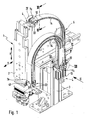
- Figures 1 and 2 show a machine device 1 operated using a fluidic medium and electrical energy in an exemplary embodiment.
- This device 1 is used for handling objects and in particular for converting such objects between two positions during a manufacturing or assembly process.
- the device 1 has inter alia a first device component 2, which is movable relative to a second device component 3 during operation.
- the first device component 2 can be displaced in an x-y plane relative to the second device component 3.
- the first device component 2 is supplied via electrical and fluidic lines 4 with electrical energy and a fluidic pressure medium, the latter in particular compressed air.
- These lines 4 are indicated in the individual drawing figures partially only dash-dotted lines.
- electrical lines 4a are concerned, they are designed in particular in the form of single or multi-core cables.
- the fluidic lines 4b are formed by tubes. In all cases, the lines 4 are flexible and easily bendable.
- the lines 4 extend between the two relative to each other movable device components 2, 3. Thus, this adjusts an orderly line routing and the lines 4 are particularly protected against damage from moving parts, the lines 4 are laid in one or more glovess Equipmentsstr brieflyen 5, the Part of a generally designated by reference numeral 6 cable guide means are equipped with the machine device 1.
- One and the same machine device 1 can have only one or several cable guide strands 5 at a time.
- Each line strand 5 is fixed at two spaced locations - hereinafter referred to as the first and second attachment point 7a, 7b - fixed to each one of the two device components 2, 3. These fastening points 7a, 7b are located in particular at the mutually opposite end sections of a respective line guide strand 5.
- the cable guide strands 5 are each formed in one piece by a flexible profile part consisting of material with rubber-elastic properties. Due to its flexibility, the cable guide strand 5 can be easily bent, so that changes its longitudinal course. Such a variation of the longitudinal course is automatically established during the relative movement between the two device components 2, 3, because in this case also the relative position between the first and second attachment points 7a, 7b of a respective line guide strand 5 changes.
- the cable guide strands 5 are laid so that they have a linear and a curved course in sections.
- the length of the linear sections changes with a simultaneous change in position of the curved section. Due to the high flexibility, the change in shape takes place within the framework of a harmonious sequence of movements.
- the lines 4 extend in line receiving channels 8, of which each line guide strand 5 has a plurality and the enforce the relevant line guide strand 5 parallel to its longitudinal axis in the longitudinal direction, where they open at the two opposite end faces of a respective line guide strand 5.
- the lines 4 extending in the line receiving channels 8 pass out of the line receiving channels 8 in the region of the frontal side openings and run from there to associated connection points of the relevant device components 2, 3, not shown. Due to their flexibility, the lines 4 can change their shape the elastic cable guide strands 5 easily join.
- the line receiving channels 8 are formed by undercut longitudinal grooves 14 which are distributed over the circumference of a respective line guide strand 5 formed in this. More specifically, in the embodiment, the respective line receiving channel 8 is formed by the relative to the associated Nuthals 15 deeper in the line guide strand 5 inner portion 16 of the respective longitudinal groove 14 whose diameter is greater than the width of the Nuthalses 15 at its narrowest point.
- the transverse dimensions of the arranged in the line receiving channels 8 lines 4 are greater than the width of the associated Nuthalses 15.
- the insertion into a line-receiving channel 8 is done by the Nuthals 15 therethrough, which is widened due to elastic deformation of the profile part material for a short time.
- a line 4 can be easily withdrawn sideways if necessary through the Nuthals 15 from a line-receiving channel 8.
- the inner portions 16 of the longitudinal grooves 14 are also contoured circular in the embodiment. It is considered ideal if in each line-receiving channel 8 only a single line 4 extends, wherein the cross section of the inner portion 16 is tuned to the line cross-section, that the inner portion 16 with its wall - apart from the condition caused by the Nuthals 15 gap - Rests all around the outer circumference of the contained line 4.
- the cross-sectional dimensions can in particular be chosen so that the inserted line 4 is biased by the line guide strand 5 forming profile part is biased.
- the Nuthälse 15 each with a widening insertion section 17 to the outer surface of the line guide strand 5.
- the insertion section 17 may be designed to taper in the direction of the inner section 16 in the manner of a funnel.
- the profile part can be produced very inexpensively by extruding rubber or plastic material.
- a production in endless goods or by the meter may be provided, wherein the resultant strand material is then cut to the desired strand length from case to case.
- the cable guide strand 5 forming profile part is particularly suitable for foam. It is expedient to use a flexible foam material, in particular a flexible polyurethane foam.
- the cable guide strands 5 made of sponge rubber.
- the distribution of the longitudinal grooves 14 along the circumference of the line guide strand 5 is based on the respective needs and takes into account in particular the cross-sectional dimensions of the required line receiving channels 8. It has proved to be particularly useful if the profile guide 5 forming profile part as in the embodiment has a rectangular cross-section wherein one or more longitudinal grooves 14 may then be formed in a plurality of the resulting four outer surfaces of the profile part.
- the present in the embodiment rectangular profiling results in two opposing large-area outer surfaces 18a and in two narrow outer surfaces 18b.
- a longitudinal groove 14 per narrow outer surface 18b, in particular in the center of the width, the inner portion 16 is also formed relatively small in adaptation to the usually relatively small diameter of electrical lines 4b.
- the central axes of all inner sections 16 may extend in a profile part plane parallel to the large-area outer surfaces 18a.
- line-receiving channels 8 are considered particularly useful for many applications, because it allows, for example, summarize the meaningful for the operation and control of a fluid-operated drive lines in a common wiring harness 5. It is understood, however, that other configurations are possible.
- the cable guide strands 5 are expediently provided as a linear strand material, which can be reversibly bent into the desired shape with elastic deformation for the respective application.
- each line guide strand 5 is equipped at each of its two attachment points 7a, 7b with such a fastener 2, on the other hand, directly or with the interposition of adapter means 43 to the acting as a support structure associated device component 2, 3 is attached. Consequently, in the exemplary embodiment, a plurality of fastening elements 22 engage fastening points 7a, 7b spaced apart in the longitudinal direction on each line guide strand 5.
- the fastening elements 22 are preferably designed like a frame. Its frame contour corresponds to the outer contour of the cable guide device 6 and is therefore also substantially rectangular.
- the cable guide strand 5 is enclosed at its attachment points 7, 8 of the there placed frame-like fastener 2 around.
- the fastener 5 passing through the longitudinal section of the wiring harness 5 is expediently acted upon by the fastener 22 with a certain radial bias, so that there is a frictional connection, through which a fixed in the longitudinal direction of the wiring harness 5 fixed connection between the wiring harness 5 and the respective fastener 22nd established.
- the fastening element 22 has a clamping passage 24 defined by the frame structure, which is penetrated by the line guide strand 5.
- the fastener 22 has two opposing large-scale walls, which are referred to better distinction as upper and lower walls 25a, 25b, and two perpendicular thereto narrow side walls 26a, 26b.
- the limited by these four walls terminal passage 24 has a rectangular cross-sectional contour that is slightly smaller than the outer cross section of the line guide strand 5, so that its arranged in the terminal passage 24 longitudinal section is biased by the four aforementioned walls under bias.
- the lower wall 25b with the two narrow side walls 26a, 26b forms a one-piece, in Cross-section U-shaped base 27 with the base wall 28 pointing away from the bottom wall 25a.
- the top wall 25a represents a cover 29 closing the base opening 28 and thereby completing the frame structure.
- This cover 29 is integrally formed on one of its longitudinal sides to form a solid-state hinge 3.3 connected there narrow side wall 26a.
- the solid-state joint 33 is defined by a material web which is reduced in its material thickness relative to the neighboring regions, by means of which a pivot axis parallel to the longitudinal axis 34 of the fastening element 22 is provided, about which the cover 29 is pivotable relative to the base 27 according to double arrow 32, after the base opening 28 Choice to close or release.
- dash-dotted lines at 29a an occupied during the pivoting operation of the lid intermediate position is indicated.
- the lid 29 is pivoted open to release the base opening 28, then the line guide strand 5 inserted into the U-shaped base 27 and then the lid 29 closed again.
- the solid side joint 33 opposite narrow side wall 26b and the associated end portion of the lid 29 is provided with mutually complementary latching connection means 35. These consist in the embodiment of engaging behind hook-like projections.
- the latching connection can be easily solved by bending the cover-side latching means 35 carrying lid end portion.
- the locking connection itself adjusts automatically when the lid 29 is pressed into the closed position.
- the lid 29 is a relative to the base 27 separate component, which is temporarily removed for insertion of the line guide strand 5 of the base 27. Furthermore, there is the possibility in principle of providing a conventional hinge solution instead of the solid-state joint 33 in conjunction with a cover 29 which is separate relative to the base 27.
- fastening element 22 In order to fasten the fastening element 22 to the associated device component 2, 3 or another support structure, it is equipped with suitable fastening means 36.
- these comprise a plurality of fastening holes 37 passing through the lower wall 25b, which allow the insertion of fastening screws 38 indicated only in FIG. 3, by means of which the fastening element 22 can be screwed tightly to the support structure 2, 3.
- fastening means 36 may be provided on one of the narrow side walls 26 b, a longitudinal fastening groove 42 on the outside, which is used in conjunction with sliding blocks or an apparent from Figures 1 and 6 adapter 43 for direct or indirect attachment to the support structure 3.
- the fastener 22 can be securely supported on the associated support structure, equipped with the mounting holes 37 lower wall 25b in the direction of the longitudinal axis 34 expediently has a greater length than the adjoining narrow side walls 26a, 26b and acting as a lid 29 upper wall 25th In particular, it projects beyond only one axial side beyond these shorter walls.
- the line guide strand 5 may be provided on its outer surface with adhesive means 44 which can be seen by way of example from FIG. 7, wherein in particular at least one self-adhesive strip is possible.
- This has a protective film, which can be deducted to expose an adhesive surface.
- the adhesive strip may in particular extend over the entire length of the line guide strand 5. In the exemplary embodiment, it is located on that of the two large-area outer surfaces 18a, which has no longitudinal groove 14.
- the fastening elements 22 are expediently equipped with mutually complementary coupling means 45, 46, which make it possible to combine two or more fastening elements 22 to form an assembly.
- These coupling means 45, 46 consist in the exemplary embodiment of mutually complementary, continuously in the longitudinal direction 34 of the fasteners 22 extending groove-like depressions 45 and rib-like projections 46. These can be pushed together in the longitudinal direction, so that they engage behind the form-fitting manner.
- each of the fasteners 22 is provided with the mutually complementary coupling means 45, 46 and expediently an identical structure of all fasteners 22 is present, the fasteners 22 can be combined with each other, each provided on a fastener 22 coupling means 45 of a kind with the complementary thereto Coupling means 46 of the other fastening element 22 can be coupled.
- mutually complementary coupling means 45, 46 are provided on the outside of the two large upper and lower walls 25a, 25b, which enable a height-wise linking of a plurality of fastening elements 22, as indicated in FIG.
- complementary coupling means 45, 46 are present, which allow linking of a plurality of fastening elements 22 in their width direction, as indicated in Figure 8. As far as it is a groove-like depression in these coupling means, this can simultaneously take over the function of the above-described mounting groove 42.
- the coupling process of two fasteners 22 consists in pushing them together with simultaneous engagement of the complementary coupling means 45, 46.
- securing means are expediently provided which fix the successive fasteners 22 to each other so that they only with a certain application of force again can be deducted from each other.
- These securing means consist in the embodiment of integrally formed on the outer surface securing projections 47 which can engage positively in the other fastening element 22.
- the security surveys 47 engage expediently in the wall of the respective other fastening element 22 formed locking recesses or holes 48, the latter can be formed by the already mentioned mounting holes 37.
- the securing projections 47 and locking recesses 48 just described are located on the upper and lower walls 25 of the fastening element 22 and are thus effective in the case of fastening elements 22 stacked in the vertical direction.
- mutually complementary securing projections 47 'and locking recesses 48' may be present, which cause an axial position assurance in accordance with Figure 8 in the transverse direction attached to each other fasteners 22.
- the locking recess 48 ' may in this case be provided as an edge recess of the lid 29 (see FIG. 5), so that it can be brought into and out of engagement with the associated securing projection 47' by closing and opening the lid.
Applications Claiming Priority (1)
| Application Number | Priority Date | Filing Date | Title |
|---|---|---|---|
| DE200520008668 DE202005008668U1 (de) | 2005-06-03 | 2005-06-03 | Leitungsführungseinrichtung für biegbare elektrische oder fluidische Leitungen |
Publications (1)
| Publication Number | Publication Date |
|---|---|
| EP1729389A1 true EP1729389A1 (fr) | 2006-12-06 |
Family
ID=34854437
Family Applications (1)
| Application Number | Title | Priority Date | Filing Date |
|---|---|---|---|
| EP06010131A Withdrawn EP1729389A1 (fr) | 2005-06-03 | 2006-05-17 | Dispositif de guidage de conduites flexibles électriques ou à fluide |
Country Status (2)
| Country | Link |
|---|---|
| EP (1) | EP1729389A1 (fr) |
| DE (1) | DE202005008668U1 (fr) |
Cited By (2)
| Publication number | Priority date | Publication date | Assignee | Title |
|---|---|---|---|---|
| DE102007005059A1 (de) * | 2007-01-26 | 2008-07-31 | Murrplastik Systemtechnik Gmbh | Leitungsanordnung |
| CN102237591A (zh) * | 2010-04-12 | 2011-11-09 | 泰科电子法国公司 | 用于连接铁路车辆的供应线的连接装置 |
Families Citing this family (5)
| Publication number | Priority date | Publication date | Assignee | Title |
|---|---|---|---|---|
| DE102008007071B4 (de) * | 2008-01-31 | 2017-03-23 | Murrplastik Systemtechnik Gmbh | Leitungsführungsanordnung |
| DE102013206462A1 (de) * | 2013-04-11 | 2014-10-16 | Weber Maschinenbau Gmbh Breidenbach | Versorgungsstrang |
| US9787075B2 (en) | 2013-04-30 | 2017-10-10 | Honeywell Limited | Cable track for scanning head of paper machine or other system |
| US9085416B2 (en) * | 2013-04-30 | 2015-07-21 | Honeywell Asca Inc. | Pneumatically-expandable cable track for scanning head of paper machine or other system |
| US11848546B2 (en) * | 2021-02-01 | 2023-12-19 | Magna Powertrain Of America, Inc. | High voltage wire protection system for electric vehicles |
Citations (8)
| Publication number | Priority date | Publication date | Assignee | Title |
|---|---|---|---|---|
| DE3909797C1 (en) * | 1989-03-24 | 1990-04-12 | Holger 4000 Duesseldorf De Klein | Energy supply chain for receiving cables and/or lines |
| GB2298409A (en) * | 1995-03-02 | 1996-09-04 | Guy William Gladish | Cable retainer |
| US5703330A (en) * | 1992-11-16 | 1997-12-30 | Bundy Corporation | Wire harness conduit and tube bundle |
| FR2778449A1 (fr) * | 1998-05-07 | 1999-11-12 | Amco | Support de maintien de canalisations souples |
| DE20102174U1 (de) * | 2001-02-08 | 2001-09-27 | Penzkofer Ludwig | Befestigungsvorrichtung für Rohre |
| DE202004009795U1 (de) | 2004-06-22 | 2004-08-19 | Festo Ag & Co. | Führungseinrichtung für einen Leitungsführungsstrang sowie damit ausgestattete Arbeitsvorrichtung |
| DE60007260T2 (de) * | 1999-10-19 | 2004-09-30 | Tsubakimoto Chain Co. | Kabelführungskette |
| WO2005102744A1 (fr) * | 2004-04-23 | 2005-11-03 | Desarollo Ab | Dispositif permettant de maintenir ensemble des conducteurs flexibles |
-
2005
- 2005-06-03 DE DE200520008668 patent/DE202005008668U1/de not_active Expired - Lifetime
-
2006
- 2006-05-17 EP EP06010131A patent/EP1729389A1/fr not_active Withdrawn
Patent Citations (8)
| Publication number | Priority date | Publication date | Assignee | Title |
|---|---|---|---|---|
| DE3909797C1 (en) * | 1989-03-24 | 1990-04-12 | Holger 4000 Duesseldorf De Klein | Energy supply chain for receiving cables and/or lines |
| US5703330A (en) * | 1992-11-16 | 1997-12-30 | Bundy Corporation | Wire harness conduit and tube bundle |
| GB2298409A (en) * | 1995-03-02 | 1996-09-04 | Guy William Gladish | Cable retainer |
| FR2778449A1 (fr) * | 1998-05-07 | 1999-11-12 | Amco | Support de maintien de canalisations souples |
| DE60007260T2 (de) * | 1999-10-19 | 2004-09-30 | Tsubakimoto Chain Co. | Kabelführungskette |
| DE20102174U1 (de) * | 2001-02-08 | 2001-09-27 | Penzkofer Ludwig | Befestigungsvorrichtung für Rohre |
| WO2005102744A1 (fr) * | 2004-04-23 | 2005-11-03 | Desarollo Ab | Dispositif permettant de maintenir ensemble des conducteurs flexibles |
| DE202004009795U1 (de) | 2004-06-22 | 2004-08-19 | Festo Ag & Co. | Führungseinrichtung für einen Leitungsführungsstrang sowie damit ausgestattete Arbeitsvorrichtung |
Cited By (3)
| Publication number | Priority date | Publication date | Assignee | Title |
|---|---|---|---|---|
| DE102007005059A1 (de) * | 2007-01-26 | 2008-07-31 | Murrplastik Systemtechnik Gmbh | Leitungsanordnung |
| CN102237591A (zh) * | 2010-04-12 | 2011-11-09 | 泰科电子法国公司 | 用于连接铁路车辆的供应线的连接装置 |
| CN102237591B (zh) * | 2010-04-12 | 2015-04-15 | 泰科电子法国公司 | 用于连接铁路车辆的供应线的连接装置 |
Also Published As
| Publication number | Publication date |
|---|---|
| DE202005008668U1 (de) | 2005-08-11 |
Similar Documents
| Publication | Publication Date | Title |
|---|---|---|
| EP0428896B1 (fr) | Système de fixation | |
| EP2599176B1 (fr) | Système de fixation pour lignes | |
| EP1729389A1 (fr) | Dispositif de guidage de conduites flexibles électriques ou à fluide | |
| EP3912243B1 (fr) | Guide de protection de lignes/conduits compact pour applications en salle blanche, ainsi que unité d'enveloppe et dispositif de serrage associés | |
| EP0490022A2 (fr) | Dispositif de guidage de câbles | |
| DE19710489A1 (de) | Faltbares Schutzelement für Leitungen | |
| EP1472770B1 (fr) | Bande support et unite de cablage pour la conduite stationnaire de lignes, cables et analogues | |
| DE202017102147U1 (de) | Leitungsdurchführung, insbesondere Zugentlastung für eine Energieführungskette | |
| AT505430B1 (de) | Kabelkanal und weiche | |
| DE102005053261B4 (de) | Vorrichtung zum Schutz und zur Führung von Kabeln oder Ähnlichem | |
| EP2908039A1 (fr) | Système de fixation | |
| WO2019007546A1 (fr) | Moyen de guidage de câble destiné à être disposé sur une tige profilée | |
| EP2186079A1 (fr) | Dispositif d'identification pour ligne électrique | |
| EP2183515A1 (fr) | Dispositif pour guider des conduites, tuyaux souples ou analogues | |
| EP0231504A2 (fr) | Pièce auxiliaire pour un tube de conduite de câbles | |
| EP1884702A2 (fr) | Etrier destiné à la fixation de composants en forme de tronçon | |
| WO2000063600A1 (fr) | Collier de serrage | |
| DE202009007626U1 (de) | Kabelbefestigungsvorrichtung | |
| EP0957553B1 (fr) | Goulotte de câbles | |
| DE19626205C2 (de) | Kabelanschlußkasten | |
| DE202010009722U1 (de) | Kabel- und Leitungsführung | |
| DE102015206181B4 (de) | Leitungsverlegesystem | |
| DE102005033891A1 (de) | Schelle zur Befestigung mindestens einer Leitung | |
| AT522385A2 (de) | Umlenkvorrichtung | |
| DE3815992C2 (fr) |
Legal Events
| Date | Code | Title | Description |
|---|---|---|---|
| PUAI | Public reference made under article 153(3) epc to a published international application that has entered the european phase |
Free format text: ORIGINAL CODE: 0009012 |
|
| AK | Designated contracting states |
Kind code of ref document: A1 Designated state(s): AT BE BG CH CY CZ DE DK EE ES FI FR GB GR HU IE IS IT LI LT LU LV MC NL PL PT RO SE SI SK TR |
|
| AX | Request for extension of the european patent |
Extension state: AL BA HR MK YU |
|
| 17P | Request for examination filed |
Effective date: 20070322 |
|
| 17Q | First examination report despatched |
Effective date: 20070504 |
|
| AKX | Designation fees paid |
Designated state(s): DE FR GB IT |
|
| STAA | Information on the status of an ep patent application or granted ep patent |
Free format text: STATUS: THE APPLICATION IS DEEMED TO BE WITHDRAWN |
|
| 18D | Application deemed to be withdrawn |
Effective date: 20070915 |