EP1729293A2 - Optisches Plattenmedium und optische Plattenvorrichtung - Google Patents
Optisches Plattenmedium und optische Plattenvorrichtung Download PDFInfo
- Publication number
- EP1729293A2 EP1729293A2 EP06010502A EP06010502A EP1729293A2 EP 1729293 A2 EP1729293 A2 EP 1729293A2 EP 06010502 A EP06010502 A EP 06010502A EP 06010502 A EP06010502 A EP 06010502A EP 1729293 A2 EP1729293 A2 EP 1729293A2
- Authority
- EP
- European Patent Office
- Prior art keywords
- information recording
- optical disc
- cutting area
- burst cutting
- recording layer
- Prior art date
- Legal status (The legal status is an assumption and is not a legal conclusion. Google has not performed a legal analysis and makes no representation as to the accuracy of the status listed.)
- Withdrawn
Links
- 230000003287 optical effect Effects 0.000 title claims description 139
- 230000002093 peripheral effect Effects 0.000 claims abstract description 19
- 239000010410 layer Substances 0.000 claims description 175
- 239000011229 interlayer Substances 0.000 claims description 17
- 238000001514 detection method Methods 0.000 claims description 6
- 230000006870 function Effects 0.000 description 16
- 238000004519 manufacturing process Methods 0.000 description 5
- 238000000034 method Methods 0.000 description 4
- 239000000463 material Substances 0.000 description 3
- 239000000758 substrate Substances 0.000 description 3
- 201000009310 astigmatism Diseases 0.000 description 2
- 238000010586 diagram Methods 0.000 description 2
- 230000000694 effects Effects 0.000 description 2
- 230000005540 biological transmission Effects 0.000 description 1
- 230000015572 biosynthetic process Effects 0.000 description 1
- 239000000470 constituent Substances 0.000 description 1
- 230000010485 coping Effects 0.000 description 1
- 238000003384 imaging method Methods 0.000 description 1
- 230000031700 light absorption Effects 0.000 description 1
- 239000002184 metal Substances 0.000 description 1
Images




Classifications
-
- G—PHYSICS
- G11—INFORMATION STORAGE
- G11B—INFORMATION STORAGE BASED ON RELATIVE MOVEMENT BETWEEN RECORD CARRIER AND TRANSDUCER
- G11B7/00—Recording or reproducing by optical means, e.g. recording using a thermal beam of optical radiation by modifying optical properties or the physical structure, reproducing using an optical beam at lower power by sensing optical properties; Record carriers therefor
- G11B7/007—Arrangement of the information on the record carrier, e.g. form of tracks, actual track shape, e.g. wobbled, or cross-section, e.g. v-shaped; Sequential information structures, e.g. sectoring or header formats within a track
- G11B7/00736—Auxiliary data, e.g. lead-in, lead-out, Power Calibration Area [PCA], Burst Cutting Area [BCA], control information
-
- G—PHYSICS
- G11—INFORMATION STORAGE
- G11B—INFORMATION STORAGE BASED ON RELATIVE MOVEMENT BETWEEN RECORD CARRIER AND TRANSDUCER
- G11B7/00—Recording or reproducing by optical means, e.g. recording using a thermal beam of optical radiation by modifying optical properties or the physical structure, reproducing using an optical beam at lower power by sensing optical properties; Record carriers therefor
- G11B7/24—Record carriers characterised by shape, structure or physical properties, or by the selection of the material
- G11B7/2403—Layers; Shape, structure or physical properties thereof
- G11B7/24035—Recording layers
- G11B7/24038—Multiple laminated recording layers
-
- G—PHYSICS
- G11—INFORMATION STORAGE
- G11B—INFORMATION STORAGE BASED ON RELATIVE MOVEMENT BETWEEN RECORD CARRIER AND TRANSDUCER
- G11B7/00—Recording or reproducing by optical means, e.g. recording using a thermal beam of optical radiation by modifying optical properties or the physical structure, reproducing using an optical beam at lower power by sensing optical properties; Record carriers therefor
- G11B2007/0003—Recording, reproducing or erasing systems characterised by the structure or type of the carrier
- G11B2007/0009—Recording, reproducing or erasing systems characterised by the structure or type of the carrier for carriers having data stored in three dimensions, e.g. volume storage
- G11B2007/0013—Recording, reproducing or erasing systems characterised by the structure or type of the carrier for carriers having data stored in three dimensions, e.g. volume storage for carriers having multiple discrete layers
-
- G—PHYSICS
- G11—INFORMATION STORAGE
- G11B—INFORMATION STORAGE BASED ON RELATIVE MOVEMENT BETWEEN RECORD CARRIER AND TRANSDUCER
- G11B7/00—Recording or reproducing by optical means, e.g. recording using a thermal beam of optical radiation by modifying optical properties or the physical structure, reproducing using an optical beam at lower power by sensing optical properties; Record carriers therefor
- G11B7/08—Disposition or mounting of heads or light sources relatively to record carriers
- G11B7/085—Disposition or mounting of heads or light sources relatively to record carriers with provision for moving the light beam into, or out of, its operative position or across tracks, otherwise than during the transducing operation, e.g. for adjustment or preliminary positioning or track change or selection
- G11B7/08505—Methods for track change, selection or preliminary positioning by moving the head
- G11B7/08511—Methods for track change, selection or preliminary positioning by moving the head with focus pull-in only
Definitions
- the present invention relates to an optical disc medium and an optical disc device, and in particular, to an optical disc medium and an optical disc device including an arrangement of a burst cutting area (BCA) relating to identification information and the like of the optical disc medium and detecting and reading techniques thereof.
- BCA burst cutting area
- ROM Read Only Memory
- CD-R Compact Disc-Recordable
- DVD-R Digital Versatile Disc-Recordable
- optical discs such as DVD-RW (Digital Versatile Disc-Rewritable) in which rewriting is possible have been used.
- These optical discs have such a configuration that a condensing spot is formed in an information recording layer via a transparent substrate so as to perform reading and writing of information.
- pit rows or grooves are formed along a spiral record track.
- a burst cutting area (BCA) is formed as an area for writing information readable by a condensing spot of an optical disc device other than the spiral record track.
- the burst cutting area (BCA) is formed by arranging line segments extending in a radial direction at predetermined intervals on the circumference in a low reflectance mode, and the pattern thereof is determined depending on the content of the information to be written. It has such a structure that barcodes, generally used, are arranged circumferentially.
- Fig. 5A shows a part of the burst cutting area (BCA) 101 by enlarging it, in which a plurality of line segments 101a of low reflectance are aligned in a same circumference in a radial position range defined on the optical disc 100, having the uniform length in the radial direction, so as to form a predetermined pattern on the same circumference.
- the area in which the BCA 101 is formed does not include a track that the condensing spot should follow, so in an optical disc device, a condensing spot e scans on the BCA 101 in a circumferential direction as shown by the arrow S along the rotation of the disc 100 in a state where only focus servo is applied.
- a signal E corresponding to the fluctuation of the amount of reflected light described in the lower part of Fig. 5A is obtained. Based on the signal E, it is adapted that information according to the BCA 101 written on the disc medium 100 is read.
- BCA 101 An example of such a BCA 101 is described in the ECMA (European Computer Manufacturer Association) standardization material (ECMA-267; 120mm, DVD-Read-Only Disc).
- ECMA European Computer Manufacturer Association
- an advantage of writing information by using a BCA is it is possible to perform by each optical disc separately after the optical disc is manufactured.
- a serial number for managing the copyright can be placed on an optical disc.
- a means for forming a BCA in a read-only optical disc, that is, ROM, for example, there is one in which a metal reflection film formed in an information recording layer is removed by strong laser irradiation to thereby create a low reflectance part.
- a pattern distance becomes significantly larger compared with that of pits.
- the width of the low reflectance part 101a about 10 ⁇ m is a practical value, and the widest pattern distance is 100 ⁇ m or more.
- FIG. 5B shows a cross-section of an exemplary optical disc having two information recording layers.
- two information recording layers 120 that is, a 0 th information recording layers 121 and a 1 st information recording layers, are formed which are read by a condensed beam B from the light incident surface 104.
- the distance between the information recording layers 121 and 122 is desirably in a range in which astigmatism of the condensed beam transmitting a transparent substrate, which is the material of the optical disc 100, does not largely fluctuate. Therefore, in a DVD-ROM for example, it is set to about 50 ⁇ m.
- the diameter of the condensed beam in the 0 th information recording layer 121, when a condensing spot is formed in the 1 st information recording layer 122 for example is about 40 ⁇ m. This is a size of same order of the pattern of the BCA 101 described above.
- an information recording area of an information recording layer is usually a pit recording surface 106 as shown in Fig. 5B, so when forming the BCA 101, the BCA 101 is formed in a redial area in front and back of the innermost peripheral edge of the information recording area of the 1 st information recording layer 122.
- the pit recording surface 106 and the mirror surface 105 in which nothing is formed are mixed.
- the amounts of reflected light and the amounts of transmitted light thereof are different from each other. Therefore, if the condensed beam B comes to the interface position of the two kinds of surfaces (the pit recording surface 106 and the mirror surface 105) shown by the continuous line in Fig. 5B for example, readout signals may be deteriorated due to unevenness within the condensed beam.
- the optical disc 100 is manufactured in an eccentric state where the center points of the 0 th information recording layer 121 and the 1 st information recording layer 122 are not aligned, there is a positional relationship in which the condensing spot scanning position 109 is coming in and out in revolution with respect to the interface position 108 at a radial position overlapping the BCA 101 of the 1 st information recording layer 122, whereby readout signals may be deteriorated due to the difference of surface conditions of the inner peripheral side and the outer peripheral side of the interface position 108.
- the pit recording surface 106 of the 0 th information recording layer may be formed to be enlarged up to the inner peripheral radius where the BCA 101 is formed.
- a problem of reflected light H (crosstalk) being generated from the adjacent layer is caused as shown by the broken line in Fig. 5B, so the amount thereof must be suppressed.
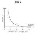
- Fig. 4 shows an experimental result of analyzing generation of reflected light H (crosstalk) from the adjacent layer in the conventional example. This experimentation was for checking the layer distance dependency of the reflected light H (crosstalk), and calculating the layer distance dependency of the proportion of the reflected light (crosstalk) from the adjacent layer where NA of the condensed beam is "0.65" and the equivalent light receiving area is 100 ⁇ m 2 .
- an optical head which reads signals receives light by a photodetector by enlarging and imaging reflected light from a condensing spot, and assuming that the enlargement ratio is M and the light receiving area of the photodetector is A, A/M 2 in which the light receiving area calculated at the condensing spot is the equivalent light receiving area.
- the equivalent light receiving area is 100 ⁇ m 2 , it is a typical value of an optical head, but the stroke increases as the area becomes larger.
- Fig. 4 when the crosstalk from the adjacent layer is set to about 5% which can be disregarded with respect to generation of signals, if the broken line (crosstalk) in Fig. 5B is not more than 5%, it is an allowable crosstalk amount. If the adjacent layer distance becomes not more than 30 ⁇ m, it is found that it exceeds the allowable crosstalk amount. For example, in a DVD-ROM, the adjacent layer distance is set to not less than 40 ⁇ m, so there is no problem.
- the layer distance must be set to not less than 30 ⁇ m.
- the crosstalk cannot be disregarded in such a small layer distance, so if a structure such as pits or grooves is formed in the adjacent layer, noises may be caused when readout. Therefore, in a general pit recording surface, there is caused a disadvantage that it is impossible to add error correction codes of the sufficient amount to record signals by considering the noise amount.
- BCA burst cutting area
- an optical disc medium includes a plurality of information recording layers accessible from the same light incident surface, in which each layer has a predetermined information recording area.
- An area which is on the inner peripheral side of the information recording area and has a predetermined same radial range in each layer is a burst cutting area forming zone.
- a burst cutting area (BCA) is provided in the burst cutting area forming zone of one information recording layer among a plurality of information recording layers (which may be set near the innermost peripheral edge), and burst cutting area forming zones in the remaining information recording layers are formed as mirror surfaces.
- the burst cutting area may be set with a predetermined distance from the information recording area located on the outer peripheral side thereof. With this configuration, interference by an information recording layer is reduced. In particular, in a disc medium having a plurality of layers, even there is eccentric in the respective layers, the influence is avoidable, whereby it is possible to read signals on the burst cutting area stably.
- the burst cutting area (BCA) it may be provided in an information recording layer which is the farthest from the same light incident surface, among the plurality of information recording layers. Even with this configuration, it is possible to read BCA signals stably same as the case described above. Further, there is an advantage that information reading from each information recording layer is performed smoothly.
- burst cutting area forming zone in which the burst cutting area is provided, all parts other than a part where the burst cutting area is provided may be formed as mirror surfaces. Even with this configuration, it is possible to read BCA signals stably same as the case described above.
- Information written with a plurality of line segments of low reflectance which are constitutional elements of the burst cutting area may be set by changing spaces between the line segments of low reflectance.
- the length of the plurality of line segments of low reflectance which are constitutional elements of the burst cutting area may be set to a length capable of allowing an eccentric amount of a track of each information recording layer.
- BCA burst cutting area
- the layer distance of the information recording layers of the optical disc medium according to the present invention may be not more than 30 ⁇ m. Even with this configuration, it is possible to obtain an optical disc medium in which mirror surfaces work effectively and operational effects that the above-described respective inventions have can be carried out more securely.
- an optical disc device includes: an optical head, into which the optical disc medium described above is loaded, for reading predetermined data from the optical disc medium; and a main controller for controlling the operation of the optical head, and is configured to read and output information from the optical head.
- the main controller includes: a mirror surface detecting function which is operated when focusing is performed to a radial area of the burst cutting area of the optical disc medium or when movement to the burst cutting area is performed after focusing has been performed to another area of the information recording layer, and which detects that the information recording layer after focusing has been performed is a mirror surface; and an interlayer jump controlling function which is operated when a detection result is not a mirror surface and which urges an interlayer jump operation to another information recording layer.
- an optical disc device includes: an optical head, into which the optical disc medium described above is loaded, for reading predetermined data from the optical disc medium; a data reading circuit for reading and outputting data outputted from the optical head; and a main controller for drive-controlling the data reading circuit.
- the optical head has an interlayer jump drive circuit for jump-moving a condensing spot of the optical head from one information recording layer of the optical disc medium to another information recording layer.
- the main controller is so configured to include: a recording layer determining function which is operated based on reflected light data inputted in the data reading circuit and which determines whether the optical head selects an information recording layer having a burst cutting area; and an interlayer jump controlling function which is operated based on a negative determination by the recording layer determining function and which causes the optical head to jump to another recording layer via the interlayer jump driving circuit.
- the recording layer determining function of the main controller may be a mirror surface detecting function which is operated when focusing is performed to a radial area of the burst cutting area corresponding to an outside instruction of the optical head or when movement to the burst cutting area is performed after focusing has been performed to another area of the information recording layer, and which determines whether detected data from the optical head is reflected data from the mirror surface.
- the present invention it is possible to read the burst cutting area (BCA) and written information stably and efficiently by excluding interference by other recording layers and scattering of readout light. Thereby, it is possible to provide excellent optical disc medium and optical disc device capable of effectively achieving information management based on the optical disc medium including identification of a plurality of optical disc media, which has not been achieved conventionally.
- An optical disc medium 1 has basically such a configuration that a burst cutting area forming zone is provided on the inner peripheral side of the information recording area 20 accessed from a light incident surface 1A, a burst cutting area (BCA) 101 is provided in a part of the burst cutting area forming zone, and the remaining part of the burst cutting area forming zone is formed as a mirror surface 5.
- a burst cutting area forming zone is provided on the inner peripheral side of the information recording area 20 accessed from a light incident surface 1A
- a burst cutting area (BCA) 101 is provided in a part of the burst cutting area forming zone
- the remaining part of the burst cutting area forming zone is formed as a mirror surface 5.
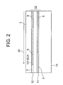
- the optical disc medium 1 according to the embodiment of the present invention shown in Fig. 2 is configured such that the information recording areas 20 are arranged in multiple layers (11, 12), and the burst cutting area (BCA) 101 is provided in a part of the burst cutting area forming zone provided in one of the information recording layers, and the burst cutting area forming zones of the remaining information recording layer are formed as mirror surfaces 5. More specific explanation will be given by using Figs. 1A to 3.
- the optical disc medium 1 has multi-layered information recording layers 10 (two layers in the present embodiment) accessed from the light incident surface 1A. More specifically, the optical disc medium 1 includes two layers, that is, a 0 th information recording layer 11 and a 1 st information recording layer 12, in this order from the side of the light incident surface 1A, as shown in Fig. 2.
- Each of the information recording layers 11 and 12 has predetermined information recording areas 20.
- an area which is on the inner peripheral side of the information recording area 20 of each layer and has a predetermined same radius range is a burst cutting area 101.
- the burst cutting area (BCA) 101 is provided near the innermost peripheral edge in either information recording layer (e.g., the 1 st information recording layer 12) of the plurality of information recording layers 11 and 12 described above, and the burst cutting area forming zone in the remaining information recording layer (the 0 th information recording layer 11) is formed of the mirror surface 5. This will be explained in more detail.
- Fig. 1 shows an exemplary arrangement of the burst cutting area (BCA) 101 with respect to the optical disc medium 1.
- the BCA 101 is formed inside the information recording area 20.
- the reference numeral 2 shows a record track formed on the information recording area 20.
- the BCA 101 of the present embodiment is formed on the inner peripheral side of the record track 2.
- the burst cutting area (BCA) does not have a track so it is impossible to apply track servo. Therefore, if the burst cutting area (BCA) is formed at a radius position in the middle of the record track 2, access operation between the front and back tracks becomes difficult. In this embodiment, this inconvenience is improved in advance.
- the BCA 101 may be formed all over the same circumference, or may be formed on a part of the circumference as shown in Fig. 1A. Further, in the radius area in which the BCA 101 is provided (burst cutting area forming zone), track servo cannot be applied, so the width of the BCA 101 in the radial direction (length L of each line segment 101a of low reflectance constituting the BCA) is set to have a width sufficiently larger comparing with the eccentric amount of the record track 2.
- Fig. 1B shows a configuration example of the BCA pattern to be formed.
- This BCA pattern is formed by the same means of the BCA pattern of the conventional example described above.
- information signals are written by changing spaces between line segments 101a of low reflectance having almost same widths.
- the line segments 101a of low reflectance are formed by laser irradiation, the line segments 101a of low reflectance can be formed by changing the irradiation position, so manufacturing becomes easy.
- information may be written by changing the width of a low reflectance part and the width of a high reflectance part arbitrarily.
- Fig. 2 shows a partial sectional view of the optical disc medium 1.
- the optical disc medium 1 is made of a transparent member as its material, and incorporates two information recording layers (the 0 th information recording layer 11 and the 1 st information recording layer 12) accessible from the light incident surface 1A thereof.
- a pit recording surface 6 is provided up to the almost same inner peripheral radius.
- the BCA 101 is provided near the innermost peripheral edge of the information recording area 20 of the 1 st information recording layer 12.
- the 0 th information recording layer 11 the area of the same radius position is formed as the mirror surface 5.
- the information recording area 20 means a range where information that the optical disc device should read exists.
- the BCA 101 is formed in the information recording layer 12 and the other information recording layer 11 is formed as a mirror surface without a pit or anything, no fluctuation is caused in a condensed beam passing through or being reflected at the mirror surface 5. Therefore, even in the case where the adjacent layer distance is not more than 30 ⁇ m in particular, it is possible to read signals of the BCA 101 stably without being interfered by the other layer. Further, even compared with the case of forming a pit recording surface all over the 0 th information recording layer 11, the condensed beam to the 1 st information recording layer 12 will never be suffered from scattering loss by the pits of the 0 th information recording layer 11. Therefore, more signal light amount can be obtained from the BCA 101, so stable BCA detection is achieved.
- the 0 th information recording layer 11 and the 1 st information recording layer 12 are formed by sticking together, there may be a case where the pit recording surface and the BCA is overlapped, depending on the positions in the circumferential direction due to the difference in the eccentric amounts of the two layers.
- the BCA is formed to have a sufficiently large radius width compared with the eccentric amount (the length of the line segments 101a of low resistance of the BCA is set sufficiently long compared with the eccentric amount), it is possible to read signals on the BCA 101 effectively without being affected by the pit recording surface 6.
- mirror surfaces 5 are formed in all information recording layers, even in the radius area with the pit recording surface 6 formed in the area on the outer peripheral side of the BCA 101, as shown in Fig. 2. Therefore, overlapping of the pit recording surface 6 of the 0 th information recording layer 11 by the eccentricity between the two layers at the time of manufacturing is surely prevented, so readout stability can be further improved.
- the BCA 101 is formed in the 1 st information recording layer 12 in the example of Fig. 2, it may be formed in the 0 th information recording layer 11, and the 1 st information recording layer 12 may be formed as a mirror surface.
- the 0 th information recording layer 11 is a recording layer having a semi-transmissive characteristic for light, but the 1 st information recording layer 12 can be formed as a recording layer having only a reflection characteristic.
- the 1 st information recording layer 12 has larger light absorption and only a low laser irradiation power is required, so there is an advantage of easy processing.
- the formation of the BCA 101 described above can be applied not only to a pit recording medium such as a ROM but also to an recordable or rewritable optical disc in which grooves are formed instead of pits. Further, even in the case where the information recording layers are formed of multiple layers more than two layers such as three layers or four layers, the effect of the present invention can be achieved by forming the BCA 101 in only one layer thereof and forming the remaining layers as mirror surfaces.
- the optical disc device includes an optical head 51, into which the optical disc medium 1 described above is loaded, for reading predetermined data from the optical disc medium 1, and a main controller 53 for controlling operation of the optical head 51, and is so configured as to read and output information from the optical head 51.
- the main controller 53 is configured to include: a mirror surface detecting function which is operated when focusing is performed to the radius area of the burst cutting area 101 of the optical disc medium 1, and detects that the information recording layer after focusing has been performed is a mirror surface 105; and interlayer jump controlling function which is operated if the detection result is not the mirror surface 105 and instructs an interlayer jump operation to another information recording layer.
- an optical disc device includes: the optical head 51, into which the optical disc medium 1 described above is loaded, for reading predetermined data from the optical disc medium 1; a data reading circuit 52 for reading and outputting data outputted from the optical head 51; and the main controller 53 for drive-controlling the data reading circuit 52.
- the optical head 51 is provided with an interlayer jump drive circuit 55 which jump-moves the condensed spot of the optical head 51 from either one of the information recording layer 11 and 12 of the optical disc medium 1 to the other information recording layer 12 or 11.
- the reference numeral 56 shows a spindle for rotationally driving the optical head 51
- the reference numeral 60 shows an information output unit for outputting readout data with a control by the main control unit 53.
- the main control unit 53 has a recording layer determining function which is operated based on reflected light data inputted in the data reading circuit 52 and determines whether the optical head 51 selects an information recording layer with the burst cutting area (BCA) 101. Further, the main controller 53 has an interlayer jump controlling function which is operated based on a negative determination by the recording layer determining function, and causes the optical head 51 to jump from one information recording layer 11 (12) to the other information recording layer 12(11) via the interlayer jump drive circuit 55.
- the recording layer determining function of the main controller 53 may specifically be a mirror surface detecting function which is operated when the optical head 51 performs focusing to the radius area of the burst cutting area (BCA) 101 (see Fig. 1) corresponding to an outside instruction, and determines whether detected data by the optical head 51 is reflected data from the mirror surface 5.
- the optical head 51 when the optical disc 1 having multi-layered information recording layers is set to the spindle 56, reading or writing of information is performed by the optical head 51.
- the optical head 51 reads information in the burst cutting area (BCA) 101, after focusing is performed to the information recording layers 10, the data reading circuit 52 takes in signals of the reflected light, and the main controller 53 determines whether the condensing spot e of the optical head 51 correctly scans the information recording layer 12 with the BCA 101. If it is determined as the mirror surface 5, the interlayer jump drive circuit 55 is operated immediately so as to cause the optical head 51 to jump to another information recording layer to thereby try to read the BCA 101.
- BCA burst cutting area
- the burst cutting area (BCA) 101 in forming a burst cutting area (BCA) in an area having a predetermined radial range set near the innermost peripheral edge of an information recording area, in which information thereof is read out by the optical disc device, in the optical disc medium 1 having two or more information recording layers 20 accessible from the same light incident surface 1A, the burst cutting area (BCA) 101 is formed in only one information recording layer 12, and the remaining information recording layers are formed as mirror surfaces.
- This optical disc medium 1 is characterized in that the burst cutting area (BCA) 101 is provided in the farthermost information recording layer 12 from the light incident surface.
- mirror surfaces 5 are set in all information recording layers 11 and 12 in a predetermined radial range outside the outer peripheral edge of the burst cutting area (BCA) 101.
- identification of a position can be performed quickly without depending on track servo with high accuracy, and further, in the areas of the mirror surfaces 5, no fluctuation is caused in a condensed beam passing through or being reflected partially at the mirror surfaces 5. Therefore, no interference by the remaining (other) information recording layers 11 is caused, so it is possible to read signals in the burst cutting area (BCA) 101 stably at any time.
- BCA burst cutting area
- the burst cutting area (BCA) 101 described above is set with a predetermined distance with respect to the information recording area on the outer peripheral side thereof, so interference by the information recording area becomes less.
- the burst cutting area (BCA) 101 is provided in the farthest information recording layer 12 from the same light incident surface 1A of the information recording layers 11 and 12, so setting of processing of line segments having low reflectance constituting the BCA becomes easy, whereby it is possible to read BCA signals stably same as that described above.
- the length of a plurality of line segments 101a of low reflectance which are constituent elements of the burst cutting area (BCA) 101 is set to be a length capable of allowing the eccentric amount of the track. Therefore, even if the burst cutting area (BCA) 101 is provided eccentrically for example, it is possible to read BCA signals in a stable state without depending on the track servo. This also leads to an improvement in the reliability of the disc medium. Further, in the embodiment described above, even if the distance between layers in the information recording layers is not more than 30 ⁇ m, it is possible to detect the burst cutting area (BCA) 101 effectively by coping with the distance effectively.
- the optical disc device which reads an optical disc medium having two or more information recording layers, includes a function of detecting that the information recording layer is a mirror surface when focusing is performed to the radius area of the burst cutting area of the optical disc medium, and a function of performing an interlayer jump operation to a predetermined information recording layer by using the detection result. Therefore, it is possible to obtain detection signals securely by means of the reflected information from the mirror surface 5, and by using them, it is possible to perform an operation of reading the burst cutting area (BCA) 101 smoothly and securely.
- BCA burst cutting area
Landscapes
- Optical Recording Or Reproduction (AREA)
- Optical Record Carriers And Manufacture Thereof (AREA)
- Moving Of The Head For Recording And Reproducing By Optical Means (AREA)
Applications Claiming Priority (1)
| Application Number | Priority Date | Filing Date | Title |
|---|---|---|---|
| JP2005159073A JP2006338718A (ja) | 2005-05-31 | 2005-05-31 | 光ディスク媒体および光ディスク装置 |
Publications (2)
| Publication Number | Publication Date |
|---|---|
| EP1729293A2 true EP1729293A2 (de) | 2006-12-06 |
| EP1729293A3 EP1729293A3 (de) | 2007-06-27 |
Family
ID=36992567
Family Applications (1)
| Application Number | Title | Priority Date | Filing Date |
|---|---|---|---|
| EP06010502A Withdrawn EP1729293A3 (de) | 2005-05-31 | 2006-05-22 | Optisches Plattenmedium und optische Plattenvorrichtung |
Country Status (4)
| Country | Link |
|---|---|
| US (1) | US20060271942A1 (de) |
| EP (1) | EP1729293A3 (de) |
| JP (1) | JP2006338718A (de) |
| CN (1) | CN1873792A (de) |
Families Citing this family (6)
| Publication number | Priority date | Publication date | Assignee | Title |
|---|---|---|---|---|
| US8031582B2 (en) * | 2005-09-30 | 2011-10-04 | Nec Corporation | Optical information recording medium, BCA information recorder, and BCA information recording method |
| JP2007328873A (ja) * | 2006-06-08 | 2007-12-20 | Toshiba Corp | 追記型多層光ディスク、記録方法、再生方法、および記録装置 |
| JP2008135111A (ja) * | 2006-11-28 | 2008-06-12 | Toshiba Corp | 光ディスク装置および光ディスク再生方法 |
| JP2010140576A (ja) | 2008-12-15 | 2010-06-24 | Hitachi Ltd | 多層光ディスクおよび光ディスク装置 |
| WO2010134300A1 (ja) | 2009-05-21 | 2010-11-25 | パナソニック株式会社 | メモリコントローラ、不揮発性記憶装置、アクセス装置、不揮発性記憶システム、データ書き込み方法、および、プログラム |
| US9633688B2 (en) * | 2013-07-16 | 2017-04-25 | Sharp Kabushiki Kaisha | Reproducing device |
Citations (2)
| Publication number | Priority date | Publication date | Assignee | Title |
|---|---|---|---|---|
| WO2002037483A1 (en) | 2000-11-06 | 2002-05-10 | Matsushita Electric Industrial Co., Ltd. | Optical recording medium, optical recording medium production method, optical recording medium production apparatus, program, and medium |
| WO2003021580A2 (en) * | 2001-09-05 | 2003-03-13 | Koninklijke Philips Electronics N.V. | Optical data storage medium and methods for reading and writing such a medium |
Family Cites Families (6)
| Publication number | Priority date | Publication date | Assignee | Title |
|---|---|---|---|---|
| US5726969A (en) * | 1994-12-28 | 1998-03-10 | Matsushita Electric Industrial Co., Ltd. | Optical recording medium having dual information surfaces |
| KR100449458B1 (ko) * | 1996-07-31 | 2004-09-21 | 도또리 상요 덴기 가부시끼가이샤 | 광 디스크 장치 |
| DE69934424T2 (de) * | 1998-10-21 | 2007-10-31 | Matsushita Electric Industrial Co., Ltd., Kadoma | Optisches informationsaufzeichnungsmedium, und verfahren und gerät zur aufzeichnung und wiedergabe |
| JP2001189051A (ja) * | 1999-12-28 | 2001-07-10 | Pioneer Electronic Corp | コード判定装置及び方法、記録媒体判別装置及び方法並びに情報記録装置及び方法 |
| JP4150155B2 (ja) * | 2000-10-10 | 2008-09-17 | 株式会社日立製作所 | 情報記録媒体、情報の記録方法、再生方法、記録記録装置及び情報再生装置 |
| DE602004032002D1 (de) * | 2003-10-08 | 2011-05-12 | Panasonic Corp | Verfahren zur Aufzeichnung von Indentifikationsinformationen, Vorrichtung dafür und Informationsaufzeichnungsmedium |
-
2005
- 2005-05-31 JP JP2005159073A patent/JP2006338718A/ja active Pending
-
2006
- 2006-05-22 EP EP06010502A patent/EP1729293A3/de not_active Withdrawn
- 2006-05-26 US US11/441,126 patent/US20060271942A1/en not_active Abandoned
- 2006-05-31 CN CNA2006100876834A patent/CN1873792A/zh active Pending
Patent Citations (2)
| Publication number | Priority date | Publication date | Assignee | Title |
|---|---|---|---|---|
| WO2002037483A1 (en) | 2000-11-06 | 2002-05-10 | Matsushita Electric Industrial Co., Ltd. | Optical recording medium, optical recording medium production method, optical recording medium production apparatus, program, and medium |
| WO2003021580A2 (en) * | 2001-09-05 | 2003-03-13 | Koninklijke Philips Electronics N.V. | Optical data storage medium and methods for reading and writing such a medium |
Also Published As
| Publication number | Publication date |
|---|---|
| JP2006338718A (ja) | 2006-12-14 |
| EP1729293A3 (de) | 2007-06-27 |
| CN1873792A (zh) | 2006-12-06 |
| US20060271942A1 (en) | 2006-11-30 |
Similar Documents
| Publication | Publication Date | Title |
|---|---|---|
| JP2007519143A (ja) | 情報保存媒体、これに記録された情報再生装置及び方法 | |
| US20050141351A1 (en) | Recording type optical disk apparatus and optical disk medium | |
| JP5429238B2 (ja) | Bca用情報記録装置,およびbca用情報記録方法 | |
| EP1729293A2 (de) | Optisches Plattenmedium und optische Plattenvorrichtung | |
| EP1202255A2 (de) | Mehrschichtiges Informationsaufzeichnungsmedium und Aufzeichnungsgerät dafür | |
| US6720056B2 (en) | Multi-layer information recording medium | |
| EP1628291B1 (de) | Verfahren zum Herstellen von optischen Plattenmedien vom hoch-zu-niedrig und niedrig-zu-hoch Reflektionstyp | |
| CN100452182C (zh) | 信息记录装置和方法 | |
| EP1548731B1 (de) | Optisches Plattengerät, Verfahren zur Steuerung desselben und Aufzeichnungsmedium | |
| JP4072546B2 (ja) | 2層光ディスク | |
| US8315134B2 (en) | Optical disk containing information about usability of recording layers and optical disk apparatus for reproducing the optical disk | |
| US20100014403A1 (en) | Method and apparatus of discriminating different types of optical discs | |
| EP1764783B1 (de) | Informationsaufzeichnungsvorrichtung und -verfahren | |
| EP1603125B1 (de) | Aufzeichnungsverfahren und -Vorrichtung für optische Platte | |
| JP3996339B2 (ja) | 光学式記録再生装置および光ディスク判別方法並びに光学式記録再生装置の起動方法 | |
| EP1956593B1 (de) | Optische plattenvorrichtung | |
| KR20050071331A (ko) | 정보저장매체, 이에 기록된 정보재생장치 및 방법 | |
| US20060062134A1 (en) | Optical storage medium and recording/reproduction apparatus and method | |
| CN101297360A (zh) | 包含用于指示可记录区域是否被完全记录的指示区域的光学记录载体,以及与这种记录载体一起使用的设备 | |
| JP2007102984A (ja) | 光ディスク | |
| HK1090740B (en) | Information recording apparatus and method |
Legal Events
| Date | Code | Title | Description |
|---|---|---|---|
| PUAI | Public reference made under article 153(3) epc to a published international application that has entered the european phase |
Free format text: ORIGINAL CODE: 0009012 |
|
| AK | Designated contracting states |
Kind code of ref document: A2 Designated state(s): AT BE BG CH CY CZ DE DK EE ES FI FR GB GR HU IE IS IT LI LT LU LV MC NL PL PT RO SE SI SK TR |
|
| AX | Request for extension of the european patent |
Extension state: AL BA HR MK YU |
|
| PUAL | Search report despatched |
Free format text: ORIGINAL CODE: 0009013 |
|
| AK | Designated contracting states |
Kind code of ref document: A3 Designated state(s): AT BE BG CH CY CZ DE DK EE ES FI FR GB GR HU IE IS IT LI LT LU LV MC NL PL PT RO SE SI SK TR |
|
| AX | Request for extension of the european patent |
Extension state: AL BA HR MK YU |
|
| 17P | Request for examination filed |
Effective date: 20071023 |
|
| AKX | Designation fees paid |
Designated state(s): DE FR GB |
|
| 17Q | First examination report despatched |
Effective date: 20080305 |
|
| STAA | Information on the status of an ep patent application or granted ep patent |
Free format text: STATUS: THE APPLICATION IS DEEMED TO BE WITHDRAWN |
|
| 18D | Application deemed to be withdrawn |
Effective date: 20090623 |