EP1728060B1 - Sensormodul mit einem kondensator emv- und esd-schutz - Google Patents
Sensormodul mit einem kondensator emv- und esd-schutz Download PDFInfo
- Publication number
- EP1728060B1 EP1728060B1 EP04821722A EP04821722A EP1728060B1 EP 1728060 B1 EP1728060 B1 EP 1728060B1 EP 04821722 A EP04821722 A EP 04821722A EP 04821722 A EP04821722 A EP 04821722A EP 1728060 B1 EP1728060 B1 EP 1728060B1
- Authority
- EP
- European Patent Office
- Prior art keywords
- sensor
- housing part
- housing
- sensor module
- inner space
- Prior art date
- Legal status (The legal status is an assumption and is not a legal conclusion. Google has not performed a legal analysis and makes no representation as to the accuracy of the status listed.)
- Active
Links
- 239000003990 capacitor Substances 0.000 title claims abstract description 18
- 239000004020 conductor Substances 0.000 claims abstract description 32
- 230000001681 protective effect Effects 0.000 claims abstract description 11
- 230000002093 peripheral effect Effects 0.000 claims abstract description 7
- 239000000463 material Substances 0.000 claims abstract description 6
- 239000000853 adhesive Substances 0.000 claims description 7
- 230000001070 adhesive effect Effects 0.000 claims description 7
- 238000005192 partition Methods 0.000 claims description 7
- 239000003566 sealing material Substances 0.000 claims description 4
- XUIMIQQOPSSXEZ-UHFFFAOYSA-N Silicon Chemical compound [Si] XUIMIQQOPSSXEZ-UHFFFAOYSA-N 0.000 claims description 2
- 229910052710 silicon Inorganic materials 0.000 claims description 2
- 239000010703 silicon Substances 0.000 claims description 2
- 238000001746 injection moulding Methods 0.000 claims 1
- 238000002347 injection Methods 0.000 description 3
- 239000007924 injection Substances 0.000 description 3
- 238000007789 sealing Methods 0.000 description 3
- 238000003466 welding Methods 0.000 description 3
- 238000009530 blood pressure measurement Methods 0.000 description 2
- 238000004519 manufacturing process Methods 0.000 description 2
- 239000012528 membrane Substances 0.000 description 2
- 239000004065 semiconductor Substances 0.000 description 2
- 239000013464 silicone adhesive Substances 0.000 description 2
- 230000001419 dependent effect Effects 0.000 description 1
- 238000011161 development Methods 0.000 description 1
- 230000018109 developmental process Effects 0.000 description 1
- 230000003993 interaction Effects 0.000 description 1
- 238000000034 method Methods 0.000 description 1
- 229920001296 polysiloxane Polymers 0.000 description 1
- 239000012945 sealing adhesive Substances 0.000 description 1
- 238000005476 soldering Methods 0.000 description 1
- 239000000126 substance Substances 0.000 description 1
Images
Classifications
-
- G—PHYSICS
- G01—MEASURING; TESTING
- G01L—MEASURING FORCE, STRESS, TORQUE, WORK, MECHANICAL POWER, MECHANICAL EFFICIENCY, OR FLUID PRESSURE
- G01L19/00—Details of, or accessories for, apparatus for measuring steady or quasi-steady pressure of a fluent medium insofar as such details or accessories are not special to particular types of pressure gauges
- G01L19/06—Means for preventing overload or deleterious influence of the measured medium on the measuring device or vice versa
- G01L19/069—Protection against electromagnetic or electrostatic interferences
-
- G—PHYSICS
- G01—MEASURING; TESTING
- G01L—MEASURING FORCE, STRESS, TORQUE, WORK, MECHANICAL POWER, MECHANICAL EFFICIENCY, OR FLUID PRESSURE
- G01L19/00—Details of, or accessories for, apparatus for measuring steady or quasi-steady pressure of a fluent medium insofar as such details or accessories are not special to particular types of pressure gauges
- G01L19/14—Housings
- G01L19/142—Multiple part housings
- G01L19/143—Two part housings
-
- G—PHYSICS
- G01—MEASURING; TESTING
- G01L—MEASURING FORCE, STRESS, TORQUE, WORK, MECHANICAL POWER, MECHANICAL EFFICIENCY, OR FLUID PRESSURE
- G01L19/00—Details of, or accessories for, apparatus for measuring steady or quasi-steady pressure of a fluent medium insofar as such details or accessories are not special to particular types of pressure gauges
- G01L19/14—Housings
- G01L19/148—Details about the circuit board integration, e.g. integrated with the diaphragm surface or encapsulation
Definitions
- the invention relates to a sensor module, in particular a pressure sensor module having the features of the preamble of independent claim 1.
- EMC capacitors are used in sensor modules. Although it is possible to integrate such capacitors in the semiconductor pressure sensor, this requires a considerable overhead in the manufacture of the pressure transducer. In addition, the integrated capacitors often do not meet the requirements for effective ESD protection. Therefore, the capacitors are installed in known sensor modules elsewhere than the sensor assembly in the sensor housing.
- a pressure sensor module in a two-chamber design is known.
- the housing has a housing part with therein partially embedded electrical conductors, which are contacted via bonding wire connections to a printed circuit board.
- the sensor housing further has a pressurized first inner space, in which a sensor arrangement is arranged, and a second inner space sealed with respect to the first inner space, in which an EMC protection circuit with protective capacitors is arranged.
- Sensor arrangement and EMC protection circuit are arranged together on a circuit board. About conductor tracks of the circuit board, the electrical connection of the protection circuit is made with the sensor arrangement.
- the first interior of the sensor housing further comprises a frame-like receiving part is arranged with a receptacle formed by a circumferential wall, in which recording the sensor assembly used and for protection with a filled in the receptacle protective cover, for example a silicone gel, is covered.
- a filled in the receptacle protective cover for example a silicone gel
- the sensor module according to the invention with the features of claim 1 allows a simple and compact design of the sensor module, which can be dispensed with a printed circuit board as an electrical connection means.
- the sensor arrangement with the sensor element is inserted into a receiving part filled with a protective cover and contacted with electrical connection elements arranged on the receiving part.
- the receiving part is arranged in the first interior of the sensor housing.
- the connection elements are directly connected in the first housing space with connection sections of the electrical conductors, which can be advantageously carried out by welding.
- the at least one arranged in the second interior EMC capacitor is connected via an electrically conductive material, in particular a conductive adhesive, with at least one of the electrical conductors. It is particularly advantageous that the capacitors arranged in the second interior do not have to be protected with a gel cover. Interactions between the gel and the conductive adhesive are thus avoided.
- the gel covers the entire first interior and air pockets in the gel to damage the sensor assembly or the bonding wire connections between the sensor assembly and the electrical Can lead connections. Since the electrical conductors, which are partially embedded in the housing part, are led to the second interior space, otherwise, with a negative pressure in the first housing interior, air could pass from the second interior space along the electrical conductors into the first interior space. If this air escaped directly under the gel, air bubbles would form in the gel which, in the case of pressure fluctuations, tend to expand explosively and cause damage to the sensor element and, above all, to the bonding wire connections.
- air which reaches the first interior space along the electrical conductors can advantageously not escape below the protective cover of the sensor arrangement, since this is located in the receiving part together with the bonding wires. Air bubbles in the protective cover of the sensor element are thus avoided.
- the receiving part is inserted into a formed on the first housing part second receptacle, which second receptacle has a wall surrounding the receiving part. Between the wall surrounding the receiving part and the receiving part, a material covering the electrical connection point of the electrical conductors and the electrical connection elements is filled, whereby the connection point is protected from aggressive substances. Since the electrical connection of the electrical connection elements with the electrical conductors can take place, for example, by welding and is therefore very robust, damage to the electrical connection point is not possible by air escaping within the second receptacle. In addition, other materials which exclude air ingress may be chosen here as the protective cover of the sensor arrangement.
- the first housing part as an injection molded part in which the electrical conductors are partially embedded as stamped grid parts.
- the sensor module according to the invention can advantageously be designed both as an absolute pressure sensor with a pressure connection and as a relative pressure sensor with two pressure connections.
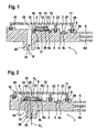
- Fig. 1 shows a first embodiment of a sensor module, which is designed as a pressure sensor module for absolute pressure measurement.
- the pressure sensor module 1 has a sensor housing 1 with a first housing part 2, which is manufactured as an injection molded part with electrical conductors 4 partially embedded therein.
- the electrical conductors 4 may be formed, for example, as stamped grid parts, wherein a plurality of electrically separate leadframe tracks are embedded in the plastic of the housing part 1.
- the electrical conductors 4 may be guided on one side of the sensor housing 1 to a plug-in connection 5 of the sensor module, where connecting portions 4d of the conductors or connector pins connected thereto are excluded from the plastic sheath.
- a second housing part 3 is provided as a lid, which is for example also made of plastic as an injection molded part and is mounted on the first housing part 1.
- a partition wall 22 and a peripheral wall 29 is formed on the second housing part 3.
- the two housing parts connected in this way form a sensor housing with a first inner space 10 and a second inner space 11, wherein the second inner space is separated from the first inner space 10 by the dividing wall 22 and is sealed off from it, so that different atmospheres and pressures occur in the two inner spaces can exist.
- the first housing part 2 further has a pressure port 20 with a pressure channel 21, which opens into the first inner space 10, so that a pressure P applied to the pressure port 20 also prevails in the inner space 10.
- the electrical conductors 4 have connection sections 4a, 4b and 4c, which are not embedded in the plastic of the housing part 2, but the inside of the first housing part 2 facing the first interior 10 or the second interior 11 of the sensor housing are excluded from the serving.
- At least one capacitor 7 arranged in the second housing interior 11 is contacted with a connection section 4c of an electrical conductor 4, preferably by means of a conductive adhesive arranged between the connection section 4c and the capacitor 7.
- the capacitor 7 is a protective capacitor for improving the electromagnetic compatibility (EMC protection) of the sensor module and for protection against electrostatic discharges. It is therefore arranged between the connection sections 4d of the plug connection 5 and connection sections 4a, 4b, which are provided for contacting the sensor arrangement.
- the sensor arrangement 12, 13 comprises a sensor element 12, for example a semiconductor pressure sensor with a silicon chip, on the upper side of which pressure-sensitive elements are arranged, and a base 13.
- the sensor arrangement is inserted into a box-shaped receiving part 6 (premold), which has a through a receptacle 18 has a bottom 17 and a peripheral wall 16 formed.
- the receiving part 6 may for example consist of plastic.
- the receiving part 6 further comprises connecting elements 19, which from the receptacle 18 by the circumferential Wall 16 are guided in the first inner space 10 and there with the disposed on the inside of the first housing part 2 connecting portions 4a, 4b (in Fig. 1 By way of example, two connection sections 4a and 4b are shown) of the electrical conductors 4, for example by welding.
- connection sections 4a, 4b it is, of course, also possible to produce the electrical connection of the electrical connection elements 19 to the connection sections 4a, 4b by soldering or press-contacting or in another suitable manner.
- the not connected to the conductors 4 ends of the connecting elements 19 are connected in the interior of the receptacle 18, for example via bonding wire connections to the sensor element 12.
- the receptacle 18 of the receiving part 6 is to protect the sensor element with a protective cover 14, such as a gel, filled. When pressure is applied to the interior 10, the pressure is transmitted to the sensor element 12 via the elastic gel.
- the inner side of the first housing part 2 facing the first inner space 10 has a second receptacle 26 which is formed by a depression on the inner side of the first housing part 2 and has a circumferential wall 25 delimiting the second receptacle 26.
- the receiving part 6 is disposed within the bounded by the peripheral wall 25 receptacle 26. Between the wall 25 and the receiving part 6 is a the electrical connection point of the electrical conductors 4 and the electrical connection elements 19 covering material 9, for example, an adhesive, in particular a silicone adhesive arranged.
- the adhesive can advantageously be applied to the first housing part 1 together with the filling of the grooves 28.
- Fig. 2 shows an embodiment with a trained for reference pressure measurement sensor module. Same things are with the same reference numbers as in Fig. 1 Mistake.
- the receiving part 6 is arranged above the pressure channel 21 and provided with a recess in the bottom 17 for carrying out a pressure P1.
- the base 13 also has a recess, so that the sensor membrane of the sensor element 12 can be acted upon from below with a first pressure P1, which does not prevail in the first interior space 10, since the pressure channel 21 is sealed here against the first interior 10.
- the second housing part 3 has a second pressure port 30, through which the first inner space 10 and the resilient cover 14 made of gel, the upper side of the sensor membrane of the sensor element 12 with a pressure P2 can be acted upon as a reference pressure.
- the sensor element 12 and the bonding wire connection to the connection elements 19 are particularly well protected against damage, since air which could reach the first interior space 10 from the second interior space 11 along the plastic conductors 4 injected in plastic, There exits below the covering material and therefore can not cause damage to the bonding wire connection, since the bonding wire connection is protected against the ingress of air within the receiving part 6 is arranged.
Abstract
Description
- Die Erfindung betrifft ein Sensormodul, insbesondere ein Drucksensormodul mit den Merkmalen des Oberbegriffs des unabhängigen Anspruchs 1.
- Zur Verbesserung der elektromagnetischen Verträglichkeit (EMV-Schutz) und zum Schutz gegen elektrostatische Entladungen (ESD-Schutz) werden in Sensormodulen EMV-Kondensatoren eingesetzt. Obwohl es möglich ist, derartige Kondensatoren in den Halbleiterdruckaufnehmer zu integrieren, erfordert dies einen nicht unerheblichen Mehraufwand bei der Herstellung des Druckaufnehmers. Außerdem erfüllen die integrierten Kondensatoren oft die Anforderungen hinsichtlich eines wirksamen ESD-Schutzes nicht. Daher werden die Kondensatoren bei bekannten Sensormodulen an anderer Stelle als die Sensoranordnung in das Sensorgehäuse eingebaut.
- Aus der
DE 197 31420 A1 ist beispielsweise ein Drucksensormodul in Zweikammerbauweise bekannt. Das Gehäuse weist ein Gehäuseteil mit darin teilweise eingebetteten elektrischen Leitern auf, die über Bonddrahtverbindungen mit einer Leiterplatte kontaktiert sind. Das Sensorgehäuse weist weiterhin einen druckbeaufschlagten ersten Innenraum auf, in dem eine Sensoranordnung angeordnet ist, und einen gegenüber dem ersten Innenraum abgedichteten zweiten Innenraum auf, in dem eine EMV-Schutzschaltung mit Schutzkondensatoren angeordnet ist. Sensoranordnung und EMV-Schutzschaltung sind gemeinsam auf einer Leiterplatte angeordnet. Über Leiterbahnen der Leiterplatte wird die elektrische Verbindung der Schutzschaltung mit der Sensoranordnung hergestellt. In dem ersten Innenraum des Sensorgehäuses ist weiterhin ein rahmenartiges Aufnahmeteil mit einer durch eine umlaufende Wand gebildeten Aufnahme angeordnet, in welche Aufnahme die Sensoranordnung eingesetzt und zum Schutz mit einer in die Aufnahme eingefüllten Schutzabdeckung, beispielsweise einem Silikongel, abgedeckt ist. Nachteilig bei den bekannten Sensormodulen ist, dass die Anordnung der Leiterplatte in den beiden Innenräumen einen relativ großen Aufwand bei der Abdichtung der beiden Innenräume erforderlich macht, da Dichtungen oberhalb und unterhalb der Leiterplatte erforderlich sind, welche in aufwendiger Weise dort angeordnet werden müssen. - Das erfindungsgemäße Sensormodul mit den Merkmalen des Anspruchs 1 ermöglicht eine einfache und kompakte Bauweise des Sensormoduls, wobei auf eine Leiterplatte als elektrisches Verbindungsmittel verzichtet werden kann. Die Sensoranordnung mit dem Sensorelement ist in ein mit einer Schutzabdeckung gefülltes Aufnahmeteil eingesetzt und mit an dem Aufnahmeteil angeordneten elektrischen Anschlusselementen kontaktiert. Das Aufnahmeteil ist in dem ersten Innenraum des Sensorgehäuses angeordnet. Die Anschlusselemente werden in dem ersten Gehäuseraum mit Anschlussabschnitten der elektrischen Leiter direkt verbunden, was vorteilhaft durch Schweißen erfolgen kann. Der wenigstens eine in dem zweiten Innenraum angeordnete EMV-Kondensator wird über ein elektrisch leitendes Material, insbesondere einen Leitkleber, mit wenigstens einem der elektrischen Leiter verbunden. Besonders vorteilhaft ist, dass die in dem zweiten Innenraum angeordneten Kondensatoren nicht mit einer Gelabdeckung geschützt werden müssen. Wechselwirkungen zwischen dem Gel und dem Leitkleber werden so vermieden.
- Da die Sensoranordnung in ein eigenes Aufnahmeteil eingesetzt ist, welches beispielsweise mit einem Gel als Schutzabdeckung gefüllt ist, wird vorteilhaft vermieden, dass das Gel den gesamten ersten Innenraum bedeckt und Lufteinschlüsse im Gel zu einer Beschädigung der Sensoranordnung oder der Bondrahtverbindungen zwischen der Sensoranordnung und den elektrischen Anschlüssen führen können. Da die teilweise in das Gehäuseteil eingebetteten elektrischen Leiter bis zu dem zweiten Innenraum geführt sind, könnte nämlich ansonsten bei einem Unterdruck in dem ersten Gehäuseinnenraum Luft aus dem zweiten Innenraum entlang der elektrischen Leiter bis in den ersten Innenraum gelangen. Würde diese Luft direkt unter dem Gel austreten, so würden sich im Gel Luftbläschen bilden, die bei Druckschwankungen dazu neigen, sich explosionsartig auszudehnen und Beschädigungen am Sensorelement und vor allem an den Bonddrahtverbindungen zu verursachen.
- Bei dem erfindungsgemäßen Sensormodul kann Luft, die entlang der elektrischen Leiter in den ersten Innenraum gelangt, vorteilhaft nicht unterhalb der Schutzabdeckung der Sensoranordnung austreten, da sich diese zusammen mit den Bonddrähten in dem Aufnahmeteil befindet. Luftbläschen in der Schutzabdeckung des Sensorelementes werden so vermieden.
- Vorteilhafte Ausführungsbeispiele und Weiterentwicklungen der Erfindung werden durch die in den abhängigen Ansprüchen angegebenen Merkmale ermöglicht.
- Vorteilhaft ist das Aufnahmeteil in eine an dem ersten Gehäuseteil ausgebildete zweite Aufnahme eingesetzt, welche zweite Aufnahme eine das Aufnahmeteil umgebende Wand aufweist. Zwischen der das Aufnahmeteil umgebenden Wand und dem Aufnahmeteil ist ein die elektrische Verbindungsstelle der elektrischen Leiter und der elektrischen Anschlusselemente abdeckendes Material eingefüllt, wodurch die Verbindungsstelle vor aggressiven Substanzen geschützt wird. Da die elektrische Verbindung der elektrischen Anschlusselemente mit den elektrischen Leitern beispielsweise durch Verschweißen erfolgen kann und daher sehr robust ist, ist eine Beschädigung der elektrischen Verbindungsstelle durch innerhalb der zweiten Aufnahme austretende Luft nicht möglich. Außerdem können hier andere, das Eindringen von Luft ausschließende Materialien als für die Schutzabdeckung der Sensoranordnung gewählt werden.
- Besonders einfach ist die Herstellung des erstes Gehäuseteils als Spritzgussteil, in dem die elektrischen Leiter als Stanzgitterteile teilweise eingebettet sind.
- Das Sensorgehäuse weist vorteilhaft ein erstes Gehäuseteil und wenigstens ein zweites Gehäuseteil auf, wobei an dem ersten Gehäuseteil oder dem zweiten Gehäuseteil eine Trennwand ausgebildet ist und wobei durch Aufsetzen des zweiten Gehäuseteils auf das erste Gehäuseteil wenigstens der erste Innenraum und vorzugsweise auch der zweite Innenraum gebildet wird. Dadurch, dass eine umlaufende Wand des zweiten Gehäuseteils und eine an dem zweiten Gehäuseteil ausgebildete Trennwand in an dem ersten Gehäuseteil ausgebildete und mit Dichtmaterial gefüllte Nuten eingreifen, wird eine besonders einfache Abdichtung des Sensorgehäuses nach außen (bis auf wenigstens einen Druckanschluss) und eine Abdichtung des ersten Innenraums gegenüber dem zweiten Innenraum erreicht, wobei die Abdichtung vorteilhaft in nur einer Ebene in einem einzigen Prozessschritt angeordnet werden kann.
- Das erfindungsgemäße Sensormodul kann vorteilhaft sowohl als Absolutdrucksensor mit einem Druckanschluss als auch als Relativdrucksensor mit zwei Druckanschlüssen ausgestaltet sein.
- Ausführungsbeispiele der Erfindung sind in den Zeichnungen dargestellt und werden in der nachfolgenden Beschreibung erläutert. Es zeigt
-
Fig. 1 ein erstes Ausführungsbeispiel der Erfindung mit einem als Absolutdrucksensor ausgebildeten Sensormodul, -
Fig. 2 ein zweites Ausführungsbeispiel der Erfindung mit einem als Relativdrucksensor ausgebildeten Sensormodul. -
Fig. 1 zeigt ein erstes Ausführungsbeispiel eines Sensormoduls, welches als Drucksensormodul zur Absolutdruckmessung ausgebildet ist. Die Erfindung ist jedoch nicht auf Drucksensoren beschränkt und kann auch in anderen Sensoren zum Einsatz kommen. Das Drucksensormodul 1 weist ein Sensorgehäuse 1 mit einem ersten Gehäuseteil 2 auf, welches als Spritzgussteil mit darin teilweise eingebetteten elektrischen Leitern 4 gefertigt ist. Die elektrischen Leiter 4 können beispielsweise als Stanzgitterteile gebildet sein, wobei mehrere elektrisch voneinander getrennte Stanzgitterbahnen im Kunststoff des Gehäuseteils 1 eingebettet sind. Wie inFig. 1 zu erkennen ist, können die elektrischen Leiter 4 an einer Seite des Sensorgehäuses 1 zu einem Steckanschluss 5 des Sensormoduls geführt sein, wo Verbindungsabschnitte 4d der Leiter oder damit verbundene Steckerstifte von der Kunststoffumhüllung ausgenommen sind. - Weiterhin ist ein zweites Gehäuseteil 3 als Deckel vorgesehen, welches beispielsweise ebenfalls als Spritzgussteil aus Kunststoff gefertigt ist und auf das erste Gehäuseteil 1 aufgesetzt ist. An dem zweiten Gehäuseteil 3 ist eine Trennwand 22 und eine umlaufende Wand 29 ausgebildet. Beim Aufsetzten des zweiten Gehäuseteils 3 auf das erste Gehäuseteil 2, greift die umlaufende Wand 29 des zweiten Gehäuseteils 3 und die Trennwand 22 in an dem ersten Gehäuseteil 2 korrespondierend ausgebildete Nuten 28 ein, welche zuvor oder anschließend mit einem Dichtmaterial 8, insbesondere einer Dichtklebung beispielsweise mittels eines Silikonklebers, gefüllt werden. Die beiden derart verbundenen Gehäuseteile bilden ein Sensorgehäuse mit einem ersten Innenraum 10 und einem zweiten Innenraum 11, wobei der zweite Innenraum durch die Trennwand 22 von dem ersten Innenraum 10 getrennt ist und gegenüber diesem abgedichtet ist, so dass in den beiden Innenräumen unterschiedliche Atmosphären und Drücke bestehen können. Das erste Gehäuseteil 2 weist weiterhin einen Druckanschluss 20 mit einem Druckkanal 21 auf, welcher in den ersten Innenraum 10 einmündet, so dass ein an dem Druckanschluss 20 anliegender Druck P auch in dem Innenraum 10 herrscht.
- Wie in
Fig. 1 weiterhin dargestellt ist, weisen die elektrischen Leiter 4 Anschlussabschnitte 4a,4b und 4c auf, die nicht in den Kunststoff des Gehäuseteils 2 eingebettet sind, sondern die an der dem ersten Innenraum 10 oder dem zweiten Innenraum 11 des Sensorgehäuses zugewandten Innenseite des ersten Gehäuseteils 2 von der Umhüllung ausgenommen sind. Wenigstens ein in dem zweiten Gehäuseinnenraum 11 angeordneter Kondensator 7 ist mit einem Anschlussabschnitt 4c eines elektrischen Leiters 4, vorzugsweise mittels eines zwischen dem Anschlussabschnitt 4c und dem Kondensator 7 angeordneten Leitklebers, kontaktiert. Der Kondensator 7 ist ein Schutzkondensator zur Verbesserung der elektromagnetischen Verträglichkeit (EMV-Schutz) des Sensormoduls und zum Schutz gegen elektrostatische Entladungen. Er ist daher zwischen den Verbindungsabschnitten 4d des Steckanschlusses 5 und Anschlussabschnitten 4a,4b angeordnet, welche zur Kontaktierung der Sensoranordnung vorgesehen sind. - Die Sensoranordnung 12,13 umfasst ein Sensorelement 12, beispielsweise einen Halbleiter-Druckaufnehmer mit einem Silizium-Chip, auf dessen Oberseite druckempfindliche Elemente angeordnet sind, und einen Sockel 13. Die Sensoranordnung ist in ein kastenförmiges Aufnahmeteil 6 (Premold) eingesetzt, welches eine durch einen Boden 17 und eine umlaufende Wand 16 gebildete Aufnahme 18 aufweist. Das Aufnahmeteils 6 kann beispielsweise aus Kunststoff bestehen. Das Aufnahmeteil 6 weist weiterhin Anschlusselemente 19 auf, die von der Aufnahme 18 aus durch die umlaufende Wand 16 in den ersten Innenraum 10 geführt sind und dort mit den an der Innenseite des ersten Gehäuseteils 2 angeordneten Anschlussabschnitten 4a,4b (in
Fig. 1 sind beispielhaft zwei Anschlussabschnitte 4a und 4b dargestellt) der elektrischen Leiter 4 beispielsweise durch Schweißen verbunden sind Es ist natürlich auch möglich, die elektrische Verbindung der elektrischen Anschlusselemente 19 mit den Anschlussabschnitten 4a,4b durch Löten oder Presskontaktierung oder in anderer geeigneter Weise herzustellen. Die nicht mit den Leitern 4 verbundenen Enden der Anschlusselemente 19 sind im Inneren der Aufnahme 18 beispielsweise über Bonddrahtverbindungen mit dem Sensorelement 12 verbunden. Die Aufnahme 18 des Aufnahmeteils 6 ist zum Schutz des Sensorelementes mit einer Schutzabdeckung 14, beispielsweise einem Gel, gefüllt. Bei einer Druckbeaufschlagung des Innenraums 10 wird der Druck über das elastische Gel auf das Sensorelement 12 übertragen. - Wie in
Fig. 1 weiterhin zu erkennen ist, weist die dem ersten Innenraum 10 zugewandte Innenseite des ersten Gehäuseteils 2 eine zweite Aufnahme 26 auf, welche durch eine Vertiefung an der Innenseite des ersten Gehäuseteils 2 ausgebildet wird und eine die zweite Aufnahme 26 begrenzende umlaufende Wand 25 aufweist. Das Aufnahmeteil 6 ist innerhalb der durch die umlaufende Wand 25 begrenzten Aufnahme 26 angeordnet. Zwischen der Wand 25 und dem Aufnahmeteil 6 ist ein die elektrische Verbindungsstelle der elektrischen Leiter 4 und der elektrischen Anschlusselemente 19 abdeckendes Material 9, beispielsweise ein Kleber, insbesondere ein Silikonkleber, angeordnet. Der Kleber kann vorteilhaft zusammen mit der Befüllung der Nuten 28 auf das erste Gehäuseteil 1 aufgetragen werden. -
Fig. 2 zeigt ein Ausführungsbeispiel mit einem zur Referenzdruckmessung ausgebildeten Sensormodul. Gleiche Dinge sind mit gleichen Bezugszeichen wie inFig. 1 versehen. Im Unterschied zu dem inFig. 1 gezeigten Beispiel ist hier das Aufnahmeteil 6 über dem Druckkanal 21 angeordnet und mit einer Ausnehmung in dem Boden 17 zur Durchführung eines Drucks P1 versehen. Der Sockel 13 weist ebenfalls eine Aussparung auf, so dass die Sensormembran des Sensorelementes 12 von unten mit einem ersten Druck P1 beaufschlagbar ist, der nicht in dem ersten Innenraum 10 herrscht, da der Druckkanal 21 hier gegen den ersten Innenraum 10 abgedichtet ist. Das zweite Gehäuseteil 3 weist einen zweiten Druckanschluss 30 auf, durch den der erste Innenraum 10 und über die nachgiebige Abdeckung 14 aus Gel die Oberseite der Sensormembran des Sensorelementes 12 mit einem Druck P2 als Referenzdruck beaufschlagbar ist. - Wie man in beiden Ausführungsbeispielen erkennen kann, ist das Sensorelement 12 und die Bonddrahtverbindung zu den Anschlusselementen 19 besonders gut gegen Beschädigungen geschützt, da Luft die entlang der in Kunststoff eingespritzten elektrischen Leiter 4 von dem zweiten Innenraum 11 aus in den ersten Innenraum 10 gelangen könnte, dort unterhalb des abdeckenden Materials austritt und daher keine Beschädigung der Bonddrahtverbindung verursachen kann, da die Bonddrahtverbindung geschützt vor dem Eindringen von Luft innerhalb des Aufnahmeteils 6 angeordnet ist.
Claims (9)
- Sensormodul, insbesondere Drucksensormodul, mit einem Sensorgehäuse (1), welches ein Gehäuseteil (2) mit darin teilweise eingebetteten elektrischen Leitern (4) aufweist, wobei in dem Sensorgehäuse ein erster Innenraum (10), in dem eine Sensoranordnung (12,13) angeordnet ist, und ein gegenüber dem ersten Innenraum (10) abgedichteter zweiter Innenraum (11) vorgesehen ist, in dem wenigstens ein Kondensator (7) angeordnet ist, wobei das Sensorgehäuse ein erstes Gehäuseteil (2) und wenigstens ein zweites Gehäuseteil (3) aufweist, wobei an dem ersten Gehäuseteil (2) oder dem zweiten Gehäuseteil (3) eine Trennwand (22) ausgebildet ist und wobei durch Aufsetzten des zweiten Gehäuseteils (3) auf das erste Gehäuseteil (2) der erste Innenraum (10) und auch der zweiten Innenraum (11) ausgebildet wird und wobei in dem ersten Innenraum (10) ein Aufnahmeteil (6) mit einer durch eine umlaufende Wand (16) gebildeten Aufnahme (18) angeordnet ist, in welcher Aufnahme die Sensoranordnung (12,13) eingesetzt und mit einer in die Aufnahme (18) eingefüllten Schutzabdeckung (14) abgedeckt ist, wobei das Sensorgehäuse einen Druckanschluss (20, 30) aufweist, durch den der erste Innenraum (11) und ein Sensorelement (12) der Sensoranordnung mit einem Druck (P1, P2) beaufschlagbar ist, wobei die Sensoranordnung (12,13) mit an dem Aufnahmeteil (6) angeordneten elektrischen Anschlusselementen (19) kontaktiert ist, welche Anschlusselemente (19) von der Aufnahme (18) aus in den ersten Innenraum (10) geführt sind und mit in dem ersten Innenraum (10) an dem ersten Gehäuseteil (2) angeordneten Anschlussabschnitten (4a,4b) der elektrischen Leiter (4) direkt verbunden sind, und wobei der wenigstens eine in dem zweiten Innenraum (11) angeordnete Kondensator (7) über ein elektrisch leitendes Material (27) mit wenigstens einem der elektrischen Leiter (4) verbunden ist.
- Sensormodul nach Anspruch 1, dadurch gekennzeichnet, dass das Aufnahmeteil (6) in eine an dem Gehäuseteil (2) ausgebildete zweite Aufnahme (26) eingesetzt ist, welche zweite Aufnahme eine das Aufnahmeteil (6) umgebende Wand (25) aufweist, und dass zwischen der das Aufnahmeteil umgebenden Wand (25) und dem Aufnahmeteil (6) ein die elektrische Verbindungsstelle der elektrischen Leiter (4) und der elektrischen Anschlusselemente (19) abdeckendes Material (9), insbesondere ein Kleber, eingefüllt ist.
- Sensormodul nach Anspruch 1, dadurch gekennzeichnet, dass das Sensorgehäuse (1) ein als Spritzgussteil gefertigtes erstes Gehäuseteil (2) aufweist, in dem die elektrischen Leiter (4) als Stanzgitterteile teilweise eingebettet sind, welche Stanzgitterteile an einer Seite des Sensorgehäuses zu einem Steckanschluss (5) des Sensormoduls führen.
- Sensormodul nach Anspruch 14, dadurch gekennzeichnet, dass das eine umlaufende Wand (29) des zweiten Gehäuseteils (3) und eine an dem zweiten Gehäuseteil (3) ausgebildete Trennwand (22) in an dem ersten Gehäuseteil (2) ausgebildete und mit Dichtmaterial (8) gefüllte Nuten (28) eingreifen oder dass eine umlaufende Wand des ersten Gehäuseteils und eine an dem ersten Gehäuseteil ausgebildete Trennwand in an dem zweiten Gehäuseteil ausgebildete und mit Dichtmaterial gefüllte Nuten eingreifen.
- Sensormodul nach Anspruch 1, dadurch gekennzeichnet, dass das Gehäuse ein erstes Gehäuseteil (2) und ein zweites Gehäuseteil (3) aufweist, dass das Sensormodul ein Relativdrucksensormodul mit zwei Druckanschlüssen (20, 30) ist, dass das Aufnahmeteil (6) mit dem Boden (17) über einem der beiden Druckanschlüsse (20) angeordnet ist und mit einer Ausnehmung im Boden (17) zur Durchführung eines Drucks (P1) versehen ist und dass das erste Gehäuseteil (2) mit einem zweiten Gehäuseteil (3) abgedeckt ist, welches den anderen Druckanschluss aufweist.
- Sensormodul nach Anspruch 1, dadurch gekennzeichnet, dass die elektrischen Anschlusselemente (19) des Aufnahmeteils (6) mit den elektrischen Leitern (4) des Gehäuseteils (2) verschweißt sind.
- Sensormodul nach Anspruch 1, dadurch gekennzeichnet, dass das elektrisch leitende Material (27) ein Leitkleber ist.
- Sensormodul nach einem der vorstehenden Ansprüche, dadurch gekennzeichnet, dass die Sensoranordnung (12,13) einen auf einen Sockel (13) aufgebrachten Silizium-Drucksensorchip (12) umfasst, der mittels Bondrähten mit den elektrischen Anschlusselementen (19) des Aufnahmeteils (6) kontaktiert ist.
- Sensormodul nach Anspruch 1, dadurch gekennzeichnet, dass der wenigstens eine Kondensator (7) ein EMV-Schutzkondensator ist.
Applications Claiming Priority (2)
| Application Number | Priority Date | Filing Date | Title |
|---|---|---|---|
| DE102004012593A DE102004012593A1 (de) | 2004-03-12 | 2004-03-12 | Sensormodul |
| PCT/EP2004/052986 WO2005088268A1 (de) | 2004-03-12 | 2004-11-17 | Sensormodul mit einem kondensator emv- und esd-schutz |
Publications (2)
| Publication Number | Publication Date |
|---|---|
| EP1728060A1 EP1728060A1 (de) | 2006-12-06 |
| EP1728060B1 true EP1728060B1 (de) | 2011-02-09 |
Family
ID=34895389
Family Applications (1)
| Application Number | Title | Priority Date | Filing Date |
|---|---|---|---|
| EP04821722A Active EP1728060B1 (de) | 2004-03-12 | 2004-11-17 | Sensormodul mit einem kondensator emv- und esd-schutz |
Country Status (5)
| Country | Link |
|---|---|
| US (1) | US7426868B2 (de) |
| EP (1) | EP1728060B1 (de) |
| JP (1) | JP2007501937A (de) |
| DE (2) | DE102004012593A1 (de) |
| WO (1) | WO2005088268A1 (de) |
Families Citing this family (27)
| Publication number | Priority date | Publication date | Assignee | Title |
|---|---|---|---|---|
| JP5490349B2 (ja) | 2006-05-24 | 2014-05-14 | 株式会社デンソー | 圧力センサ |
| DE102007029720A1 (de) * | 2007-06-27 | 2009-01-08 | Robert Bosch Gmbh | Baugruppe mit einem ASIC und einem Gehäuse für den ASIC |
| DE102007054717B4 (de) * | 2007-11-14 | 2010-09-30 | Inor Process Ab | Transmitter und Verfahren zur Herstellung eines Transmitters |
| DE102008005153A1 (de) * | 2008-01-18 | 2009-07-23 | Robert Bosch Gmbh | Druckmessmodul |
| DE102009000597B4 (de) * | 2009-02-04 | 2020-10-15 | Robert Bosch Gmbh | Haltekörper zur spielfreien Montage von Sensoren |
| EP2224218B1 (de) * | 2009-02-25 | 2018-11-28 | Sensirion Automotive Solutions AG | Sensor in einer geformten Verpackung und Herstellungsverfahren dafür |
| DE102009028966A1 (de) * | 2009-08-28 | 2011-03-03 | Robert Bosch Gmbh | Drucksensor |
| US8390083B2 (en) * | 2009-09-04 | 2013-03-05 | Analog Devices, Inc. | System with recessed sensing or processing elements |
| DE102009054734A1 (de) | 2009-12-16 | 2011-06-22 | Robert Bosch GmbH, 70469 | Drucksensoranordnung |
| DE102010001075A1 (de) * | 2010-01-21 | 2011-07-28 | Robert Bosch GmbH, 70469 | Niederdrucksensor |
| DE102010001418A1 (de) * | 2010-02-01 | 2011-08-04 | Robert Bosch GmbH, 70469 | Sensormodul, Verfahren zur Herstellung eines Sensormoduls |
| DE102010039599A1 (de) * | 2010-08-20 | 2012-02-23 | Robert Bosch Gmbh | Sensormodul zur Aufnahme eines Drucksensorchips und zur Montage in einem Sensorgehäuse |
| US9407997B2 (en) | 2010-10-12 | 2016-08-02 | Invensense, Inc. | Microphone package with embedded ASIC |
| DE102011079446A1 (de) * | 2011-07-20 | 2013-02-07 | Robert Bosch Gmbh | Sensoreinrichtung, insbesondere für die Verwendung in einem Kraftfahrzeug |
| CN104576883B (zh) | 2013-10-29 | 2018-11-16 | 普因特工程有限公司 | 芯片安装用阵列基板及其制造方法 |
| KR101438571B1 (ko) * | 2013-11-25 | 2014-09-12 | 한국지질자원연구원 | 유도형 광대역 3성분 시추공 자기장 계측센서 및 이를 이용한 시추공 전자탐사방법 |
| JP5870989B2 (ja) * | 2013-12-03 | 2016-03-01 | 株式会社デンソー | 車両用圧力検出装置 |
| DE102014221067A1 (de) * | 2014-10-16 | 2016-04-21 | Robert Bosch Gmbh | Drucksensor zur Erfassung eines Drucks eines fluiden Mediums |
| DE102014225861A1 (de) * | 2014-12-15 | 2016-06-16 | Robert Bosch Gmbh | Sensoreinrichtung, insbesondere für die Verwendung in einem Kraftfahrzeug |
| US9666558B2 (en) | 2015-06-29 | 2017-05-30 | Point Engineering Co., Ltd. | Substrate for mounting a chip and chip package using the substrate |
| DE102015223850A1 (de) * | 2015-12-01 | 2017-06-01 | Robert Bosch Gmbh | Verfahren zur Herstellung einer Vorrichtung zur Erfassung mindestens einer Eigenschaft eines fluiden Mediums in einem Messraum |
| US10060820B2 (en) * | 2015-12-22 | 2018-08-28 | Continental Automotive Systems, Inc. | Stress-isolated absolute pressure sensor |
| US10215655B2 (en) * | 2015-12-31 | 2019-02-26 | Honeywell International Inc. | Pressure sensor assembly |
| JPWO2017138647A1 (ja) * | 2016-02-10 | 2018-11-29 | 日本電産トーソク株式会社 | 圧力検出装置とその製造方法 |
| JP6471118B2 (ja) * | 2016-05-24 | 2019-02-13 | 日本電産トーソク株式会社 | 圧力検出装置、および圧力検出装置を格納した電動油圧ポンプ |
| CN209326840U (zh) | 2018-12-27 | 2019-08-30 | 热敏碟公司 | 压力传感器及压力变送器 |
| DE102021134430A1 (de) * | 2021-12-22 | 2023-06-22 | Systec Automotive Gmbh | Vorrichtung zur Druck-, Kraft- oder Temperaturmessung |
Family Cites Families (7)
| Publication number | Priority date | Publication date | Assignee | Title |
|---|---|---|---|---|
| US5948991A (en) * | 1996-12-09 | 1999-09-07 | Denso Corporation | Semiconductor physical quantity sensor device having semiconductor sensor chip integrated with semiconductor circuit chip |
| DE19731420A1 (de) | 1997-07-22 | 1999-01-28 | Bosch Gmbh Robert | Vorrichtung zur Erfassung des Drucks und der Temperatur im Saugrohr einer Brennkraftmaschine und Verfahren zu ihrer Herstellung |
| JP3452835B2 (ja) * | 1999-05-28 | 2003-10-06 | 三菱電機株式会社 | 圧力センサ装置 |
| DE10052406A1 (de) * | 2000-10-20 | 2002-05-23 | Bosch Gmbh Robert | Drucksensormodul |
| DE10054013B4 (de) * | 2000-11-01 | 2007-06-21 | Robert Bosch Gmbh | Drucksensormodul |
| DE10223357A1 (de) * | 2002-05-25 | 2003-12-04 | Bosch Gmbh Robert | Vorrichtung zur Druckmessung |
| DE10331967A1 (de) * | 2003-07-15 | 2005-02-03 | Robert Bosch Gmbh | Sensoreinrichtung |
-
2004
- 2004-03-12 DE DE102004012593A patent/DE102004012593A1/de not_active Withdrawn
- 2004-11-17 JP JP2006523019A patent/JP2007501937A/ja active Pending
- 2004-11-17 EP EP04821722A patent/EP1728060B1/de active Active
- 2004-11-17 WO PCT/EP2004/052986 patent/WO2005088268A1/de active Application Filing
- 2004-11-17 US US10/592,631 patent/US7426868B2/en active Active
- 2004-11-17 DE DE502004012185T patent/DE502004012185D1/de active Active
Also Published As
| Publication number | Publication date |
|---|---|
| DE102004012593A1 (de) | 2005-09-29 |
| WO2005088268A1 (de) | 2005-09-22 |
| JP2007501937A (ja) | 2007-02-01 |
| DE502004012185D1 (de) | 2011-03-24 |
| US7426868B2 (en) | 2008-09-23 |
| US20080034877A1 (en) | 2008-02-14 |
| EP1728060A1 (de) | 2006-12-06 |
Similar Documents
| Publication | Publication Date | Title |
|---|---|---|
| EP1728060B1 (de) | Sensormodul mit einem kondensator emv- und esd-schutz | |
| EP1718937B1 (de) | Sensorhalter und verfahren zu dessen herstellung | |
| DE19936300B4 (de) | Druckerkennungsvorrichtung und Druckerkennungsvorrichtung-Anordnung hiermit | |
| DE102008005153A1 (de) | Druckmessmodul | |
| EP2606329B1 (de) | Sensormodul zur aufnahme eines drucksensorchips und zur montage in einem sensorgehäuse | |
| EP2586280B1 (de) | Elektrische baugruppe für ein kraftfahrzeug geeignet zur kontaktierung mit einem stecker | |
| WO1993005635A1 (de) | Elektrisches gerät, insbesondere schalt- und steuergerät für kraftfahrzeuge | |
| DE102016110659B4 (de) | Mold-Gehäusestruktur mit Klebstoff-Auslaufstopper zum Abdichten eines MEMS-Bauelements und Verfahren zum Verpacken eines MEMS-Bauelements | |
| DE19755767A1 (de) | Gehäuse mit Steckereinheit | |
| DE19929025A1 (de) | Drucksensor | |
| WO2005008205A1 (de) | Sensoreinrichtung | |
| DE102005053876B4 (de) | Drucksensor-Bauteil | |
| DE19816216C2 (de) | Elektrischer Stecker und Steckverbindung | |
| DE102010061750A1 (de) | Bauteil mit einer elektronischen Einrichtung und Verfahren zu dessen Herstellung | |
| DE102014200936A1 (de) | Elektronikbaugruppe | |
| EP1785708A2 (de) | Drucksensor-Bauelement | |
| DE102013215365A1 (de) | Elektrische Getriebesteuervorrichtung und Herstellungsverfahren | |
| DE202005017626U1 (de) | Drucksensor-Bauteil | |
| DE19902450B4 (de) | Miniaturisiertes elektronisches System und zu dessen Herstellung geeignetes Verfahren | |
| DE102006030805B4 (de) | EMV Optimierung für Sensorgehäuse | |
| WO2009103447A1 (de) | Verfahren zur aufnahme eines elektrischen/elektronischen bauteils und entsprechendes montageverfahren sowie abdeckung für eine solche vorrichtung | |
| DE102013221110A1 (de) | Steuerungseinrichtung | |
| EP1658760B1 (de) | Vergussschale | |
| DE19516936A1 (de) | Metallgehäuse mit integrierter Steckerbuchse | |
| DE102009027382A1 (de) | Elektronisches Bauteil mit EMV-Schutz |
Legal Events
| Date | Code | Title | Description |
|---|---|---|---|
| PUAI | Public reference made under article 153(3) epc to a published international application that has entered the european phase |
Free format text: ORIGINAL CODE: 0009012 |
|
| 17P | Request for examination filed |
Effective date: 20061012 |
|
| AK | Designated contracting states |
Kind code of ref document: A1 Designated state(s): DE FR |
|
| DAX | Request for extension of the european patent (deleted) | ||
| RBV | Designated contracting states (corrected) |
Designated state(s): DE FR |
|
| 17Q | First examination report despatched |
Effective date: 20090123 |
|
| GRAP | Despatch of communication of intention to grant a patent |
Free format text: ORIGINAL CODE: EPIDOSNIGR1 |
|
| GRAS | Grant fee paid |
Free format text: ORIGINAL CODE: EPIDOSNIGR3 |
|
| GRAA | (expected) grant |
Free format text: ORIGINAL CODE: 0009210 |
|
| AK | Designated contracting states |
Kind code of ref document: B1 Designated state(s): DE FR |
|
| REF | Corresponds to: |
Ref document number: 502004012185 Country of ref document: DE Date of ref document: 20110324 Kind code of ref document: P |
|
| REG | Reference to a national code |
Ref country code: DE Ref legal event code: R096 Ref document number: 502004012185 Country of ref document: DE Effective date: 20110324 |
|
| PLBE | No opposition filed within time limit |
Free format text: ORIGINAL CODE: 0009261 |
|
| STAA | Information on the status of an ep patent application or granted ep patent |
Free format text: STATUS: NO OPPOSITION FILED WITHIN TIME LIMIT |
|
| 26N | No opposition filed |
Effective date: 20111110 |
|
| REG | Reference to a national code |
Ref country code: DE Ref legal event code: R097 Ref document number: 502004012185 Country of ref document: DE Effective date: 20111110 |
|
| REG | Reference to a national code |
Ref country code: FR Ref legal event code: PLFP Year of fee payment: 12 |
|
| REG | Reference to a national code |
Ref country code: FR Ref legal event code: PLFP Year of fee payment: 13 |
|
| REG | Reference to a national code |
Ref country code: FR Ref legal event code: PLFP Year of fee payment: 14 |
|
| PGFP | Annual fee paid to national office [announced via postgrant information from national office to epo] |
Ref country code: FR Payment date: 20231123 Year of fee payment: 20 |
|
| PGFP | Annual fee paid to national office [announced via postgrant information from national office to epo] |
Ref country code: DE Payment date: 20240123 Year of fee payment: 20 |