EP1726987A1 - Tilted c-plate retarder compensator and display systems incorporating the same - Google Patents
Tilted c-plate retarder compensator and display systems incorporating the same Download PDFInfo
- Publication number
- EP1726987A1 EP1726987A1 EP06252700A EP06252700A EP1726987A1 EP 1726987 A1 EP1726987 A1 EP 1726987A1 EP 06252700 A EP06252700 A EP 06252700A EP 06252700 A EP06252700 A EP 06252700A EP 1726987 A1 EP1726987 A1 EP 1726987A1
- Authority
- EP
- European Patent Office
- Prior art keywords
- axis
- plate
- retardance
- crystal display
- liquid crystal
- Prior art date
- Legal status (The legal status is an assumption and is not a legal conclusion. Google has not performed a legal analysis and makes no representation as to the accuracy of the status listed.)
- Withdrawn
Links
- 239000004973 liquid crystal related substance Substances 0.000 claims abstract description 33
- XUIMIQQOPSSXEZ-UHFFFAOYSA-N Silicon Chemical compound [Si] XUIMIQQOPSSXEZ-UHFFFAOYSA-N 0.000 claims abstract description 5
- 229910052710 silicon Inorganic materials 0.000 claims abstract description 5
- 239000010703 silicon Substances 0.000 claims abstract description 5
- 230000003287 optical effect Effects 0.000 claims description 40
- 230000010287 polarization Effects 0.000 claims description 30
- 230000005540 biological transmission Effects 0.000 claims description 17
- 238000005286 illumination Methods 0.000 claims description 8
- 239000006117 anti-reflective coating Substances 0.000 claims 2
- 239000004988 Nematic liquid crystal Substances 0.000 claims 1
- 230000001154 acute effect Effects 0.000 claims 1
- 238000000576 coating method Methods 0.000 abstract description 6
- 239000011248 coating agent Substances 0.000 abstract description 5
- 239000000758 substrate Substances 0.000 description 8
- 238000013461 design Methods 0.000 description 7
- 239000013078 crystal Substances 0.000 description 5
- 230000000694 effects Effects 0.000 description 5
- 238000010586 diagram Methods 0.000 description 4
- 239000010408 film Substances 0.000 description 4
- 239000000463 material Substances 0.000 description 4
- 238000005259 measurement Methods 0.000 description 4
- 230000006735 deficit Effects 0.000 description 3
- 238000002474 experimental method Methods 0.000 description 3
- 238000000034 method Methods 0.000 description 3
- 238000012986 modification Methods 0.000 description 3
- 230000004048 modification Effects 0.000 description 3
- 230000003111 delayed effect Effects 0.000 description 2
- 238000005516 engineering process Methods 0.000 description 2
- 230000006872 improvement Effects 0.000 description 2
- 238000004519 manufacturing process Methods 0.000 description 2
- 229920000642 polymer Polymers 0.000 description 2
- 238000004088 simulation Methods 0.000 description 2
- 235000003403 Limnocharis flava Nutrition 0.000 description 1
- 244000278243 Limnocharis flava Species 0.000 description 1
- XAGFODPZIPBFFR-UHFFFAOYSA-N aluminium Chemical compound [Al] XAGFODPZIPBFFR-UHFFFAOYSA-N 0.000 description 1
- 229910052782 aluminium Inorganic materials 0.000 description 1
- 238000004458 analytical method Methods 0.000 description 1
- 238000004364 calculation method Methods 0.000 description 1
- 230000015556 catabolic process Effects 0.000 description 1
- 230000008859 change Effects 0.000 description 1
- 238000012512 characterization method Methods 0.000 description 1
- 238000006243 chemical reaction Methods 0.000 description 1
- 230000000295 complement effect Effects 0.000 description 1
- 238000012937 correction Methods 0.000 description 1
- 238000006731 degradation reaction Methods 0.000 description 1
- 230000001419 dependent effect Effects 0.000 description 1
- 239000006185 dispersion Substances 0.000 description 1
- 230000002708 enhancing effect Effects 0.000 description 1
- 229910001635 magnesium fluoride Inorganic materials 0.000 description 1
- 239000000203 mixture Substances 0.000 description 1
- 239000011368 organic material Substances 0.000 description 1
- 230000003071 parasitic effect Effects 0.000 description 1
- 230000008569 process Effects 0.000 description 1
- 238000005070 sampling Methods 0.000 description 1
- 238000001228 spectrum Methods 0.000 description 1
- 230000008685 targeting Effects 0.000 description 1
- 239000010409 thin film Substances 0.000 description 1
- 238000012795 verification Methods 0.000 description 1
Images


Classifications
-
- H—ELECTRICITY
- H04—ELECTRIC COMMUNICATION TECHNIQUE
- H04N—PICTORIAL COMMUNICATION, e.g. TELEVISION
- H04N9/00—Details of colour television systems
- H04N9/12—Picture reproducers
- H04N9/31—Projection devices for colour picture display, e.g. using electronic spatial light modulators [ESLM]
- H04N9/3141—Constructional details thereof
- H04N9/315—Modulator illumination systems
- H04N9/3167—Modulator illumination systems for polarizing the light beam
-
- G—PHYSICS
- G02—OPTICS
- G02B—OPTICAL ELEMENTS, SYSTEMS OR APPARATUS
- G02B5/00—Optical elements other than lenses
- G02B5/30—Polarising elements
- G02B5/3083—Birefringent or phase retarding elements
-
- G—PHYSICS
- G02—OPTICS
- G02F—OPTICAL DEVICES OR ARRANGEMENTS FOR THE CONTROL OF LIGHT BY MODIFICATION OF THE OPTICAL PROPERTIES OF THE MEDIA OF THE ELEMENTS INVOLVED THEREIN; NON-LINEAR OPTICS; FREQUENCY-CHANGING OF LIGHT; OPTICAL LOGIC ELEMENTS; OPTICAL ANALOGUE/DIGITAL CONVERTERS
- G02F1/00—Devices or arrangements for the control of the intensity, colour, phase, polarisation or direction of light arriving from an independent light source, e.g. switching, gating or modulating; Non-linear optics
- G02F1/01—Devices or arrangements for the control of the intensity, colour, phase, polarisation or direction of light arriving from an independent light source, e.g. switching, gating or modulating; Non-linear optics for the control of the intensity, phase, polarisation or colour
- G02F1/13—Devices or arrangements for the control of the intensity, colour, phase, polarisation or direction of light arriving from an independent light source, e.g. switching, gating or modulating; Non-linear optics for the control of the intensity, phase, polarisation or colour based on liquid crystals, e.g. single liquid crystal display cells
- G02F1/133—Constructional arrangements; Operation of liquid crystal cells; Circuit arrangements
- G02F1/1333—Constructional arrangements; Manufacturing methods
- G02F1/1335—Structural association of cells with optical devices, e.g. polarisers or reflectors
- G02F1/13363—Birefringent elements, e.g. for optical compensation
- G02F1/133632—Birefringent elements, e.g. for optical compensation with refractive index ellipsoid inclined relative to the LC-layer surface
-
- G—PHYSICS
- G02—OPTICS
- G02F—OPTICAL DEVICES OR ARRANGEMENTS FOR THE CONTROL OF LIGHT BY MODIFICATION OF THE OPTICAL PROPERTIES OF THE MEDIA OF THE ELEMENTS INVOLVED THEREIN; NON-LINEAR OPTICS; FREQUENCY-CHANGING OF LIGHT; OPTICAL LOGIC ELEMENTS; OPTICAL ANALOGUE/DIGITAL CONVERTERS
- G02F1/00—Devices or arrangements for the control of the intensity, colour, phase, polarisation or direction of light arriving from an independent light source, e.g. switching, gating or modulating; Non-linear optics
- G02F1/01—Devices or arrangements for the control of the intensity, colour, phase, polarisation or direction of light arriving from an independent light source, e.g. switching, gating or modulating; Non-linear optics for the control of the intensity, phase, polarisation or colour
- G02F1/13—Devices or arrangements for the control of the intensity, colour, phase, polarisation or direction of light arriving from an independent light source, e.g. switching, gating or modulating; Non-linear optics for the control of the intensity, phase, polarisation or colour based on liquid crystals, e.g. single liquid crystal display cells
- G02F1/133—Constructional arrangements; Operation of liquid crystal cells; Circuit arrangements
- G02F1/1333—Constructional arrangements; Manufacturing methods
- G02F1/1335—Structural association of cells with optical devices, e.g. polarisers or reflectors
- G02F1/13363—Birefringent elements, e.g. for optical compensation
- G02F1/133634—Birefringent elements, e.g. for optical compensation the refractive index Nz perpendicular to the element surface being different from in-plane refractive indices Nx and Ny, e.g. biaxial or with normal optical axis
-
- G—PHYSICS
- G02—OPTICS
- G02F—OPTICAL DEVICES OR ARRANGEMENTS FOR THE CONTROL OF LIGHT BY MODIFICATION OF THE OPTICAL PROPERTIES OF THE MEDIA OF THE ELEMENTS INVOLVED THEREIN; NON-LINEAR OPTICS; FREQUENCY-CHANGING OF LIGHT; OPTICAL LOGIC ELEMENTS; OPTICAL ANALOGUE/DIGITAL CONVERTERS
- G02F1/00—Devices or arrangements for the control of the intensity, colour, phase, polarisation or direction of light arriving from an independent light source, e.g. switching, gating or modulating; Non-linear optics
- G02F1/01—Devices or arrangements for the control of the intensity, colour, phase, polarisation or direction of light arriving from an independent light source, e.g. switching, gating or modulating; Non-linear optics for the control of the intensity, phase, polarisation or colour
- G02F1/13—Devices or arrangements for the control of the intensity, colour, phase, polarisation or direction of light arriving from an independent light source, e.g. switching, gating or modulating; Non-linear optics for the control of the intensity, phase, polarisation or colour based on liquid crystals, e.g. single liquid crystal display cells
- G02F1/137—Devices or arrangements for the control of the intensity, colour, phase, polarisation or direction of light arriving from an independent light source, e.g. switching, gating or modulating; Non-linear optics for the control of the intensity, phase, polarisation or colour based on liquid crystals, e.g. single liquid crystal display cells characterised by the electro-optical or magneto-optical effect, e.g. field-induced phase transition, orientation effect, guest-host interaction or dynamic scattering
- G02F1/139—Devices or arrangements for the control of the intensity, colour, phase, polarisation or direction of light arriving from an independent light source, e.g. switching, gating or modulating; Non-linear optics for the control of the intensity, phase, polarisation or colour based on liquid crystals, e.g. single liquid crystal display cells characterised by the electro-optical or magneto-optical effect, e.g. field-induced phase transition, orientation effect, guest-host interaction or dynamic scattering based on orientation effects in which the liquid crystal remains transparent
- G02F1/1393—Devices or arrangements for the control of the intensity, colour, phase, polarisation or direction of light arriving from an independent light source, e.g. switching, gating or modulating; Non-linear optics for the control of the intensity, phase, polarisation or colour based on liquid crystals, e.g. single liquid crystal display cells characterised by the electro-optical or magneto-optical effect, e.g. field-induced phase transition, orientation effect, guest-host interaction or dynamic scattering based on orientation effects in which the liquid crystal remains transparent the birefringence of the liquid crystal being electrically controlled, e.g. ECB-, DAP-, HAN-, PI-LC cells
-
- H—ELECTRICITY
- H04—ELECTRIC COMMUNICATION TECHNIQUE
- H04N—PICTORIAL COMMUNICATION, e.g. TELEVISION
- H04N9/00—Details of colour television systems
- H04N9/12—Picture reproducers
- H04N9/31—Projection devices for colour picture display, e.g. using electronic spatial light modulators [ESLM]
- H04N9/3102—Projection devices for colour picture display, e.g. using electronic spatial light modulators [ESLM] using two-dimensional electronic spatial light modulators
- H04N9/3105—Projection devices for colour picture display, e.g. using electronic spatial light modulators [ESLM] using two-dimensional electronic spatial light modulators for displaying all colours simultaneously, e.g. by using two or more electronic spatial light modulators
-
- G—PHYSICS
- G02—OPTICS
- G02F—OPTICAL DEVICES OR ARRANGEMENTS FOR THE CONTROL OF LIGHT BY MODIFICATION OF THE OPTICAL PROPERTIES OF THE MEDIA OF THE ELEMENTS INVOLVED THEREIN; NON-LINEAR OPTICS; FREQUENCY-CHANGING OF LIGHT; OPTICAL LOGIC ELEMENTS; OPTICAL ANALOGUE/DIGITAL CONVERTERS
- G02F1/00—Devices or arrangements for the control of the intensity, colour, phase, polarisation or direction of light arriving from an independent light source, e.g. switching, gating or modulating; Non-linear optics
- G02F1/01—Devices or arrangements for the control of the intensity, colour, phase, polarisation or direction of light arriving from an independent light source, e.g. switching, gating or modulating; Non-linear optics for the control of the intensity, phase, polarisation or colour
- G02F1/13—Devices or arrangements for the control of the intensity, colour, phase, polarisation or direction of light arriving from an independent light source, e.g. switching, gating or modulating; Non-linear optics for the control of the intensity, phase, polarisation or colour based on liquid crystals, e.g. single liquid crystal display cells
- G02F1/133—Constructional arrangements; Operation of liquid crystal cells; Circuit arrangements
- G02F1/136—Liquid crystal cells structurally associated with a semi-conducting layer or substrate, e.g. cells forming part of an integrated circuit
- G02F1/1362—Active matrix addressed cells
- G02F1/136277—Active matrix addressed cells formed on a semiconductor substrate, e.g. of silicon
-
- G—PHYSICS
- G02—OPTICS
- G02F—OPTICAL DEVICES OR ARRANGEMENTS FOR THE CONTROL OF LIGHT BY MODIFICATION OF THE OPTICAL PROPERTIES OF THE MEDIA OF THE ELEMENTS INVOLVED THEREIN; NON-LINEAR OPTICS; FREQUENCY-CHANGING OF LIGHT; OPTICAL LOGIC ELEMENTS; OPTICAL ANALOGUE/DIGITAL CONVERTERS
- G02F2203/00—Function characteristic
- G02F2203/02—Function characteristic reflective
Definitions
- This invention relates to transmissive liquid crystal displays as well as reflective liquid crystal on silicon displays and image projection systems based on such displays.
- it discloses an improved means of compensating the residual retardance of the liquid crystal display panel.
- a C-plate with appropriate tilting and rotation is used as a retardance compensator to enhance the image contrast of the image produced by the display panel.
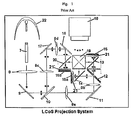
- the wire grid polarizer (WGP) based Liquid Crystal on Silicon (LCoS) microdisplay projection system (MDPS) [ C. Pentico, M. Newell and M. Greenberg, "Ultra high contrast color management system for projection displays," SID 03 Digest, pp. 130-133, 2003 ; also US patents, Kurtz et al, #6,585,378 and Pentico et al. #6,857,747 ] realizes both high resolution and high image contrast in comparison to other micro-display projection display technologies (such as transmissive Liquid Crystal Micro-Display (xLCD) and Digital Light Processor (DLP)) and direct-view display panels.
- WGP wire grid polarizer
- LCD Liquid Crystal on Silicon
- MDPS microdisplay projection system
- the lack of on-screen brightness is mitigated by the use of three microdisplay panels, one for each primary color band.
- An example of the WGP-based projection system is given in Fig. 1.
- the light from a high-pressure discharge lamp is homogenized by a long light rod (pipe).
- the light may also be preferentially polarized or have its unused portion recycled.
- a spatially uniform light distribution at the exit of the light pipe is imaged by a series of lenses, fold mirrors and dichroic band splitters to one or more LCoS panels (in a one-, two-, three- and four-panel polarization based MDPS).
- LCoS panels in a one-, two-, three- and four-panel polarization based MDPS.
- the primary function of the wire-grid polarizers is to separate the outgoing light beam from the incoming light beam [ D.
- the WGP is typically tilted at ⁇ 45° with respect to the principal direction of light propagation in a given LCoS panel illumination arm.
- the return light from each LCoS panel is then steered (deflected) to an orthogonal path, relative to the incoming illumination.
- the WGP also serves as a polarizing device.
- the WGP is a grid-polarizer, namely, it transmits a linear polarization aligned orthogonal to the direction of parallel micro-wires and reflects a complementary linear polarization parallel to the direction of the wires.
- the WGP When used in off-normal incidence, the WGP is configured as a high polarization-contrast mode if the transmitted linear polarization is contained in the plane of incidence (P-plane).
- P-plane plane of incidence
- this high contrast configuration requires the micro-wires to be oriented parallel to the S-plane (orthogonal to the plane of incidence with respect to the central ray).
- the wires are aligned perpendicular to the plane of drawing in Fig. 1.
- the MDPS Due to the trade-off between brightness and aperture of optical system (“Etendue”), the MDPS also requires the use of a moderate numerical aperture of each optical element. It is typical to configure the optical elements to function well with f/2.4 system (approximately ⁇ 12° in air incidence).
- the P- and S-plane of polarizations then refer to the linear polarization of the central ray in the cone bundle (hereafter term the principal ray) with respect to each local WGP element.
- the images displayed by LCoS panels 15, 15a and 15b are aggregated (converged) by an X-cube 19 and then projected to a large screen.
- Each color channel has an LCoS panel, a WGP, either tilted at +43°, or at -45°, as a beam splitter and polarizer/analyzer as well as a dedicated trim retarder compensator: 21, 21' and 21", each associated to panel 15, 15a and 15b, respectively.
- Each color channel also has its own pre-polarizer oriented to transmit P-polarization (one or more elements of WGPs or dichroic sheet polarizers oriented at normal incidence with respect to the principal ray; these are not shown in Fig. 1) and clean-up analyzer oriented to transmit S-polarization (one or more elements of WGPs or dichroic sheet polarizers oriented at normal incidence with respect to the principal ray; these are also not shown in Fig. 1).
- P-polarization one or more elements of WGPs or dichroic sheet polarizers oriented at normal incidence with respect to the principal ray; these are not shown in Fig. 1
- clean-up analyzer oriented to transmit S-polarization (one or more elements of WGPs or dichroic sheet polarizers oriented at normal incidence with respect to the principal ray; these are also not shown in Fig. 1).
- the trim retarder compensator is the crucial optical element in each color channel of the MDPS. It removes the residual LCoS panel retardance in the panel off-state [ D. Anderson and K. Shahzad, "Off-axis LCoS compensation for enhanced contrast," SID 03 Digest, pp. 1433-1435, 2003 ].
- the residual LCoS panel retardance can be categorized into in-plane (also A-plate) and out-of-plane (also C-plate) components.
- the term "retardance' refers to linear retardance magnitude unless stated otherwise. Linear retardance causes a phase difference to two orthogonal linear polarizations, aligned parallel to the extra-ordinary and ordinary axes of the linear retarder.
- A-plate retardance There is also a type of retardance called “circular retardance" which causes a relative phase difference of right- and left-handed circular polarized light. Normal incidence rays in the cone bundle see only the A-plate retardance, whereas off-axis rays (both oblique, i.e. non-normal but along the principal S- and P-planes; and skew, i.e. non-normal and incident away from the principal S- and P-planes) experience the C-plate retardance in addition to the A-plate retardance.
- A-plate retardance is noL seen at the trivial situation of 90° ray angle in the birefringent medium).
- the A-plate retardance of the compensator matches that of the LCoS panel in the off-state.
- the slow axes of both compensator and the LCoS panel are configured at orthogonal azimuthal offset (termed "crossed axes").
- the role of the fast/slow axes switches from the trim retarder compensator element to the LCoS panel element for normal incidence light.
- the light of a given linear polarization is alternately delayed more then less, or vice-versa in the two successive elements.
- the net effect is zero relative delay for the incoming polarization.
- the output polarization from the pair of trim retarder and panel in the off-state is unchanged versus their input polarization.
- This output light is then rejected by the combination of WGP and clean-up polarizer, whereby the high-reflection axis for the WGP and the high-transmission axis for the clean-up polarizer are at orthogonal orientation to the incoming polarization to the trim retarder and panel pair.
- the illumination for dark-state panel then does not appear on the screen.
- the introduction of the trim retarder as a compensator also does not alter significantly the throughput of the panel on-state. Hence the sequential contrast (full on/full off) is excellent.
- the A-plate retardance of both the LCoS and the compensator show a range of values due to manufacturing tolerances in device thickness and material birefringence control as well as operational drifts (temperature, mechanical stress etc). It is then typical to provide for a higher A-plate retardance in the compensator than the value of the nominal LCoS panel retardance [ J. Chen, M.G. Robinson and G.D. Sharp. "General methodology for LCoS panel compensation," SID 04, Digest, pp. 990-993. 2004 ].
- This mismatch in A-plate value requires offsetting of the optic axis of the compensator, relative to the nominal crossed axes configuration of trim retarder compensator/LCoS panel pair.
- the slow axis of the panel is typically configured substantially parallel to the bisector of the S- and P-planes (i.e., slow axis at ⁇ 45° and ⁇ 135° where the P-polarization is parallel to 0°/180° and S-polarization is parallel to ⁇ 90°).
- This configuration is crucial to utilizing the VAN-LCoS panel as an efficient electrically-controlled birefringence (ECB) device, with the crossed polarization conversion for this reflective device is given by:
- I(output crossed polarization) I(input linear polarization) * [sin( ⁇ nd / ⁇ )*sin(2 ⁇ )] 2 ,
- VAN-LCoS is typically configured as an approximate quarter-waveplate retarder in single pass (in the panel on-state) and its slow/fast axes approximately bisect the S- and P-polarization planes.
- the single channel description is part of a one or more panel WGP-based microdisplay projection systems.
- the pre-polarizer before the WGP and the clean-up polarizer after the WGP reflection is aligned non-tilted, with respect to the principal ray propagation direction.
- the pre-polarizer comprises one or more stages of substantially parallel elements of grid-based (reflective) polarizers (such as aluminum wire grid) or regular dichroic sheet (absorptive) polarizers.
- the clean-up polarizer comprises one or more stages of substantially parallel absorptive polarizer elements.
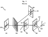
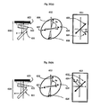
- FIG. 2 A schematic representation of the core optics 200 of either the red or the blue channel in Fig. 1 light engine is depicted in Fig. 2.
- the transmission axis of this polarizer 220 is substantially parallel to the transmission axis of the subsequent WGP element 202.
- This linear polarization direction is termed "P-polarization", with reference to the principal ray and the conical mount of the WGP element.
- the WGP element is said to have been rotated at +45° about the +Y-axis and with respect to the +Z-axis (or simply tilted at +45° w.r.t. Z-axis). This adheres to the convention of Euler angle rotation with a Right-Handed XYZ coordinate system (RH-XYZ).
- the core optics of the green channel (not shown) has the WGP tilted at -45° w.r.t. Z-axis and the return pass to the WGP being steered towards a clean-up polarizer positioned at the reflected port of WGP in return pass.
- the micro-wires on the surface of the WGP element 202 are aligned parallel to the Y-axis in the drawing.
- the wires are located on the rear-side of the WGP substrate (away from the input) such that the linear polarized light is less affected by the thermal and mechanical stress-induced birefringence in the substrate.
- the beam is analyzed by the WGP element.
- the orthogonal polarization, S-polarization, as reflected by the wire-side of the WGP element is deflected towards the clean-up polarizer 205, having a transmission axis orthogonal to the pre-polarizer.
- the analyzer polarization is shown as 221. This reflected light does not pass through the WGP substrate and hence is less affected by the induced birefringence in the substrate.
- the LCoS panel has been shown with its slow-axis (SA) 230 located in the first quadrant of a RH-XYZ coordinate system, while looking at the beam coming to the observer in the first pass (RH-XYZ).
- SA slow-axis
- RH-XYZ first pass
- SA slow-axis
- the LCoS SA is given by the azimuthal angle 235, counter-clockwise (CCW) from the X-axis being positive angles.
- the fast-axis (FA) of the VAN-LCoS panel is defined as being orthogonal to the SA orientation (i.e., ⁇ 90° azimuthal offset to SA).
- This FA 231 is shown as being located in quadrant 2 and 4, at +135°/-45° azimuthal angles from the X-axis.
- the trim retarder compensator 203 in the case of higher-value retardance has to be rotated or clocked to orient its SA in the quadrant neighboring the LCoS SA, so that the two sets of slow axes are not crossed.
- An example of a generic trim retarder compensator is shown as element 203 with its slow-axis 240 oriented at the azimuthal angle 245.
- the trim retarder compensator SA can typically deviate up to 30° from the closest S- or P-axis, although a deviation of less than 15° is preferable.
- SA and FA when used for both VAN-LCoS panels and trim retarder compensators here refer to the two orthogonal birefringent axes when the linear retardance is measured at normal incidence.
- the SA and FA orientations changc with off-axis illuminations, as well as reversing of SA/FA roles for a negative out-of-plane retardance component at a sufficiently large angle of incidence.
- the optimal trim retarder compensator incorporates an A-plate element and a -C-plate element (out-of-plane retardance with negative sign of birefringence).
- This trim retarder compensator is aligned substantially parallel to the LCoS X-Y plane.
- the requirements for a good trim retarder compensator device are well known [see for example K. Tan et al., "Design and characterization of a compensator for high contrast LCoS projection systems," SID 2005, p. 1810, 2005 ].
- liquid crystal mixture crossed linked into a polymer host has been shown to be more versatile in terms of reliability, uniformity and ease of targeting retardance values [ Zieba et al. US Patent Application Publ. No. 20050128380 ].
- the LCP layer is integrated with inorganic thin-films to realize the -C-plate components [ Tan et al, US Patent Application Publ. No. 20050128391 ].
- the full function trim retarder compensator has been shown to provide compensation for excellent contrast as well as being environmentally stable [ M. Duelli et al., "High performance contrast enhancing films for VAN-mode LCoS panels," SID 05 Digest, p. 892,2005 ].
- the invention disclosed here employs a form birefringent film tilted at an angle to compensate the retardance of a reflective LCoS or transmissive LC device in the dark-state resulting in significant improvement in contrast.
- the birefringent film has a uniaxial indicatrix and it is configured with its C-axis parallel to the device normal.
- a C-plate-only retarder is a birefringent element where the axis of optical symmetry lies along the device normal of a substantially parallel plate.
- a C-plate retarder does not present any net retardation for normal-incidence rays.
- extra-ordinary rays (e-wave) the effective index of refraction can be higher or lower value than the index value of the orthogonal, ordinary ray (o-wave) polarization. This means the C-plate can possess either a positive C or a negative C retardance.
- C-plate-only retarder at a tilted alignment is advantageous for substantially reducing the retarder cost by reducing the number of elements in the optical system as well as simplifying assembly.
- This invention relates to the use of a C-plate retardance compensator to enhance the image contrast of transmissive as well as reflective liquid crystal displays and display systems. Improved residual retardance compensation is achieved by introducing a small tilt angle to the compensator with respect to the system X-Y-plane as well as choosing an appropriate rotation angle of the tilted plate about the Z-axis in relation to the display panel slow axis.
- FIG 1 is a schematic diagram of the prior art Ultrex-3 3-panel Wire-grid Polarizer (WGP) based Liquid Crystal on Silicon (LCoS) projection light engine.
- WGP Wire-grid Polarizer
- LCDoS Liquid Crystal on Silicon
- FIG. 2 illustrates a prior art subsystem of wire grid polarizer (WGP) based light engine including an LCOS panel, WGP, trim retarder compensator, and pre- and post-polarizers.
- WGP wire grid polarizer
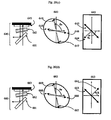
- FIG 3 illustrates an embodiment of a subsystem of wire grid polarizer (WGP) based reflective light engine including an LCOS panel, WGP, a tilted C-plate-only retarder compensator, and pre- and post-polarizers.
- WGP wire grid polarizer
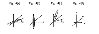
- Figures 4 defines the uniaxial birefringent indicatrix configurations used: (a) A-plate, (b) C-plate and (c) O-plate for the given XYZ coordinate system in (d) where the device plane is parallel to the XY plane and the Z-axis is parallel to the device normal.
- Figure 5 shows the relation of effective fast/slow axes of a tilted C-plate where the C-plate birefringence is negative (a) and positive (b).
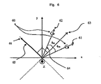
- Figure 6 shows the relative azimuthal angles between the LCoS fast/slow axes and axis of rotation for the tilted -C-plate, where tilted C-plate retarder compensator has an on-axis retardance greater than or equal to the LCoS A-plate retardance.
- Figure 7 shows the relative azimuthal angles between the LCoS fast/slow axes and axis of rotation for the tilted ⁇ C-plate, where tilted C-plate retarder compensator has an on-axis retardance smaller than the LCoS A-plate retardance.
- Figures 8 is a graph of the measured and design net retardance of a dielectric -C-plate retarder at a range of angles of incidence in air.
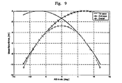
- Figure 9 is a graph of the calculated first, second and overall double-pass net retardance along the tilt-plane of a tilted -C-plate element.
- VAN vertically-aligned nematic
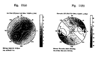
- Figure 11 is a contour plot of the calculated conoscopic net retardance and slow axis maps of a - 110nm C-plate-only retarder, tilted at 7deg about 45 deg. axis of rotation.
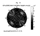
- Figure 12 is a contour plot of the simulated double-pass leakage intensity of cascading a tilted FBAR -C-plate to at 7° tilt, about an axis of rotation at 135° and a VAN-mode LCoS panel.
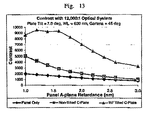
- Figure 13 is a plot of the simulated contrast performance of a 7° tilted FBAR ⁇ C-plate and a non-tilted FBAR ⁇ C-plate for a range of LCoS A-plate retardance values.
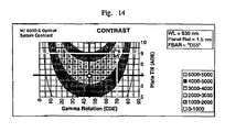
- Figures 14 is a contour plot of the simulated tolerance of a tilted FBAR -C-plate with the variation of axis of rotation and the polar angle tilt.
- Figure 15 is a schematic of a +C or -C-plate retarder, sandwiched between two wedged prisms of suitable indices so as to produce a compensator element aligned plane-parallel to the LCoS device.
- the effective axis of rotation of the C-plate retarder element within the laminate must not be parallel of either the P-polarization or the S-polarization of WGP.
- Figure 16 is a schematic of a +C-plate retarder, sandwiched between two wedged prisms of suitable indices so as to produce a compensator element aligned plane-parallel to the LCoS device.
- One or both external surfaces are applied with a -C-plate FBAR coating to provide for an overall net -C-retardance.
- the effective axis of rotation of the C-plate retarder element within the laminate must not be parallel of either the P-polarization or the S-polarization of WGP.
- Figure 17 illustrates a transmissive microdisplay projection system, where one or more of tilted - C-plate is positioned between the incident-side polarizer and the exit crossed-polarization analyzer so as to substantially compensate for the display element retardance for on-axis and off-axis rays.
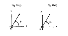
- Figure 18 (a) defines the right-handed XYZ coordinate system, when viewing the beam coming to the observer, along with Counter-clockwise (CCW) convention for positive azimuthal angles (termed “RH-XYZ”)
- Figure 18(b) defines the left-handed XYZ coordinate system, when viewing the beam away from the observer, along with counter-clockwise (CCW) convention for positive azimuthal angles (termed “LH-XYZ”)
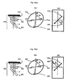
- Figure 19 is a schematic diagram showing the relative alignment of trim retarder slow axis at each local contrast maximum and the fast/slow axes of for different panel orientations with the WGP tilted at -45°.
- Figure 20 is a schematic diagram showing the relative alignment of trim retarder slow axis at each local contrast maximum and the fast/slow axes of for different panel orientations with the WGP tilted at +45°.
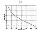
- Figure 21 is a graph of an experimental net retardance spectrum of a ⁇ C-plate retarder tilted at approximately 20° with respect to the principal ray.
- Figure 22 is a contour plot of an experimental net retardance map of a -C-plate retarder tilted at approximately 20° with respect to the X-Y plane.
- the axis of rotation in effecting the out-of-plane tilt and the resultant slow-axis of the tilted ⁇ C-plate retarder is oriented at approximately 20° CCW in a RH-XYZ coordinate system.
- the convergent viewing cone extends to ⁇ 20° polar angles along all azimuthal planes.
- the preferred embodiment of this invention is illustrated by the example in Fig. 3.
- the cone of light output from the prior stage light pipe or other homogenizer such as Fly's Eye Array
- the transmission axis of this polarizer 320 is substantially parallel to the transmission axis of the subsequent WGP element 302: this is the P-polarization axis.
- the WGP element is tilted at polar angle 310, at approximately +45° w.r.t. Z-axis.
- the beam is analyzed by the WOP element 302.
- the orthogonal polarization, S-polarization, as reflected by the wire-side of the WGP element is deflected towards the clean-up polarizer 305, having a transmission axis orthogonal to the pre-polarizer.
- the analyzer polarization is shown as 321.
- Optical element 303 differs from prior-art retarder compensator in several key aspects.
- Optical element 303 is configured as a C-plate retarder, as opposed to the more typical A/-C-plate retarder, A-plate-only retarder or biaxial retarder 203 in prior art optical system 200.
- the C-plate retarder element 303 is aligned with its device plane being non-parallel to the device plane of LCoS 304 whereas the parallel alignment is typically found in the corresponding retarder compensator 203 and LCoS 204 in prior art optical system 200.
- C-plate retarder compensator 303 is aligned at a polar angle tilt 311 versus the system X-axis and at a polar angle tilt 312 versus the system Y-axis.
- This two-dimensional tilt gives rise to an axis of rotation 340, oriented at an azimuthal angle 345, w.r.t. X-axis.
- the axis of rotation 340 is parallel to the LCoS device plane (also the system X-Y-plane) and the Z-axis is the propagation axis of the principal ray w.r.t. the first pass.
- the axis of rotation spans 0 to 360°, in order to distinguish forward vs. backward tilting.
- the tilted C-plate retarder compensator in this invention must be tilted in two dimensions, according to the XYZ coordinate system shown here. This means the effective fast- and slow-axis of the tilted C-plate must not align to the system S- or P-polarization axis in core optical system 300, i.e., ⁇ ax ⁇ 0°, ⁇ ax ⁇ ⁇ 90° and ⁇ ax ⁇ 180°.
- the polar angle tilt, ⁇ t of the C-plate retarder compensator can range from 0.1° to 45°, preferably, 0.1° to 30° and more preferably 0.1° to 15°.
- the polar angle tilt refers to the magnitude of the out-of-plane tilt, positive and negative polar angles (forward tilt toward and backward tilt from the LCoS plane, respectively) are determined by the axis of rotation.
- the polar angle tilt is set to produce a suitable amount of net retardance taking into consideration the designed C-plate retardance, the additional Z-axis space requirement and the acceptable image impairment resulting from parallax introduced by the tilted plate.
- the C-plate retarder compensator when used at normal-incidence does noL have fast/slow axes as the residual net retardance is very low, being mostly contributed by the induced birefringence in the substrate.
- the compensator utilizes a -C-plate retarder.
- the nominal rotational axis of the tilted -C-plate is oriented parallel to the fast axis of the LCoS panel (typically ⁇ 45° azimuthal angle with respect to the plane-of-incidence, P-plane of the WGP).
- the net retardance in nanometer units is given by,
- ⁇ o ⁇ n o 1 ⁇ sin 2 ⁇ n o 2 ;
- n e and n o are the extraordinary and ordinary indices, respectively, for an incidence ray at wavelength ⁇ ; the light is incident in air at ⁇ polar angle w.r.t.
- C-plate device normal and d TR is the C-plate retarder thickness in nanometer units.
- the net retardance has a positive sign for +C-plate and a negative sign for -C-plate retarder.
- Fig. 4(a) The optical symmetry for a uniaxial birefringent medium is illustrated in Fig. 4.
- Fig. 4(a) an A-plate retarder element is sketched whereby the optic axis is aligned parallel to the device plane (X-Y-plane).
- the device normal is parallel to the Z-axis. It's assumed that X and Y dimensions of the part are much larger than the thickness dimension along Z-axis.
- the C-plate symmetry is illustrated in Fig. 4(b).
- the optic axis is aligned parallel to the device normal. It's noted that a positive uniaxial birefringence has been sketched, where the extraordinary (e-) index is greater than the ordinary (o-) index and the e-wave direction is pointed along the Z-axis.
- the index indicatrix is "disc” like, with its e-wave direction again pointed along the Z-axis.
- O-plate oblique symmetry
- This configuration has an in-plane (also termed A-plate) retardance, with its fast/slow axes oriented parallel and perpendicular to the projection onto X-Y plane.
- the out-of-plane (also termed C-plate) component is also present for a general O-plate retarder element.
- the device X-, Y- and Z-directions are as indicated by the arrows in Fig. 4(d).
- a ⁇ C-plate 55 is tilted out-of-plane about a rotation axis 51, oriented at an azimuthal angle 54 ( ⁇ ax ) with respect to the X-axis.
- the axis of rotation 51 lies parallel to the X-Y plane. After the tilting, this axis is the effective slow-axis for principal ray in optical system 300.
- the fast-axis 50 of this tilted ⁇ C-plate lies on the tilted surface at ⁇ 90° offset from the slow-axis.
- the ideal scenario involves matching the effective on-axis retardance of the compensator to that of LCoS A-plate retardance (termed "matched-value-compensation").
- the fast/slow axes sets of the retarder and the LCoS are at crosscd-axes as alluded to in prior-art.
- the axis of rotation also the compensator slow-axis
- the axis of rotation is aligned substantially parallel to the LCoS fast-axis if the polar angle is adjusted to produce the same amount of retardance in the tilted ⁇ C-plate as in the LCoS A-plate.
- a high yield LCoS engine assembly will require setting the compensator on-axis retardance at a higher value than the LCoS A-plate retardance and relying on over-clocking of the relative azimuthal angles (LCoS and retarder) to optimize the image contrast performance.
- the axis of rotation for the tilted C-plate-only compensator is not required to be substantially aligned parallel or orthogonal to the fast axis of the LCoS panel.
- the slow-axis of the tilted ⁇ C-plate-only element (also the axis of rotation) can be 'over-clocked' away from the LCoS Fast-axis if the magnitude of the tilted C-plate on-axis net retardance is greater than the LCoS A-plate retardance.
- the over-clocking angle i.e., azimuthal offset angle from the bisector of the S- and P-polarization axes
- ⁇ LC is the LCoS A-plate retardance
- ⁇ TR is the on-axis retardance of the tilted C-plate element as seen by the principal ray
- ⁇ TR ⁇ ⁇ LC is the LCoS A-plate retardance
- the example in Fig. 6 has the LCoS slow-axis 66 aligned at 135° azimuthal angle.
- the tilted -C-plate is adjusted for a suitable polar angle tilt 60, where a matched C-plate retarder on-axis retardance and LCoS A-plate retardance is realized, the axis of rotation can be anchored at +45° azimuthal angle 63.
- the polar angle tilt is made larger than the nominal case.
- the axis of rotation now deviates from the bisector of Sand P-polarization axis by ⁇ ob , giving four local optima orientations, two of which are shown as 61 and 62.
- a better compensation result can be obtained by choosing the azimuthal offset, where the resultant compensator slow-axis is oriented nearer to the P-polarization than the S-polarization of the WGP.
- the solution space of arbitrary LCoS slow axis orientation over all four quadrants (specifically referring to the positive-tilt of the VAN-mode imager LC tilt) is given in Table 1.
- the LCoS slow axis is nominally aligned at the bisector of the S- and P-plane in the optical system with an azimuthal angle tolerance of ⁇ , where 8 can be ⁇ 20°, more preferably ⁇ 10° and still more preferably ⁇ 5°.
- This tolerance angle has a small impact on the predicted azimuthal offset by equation (4); it's a cos 2 (2 ⁇ ) modification of LCoS A-plate retardance where the function is rather insensitive at small angles.
- the two preferred axis of rotation may not produce equal contrast results; one of the these two preferred solution may be best for pairing up with both cases +45° and -45° WGP tilt (in different color channels of the multiple-panel light engine).
- Table 1 Orientation solution space of LCoS versus tilted -C-plate retarder compensator. LCoS orientation Tilted ⁇ C-plate orientation Quadrant number Approx. slow-axis, ⁇ LC ⁇ ⁇ Quadrant number Approx.
- axis of rotation Preferred solution Approx. axis of rotation: Secondary solution 1 45° ⁇ ⁇ 2 and 4 135° ⁇ ⁇ ax ⁇ 180°, 90° ⁇ ⁇ ax ⁇ 135°, 315° ⁇ ax ⁇ 360° 270° ⁇ ax ⁇ 315° 2 135° ⁇ 1 and 3 0° ⁇ ax ⁇ 45°, 180° ⁇ ⁇ ax ⁇ 225° 45° ⁇ ax ⁇ 90°, 225° ⁇ ax ⁇ 270° 3 225° ⁇ 2 and 4 135° ⁇ ax ⁇ 180°, 315° ⁇ ax ⁇ 360° 90° ⁇ ax ⁇ 135°, 270° ⁇ ax ⁇ 315° 4 315°° ⁇ 1 and 3 0° ⁇ ⁇ ax ⁇ 45°, 180° ⁇ ax ⁇ 225° 45° ⁇ ax ⁇ 90°, 225° ⁇ ax ⁇ 270°
- the axis of rotation of the tilted -C-plate compensator may be fixed at ⁇ 45°, in the same quadrant as the fast axis of the LCoS element, provided that the tilt angle is controlled such that a smaller on-axis retardance is produced by the tilt, relative to the A-plate retardance of the LCoS panel.
- This is term "under-value-compensation" scheme; due to the relative azimuthal clocking, the compensation produces an overall net retardance near zero for light traversing the two stages.
- the relative azimuthal angles of this compensation scheme are illustrated in Fig. 7.
- the residual retardance ⁇ LC of the LCoS panel 75 is used to compensate for the-C-plate on-axis retardance ⁇ TR 74.
- the LCoS slow axis 76 and fast axis 73 are typically very close to the ⁇ 45° azimuth with respect to the PBS P-plane, for an effective electrically controlled birefringence (ECB) LC device has to be created by driving a voltage through the LCoS cell in gray states.
- EAB electrically controlled birefringence
- the LCoS fabrication process often results in a small deviation 72 ( ⁇ ob ) of the slow/fast axes from the ideal 'S' and 'P' bisector alignment (say, up to ⁇ 10°).
- the out-of-plane tilting 70 of the -C-plate retarder is effected about a rotation axis 71, aligned substantially bisecting the S- and P-planes.
- the tilt angle can be reduced due to the smaller on-axis retardance requirement. This can result in some space saving as well as reduced image quality impairment due to the use of a tilted optical element.
- the on-axis retardance of the tilted ⁇ C-plate is related to the LCoS axis offset and LCoS A-plate retardance by the following approximate expression,
- ⁇ TR and ⁇ LC are as defined before but, ⁇ TR ⁇ ⁇ LC .
- the birefringent compensator may also be a +C-plate retarder, whose rotational axis for effecting the tilt would then be oriented substantially parallel to the slow axis of the panel, in the case of matched-value compensation. This is because the axis of rotation becomes the fast-axis of the tilted +C-plate retarder.
- the axis of rotation for +C-plate is nearer to the S-polarization than to the P-polarization in order that the resultant slow-axis of the tilted +C-plate is aligned closer to the P-plane of WGP.
- Table 2 The general cases of over-value-compensation with a +C-plate retarder at a tilt angle are listed in Table 2.
- the two preferred solutions may not produce equal contrast results, one of which may be better than the other depending on the alignment of the WGP.
- the scenario of under-value-compensation is not shown here for using a +C-plate retarder compensator.
- the axis of rotation and the LCoS slow-axis are oriented in the same quadrant.
- Table 2 Orientation solution space of LCoS versus tilted +C-plate retarder compensator.
- the C-plate retarder is made with form birefringent antireflection (FBAR) coatings on a transparent substrate.
- FBAR birefringent antireflection
- the dielectric coated -C-plates utilize a series of alternating thin layers of two or more different index materials and the resultant dielectric stack produces low reflectance as required by reflection geometry of an LCoS engine.
- the on-axis and off-axis net retardance of the tilted ⁇ C-plate is realized as illustrated in Fig. 9.
- the simulation assumes that this -C-plate retarder is mounted at 7° off-normal geometry.
- the net retardance for the principal ray doubles on second pass.
- the first pass incidences are impinged on the tilted plate at a higher AOI than the tilt angle and the net retardance magnitude is considerable larger than the net retardance of the principal ray.
- these rays are folded to the opposite azimuth of the tilted -C-plate such that the second pass AOI and hence the net retardance values are reduced versus the first pass. Similar double-pass folding occurs for negative AOI rays in the first pass.
- the result is a self-mirrored, symmetric retardance profile, with respect to the axis of rotation.
- the plot in Fig. 9 shows the net retardance profile along a single plane of incidence (corresponding to plane of tilt of -C-plate retarder).
- the net retardance of the LCoS device changes as a function of the polar and azimuthal viewing angles.
- the associated slow/fast axes also vary as a function of the viewing angles.
- the tilted -C-plate designed with an appropriate -C retardance and tilted suitably to induce an appropriate amount of on-axis retardance, matches the LCoS net retardance for every ray angle.
- the slow-axis of the double-passed tilted ⁇ C-plate is substantially orthogonal to the slow axis of the LCoS device.
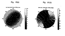
- the slow-axis at normal incidence ray is orientated at approx. -45° w.r.t. reflection viewing (as shown in Fig. 10 (b) or +45° w.r.t. transmission viewing).
- the axis of rotation for the FBAR ⁇ C-plate which is also its slow-axis w.r.t. to the principal ray, has to be aligned at 135° w.r.t. transmission viewing in RH-XYZ coordinate set.
- the corresponding net retardance and the retarder slow axis orientations of the 7° tilted FBAR -C-plate are shown in Fig. 11 (a) and (b), respectively.
- the fuzziness in the plots are an artifact of sampling the viewing cone one plane of incidence at a time and converting the data to a rectangle sample grid for plotting and coneweighted contrast computation.
- the retardance profile of the tilted FBAR -C-plate matches that of LCoS closely.
- the slow-orientation of the FBAR ⁇ C-plate has a nominal 45° w.r.t. reflection viewing (as shown in Fig. 11(b) or -45° w.r.t.
- the C-plate-only compensator is tilted at an angle with respect to the LCoS panel.
- the tilt of the plate introduces net retardance, as seen by the principal ray, in an amount which corrects for the residual A-plate retardance of the LCoS panel.
- the form birefringent coating on the -C-plate still provides for appropriate C-plate correction for the off-axis performance. This arrangement allows a single -C-plate-only component to provide for both on-axis and off-axis LCoS retardance compensation to achieve a high contrast image.
- Theoretical modeling and empirical measurements have confirmed that this configuration results in high contrast.
- the plot shown in Fig. 13 is the theoretical calculation which shows expected contrast ratio as a function of display panel A-plane retardance. While non-tilted C-plate compensation is adequate for very small LCoS A-plate retardance (e.g. ⁇ 0.5nm), the calculated results show that a significant increase in contrast can be obtained by aligning the C-plat at a tilt for common LCoS A-plate retardance values (up to 2nm). In this model, the rotational axis is fixed at 45°, and the tilt angle is also fixed at 7° out of plane.
- the -C-plate FBAR coating design has -110nm C-plate retardance at 630nm wavelength.
- the on-axis retardance at 7° tilt is approximately 1.4nm. Consequently, only LCoS panels with residual A-plate retardance ⁇ 1.4nm are compensated exactly. However it can be seen from the analysis that a large range of panel retardance can be compensated significantly with a single compensator at a fixed tilt angle.
- A-plate retardance For panels with much higher or lower A-plate retardance (e.g. greater than 2.5 nm or less than 0.5 nm), either the tilt has to be adjusted, the axis of rotation has to be varied, the value of the -C-plate has to be adjusted, or a combination of all three.
- a fixed value compensator plate can be tuned to match panel retardance by either tilting the compensator plate and/or by rotation (i.e., clocking) when the net retardance of the -C-plate over-compensates the A-plate retardance of the LC device.
- Fig. 14 The numerical tolerance results of pairing an FBAR -C-plate at a slight tilt to an VAN-mode LCoS are given in Fig. 14.
- the figure shows the contrast variations as a function of-C-plate compensator out-of-plane tilt and axis of rotation change.
- Over-value compensation of LCoS panels can be optimized at a fixed tilt angle by adjusting the rotation of the plate.
- high contrast can be achieved with the plate tilt at 7° and rotation at 45° (aligned with fast axis of LCoS panel).
- High contrast can also be achieved at a 9° plate tilt with a ⁇ 25° rotation from parallel alignment with the LCoS fast axis.
- the optimal rotation axis at approx. 20° is likely to give better contrast.
- the WGP-PBS is modeled as a leaky polarizer with about 450:1 transmitted polarization contrast and 30:1 reflected polarization contrast.
- the pre-polarizer and clean-up analyzer are modeled as 1000:1 polarization contrast elements used at normal incidence to the cone axis. Under these ideal conditions, there is negligible difference between the contrast numbers at each of the four local contrast maxima (two orientations of the tilted C-plate axis of rotation located in each of the two neighboring quadrants) for a given LCoS slow-axis alignment. In the actual optical systems, the WGP is either aligned at -45° or +45° w.r.t.
- All the azimuthal angles used here are referenced to the RH-XYZ coordinate system.
- the RH-XYZ coordinate system is referenced to the incidence; when viewing the transmitted field, RH-XYZ coordinate system is referenced to the transmitted beam; when viewing the reflected or double-pass transmission field, the RH-XYZ coordinate system is referenced to the returned beam.
- the coordinate sets in the transmitted and incident sides are consistent to each other but the coordinate set in the reflected side has a left-right mirror property versus the incident coordinate set.
- the sign of circular eigenpolarization is used consistently in the incident, transmitted and reflected sides.
- the RH-XYZ coordinate system is shown in Fig. 18(a).
- the coordinate axes represent the RH-XYZ when specifying the Euler angles (two angles for uniaxial medium and three angles for biaxial medium) w.r.t. to viewing the incident beam head-on.
- polar and azimuthal angles of each uniaxial layer are represented by ( ⁇ c , ⁇ c ).
- the RH-XYZ system is maintained by reversing the direction of the X-axis.
- the RH-XYZ coordinate set for reflection viewing is equivalent to a LH-XYZ coordinate set as referenced to the incident beam (i.e., viewing the back of the incidence). This is shown in Fig. 18(b).
- the azimuthal angle is defined positive for Counter Clockwise (CCW) rotation from the positive X-axis. This axis orientation is used for example to describe the fast/slow axes of a retarder.
- the transmitted viewing plane is aligned to the plane of incidence.
- the viewing plane has a 180° offset from the plane of incidence (for a 360° azimuthal plane range and a 0 to 90° polar angle range).
- Fig. 19(a) - (d) all possible configurations of the tilted ⁇ C-plate retarder compensator and LCoS orientations are represented in Fig. 19(a) - (d) for the case of the WGP being oriented at -45° w.r.t. Z-axis.
- the optical system configurations are named 500, 520, 540 and 560. These correspond to the LCoS SA being oriented at quadrant 3 ( 504 ) , 1 (524), 4 (544) and 2 (564), respectively, as referenced to LH-XYZ coordinate system.
- the SA orientations of the panels are assumed substantially bisecting the system S- and P-polarization directions (for example within ⁇ 10° of bisector).
- the SA of the tilted C-plate corresponds to the axis of rotation to effect the out-of-plane tilt. This axis lies in the plane of X-Y.
- Configurations 600, 620, 640 and 660 are mirror images (about the y-axis) of configurations 500, 520, 540 and 560, respectively.
- the LCoS panel SA orientations of configurations 600, 620, 640 and 660 are located at quadrants 4 (604), 2 (624), 3 (644) and 1 (664), respectively.
- orientations as indicated actually mean that the optic-axis of LCoS device is tilted towards the +Z direction, w.r.t. RH-XYZ coordinate system.
- the tilt-plane of the tilted -C-plate retarder compensator is at a further 90° CCW from the axis of rotation and this tilt plane leans forward to the +Z axis.
- the ⁇ C-plate retarder was tilted at about 20° polar angle.
- the design targets -195nm C-glate retardance single-pass.
- the net retardance dispersion is shown in Fig. 21.
- the single-pass net retardance map at a cone of up to 20°, over 0 to 360° viewing planes is illustrated in Fig. 22.
- the experimental contrast results have been collected with a PR-705 radiometer.
- the experimental results for configurations 600, 620. 640 and 660 are derived from configurations 500s, taking into account the symmetry in the optical setup. These contrast results are tabulated in Table 4.
- the corresponding panel contrast ratios without the trim retarder compensator range from 1200:1 to 2300:1 in the Green color channel for optical contigurations 500s and 600s.
- Table 3 Experimental Contrast measurement results in the green-band for optical configurations in series 500s.
- optimal picking of any one or more of the four solutions of tilted -C-plate slow-axis entails.
- the display system vendor intends to keep the flexibility of aligning to both orientations of the WGP in each color band and there is only one LCoS slow-axis selected.
- the axis of rotation for the tilted -C-plate retarder is optimal when it is aligned closest to the P-polarization axis.
- the slow-axis of the retarder compensator is substantially parallel to the P-pol. axis for a large mismatch of retarder net retardance and the LCoS A-plate retardance, both referenced to the principal ray.
- the optimal alignment space for the axis of rotation for the tilted ⁇ C-plate within 1/8 of circle in each local optima is listed in Table 5 for all eight optical configurations grouped into four categories depending on the LCoS SA orientation.
- Table 5 Azimuthal angle range for optimal compensation of a VAN-LCoS panel cascaded with an tilted ⁇ C-plate retarder compensator, where each azimuthal angle range is nearly 45° extended from the closest P-polarization axis. A nominal 0.1 degree offset from the S- and P-polarization bisector has been quoted.
- the selections will come from within series 500s and 600s.
- the optimal slow-axis location of the tilted -C-plate can be selected from configurations 500 and 540. From the experimental contrast entries in Table 3, orientations 507 and 546, providing 6400:1 and 6800:1 contrast respectively are the optimal picks for configurations 500 and 540, respectively.
- Yet another scenario may involve boosting the contrast at the weakest-contrast channel (typically blue channel) and traded off contrast at the more optimal contrast channels (typically green and red channels) for an overall non-colored dark state.
- the contrast in the blue channel is typically worst because of the substantially poorer performing optics, especially the crossed polarizers and the WGP elements.
- the -C-plate retarder meant for the blue channel will be rotated about an axis substantially parallel to the S-polarization, pointing vertically up for the optical configurations 500s and pointing vertically down for the optical configurations 600s, whereas the axis of rotations for green and red channels will be aligned substantially parallel to the P-polarizations (two choices per optical configuration).
- the non-equal contrast performance with respect to the alignment of the -C-plate axis of rotation is a result of the birefringence in the WGP element. Whilst a complete numerical model is the ultimate goal, quick experimental verification of the solution space can be more readily done. The errors and repeatability of these contrast numbers are about ⁇ 200 points for a nominal of 5000:1 1 contrast value, i.e., ⁇ 4%. The relative contrast values, as a function of the slow-axis of the tilted ⁇ C-plate that have been observed are significantly beyond this tolerance.
- inventions may include the use of inorganic birefringent crystals, cut to a C-plate.
- the C-plate-only retarder is utilized in such a way to also realize a suitable amount of net retardance in the plane of a microdisplay imager as well as providing a suitable amount of out-of-plane retardance.
- This tilted crystal C-plate functions much the same as a Berek compensator.
- the required plate thickness will be in the range of tens of microns, in order to deliver approximately 200 to 500nm of -C plate retardance.
- Another embodiment of this invention seeks to sandwich the C-plate plate 150 (for example an FBAR coated plate or a crystal plate) between wedged substrates.
- This embodiment is shown in Fig. 15.
- the outer surfaces 153 of sandwiched element are substantially parallel and AR-coated, and the retarder assembly is aligned substantially parallel to the LCoS stage 154. This reduces image quality impairment due to parallax in the first pass beam 151 and the second pass beam 152.
- the on-axis retardance in this case is induced by having non-zero angle of incidence of the principal ray, with respect to the sandwiched C-plate.
- Both +C and -C plate can be utilized in this manner, but only the -C-plate is able to simultaneously compensate for the in-plane and out-of-plane retardance of the LCoS dark state.
- the on-axis performance of the tilted +C-plate can be made as good as the tilted -C-plate compensated LCoS.
- the off-axis rays will see an even larger net retardance than the LCoS panel alone.
- This +C-plate configuration is only useful for a very limited cone incidence angle.
- a further embodiment, shown in Fig. 16, uses a tilted +C-plate 160 embedded between wedged substrates to correct for the residual A-plate retardance, and a -C-plate on the normal incidence exterior surface(s) 163 to correct for C-plate retardance in the LC panel 164.
- the first pass beam and the second pass beam are indicated by 161 and 162 respectively.
- a retarder element tilt and non-tilted with its slow/fast axes aligned parallel to the display system S- and P-plane has its on-axis retardation effect negated by the absence of two modes of beam propagation.
- the tilted plate compensator is also suitable for transmissive microdisplay projection system.
- the tilted -C-plate retarder produces both on-axis retardance and off-axis retardance from a single element.
- the on-axis retardance can be used to cancel out the residual A-plate retardance of a transmissive display panel, such as TN-mode LCD and VAN-mode LCD. It is noted that the transmissive panels are approx. twice as thick in its LC layer and hence the amount of on-axis retardance required of the tilted C-plate is significantly larger.
- Both the imager panel and the tilted -C-plate compensator when used in single pass transmission, are likely to face issues of asymmetric retardance profile vs. cone angles.
- the small amount of circular retardance in panel off-state is not compensated by a liner retarder such as a tilted -C-plate.
- FIG. 17 An embodiment of this invention, incorporating a tilted C-plate in a transmissive optical system, is illustrated in Fig. 17.
- the cone of light output from the prior stage light pipe or other homogenizer such as Fly's Eye Array
- the transmission axis of this polarizer 420 can be aligned arbitrarily over the entire circle, more commonly at ⁇ 45°, 0° or 90°.
- the illustration uses a 0° polarization incidence 420.
- the light passing the pre-polarizer is impinged onto a transmissive LCD imager 404.
- the imager has its slow axis 430 aligned at ⁇ 45° azimuthal offset 435 versus the pre-polarizer transmission axis. This light then exits the system via a post-analyzer 405, with its transmission axis 421 aligned perpendicular to the pre-polarizer axis 420.
- One or more stages of trim retarder compensator 403 is inserted between the pre-polarizer 401 and the post-analyzer 405.
- the trim retarder element can be aligned before the imager or after the imager or both. At least one of the trim retarder element utilizes a C-plate-only retarder mounted at a tilt. This tilted element is shown in the optical system 400 positioned before the imager.
- the combined non-zero tilts of 411 and 412 sets the rotation axis at 440 azimuth.
- the associated angle 445 nominally perpendicular to the imager slow-axis 435; or a tilted +C-plate retarder, the associated angle 445 nominally parallel to the imager slow-axis 435.
- a common practice in retardation compensation is to over-clock the C-plate retarder slow-axis from parallel or perpendicular alignment to the imager slow-axis by implement an over-value compensation scheme.
- the tilt of the -C-plate has to be effected such that the light rays at the tilted -C-plate, along a given azimuthal plane of the cone incidence that see a larger AOI than the principal ray, also experience a larger angular difference with respect to the extraordinary axis (e-wave) of the positive uniaxial VAN-LC material.
- a single-pass transmissive system will result in some azimuthal dependence in the compensation efficacy. The requirement above helps to mitigate the undesirable effects of having a tilted ⁇ C-plate retarder and an oblique LC alignment.
- the transmissive panel is a twisted-nematic (TN) imager, where the total twist angle is less than or equal to approximately 90 degrees
- the tilt of the -C-plate retarder has to be effected about an axis of rotation that is substantially orthogonal to the bisector of the TN twist angle range.
- the magnitude of the tilted C-plate retardance and the size of the polar angle tilt have to be adjusted such that the asymmetry of conoscopic net retardance maps of the tilted ⁇ C-plate retarder and the TN cell are well matched.
- a single-pass transmissive system will result in some azimuthal dependence in the compensation efficacy. The requirement above helps to mitigate the undesirable effects of having a tilted -C-plate retarder and an oblique LC alignment and twist within the TN cell in the dark state.
Landscapes
- Physics & Mathematics (AREA)
- Nonlinear Science (AREA)
- General Physics & Mathematics (AREA)
- Optics & Photonics (AREA)
- Chemical & Material Sciences (AREA)
- Crystallography & Structural Chemistry (AREA)
- Mathematical Physics (AREA)
- Engineering & Computer Science (AREA)
- Multimedia (AREA)
- Signal Processing (AREA)
- Liquid Crystal (AREA)
- Polarising Elements (AREA)
- Projection Apparatus (AREA)
Applications Claiming Priority (3)
| Application Number | Priority Date | Filing Date | Title |
|---|---|---|---|
| US68432905P | 2005-05-25 | 2005-05-25 | |
| US71582905P | 2005-09-09 | 2005-09-09 | |
| US73711305P | 2005-11-16 | 2005-11-16 |
Publications (1)
| Publication Number | Publication Date |
|---|---|
| EP1726987A1 true EP1726987A1 (en) | 2006-11-29 |
Family
ID=36764564
Family Applications (1)
| Application Number | Title | Priority Date | Filing Date |
|---|---|---|---|
| EP06252700A Withdrawn EP1726987A1 (en) | 2005-05-25 | 2006-05-24 | Tilted c-plate retarder compensator and display systems incorporating the same |
Country Status (4)
| Country | Link |
|---|---|
| US (1) | US8237876B2 (enExample) |
| EP (1) | EP1726987A1 (enExample) |
| JP (1) | JP4608459B2 (enExample) |
| CN (1) | CN1869762B (enExample) |
Cited By (2)
| Publication number | Priority date | Publication date | Assignee | Title |
|---|---|---|---|---|
| EP1862829A1 (en) * | 2006-06-02 | 2007-12-05 | JDS Uniphase Corporation | Thin-film design for positive and/or negative c-plate |
| US7859977B2 (en) | 2006-08-23 | 2010-12-28 | Jds Uniphase Corporation | Optical pick-up unit |
Families Citing this family (67)
| Publication number | Priority date | Publication date | Assignee | Title |
|---|---|---|---|---|
| US7421661B1 (en) | 2002-04-30 | 2008-09-02 | Aol Llc | Instant messaging interface having an informational tool tip |
| US7961393B2 (en) | 2004-12-06 | 2011-06-14 | Moxtek, Inc. | Selectively absorptive wire-grid polarizer |
| US7570424B2 (en) | 2004-12-06 | 2009-08-04 | Moxtek, Inc. | Multilayer wire-grid polarizer |
| US20080055719A1 (en) * | 2006-08-31 | 2008-03-06 | Perkins Raymond T | Inorganic, Dielectric Grid Polarizer |
| US7800823B2 (en) | 2004-12-06 | 2010-09-21 | Moxtek, Inc. | Polarization device to polarize and further control light |
| US7630133B2 (en) | 2004-12-06 | 2009-12-08 | Moxtek, Inc. | Inorganic, dielectric, grid polarizer and non-zero order diffraction grating |
| US8755113B2 (en) | 2006-08-31 | 2014-06-17 | Moxtek, Inc. | Durable, inorganic, absorptive, ultra-violet, grid polarizer |
| EP1956425A3 (en) * | 2007-02-09 | 2009-04-29 | JDS Uniphase Corporation | Single-layer birefringent crystal optical retarders |
| US10174129B2 (en) * | 2007-02-14 | 2019-01-08 | Eastman Chemical Company | Regioselectively substituted cellulose esters produced in a carboxylated ionic liquid process and products produced therefrom |
| EP1980902B1 (en) * | 2007-04-10 | 2015-07-15 | JDS Uniphase Corporation | Twisted nematic xLCD contrast compensation with tilted-plate retarders |
| US20090190463A1 (en) * | 2008-01-30 | 2009-07-30 | Jds Uniphase Corporation, | Optical pick-up unit with two-mirror phase shifter |
| JP4703678B2 (ja) * | 2008-04-09 | 2011-06-15 | 三洋電機株式会社 | プロジェクタ装置 |
| JP5235755B2 (ja) * | 2008-09-26 | 2013-07-10 | 富士フイルム株式会社 | アクリルフィルム、光学補償フィルム、及びそれを用いたips又はffsモード液晶表示装置 |
| US8248696B2 (en) | 2009-06-25 | 2012-08-21 | Moxtek, Inc. | Nano fractal diffuser |
| JP5573197B2 (ja) * | 2010-01-27 | 2014-08-20 | セイコーエプソン株式会社 | 反射型液晶プロジェクター |
| JP5663891B2 (ja) * | 2010-02-10 | 2015-02-04 | セイコーエプソン株式会社 | 反射型液晶装置及びプロジェクター |
| JP5471674B2 (ja) * | 2010-03-23 | 2014-04-16 | セイコーエプソン株式会社 | プロジェクター |
| US8159624B2 (en) | 2010-05-13 | 2012-04-17 | Seiko Epson Corporation | Projector |
| US8611007B2 (en) | 2010-09-21 | 2013-12-17 | Moxtek, Inc. | Fine pitch wire grid polarizer |
| US8913321B2 (en) | 2010-09-21 | 2014-12-16 | Moxtek, Inc. | Fine pitch grid polarizer |
| US9096691B2 (en) | 2011-04-13 | 2015-08-04 | Eastman Chemical Company | Cellulose ester optical films |
| US8851680B2 (en) * | 2011-05-12 | 2014-10-07 | Reald Inc. | Polarization compensated stereoscopic systems |
| US8913320B2 (en) | 2011-05-17 | 2014-12-16 | Moxtek, Inc. | Wire grid polarizer with bordered sections |
| US8873144B2 (en) | 2011-05-17 | 2014-10-28 | Moxtek, Inc. | Wire grid polarizer with multiple functionality sections |
| US8922890B2 (en) | 2012-03-21 | 2014-12-30 | Moxtek, Inc. | Polarizer edge rib modification |
| CN102955338A (zh) * | 2012-11-01 | 2013-03-06 | 及利民 | 交叉投光显影装置 |
| US9348076B2 (en) | 2013-10-24 | 2016-05-24 | Moxtek, Inc. | Polarizer with variable inter-wire distance |
| WO2017074951A1 (en) | 2015-10-26 | 2017-05-04 | Reald Inc. | Intelligent privacy system, apparatus, and method thereof |
| EP3458897B1 (en) | 2016-05-19 | 2025-04-02 | RealD Spark, LLC | Wide angle imaging directional backlights |
| US10126575B1 (en) | 2017-05-08 | 2018-11-13 | Reald Spark, Llc | Optical stack for privacy display |
| CN116841075A (zh) | 2017-05-08 | 2023-10-03 | 瑞尔D斯帕克有限责任公司 | 用于定向显示器的光学叠堆 |
| WO2018208618A1 (en) | 2017-05-08 | 2018-11-15 | Reald Spark, Llc | Optical stack for imaging directional backlights |
| JP6575563B2 (ja) | 2017-06-29 | 2019-09-18 | セイコーエプソン株式会社 | 液晶表示装置および電子機器 |
| TWI878209B (zh) | 2017-09-15 | 2025-04-01 | 美商瑞爾D斯帕克有限責任公司 | 顯示裝置及應用於顯示裝置的視角控制光學元件 |
| US10948648B2 (en) | 2017-09-29 | 2021-03-16 | Reald Spark, Llc | Backlights having stacked waveguide and optical components with different coefficients of friction |
| US11109014B2 (en) | 2017-11-06 | 2021-08-31 | Reald Spark, Llc | Privacy display apparatus |
| WO2019147762A1 (en) | 2018-01-25 | 2019-08-01 | Reald Spark, Llc | Reflective optical stack for privacy display |
| CN111919162B (zh) | 2018-01-25 | 2024-05-24 | 瑞尔D斯帕克有限责任公司 | 用于隐私显示器的触摸屏 |
| WO2019183525A1 (en) | 2018-03-22 | 2019-09-26 | Reald Spark, Llc | Optical waveguide for directional backlight |
| CN108459416B (zh) * | 2018-04-12 | 2021-08-06 | 京东方科技集团股份有限公司 | 照明装置、显示设备及近眼显示系统 |
| US10902820B2 (en) | 2018-04-16 | 2021-01-26 | Facebook Technologies, Llc | Display device with dynamic resolution enhancement |
| US10636340B2 (en) | 2018-04-16 | 2020-04-28 | Facebook Technologies, Llc | Display with gaze-adaptive resolution enhancement |
| US11002955B2 (en) | 2018-06-07 | 2021-05-11 | Facebook Technologies, Llc | Reverse-order crossed pancake lens with index gradient structure |
| CN112639591B (zh) | 2018-06-29 | 2025-06-06 | 瑞尔D斯帕克有限责任公司 | 隐私显示的稳定化 |
| CN112602011A (zh) | 2018-07-18 | 2021-04-02 | 瑞尔D斯帕克有限责任公司 | 用于可切换定向显示器的光学堆叠 |
| US11106103B2 (en) | 2018-10-03 | 2021-08-31 | Reald Spark, Llc | Privacy display apparatus controlled in response to environment of apparatus |
| WO2020097156A1 (en) | 2018-11-07 | 2020-05-14 | Reald Spark, Llc | Directional display apparatus |
| US11287677B2 (en) | 2019-01-07 | 2022-03-29 | Reald Spark, Llc | Optical stack for privacy display |
| WO2020167680A1 (en) | 2019-02-12 | 2020-08-20 | Reald Spark, Llc | Diffuser for privacy display |
| TW202102883A (zh) | 2019-07-02 | 2021-01-16 | 美商瑞爾D斯帕克有限責任公司 | 定向顯示設備 |
| EP4004639B1 (en) | 2019-07-26 | 2023-12-27 | Magic Leap, Inc. | Panel retardance measurement |
| CN114341681A (zh) * | 2019-08-02 | 2022-04-12 | 瑞尔D斯帕克有限责任公司 | 用于防窥显示器的光学堆叠 |
| EP4038605B1 (en) | 2019-10-02 | 2024-09-25 | RealD Spark, LLC | Privacy display apparatus |
| JP7643782B2 (ja) | 2019-11-13 | 2025-03-11 | リアルディー スパーク エルエルシー | 軸外ディスプレイデバイス |
| EP4073560A4 (en) | 2019-12-10 | 2024-02-21 | RealD Spark, LLC | REFLECTION CONTROL OF A DISPLAY DEVICE |
| US11191146B2 (en) | 2019-12-18 | 2021-11-30 | Reald Spark, Llc | Control of ambient light for a privacy display |
| US11716209B2 (en) * | 2020-04-14 | 2023-08-01 | The Regents Of The University Of Colorado, A Body Corporate | Systems and methods for azimuthal multiplexing three-dimensional diffractive optics |
| CN115867854A (zh) | 2020-04-30 | 2023-03-28 | 瑞尔D斯帕克有限责任公司 | 定向显示设备 |
| US11237417B2 (en) | 2020-04-30 | 2022-02-01 | Reald Spark, Llc | Directional display apparatus |
| US11353752B2 (en) | 2020-04-30 | 2022-06-07 | Reald Spark, Llc | Directional display apparatus |
| TWI898003B (zh) | 2020-07-29 | 2025-09-21 | 美商瑞爾D斯帕克有限責任公司 | 光瞳照明裝置 |
| US11624944B2 (en) | 2020-07-29 | 2023-04-11 | Reald Spark, Llc | Backlight for switchable directional display |
| US11892717B2 (en) | 2021-09-30 | 2024-02-06 | Reald Spark, Llc | Marks for privacy display |
| WO2023154217A1 (en) | 2022-02-09 | 2023-08-17 | Reald Spark, Llc | Observer-tracked privacy display |
| US11892718B2 (en) | 2022-04-07 | 2024-02-06 | Reald Spark, Llc | Directional display apparatus |
| US20240369869A1 (en) | 2023-04-25 | 2024-11-07 | Reald Spark, Llc | Switchable privacy display |
| WO2025030030A2 (en) | 2023-08-03 | 2025-02-06 | Reald Spark, Llc | Privacy displays |
Citations (6)
| Publication number | Priority date | Publication date | Assignee | Title |
|---|---|---|---|---|
| EP0621499A1 (en) * | 1993-04-22 | 1994-10-26 | Matsushita Electric Industrial Co., Ltd. | Liquid crystal light valve apparatus and projection display apparatus using the same |
| US5375006A (en) * | 1992-06-26 | 1994-12-20 | Thomson Consumer Electronics S.A. | Twisted nematic liquid crystal display devices with optical axis of birefringent layer inclined with respect to birefringent layer normal |
| US6585378B2 (en) | 2001-03-20 | 2003-07-01 | Eastman Kodak Company | Digital cinema projector |
| US6857747B2 (en) | 2001-08-06 | 2005-02-22 | Advanced Digital Optics, Inc. | Color management system |
| US20050128391A1 (en) | 2003-12-11 | 2005-06-16 | Jds Uniphase Corporation | Trim retarders incorporating negative birefringence |
| US20050128380A1 (en) | 2003-12-11 | 2005-06-16 | Jds Uniphase Corporation | Polarization controlling elements |
Family Cites Families (40)
| Publication number | Priority date | Publication date | Assignee | Title |
|---|---|---|---|---|
| US2047968A (en) * | 1933-03-29 | 1936-07-21 | Celanese Corp | Thermoplastic compositions and method of preparing the same |
| US2478385A (en) | 1946-12-07 | 1949-08-09 | Libbey Owens Ford Glass Co | Multilayer low light reflecting film |
| US3185020A (en) * | 1961-09-07 | 1965-05-25 | Optical Coating Laboratory Inc | Three layer anti-reflection coating |
| US3463574A (en) * | 1967-06-26 | 1969-08-26 | Perkin Elmer Corp | Multilayer antireflection coating for low index materials |
| US3604784A (en) | 1969-01-21 | 1971-09-14 | Bausch & Lomb | Antireflection coatings |
| US3565509A (en) | 1969-03-27 | 1971-02-23 | Bausch & Lomb | Four layered antireflection coatings |
| US3936136A (en) | 1970-12-29 | 1976-02-03 | Nippon Kogaku K.K. | Multilayer anti-reflection film for ultraviolet rays |
| FR2149311B1 (enExample) | 1971-08-19 | 1974-05-10 | Anvar | |
| JPS5310861B2 (enExample) | 1972-04-26 | 1978-04-17 | ||
| US3781090A (en) | 1972-11-06 | 1973-12-25 | Minolta Camera Kk | Four layer anti-reflection coating |
| US4313647A (en) | 1975-12-23 | 1982-02-02 | Mamiya Koki Kabushiki Kaisha | Nonreflective coating |
| US4666250A (en) | 1985-04-16 | 1987-05-19 | Rockwell International Corporation | Interference filter design using flip-flop optimization |
| EP0379315B1 (en) | 1989-01-19 | 1994-05-18 | Seiko Epson Corporation | Electro-optical liquid crystal device |
| JP2565563B2 (ja) | 1989-03-18 | 1996-12-18 | 株式会社日立製作所 | 液晶表示装置の製法および液晶表示装置用位相板の製法 |
| US5184237A (en) | 1990-03-27 | 1993-02-02 | Ricoh Company, Ltd. | Super-twisted nematic type liquid crystal display device |
| US5196953A (en) | 1991-11-01 | 1993-03-23 | Rockwell International Corporation | Compensator for liquid crystal display, having two types of layers with different refractive indices alternating |
| US5986733A (en) * | 1993-04-30 | 1999-11-16 | Rockwell International Corporation | Negative optical compensator tilted in respect to liquid crystal cell for liquid crystal display |
| DE69531284T2 (de) | 1994-08-23 | 2004-06-09 | Koninklijke Philips Electronics N.V. | Flüssigkristall-anzeigevorrichtung und verzögerungsfolie |
| US5638200A (en) | 1995-02-03 | 1997-06-10 | Ois Optical Imaging Systems, Inc. | Liquid crystal display with tilted retardation film |
| EP0757805B1 (en) | 1995-02-23 | 2004-10-06 | Koninklijke Philips Electronics N.V. | Liquid crystal display device and retardation foil |
| GB2321529A (en) | 1997-01-24 | 1998-07-29 | Sharp Kk | Broadband cholesteric optical device |
| JPH10282487A (ja) | 1997-02-05 | 1998-10-23 | Sharp Corp | 液晶表示素子 |
| US5895106A (en) | 1997-06-13 | 1999-04-20 | Ois Optical Imaging Systems, Inc. | NW twisted nematic LCD with negative tilted retarders on one side of liquid crystal cell |
| FR2781892B1 (fr) | 1998-07-28 | 2002-08-30 | Sextant Avionique | Amelioration de l'angle de vue d'un ecran lcd par nouvel empilement de films birefringents |
| JP4367585B2 (ja) * | 1999-07-27 | 2009-11-18 | ソニー株式会社 | 液晶プロジェクタ装置 |
| AU1383701A (en) | 1999-09-16 | 2001-04-17 | Merck Patent Gmbh | Optical compensator and liquid crystal display i |
| JP2001228330A (ja) * | 2000-02-17 | 2001-08-24 | Sankyo Seiki Mfg Co Ltd | 複屈折板 |
| JP3724335B2 (ja) * | 2000-05-31 | 2005-12-07 | ソニー株式会社 | 液晶プロジェクタ装置及びコントラストの改善方法 |
| EP1160617B1 (en) | 2000-05-31 | 2004-10-13 | Sony Corporation | Liquid crystal display projector with improved contrast |
| JP2002072209A (ja) | 2000-08-28 | 2002-03-12 | Sharp Corp | 液晶表示装置 |
| US6909473B2 (en) * | 2002-01-07 | 2005-06-21 | Eastman Kodak Company | Display apparatus and method |
| US7006184B2 (en) * | 2002-04-12 | 2006-02-28 | Eastman Kodak Company | Bend aligned namatic liquid crystal imaging display with compensation film |
| JP4133460B2 (ja) * | 2002-05-27 | 2008-08-13 | シャープ株式会社 | 投影型画像表示装置 |
| US6805445B2 (en) * | 2002-06-05 | 2004-10-19 | Eastman Kodak Company | Projection display using a wire grid polarization beamsplitter with compensator |
| JP2004309751A (ja) * | 2003-04-07 | 2004-11-04 | Victor Co Of Japan Ltd | 色分解合成光学系及び画像表示装置 |
| US6805924B1 (en) | 2003-04-14 | 2004-10-19 | Eastman Kodak Company | Compensation films for LCD |
| US6839181B1 (en) * | 2003-06-25 | 2005-01-04 | Eastman Kodak Company | Display apparatus |
| US7345723B2 (en) | 2004-05-24 | 2008-03-18 | Colorlink, Inc. | LC panel compensators |
| JP2006078637A (ja) * | 2004-09-08 | 2006-03-23 | Seiko Epson Corp | 液晶装置および投射型表示装置 |
| US7518662B2 (en) | 2005-05-22 | 2009-04-14 | Real D | Contrast enhancement for liquid crystal based projection systems |
-
2006
- 2006-05-23 US US11/419,872 patent/US8237876B2/en active Active
- 2006-05-24 JP JP2006144268A patent/JP4608459B2/ja not_active Expired - Fee Related
- 2006-05-24 EP EP06252700A patent/EP1726987A1/en not_active Withdrawn
- 2006-05-25 CN CN2006100806719A patent/CN1869762B/zh not_active Expired - Fee Related
Patent Citations (6)
| Publication number | Priority date | Publication date | Assignee | Title |
|---|---|---|---|---|
| US5375006A (en) * | 1992-06-26 | 1994-12-20 | Thomson Consumer Electronics S.A. | Twisted nematic liquid crystal display devices with optical axis of birefringent layer inclined with respect to birefringent layer normal |
| EP0621499A1 (en) * | 1993-04-22 | 1994-10-26 | Matsushita Electric Industrial Co., Ltd. | Liquid crystal light valve apparatus and projection display apparatus using the same |
| US6585378B2 (en) | 2001-03-20 | 2003-07-01 | Eastman Kodak Company | Digital cinema projector |
| US6857747B2 (en) | 2001-08-06 | 2005-02-22 | Advanced Digital Optics, Inc. | Color management system |
| US20050128391A1 (en) | 2003-12-11 | 2005-06-16 | Jds Uniphase Corporation | Trim retarders incorporating negative birefringence |
| US20050128380A1 (en) | 2003-12-11 | 2005-06-16 | Jds Uniphase Corporation | Polarization controlling elements |
Non-Patent Citations (10)
| Title |
|---|
| C. PENTICO; M. NEWELL; M. GREENBERG: "Ultra high contrast color management system for projection displays", SID 03 DIGEST, 2003, pages 130 - 133, XP009060176 |
| D. ANDERSON; K. SHAHZAD: "Off- axis LCoS compensation for enhanced contrast", SID 03 DIGEST, 2003, pages 1433 - 1435, XP002488910 |
| D. HANSEN ET AL.: "The display applications and physics of the Proflux wire grid polarizer", SID 02 DIGEST, 2002, pages 730 |
| H. MORI: "Novel optical compensation method based upon a discotic optical compensation film for wide-viewing- angle LCDs", SID 03 DIGEST, 2003, pages 1058, XP007008301 |
| J. CHEN; M.G. ROBINSON; G.D. SHARP: "General methodology for LCoS panel compensation", SID 04, DIGEST, 2004, pages 990 - 993, XP008106127, DOI: doi:10.1889/1.1825811 |
| JIANMIN CHEN ET AL: "28.3: General Methodology for LCoS Panel Compensation", 2004 SID INTERNATIONAL SYMPOSIUM. SEATTLE, WA, MAY 25 - 27, 2004, SID INTERNATIONAL SYMPOSIUM, SAN JOSE, CA : SID, US, 25 May 2004 (2004-05-25), pages 990 - 993, XP007011889 * |
| K. TAN: "Design and characterization of a compensator for high contrast LCoS projection systems", SID 2005, 2005, pages 1810 |
| M. DUELLI: "High performance contrast enhancing films for VAN- mode LCoS panels", SID 05 DIGEST, 2005, pages 892 |
| MARKUS DUELLI ET AL: "P-155: High Performance Contrast Enhancing Films for VAN-Mode LCoS Panels", 2005 SID INTERNATIONAL SYMPOSIUM. BOSTON, MA, MAY 24 - 27, 2005, SID INTERNATIONAL SYMPOSIUM, SAN JOSE, CA : SID, US, 24 May 2005 (2005-05-24), pages 892 - 895, XP007012578 * |
| PENTICO C ET AL: "ULTRA HIGH CONTRAST COLOR MANAGEMENT SYSTEM FOR PROJECTION DISPLAYS", SID INTERNATIONAL SYMPOSIUM, XX, XX, vol. 34, 2003, pages 130 - 133, XP009060176 * |
Cited By (4)
| Publication number | Priority date | Publication date | Assignee | Title |
|---|---|---|---|---|
| EP1862829A1 (en) * | 2006-06-02 | 2007-12-05 | JDS Uniphase Corporation | Thin-film design for positive and/or negative c-plate |
| US7848020B2 (en) | 2006-06-02 | 2010-12-07 | Jds Uniphase Corporation | Thin-film design for positive and/or negative C-plate |
| US7859977B2 (en) | 2006-08-23 | 2010-12-28 | Jds Uniphase Corporation | Optical pick-up unit |
| US8072683B2 (en) | 2006-08-23 | 2011-12-06 | Jds Uniphase Corporation | Cartesian polarizers utilizing photo-aligned liquid crystals |
Also Published As
| Publication number | Publication date |
|---|---|
| CN1869762B (zh) | 2012-07-04 |
| JP4608459B2 (ja) | 2011-01-12 |
| US20060268207A1 (en) | 2006-11-30 |
| CN1869762A (zh) | 2006-11-29 |
| US8237876B2 (en) | 2012-08-07 |
| JP2007004144A (ja) | 2007-01-11 |
Similar Documents
| Publication | Publication Date | Title |
|---|---|---|
| US8237876B2 (en) | Tilted C-plate retarder compensator and display systems incorporating the same | |
| US8049824B2 (en) | Single-layer birefringent crystal trim retarders | |
| EP3867696B1 (en) | Optical devices and systems with dichroic beamsplitter color combiner | |
| TWI507731B (zh) | 偏光分束器中之應力雙折射補償及使用該偏光分束器之系統 | |
| EP1764644B1 (en) | Optimally oriented trim retarders | |
| CN100429576C (zh) | 采用线栅偏振分束器与补偿器的投影显示器 | |
| TWI409571B (zh) | 用以安裝光束分離器與空間光之調變器之殼體及用於一光學組件之殼體裝置 | |
| US6520645B2 (en) | Projection-type display device and method of adjustment thereof | |
| US20070242228A1 (en) | Compensation schemes for LCoS projection systems using form birefringent polarization beam splitters | |
| US20090002579A1 (en) | Near Halfwave Retarder For Contrast Compensation | |
| US20040218124A1 (en) | Display apparatus | |
| US20060285042A1 (en) | Contrast Enhancement for Liquid Crystal Based Projection Systems | |
| KR20080005383A (ko) | 감소된 응력을 갖는 편광 비임 스플리터 조립체 | |
| US20080117385A1 (en) | Liquid crystal device and projector having the same | |
| EP1980902B1 (en) | Twisted nematic xLCD contrast compensation with tilted-plate retarders | |
| US7352513B2 (en) | Prism assemblies and kernel configurations for use in projection systems | |
| KR20110105351A (ko) | 액정 장치 및 투사형 표시 장치 | |
| JP2009075460A (ja) | 位相差補償素子、液晶表示素子、及びプロジェクタ | |
| Tan et al. | 64.2: Design and Characterization of a Compensator for High Contrast LCoS Projection Systems | |
| JP2005517202A (ja) | 光学装置 | |
| WO2007021981A2 (en) | Contrast enhancement for liquid crystal based projection systems | |
| WO2013171822A1 (ja) | 投写型表示装置及び投写方法 | |
| Chen et al. | High-contrast MacNeille-PBS-based LCOS projection systems | |
| US20050213219A1 (en) | Means of compensation to increase the contrast ratio of LCoS based video projection systems | |
| Chen et al. | Contrast optimization for MacNeille‐PBS‐based LCOS projection systems |
Legal Events
| Date | Code | Title | Description |
|---|---|---|---|
| PUAI | Public reference made under article 153(3) epc to a published international application that has entered the european phase |
Free format text: ORIGINAL CODE: 0009012 |
|
| AK | Designated contracting states |
Kind code of ref document: A1 Designated state(s): AT BE BG CH CY CZ DE DK EE ES FI FR GB GR HU IE IS IT LI LT LU LV MC NL PL PT RO SE SI SK TR |
|
| AX | Request for extension of the european patent |
Extension state: AL BA HR MK YU |
|
| 17P | Request for examination filed |
Effective date: 20070525 |
|
| 17Q | First examination report despatched |
Effective date: 20070702 |
|
| AKX | Designation fees paid |
Designated state(s): AT BE BG CH LI |
|
| REG | Reference to a national code |
Ref country code: DE Ref legal event code: 8566 |
|
| RBV | Designated contracting states (corrected) |
Designated state(s): DE FR GB NL |
|
| RAP1 | Party data changed (applicant data changed or rights of an application transferred) |
Owner name: VIAVI SOLUTIONS INC. |
|
| RAP1 | Party data changed (applicant data changed or rights of an application transferred) |
Owner name: VIAVI SOLUTIONS INC. |
|
| STAA | Information on the status of an ep patent application or granted ep patent |
Free format text: STATUS: EXAMINATION IS IN PROGRESS |
|
| STAA | Information on the status of an ep patent application or granted ep patent |
Free format text: STATUS: THE APPLICATION IS DEEMED TO BE WITHDRAWN |
|
| 18D | Application deemed to be withdrawn |
Effective date: 20181128 |