EP1726902A2 - Horizontale Gefriertrocknungsanlage - Google Patents
Horizontale Gefriertrocknungsanlage Download PDFInfo
- Publication number
- EP1726902A2 EP1726902A2 EP06008740A EP06008740A EP1726902A2 EP 1726902 A2 EP1726902 A2 EP 1726902A2 EP 06008740 A EP06008740 A EP 06008740A EP 06008740 A EP06008740 A EP 06008740A EP 1726902 A2 EP1726902 A2 EP 1726902A2
- Authority
- EP
- European Patent Office
- Prior art keywords
- freeze
- drying plant
- intermediate valve
- chamber
- plant according
- Prior art date
- Legal status (The legal status is an assumption and is not a legal conclusion. Google has not performed a legal analysis and makes no representation as to the accuracy of the status listed.)
- Granted
Links
Images



Classifications
-
- F—MECHANICAL ENGINEERING; LIGHTING; HEATING; WEAPONS; BLASTING
- F26—DRYING
- F26B—DRYING SOLID MATERIALS OR OBJECTS BY REMOVING LIQUID THEREFROM
- F26B5/00—Drying solid materials or objects by processes not involving the application of heat
- F26B5/04—Drying solid materials or objects by processes not involving the application of heat by evaporation or sublimation of moisture under reduced pressure, e.g. in a vacuum
- F26B5/06—Drying solid materials or objects by processes not involving the application of heat by evaporation or sublimation of moisture under reduced pressure, e.g. in a vacuum the process involving freezing
Definitions
- the present invention relates to a horizontal freeze-drying plant according to the preamble of claim 1.
- the product compartment of a freeze dryer is very heavily evacuated and cooled during the lyophilization process.
- a vertical freeze dryer the air from the product chamber in a condenser chamber mounted below the product chamber is sucked, in which the moisture in the air can condense out.
- the opening between the product chamber and the condenser chamber is designed so large that a person can get there to perform maintenance work inside the condenser chamber. Due to the arrangement of the condenser chamber and the arrangement of the individual condenser coils, this is the only reasonable way of access.
- Horizontal lyophilization plants are also known from the state of the art, in which the condenser chamber is connected to the back or sides of the product chamber.
- the flow conditions within the product chamber for the lower and upper control panels are the same.
- the flow conditions for the middle control panels are now incomparably better, so that uneven lyophilization takes place here.
- the present invention the object of the invention to provide a horizontal freeze-drying plant of the type mentioned, in which the medium to be evacuated from all areas of the product chamber can flow as evenly and with little resistance to the freeze-drying material located in the product chamber as evenly as possible freeze to dry.
- a trained according to this technical teaching horizontal freeze-drying plant has the advantage that by adjusting the height of the connection opening to the height of the adjusting plates, the medium in the upper panels as well as the medium in the lower panels, and the medium in the middle of the panels travels a short and direct path through the height-adjusted connection opening to enter the condenser chamber. As a result, substantially the same flow conditions are created for all control panels, so that a uniform freeze-drying of the product is achieved.
- Another advantage is that the medium needs only a few obstacles to overcome and is deflected only slightly, so that it can reach the low resistance of the control panels through the connection opening in the condenser chamber. These favorable flow conditions cause a faster evacuation of the product chamber and a uniform freeze-drying of all freeze-dried material, regardless of whether this is arranged on an upper, middle or lower control plate.
- connection opening can also be used as a revision opening, because the connection opening is designed so large that a person can get through it. This reduces the manufacturing costs, because it can be dispensed with a separate inspection opening.
- connection opening centered with respect to the adjusting plates. This ensures that the viewed from the medium paths to be taken laterally from the control panels is equal to all areas of the control panels to the connection opening, which further adapts the flow conditions.
- connection opening is ideally formed as high as the height of the adjusting plates together, the advantages mentioned here are for the most part also achieved when the connection opening has only 70% or slightly more of the height of the adjusting plates.
- the intermediate valve is slidably held by at least two, preferably four guide rods.
- the intermediate valve is moved via a reciprocating piston parallel to the intermediate wall in the condenser chamber to open the connection opening.
- the two, respectively four guide rods cause a tilting of the intermediate valve is prevented during opening or closing and that the very large intermediate valve is moved parallel to the intermediate wall and flush against this, in order to close the connection opening sufficiently tight if necessary , It has proved to be advantageous to hold the intermediate valve by means of lubricant-free plain bearings on the guide rods in order to comply with the hygiene standards required in the pharmaceutical industry in a simple manner.
- a heat exchanger is attached to the intermediate valve, which may be constructed surface or serpentine, whereby the intermediate valve itself can also be cooled. As a result, a more uniform temperature of the product chamber is achieved.
- FIGS. 1 to 5 show a freeze-drying system according to the invention which comprises a product chamber 10 and a condenser chamber 12 connected at the rear to the product chamber 10.
- a feed opening 14 is arranged, while within the product chamber 10, a number of superimposed control plates is provided.
- a pressure plate 18 is arranged, wherein the adjusting plates 16 are vertically adjustable via a here only very schematically indicated adjusting mechanism 20.
- a connecting opening 24 is provided in an intermediate wall 22 attributable to both the product chamber 10 and the condenser chamber 12, which is closable via an intermediate valve 26.
- a number of condenser coils 28 is provided, on which the water vapor located in the medium can condense.
- the intermediate valve 26 is over four guide rods 30 slidably held in the condenser chamber 12 and is moved back and forth via a reciprocating piston 32.
- two guide sleeves 34 are provided respectively at the top and bottom of the intermediate valve 26, in each of which a guide bush 36 is held in Teflon.
- the intermediate valve 26 slides very low friction on the guide rods 30 made of stainless steel, so that it can be dispensed with a lubricant.
- the length of the guide bushing 36 corresponds to approximately five times the diameter of the guide rod 30.
- a commercially available seal is provided, so that the intermediate valve 26 reliably seals the connection opening 24, even if in the product chamber 10, respectively at the intermediate valve 26, a very high differential pressure is applied.
- the guide bush 36 is formed of POM, PEEK or other low-friction material.
- 26 heat exchanger surfaces or cooling coils are attached to the condenser chamber 12 facing side of the intermediate valve, in order to temper the intermediate valve 26 can.
- the heat exchanger surfaces or the cooling coils can also be mounted on the product chamber side facing the intermediate valve.
- the connecting opening 24 and, correspondingly, the intermediate valve 26 are dimensioned such that both extend in the extended state around the entire height of the adjusting plates 16. That is, the upper edge of the connection opening 24 is located approximately at the level of the pressure plate 18, while the lower edge of the connection opening 24 is approximately at the level of the lowest setting plate 16 is located, wherein the adjusting plates 16 are set to their maximum distance.
- the height of the connection opening 24 and the height of the intermediate valve 26 corresponds to approximately 70% of the height of the adjusting plates 16 in the extended state.
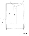
- connection opening 24 is arranged centered in the intermediate wall 22 and also opposite the setting plates 16. Furthermore, in particular Fig. 4 it can be seen that the connection opening 24 and thus also the intermediate valve 26, are made only very narrow. In this case, the width of the connection opening 24, respectively the intermediate valve 26 corresponds to approximately 20% of the height of the connection opening 24, respectively of the intermediate valve 26.
- the width of the connecting opening 24, respectively of the intermediate valve 26, and up to 50% of the height of the connection opening 24, respectively, of the intermediate valve 26 amount.
Landscapes
- Engineering & Computer Science (AREA)
- Health & Medical Sciences (AREA)
- Life Sciences & Earth Sciences (AREA)
- Molecular Biology (AREA)
- Mechanical Engineering (AREA)
- General Engineering & Computer Science (AREA)
- Drying Of Solid Materials (AREA)
Abstract
Description
- Die vorliegende Erfindung betrifft eine horizontale Gefriertrocknungsanlage gemäß dem Oberbegriff des Anspruches 1.
- Die Produktkammer einer Gefriertrocknungsanlage wird während des Gefriertrocknungsprozesses sehr stark evakuiert und abgekühlt. Bei einer vertikalen Gefriertrocknungsanlage wird die Luft aus der Produktkammer in eine unterhalb der Produktkammer angebrachte Kondensatorkammer gesaugt, in der die in der Luft befindliche Feuchtigkeit auskondensieren kann. Die Öffnung zwischen der Produktkammer und der Kondensatorkammer ist dabei so groß ausgebildet, dass eine Person dort hindurchgelangen kann, um innerhalb der Kondensatorkammer Wartungsarbeiten durchzuführen. Aufgrund der Anordnung der Kondensatorkammer und der Anordnung der einzelnen Kondensatorschlangen, ist dies die einzige sinnvolle Zugangsart.
- Aus dem Stand der Technik sind auch horizontale Gefriertrocknungsanlagen bekannt, bei denen die Kondensatorkammer rückwärtig oder seitlich an die Produktkammer angeschlossen ist. Hierbei sind die Strömungsbedingungen innerhalb der Produktkammer für die unteren und oberen Stellplatten gleich. Allerdings sind nun die Strömungsbedingungen für die mittleren Stellplatten ungleich besser, so dass hier eine ungleichmäßige Gefriertrocknung erfolgt.
- Bei einer solchen, beispielsweise rückwärtig angebrachten Kondensatorkammer ist es möglich, auf der Rückseite der Kondensatorkammer eine Revisionsöffnung vorzusehen, so dass die in der Zwischenwand zwischen Produktkammer und Kondensatorkammer befindliche Öffnung und das dazugehörige Zwischenventil nicht mehr als Revisionsöffnung fungieren braucht. Die aus dem Stand der Technik bekannten Zwischenventile sind in der Regel kreisrund ausgeführt und haben einen Durchmesser von bis zu 1,1 m bei einer Höhe der Kondensatorkammer von bis zu 3 m.
- Davon ausgehend liegt der vorliegenden Erfindung die Aufgabe zu Grunde, eine horizontale Gefriertrocknungsanlage der eingangs genannten Art zu schaffen, bei der das zu evakuierende Medium aus allen Bereichen der Produktkammer möglichst gleichmäßig und widerstandsarm herausströmen kann, um das in der Produktkammer befindliche Gefriertrocknungsgut möglichst gleich-mäßig gefrier zu trocknen.
- Als technische Lösung dieser Aufgabe wird erfindungsgemäß eine horizontale Gefriertrocknungsanlage mit den Merkmalen des Anspruches 1 vorgeschlagen. Vorteilhafte Weiterbildungen dieser Vorrichtung sind den Unteransprüchen zu entnehmen.
- Eine nach dieser technischen Lehre ausgebildete horizontale Gefriertrocknungsanlage hat den Vorteil, dass durch die Anpassung der Höhe der Verbindungsöffnung an die Höhe der Stellplatten das Medium im Bereich der oberen Stellplatten genauso wie das Medium im Bereich der unteren Stellplatten, und das Medium im Bereich der mittleren Stellplatten einen kurzen und direkten Weg durch die in der Höhe angepasste Verbindungsöffnung zurücklegt, um in die Kondensatorkammer zu gelangen. Hierdurch sind für alle Stellplatten im Wesentlichen gleiche Strömungsbedingungen geschaffen, so dass eine gleichmäßige Gefriertrocknung des Produktgutes erreicht wird.
- Ein weiterer Vorteil besteht darin, dass das Medium nur wenige Hindernisse zu überwinden braucht und nur wenig umgelenkt wird, so dass es widerstandsarm von den Stellplatten durch die Verbindungsöffnung in die Kondensatorkammer gelangen kann. Diese günstigen Strömungsverhältnisse bewirken eine schnellere Evakuierung der Produktkammer und eine gleichmäßige Gefriertrocknung sämtlichen Gefriertrocknungsgutes, egal ob dieses auf einer oberen, mittleren oder unteren Stellplatte angeordnet ist.
- Noch ein weiterer Vorteil besteht darin, dass die Verbindungsöffnung auch als Revisionsöffnung genutzt werden kann, weil die Verbindungsöffnung so groß ausgebildet ist, dass eine Person hindurchgelangen kann. Dies reduziert die Fertigungskosten, da auf eine separate Revisionsöffnung verzichtet werden kann.
- Dabei hat es sich als vorteilhaft erwiesen, die Verbindungsöffnung gegenüber den Stellplatten zentriert anzuordnen. Hiermit wird erreicht, dass die auch vom Medium zurückzulegenden Wege seitlich von den Stellplatten betrachtet von allen Bereichen der Stellplatten zur Verbindungsöffnung gleich ist, was die Strömungsverhältnisse weiter angleicht.
- Auch wenn die Verbindungsöffnung idealerweise genau so hoch ausgebildet ist, wie die Höhe der Stellplatten zusammen, so werden die hier genannten Vorteile größtenteils auch dann erzielt, wenn die Verbindungsöffnung nur 70 % oder etwas mehr der Höhe der Stellplatten aufweist.
- In einer bevorzugten Ausführungsform ist das Zwischenventil über mindestens zwei, vorzugsweise vier Führungsstangen verschiebbar gehalten. Dabei wird das Zwischenventil über einen Hubkolben parallel zur Zwischenwand in die Kondensatorkammer eingefahren, um die Verbindungsöffnung zu öffnen. Die zwei, respektive vier Führungsstangen, bewirken, dass ein Verkanten des Zwischenventils während des Öffnens oder Schließens verhindert wird und dass das doch sehr große Zwischenventil parallel an der Zwischenwand herangefahren wird und bündig an dieser anliegt, um die Verbindungsöffnung bei Bedarf auch ausreichend dicht zu verschließen. Dabei hat es sich als vorteilhaft erwiesen, das Zwischenventil mittels schmiermittelfreien Gleitlagern an den Führungsstangen zu halten, um die in der pharmazeutischen Industrie erforderlichen Hygienestandards in einfacher Weise einhalten zu können.
- In einer anderen, bevorzugten Ausführungsform ist am Zwischenventil ein Wärmetauscher angebracht, welcher flächen- oder schlangenförmig aufgebaut sein kann, wodurch das Zwischenventil selbst ebenfalls gekühlt werden kann. Hierdurch wird eine gleichmäßigere Temperierung der Produktkammer erreicht.
- Weitere Vorteile der erfindungsgemäßen Gefriertrocknungsanlage ergeben sich aus der beigefügten Zeichnung und den nachstehend beschriebenen Ausführungsformen. Ebenso können die vorstehend genannten und die noch weiter ausgeführten Merkmale erfindungsgemäß jeweils einzeln oder in beliebigen Kombinationen miteinander verwendet werden. Die erwähnten Ausführungsformen sind nicht als abschließende Aufzählung zu verstehen, sondern haben vielmehr beispielhaften Charakter. Es zeigen:
- Fig. 1
- eine geschnitten dargestellte Seitenansicht einer erfindungsgemäßen Gefriertrocknungsanlage mit geschlossenem Zwischenventil;
- Fig. 2
- die Gefriertrocknungsanlage gemäß Fig. 1 mit geöffnetem Zwischenventil;
- Fig. 3
- eine Detailvergrößerung gemäß Linie III in Fig. 2;
- Fig. 4
- eine geschnitten dargestellte Frontansicht der Gefriertrocknungsanlage gemäß Fig. 1, geschnitten entlang Linie IV- IV in Fig. 1;
- Fig. 5
- eine geschnitten dargestellte Frontansicht der Gefriertrocknungsanlage gemäß Fig. 1, geschnitten entlang Linie V- V in Fig. 2.
- In den Figuren 1 bis 5 ist eine erfindungsgemäße Gefriertrocknungsanlage dargestellt, die eine Produktkammer 10 und eine rückwärtig an die Produktkammer 10 angeschlossene Kondensatorkammer 12 umfasst. An einer Vorderseite der Produktkammer 10 ist eine Beschickungsöffnung 14 eingerichtet, während innerhalb der Produktkammer 10 eine Anzahl von übereinander angeordneten Stellplatten vorgesehen ist. Oberhalb der Stellplatten 16 ist eine Druckplatte 18 angeordnet, wobei die Stellplatten 16 über einen hier nur sehr schematisch angedeuteten Verstellmechanismus 20 vertikal verstellbar sind. Auf der der Beschickungsöffnung gegenüberliegenden Seite der Druckkammer 10 ist in einer sowohl der Produktkammer 10, als auch der Kondensatorkammer 12 zuzurechnenden Zwischenwand 22 eine Verbindungsöffnung 24 vorgesehen, welche über ein Zwischenventil 26 verschließbar ist.
- In der Kondensatorkammer 12 ist eine Anzahl von Kondensatorschlangen 28 vorgesehen, an denen der sich im Medium befindliche Wasserdampf aufkondensieren kann. Das Zwischenventil 26 ist über vier Führungsstangen 30 verschiebbar in der Kondensatorkammer 12 gehalten und wird über einen Hubkolben 32 vor- und zurückgefahren. Dabei sind jeweils am oberen und unteren Rand des Zwischenventils 26 je zwei Führungshülsen 34 vorgesehen, in denen je eine Führungsbuchse 36 aus Teflon gehalten ist. Mit dieser Führungsbuchse 36 gleitet das Zwischenventil 26 sehr reibungsarm auf den Führungsstangen 30 aus Edelstahl, so dass auf ein Gleitmittel verzichtet werden kann. Um ein Verkanten des Zwischenventils 26 zuverlässig zu vermeiden, entspricht die Länge der Führungsbuchse 36 etwa dem fünffachen Durchmesser der Führungsstange 30. An den Rändern des Zwischenventils 26 ist eine handelsübliche Dichtung vorgesehen, so dass das Zwischenventil 26 die Verbindungsöffnung 24 zuverlässig abdichtet, auch wenn in der Produktkammer 10, respektive am Zwischenventil 26, ein sehr hoher Differenzdruck anliegt.
- In einer anderen, hier nicht dargestellten Ausführungsform ist die Führungsbuchse 36 aus POM, PEEK oder einem anderen reibungsarmen Material gebildet.
- In noch einer anderen, hier nicht dargestellten Ausführungsform sind an der der Kondensatorkammer 12 zugewandten Seite des Zwischenventils 26 Wärmetauscherflächen oder Kühlschlangen angebracht, um auch das Zwischenventil 26 temperieren zu können. Alternativ können die Wärmetauscherflächen oder die Kühlschlangen auch auf der der Produktkammer zugewandten Seite des Zwischenventils angebracht sein.
- Wie den Figuren 1 und 2 zu entnehmen ist, ist die Verbindungsöffnung 24 und damit korrespondierend das Zwischenventil 26 so dimensioniert, dass sich beide um die gesamte Höhe der Stellplatten 16 im ausgefahrenen Zustand erstrecken. Das heißt, der obere Rand der Verbindungsöffnung 24 befindet sich in etwa auf Höhe der Druckplatte 18, während sich der untere Rand der Verbindungsöffnung 24 in etwa auf Höhe der untersten Stellplatte 16 befindet, wobei die Stellplatten 16 auf ihren maximalen Abstand eingestellt sind.
- In einer anderen, hier nicht dargestellten Ausführungsform entspricht die Höhe der Verbindungsöffnung 24 und die Höhe des Zwischenventils 26 in etwa 70 % der Höhe der Stellplatten 16 in ausgefahrenem Zustand.
- Wie insbesondere Fig. 4 zu entnehmen ist, ist die Verbindungsöffnung 24 in der Zwischenwand 22 und auch gegenüber den Stellplatten 16 zentriert angeordnet. Des Weiteren ist insbesondere Fig. 4 zu entnehmen, dass die Verbindungsöffnung 24 und damit auch das Zwischenventil 26, nur sehr schmal ausgeführt sind. Dabei entspricht die Breite der Verbindungsöffnung 24, respektive das Zwischenventil 26 in etwa 20 % der Höhe der Verbindungsöffnung 24, respektive des Zwischenventils 26.
- In einer anderen, hier nicht dargestellten Ausführungsform kann die Breite der Verbindungsöffnung 24, respektive des Zwischenventils 26, auch bis zu 50 % der Höhe der Verbindungsöffnung 24, respektive des Zwischenventils 26 betragen.
- Durch das Anpassen der Höhe der Verbindungsöffnung 24, respektive des Zwischenventils 26 an die Höhe der Stellplatten 16 wird erreicht, dass das aus der Produktkammer 10 entweichende Medium sehr gleichmäßig und ohne hohe Strömungswiderstände durch die Verbindungsöffnung 24 in die Kondensatorkammer 12 gelangen kann. Dieses gleichmäßige Absaugen des Mediums aus der Produktkammer 10 bewirkt daher ein gleichmäßiges Trocknen des auf den Stellplatten angeordneten Gefriertrocknungsgutes, so dass die zu trocknende Charge eine sehr gleichmäßige Trocknungsqualität aufweist, was letztendlich zu einer höheren Produktqualität und zur Vermeidung von Ausschuss führt.
-
- 10
- Produktkammer
- 12
- Kondensatorkammer
- 14
- Beschickungsöffnung
- 16
- Stellplatten
- 18
- Druckplatte
- 20
- Verstellmechanismus
- 22
- Zwischenwand
- 24
- Verbindungsöffnung
- 26
- Zwischenventil
- 28
- Kondensatorschlagen
- 30
- Führungsstange
- 32
- Hubkolben
- 34
- Führungshülse
- 36
- Führungsbuchse
- 38
- Dichtung
Claims (7)
- Horizontale Gefriertrocknungsanlage mit einer Produktkammer (10), an die seitlich oder rückwärtig (horizontal) eine Kondensatorkammer (12) angeschlossen ist, und mit einer Anzahl von in der Produktkammer (10) vorgesehenen Stellplatten (16) zur Aufnahme von Gefriertrocknungsgut, wobei in einer gemeinsamen, vertikal ausgerichteten Zwischenwand (22) von Produktkammer (10) und Kondensatorkammer (12) eine Verbindungsöffnung (24) ausgebildet ist, welche über ein Zwischenventil (26) verschließbar ist,
dadurch gekennzeichnet,
dass die Höhe der Verbindungsöffnung (22) in mindestens 70 %, vorzugsweise 100 %, der Höhe der Stellplatten (16) entspricht. - Gefriertrocknungsanlage nach Anspruch 1,
dadurch gekennzeichnet,
dass die Verbindungsöffnung (22) gegenüber den Stellplatten (16) zentriert angeordnet ist. - Gefriertrocknungsanlage nach einem der vorangehenden Ansprüche,
dadurch gekennzeichnet,
dass die Breite der Verbindungsöffnung (22) zwischen 5% und 60%, vorzugsweise 20%, der Höhe der Verbindungsöffnung (22) entspricht. - Gefriertrocknungsanlage nach einem der vorangehenden Ansprüche,
dadurch gekennzeichnet,
dass das Zwischenventil (26) über mindestens zwei, vorzugsweise vier, Führungsstangen (30) verschiebbar gehalten ist. - Gefriertrocknungsanlage nach Anspruch 4,
dadurch gekennzeichnet,
dass das Zwischenventil (26) mittels eines schmiermittelfreien Gleitlagers an Führungsstangen (30) gehalten ist. - Gefriertrocknungsanlage nach Anspruch 5,
dadurch gekennzeichnet,
dass das Gleitlager eine Führungsbuchse (36) aus POM, Teflon, Peak oder einem anderen reibungsarmen Material umfasst. - Gefriertrocknungsanlage nach einem der vorangehenden Ansprüche,
dadurch gekennzeichnet,
dass am Zwischenventil ein Wärmetauscher, insbesondere eine Kühlschlange angebracht ist.
Applications Claiming Priority (1)
| Application Number | Priority Date | Filing Date | Title |
|---|---|---|---|
| DE200510024536 DE102005024536A1 (de) | 2005-05-28 | 2005-05-28 | Horizontale Gefriertrocknungsanlage |
Publications (3)
| Publication Number | Publication Date |
|---|---|
| EP1726902A2 true EP1726902A2 (de) | 2006-11-29 |
| EP1726902A3 EP1726902A3 (de) | 2008-12-03 |
| EP1726902B1 EP1726902B1 (de) | 2015-07-08 |
Family
ID=36922227
Family Applications (1)
| Application Number | Title | Priority Date | Filing Date |
|---|---|---|---|
| EP06008740.0A Expired - Lifetime EP1726902B1 (de) | 2005-05-28 | 2006-04-27 | Horizontale Gefriertrocknungsanlage |
Country Status (3)
| Country | Link |
|---|---|
| EP (1) | EP1726902B1 (de) |
| DE (1) | DE102005024536A1 (de) |
| DK (1) | DK1726902T3 (de) |
Cited By (1)
| Publication number | Priority date | Publication date | Assignee | Title |
|---|---|---|---|---|
| CN117298795A (zh) * | 2023-09-26 | 2023-12-29 | 大唐陕西发电有限公司 | 一种气水分离装置及其使用方法 |
Citations (3)
| Publication number | Priority date | Publication date | Assignee | Title |
|---|---|---|---|---|
| GB1042081A (en) | 1963-03-02 | 1966-09-07 | Leybold Hochvakuum Anlagen | Improvements relating to the freeze drying of materials |
| DE19719398A1 (de) | 1997-05-07 | 1998-11-12 | Amsco Finn Aqua Gmbh | Verfahren zur Steuerung eines Gefriertrocknungsprozesses |
| WO2007115965A1 (en) | 2006-04-10 | 2007-10-18 | F. Hoffmann-La Roche Ag | Apparatus for monitoring freeze-drying process |
Family Cites Families (6)
| Publication number | Priority date | Publication date | Assignee | Title |
|---|---|---|---|---|
| US2994132A (en) * | 1956-08-22 | 1961-08-01 | Neumann Karlheinz | Freeze drying apparatus |
| DE1135828B (de) * | 1959-01-10 | 1962-08-30 | Leybold Hochvakuum Anlagen | Gefriertrocknungsverfahren und -vorrichtung |
| US3299525A (en) * | 1964-06-29 | 1967-01-24 | Fmc Corp | Carrier gas sublimation |
| US4624512A (en) * | 1985-06-10 | 1986-11-25 | Hull Corporation | Processing cabinet with sub-door access |
| DE4334902C2 (de) * | 1993-10-13 | 1998-07-02 | Martin Christ Gefriertrocknung | Gefriertrocknungsanlage |
| DE20008915U1 (de) * | 2000-05-19 | 2001-06-28 | Martin Christ Gefriertrocknungsanlagen GmbH, 37520 Osterode | Gefriertrocknungsanlage |
-
2005
- 2005-05-28 DE DE200510024536 patent/DE102005024536A1/de not_active Withdrawn
-
2006
- 2006-04-27 DK DK06008740.0T patent/DK1726902T3/en active
- 2006-04-27 EP EP06008740.0A patent/EP1726902B1/de not_active Expired - Lifetime
Patent Citations (3)
| Publication number | Priority date | Publication date | Assignee | Title |
|---|---|---|---|---|
| GB1042081A (en) | 1963-03-02 | 1966-09-07 | Leybold Hochvakuum Anlagen | Improvements relating to the freeze drying of materials |
| DE19719398A1 (de) | 1997-05-07 | 1998-11-12 | Amsco Finn Aqua Gmbh | Verfahren zur Steuerung eines Gefriertrocknungsprozesses |
| WO2007115965A1 (en) | 2006-04-10 | 2007-10-18 | F. Hoffmann-La Roche Ag | Apparatus for monitoring freeze-drying process |
Cited By (1)
| Publication number | Priority date | Publication date | Assignee | Title |
|---|---|---|---|---|
| CN117298795A (zh) * | 2023-09-26 | 2023-12-29 | 大唐陕西发电有限公司 | 一种气水分离装置及其使用方法 |
Also Published As
| Publication number | Publication date |
|---|---|
| EP1726902A3 (de) | 2008-12-03 |
| DK1726902T3 (en) | 2015-08-10 |
| EP1726902B1 (de) | 2015-07-08 |
| DE102005024536A1 (de) | 2006-11-30 |
Similar Documents
| Publication | Publication Date | Title |
|---|---|---|
| DE3014276A1 (de) | Fuehrung fuer einen an einem tisch o.dgl. angebrachten auszug | |
| DE2547155B2 (de) | Vorschubrost für Verbrennungsofen | |
| EP1433915A2 (de) | Dämpfungsvorrichtung | |
| DE19901109B4 (de) | Stangenloser Zylinder | |
| EP0031919A1 (de) | Ringspalt-Rohrbündel-Wärmetauscher | |
| CH703729A2 (de) | Backofen mit Unterhitze und Heissluft. | |
| EP2251105B1 (de) | Abzug mit vorgelagerter Fensterführung | |
| DE3642867A1 (de) | Spinnanlage | |
| EP3604988B1 (de) | Kühlgerät mit mehreren temperaturzonen | |
| EP1726902B1 (de) | Horizontale Gefriertrocknungsanlage | |
| DE3130064C2 (de) | Backofen | |
| DE102007062386A1 (de) | Teigbearbeitungsanlage | |
| EP2612574B1 (de) | Kühlmöbel | |
| DE69421271T2 (de) | Mit zirkulierenden Verbrennungsgasen beheizter Ofen für Backwaren | |
| DE4324311A1 (de) | Kryopumpe | |
| DE102018122489A1 (de) | Schwadenkondensator für ein Gargerät sowie Gargerät mit einem solchen Schwadenkondensator | |
| DE1945485B2 (de) | Vorrichtung zum Verstellen der Dichtspalte umlaufender Regenerativ-Lufrvorwärmer | |
| DE1946787C3 (de) | Kühltheke mit Umwälzung der Kühlluft | |
| EP4066692A1 (de) | Kühlraum für die präsentation von gekühlten waren | |
| DE202017103160U1 (de) | Umluftwanne | |
| DE3437237C2 (de) | ||
| DE3837335A1 (de) | Vorrichtung zum kuehlen der form oder der formen einer is- oder ris-maschine zur herstellung von hohlglasartikeln | |
| DE3735225C1 (en) | Device for heating rods, in particular of plastic | |
| DE102013213184A1 (de) | Dunstabzugshaube | |
| DE202022107228U1 (de) | Doppelkolbenpumpe mit axial verschiebbarem Steuerkolben |
Legal Events
| Date | Code | Title | Description |
|---|---|---|---|
| PUAI | Public reference made under article 153(3) epc to a published international application that has entered the european phase |
Free format text: ORIGINAL CODE: 0009012 |
|
| AK | Designated contracting states |
Kind code of ref document: A2 Designated state(s): AT BE BG CH CY CZ DE DK EE ES FI FR GB GR HU IE IS IT LI LT LU LV MC NL PL PT RO SE SI SK TR |
|
| AX | Request for extension of the european patent |
Extension state: AL BA HR MK YU |
|
| PUAL | Search report despatched |
Free format text: ORIGINAL CODE: 0009013 |
|
| AK | Designated contracting states |
Kind code of ref document: A3 Designated state(s): AT BE BG CH CY CZ DE DK EE ES FI FR GB GR HU IE IS IT LI LT LU LV MC NL PL PT RO SE SI SK TR |
|
| AX | Request for extension of the european patent |
Extension state: AL BA HR MK YU |
|
| 17P | Request for examination filed |
Effective date: 20081219 |
|
| 17Q | First examination report despatched |
Effective date: 20090211 |
|
| AKX | Designation fees paid |
Designated state(s): AT BE BG CH CY CZ DE DK EE ES FI FR GB GR HU IE IS IT LI LT LU LV MC NL PL PT RO SE SI SK TR |
|
| GRAP | Despatch of communication of intention to grant a patent |
Free format text: ORIGINAL CODE: EPIDOSNIGR1 |
|
| INTG | Intention to grant announced |
Effective date: 20150212 |
|
| GRAS | Grant fee paid |
Free format text: ORIGINAL CODE: EPIDOSNIGR3 |
|
| GRAA | (expected) grant |
Free format text: ORIGINAL CODE: 0009210 |
|
| AK | Designated contracting states |
Kind code of ref document: B1 Designated state(s): AT BE BG CH CY CZ DE DK EE ES FI FR GB GR HU IE IS IT LI LT LU LV MC NL PL PT RO SE SI SK TR |
|
| REG | Reference to a national code |
Ref country code: GB Ref legal event code: FG4D Free format text: NOT ENGLISH |
|
| REG | Reference to a national code |
Ref country code: AT Ref legal event code: REF Ref document number: 735729 Country of ref document: AT Kind code of ref document: T Effective date: 20150715 Ref country code: CH Ref legal event code: EP |
|
| REG | Reference to a national code |
Ref country code: DK Ref legal event code: T3 Effective date: 20150806 |
|
| REG | Reference to a national code |
Ref country code: NL Ref legal event code: T3 Ref country code: IE Ref legal event code: FG4D Free format text: LANGUAGE OF EP DOCUMENT: GERMAN |
|
| REG | Reference to a national code |
Ref country code: DE Ref legal event code: R096 Ref document number: 502006014407 Country of ref document: DE |
|
| REG | Reference to a national code |
Ref country code: LT Ref legal event code: MG4D |
|
| PG25 | Lapsed in a contracting state [announced via postgrant information from national office to epo] |
Ref country code: GR Free format text: LAPSE BECAUSE OF FAILURE TO SUBMIT A TRANSLATION OF THE DESCRIPTION OR TO PAY THE FEE WITHIN THE PRESCRIBED TIME-LIMIT Effective date: 20151009 Ref country code: LV Free format text: LAPSE BECAUSE OF FAILURE TO SUBMIT A TRANSLATION OF THE DESCRIPTION OR TO PAY THE FEE WITHIN THE PRESCRIBED TIME-LIMIT Effective date: 20150708 Ref country code: LT Free format text: LAPSE BECAUSE OF FAILURE TO SUBMIT A TRANSLATION OF THE DESCRIPTION OR TO PAY THE FEE WITHIN THE PRESCRIBED TIME-LIMIT Effective date: 20150708 Ref country code: FI Free format text: LAPSE BECAUSE OF FAILURE TO SUBMIT A TRANSLATION OF THE DESCRIPTION OR TO PAY THE FEE WITHIN THE PRESCRIBED TIME-LIMIT Effective date: 20150708 |
|
| PG25 | Lapsed in a contracting state [announced via postgrant information from national office to epo] |
Ref country code: PT Free format text: LAPSE BECAUSE OF FAILURE TO SUBMIT A TRANSLATION OF THE DESCRIPTION OR TO PAY THE FEE WITHIN THE PRESCRIBED TIME-LIMIT Effective date: 20151109 Ref country code: PL Free format text: LAPSE BECAUSE OF FAILURE TO SUBMIT A TRANSLATION OF THE DESCRIPTION OR TO PAY THE FEE WITHIN THE PRESCRIBED TIME-LIMIT Effective date: 20150708 Ref country code: ES Free format text: LAPSE BECAUSE OF FAILURE TO SUBMIT A TRANSLATION OF THE DESCRIPTION OR TO PAY THE FEE WITHIN THE PRESCRIBED TIME-LIMIT Effective date: 20150708 Ref country code: IS Free format text: LAPSE BECAUSE OF FAILURE TO SUBMIT A TRANSLATION OF THE DESCRIPTION OR TO PAY THE FEE WITHIN THE PRESCRIBED TIME-LIMIT Effective date: 20151108 Ref country code: SE Free format text: LAPSE BECAUSE OF FAILURE TO SUBMIT A TRANSLATION OF THE DESCRIPTION OR TO PAY THE FEE WITHIN THE PRESCRIBED TIME-LIMIT Effective date: 20150708 |
|
| REG | Reference to a national code |
Ref country code: DE Ref legal event code: R097 Ref document number: 502006014407 Country of ref document: DE |
|
| REG | Reference to a national code |
Ref country code: FR Ref legal event code: PLFP Year of fee payment: 11 |
|
| PG25 | Lapsed in a contracting state [announced via postgrant information from national office to epo] |
Ref country code: CZ Free format text: LAPSE BECAUSE OF FAILURE TO SUBMIT A TRANSLATION OF THE DESCRIPTION OR TO PAY THE FEE WITHIN THE PRESCRIBED TIME-LIMIT Effective date: 20150708 Ref country code: SK Free format text: LAPSE BECAUSE OF FAILURE TO SUBMIT A TRANSLATION OF THE DESCRIPTION OR TO PAY THE FEE WITHIN THE PRESCRIBED TIME-LIMIT Effective date: 20150708 Ref country code: EE Free format text: LAPSE BECAUSE OF FAILURE TO SUBMIT A TRANSLATION OF THE DESCRIPTION OR TO PAY THE FEE WITHIN THE PRESCRIBED TIME-LIMIT Effective date: 20150708 |
|
| PLBE | No opposition filed within time limit |
Free format text: ORIGINAL CODE: 0009261 |
|
| STAA | Information on the status of an ep patent application or granted ep patent |
Free format text: STATUS: NO OPPOSITION FILED WITHIN TIME LIMIT |
|
| PG25 | Lapsed in a contracting state [announced via postgrant information from national office to epo] |
Ref country code: RO Free format text: LAPSE BECAUSE OF FAILURE TO SUBMIT A TRANSLATION OF THE DESCRIPTION OR TO PAY THE FEE WITHIN THE PRESCRIBED TIME-LIMIT Effective date: 20150708 |
|
| 26N | No opposition filed |
Effective date: 20160411 |
|
| PG25 | Lapsed in a contracting state [announced via postgrant information from national office to epo] |
Ref country code: SI Free format text: LAPSE BECAUSE OF FAILURE TO SUBMIT A TRANSLATION OF THE DESCRIPTION OR TO PAY THE FEE WITHIN THE PRESCRIBED TIME-LIMIT Effective date: 20150708 |
|
| GBPC | Gb: european patent ceased through non-payment of renewal fee |
Effective date: 20160427 |
|
| PG25 | Lapsed in a contracting state [announced via postgrant information from national office to epo] |
Ref country code: LU Free format text: LAPSE BECAUSE OF FAILURE TO SUBMIT A TRANSLATION OF THE DESCRIPTION OR TO PAY THE FEE WITHIN THE PRESCRIBED TIME-LIMIT Effective date: 20160427 |
|
| REG | Reference to a national code |
Ref country code: IE Ref legal event code: MM4A |
|
| PG25 | Lapsed in a contracting state [announced via postgrant information from national office to epo] |
Ref country code: GB Free format text: LAPSE BECAUSE OF NON-PAYMENT OF DUE FEES Effective date: 20160427 |
|
| REG | Reference to a national code |
Ref country code: FR Ref legal event code: PLFP Year of fee payment: 12 |
|
| PG25 | Lapsed in a contracting state [announced via postgrant information from national office to epo] |
Ref country code: IE Free format text: LAPSE BECAUSE OF NON-PAYMENT OF DUE FEES Effective date: 20160427 |
|
| REG | Reference to a national code |
Ref country code: FR Ref legal event code: PLFP Year of fee payment: 13 |
|
| PG25 | Lapsed in a contracting state [announced via postgrant information from national office to epo] |
Ref country code: CY Free format text: LAPSE BECAUSE OF FAILURE TO SUBMIT A TRANSLATION OF THE DESCRIPTION OR TO PAY THE FEE WITHIN THE PRESCRIBED TIME-LIMIT Effective date: 20150708 Ref country code: HU Free format text: LAPSE BECAUSE OF FAILURE TO SUBMIT A TRANSLATION OF THE DESCRIPTION OR TO PAY THE FEE WITHIN THE PRESCRIBED TIME-LIMIT; INVALID AB INITIO Effective date: 20060427 |
|
| PG25 | Lapsed in a contracting state [announced via postgrant information from national office to epo] |
Ref country code: MC Free format text: LAPSE BECAUSE OF FAILURE TO SUBMIT A TRANSLATION OF THE DESCRIPTION OR TO PAY THE FEE WITHIN THE PRESCRIBED TIME-LIMIT Effective date: 20150708 Ref country code: TR Free format text: LAPSE BECAUSE OF FAILURE TO SUBMIT A TRANSLATION OF THE DESCRIPTION OR TO PAY THE FEE WITHIN THE PRESCRIBED TIME-LIMIT Effective date: 20150708 |
|
| PG25 | Lapsed in a contracting state [announced via postgrant information from national office to epo] |
Ref country code: BG Free format text: LAPSE BECAUSE OF FAILURE TO SUBMIT A TRANSLATION OF THE DESCRIPTION OR TO PAY THE FEE WITHIN THE PRESCRIBED TIME-LIMIT Effective date: 20150708 |
|
| PGFP | Annual fee paid to national office [announced via postgrant information from national office to epo] |
Ref country code: NL Payment date: 20250418 Year of fee payment: 20 |
|
| PGFP | Annual fee paid to national office [announced via postgrant information from national office to epo] |
Ref country code: DE Payment date: 20250228 Year of fee payment: 20 |
|
| PGFP | Annual fee paid to national office [announced via postgrant information from national office to epo] |
Ref country code: DK Payment date: 20250429 Year of fee payment: 20 |
|
| PGFP | Annual fee paid to national office [announced via postgrant information from national office to epo] |
Ref country code: BE Payment date: 20250418 Year of fee payment: 20 Ref country code: IT Payment date: 20250424 Year of fee payment: 20 |
|
| PGFP | Annual fee paid to national office [announced via postgrant information from national office to epo] |
Ref country code: FR Payment date: 20250423 Year of fee payment: 20 |
|
| PGFP | Annual fee paid to national office [announced via postgrant information from national office to epo] |
Ref country code: CH Payment date: 20250501 Year of fee payment: 20 |
|
| PGFP | Annual fee paid to national office [announced via postgrant information from national office to epo] |
Ref country code: AT Payment date: 20250423 Year of fee payment: 20 |
|
| REG | Reference to a national code |
Ref country code: CH Ref legal event code: H14 Free format text: ST27 STATUS EVENT CODE: U-0-0-H10-H14 (AS PROVIDED BY THE NATIONAL OFFICE) Effective date: 20260427 Ref country code: DE Ref legal event code: R071 Ref document number: 502006014407 Country of ref document: DE |
|
| REG | Reference to a national code |
Ref country code: NL Ref legal event code: MK Effective date: 20260426 |
|
| REG | Reference to a national code |
Ref country code: DK Ref legal event code: EUP Expiry date: 20260427 |
|
| REG | Reference to a national code |
Ref country code: BE Ref legal event code: MK Effective date: 20260427 |
|
| REG | Reference to a national code |
Ref country code: AT Ref legal event code: MK07 Ref document number: 735729 Country of ref document: AT Kind code of ref document: T Effective date: 20260427 |