EP1726410A2 - Outil motorisé - Google Patents
Outil motorisé Download PDFInfo
- Publication number
- EP1726410A2 EP1726410A2 EP06010929A EP06010929A EP1726410A2 EP 1726410 A2 EP1726410 A2 EP 1726410A2 EP 06010929 A EP06010929 A EP 06010929A EP 06010929 A EP06010929 A EP 06010929A EP 1726410 A2 EP1726410 A2 EP 1726410A2
- Authority
- EP
- European Patent Office
- Prior art keywords
- power tool
- battery pack
- main body
- portions
- engaging
- Prior art date
- Legal status (The legal status is an assumption and is not a legal conclusion. Google has not performed a legal analysis and makes no representation as to the accuracy of the status listed.)
- Granted
Links
- 238000003780 insertion Methods 0.000 claims abstract description 19
- 230000037431 insertion Effects 0.000 claims abstract description 19
- 238000007599 discharging Methods 0.000 description 7
- 238000000465 moulding Methods 0.000 description 7
- 230000008878 coupling Effects 0.000 description 5
- 238000010168 coupling process Methods 0.000 description 5
- 238000005859 coupling reaction Methods 0.000 description 5
- 238000000926 separation method Methods 0.000 description 5
- 239000002184 metal Substances 0.000 description 3
- 238000004891 communication Methods 0.000 description 2
- 238000010586 diagram Methods 0.000 description 2
- 230000006835 compression Effects 0.000 description 1
- 238000007906 compression Methods 0.000 description 1
- 238000013461 design Methods 0.000 description 1
- 238000001514 detection method Methods 0.000 description 1
- 239000011796 hollow space material Substances 0.000 description 1
- 238000009434 installation Methods 0.000 description 1
- 239000011810 insulating material Substances 0.000 description 1
- 238000000034 method Methods 0.000 description 1
- 238000012986 modification Methods 0.000 description 1
- 230000004048 modification Effects 0.000 description 1
Images


Classifications
-
- B—PERFORMING OPERATIONS; TRANSPORTING
- B25—HAND TOOLS; PORTABLE POWER-DRIVEN TOOLS; MANIPULATORS
- B25F—COMBINATION OR MULTI-PURPOSE TOOLS NOT OTHERWISE PROVIDED FOR; DETAILS OR COMPONENTS OF PORTABLE POWER-DRIVEN TOOLS NOT PARTICULARLY RELATED TO THE OPERATIONS PERFORMED AND NOT OTHERWISE PROVIDED FOR
- B25F5/00—Details or components of portable power-driven tools not particularly related to the operations performed and not otherwise provided for
- B25F5/02—Construction of casings, bodies or handles
Definitions
- the present invention relates to a power tool; and, more particularly, to a technique for detachably attaching a battery pack to a power tool main body.
- a conventional power tool there is known one including a power tool main body and a battery pack for accommodating therein a storage battery.
- the battery pack has a case provided with a positive and a negative charging/discharging terminals and a right and a left slide rails.
- the power tool main body has a housing provided with a positive and a negative power supply terminals and a pair of guide rails capable of slidably supporting the right and the left slide rails (see, e.g., Japanese Patent Laid-open Application No. 2001-143678 ).
- the battery pack is attached to the power tool, as disclosed in Japanese Patent Laid-open Application No. 2001- 143678 , by first sliding the slide rails of the battery pack slide into the guide rails of the power tool main body to thereby electrically connect the positive and the negative charging/discharging terminals and the positive and the negative power supply terminals, followed by respective coupling of the slide rails of the battery pack with their corresponding guide rails of the power tool main body.
- an object of the present invention to provide a power tool capable of: easily attaching a battery pack to a power tool main body with one-touch operation; enabling an attachment/detachment in a limited space by reducing a distance required to move for the attachment/detachment, compared to the conventional case requiring a slide insertion operation between slide rails and guide rails; preventing other members from being damaged when an excessive separation force is applied during the detachment of the battery pack from the power tool main body; and avoiding an improper attachment of the battery pack, a battery pack having a different voltage and a possibility of terminals or connector signal lines being short-circuited when the battery pack is not in use.
- a power tool including: a power tool main body having a motor, a reduction unit and an output unit; and a battery pack for accommodating therein a battery, the battery pack being detachably attached to the power tool main body, wherein the battery pack is provided with an attaching portion having a positive and negative terminal for connecting a power supply to the power tool main body and at least two engaging portions to be mechanically coupled to the power tool main body, wherein the power tool main body is provided with an attached portion having engaged portions respectively corresponding to said at least two engaging portions of the battery pack respectively, wherein each of engaging portions of the battery pack includes an insertion restricting portion and an attachment securing portion for allowing its corresponding engaged portion to be inserted only in a direction of pressing the attaching portion of the battery pack against the attached portion of the power tool main body, each of the attachment securing portions being coupled to its corresponding engaged portion, and wherein at least one of said at least two engaging portions further has a hook engaging portion which is selectively secured with an engaged portion moved
- Fig. 1 shows a perspective view of a battery pack 2 in accordance with a first preferred embodiment of the present invention
- Fig. 2 describes a perspective view of the battery pack 2 after an outer case thereof has been removed
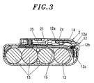
- Fig. 3 provides a cross sectional view of the battery pack 2 shown in Fig. 1.
- a power tool in accordance with a first preferred embodiment of the present includes a power tool main body 1 (see Fig. 5A) such as an impact driver or the like and a battery pack 2 detachably attached to the power tool main body 1.
- a power tool main body 1 such as an impact driver or the like
- a battery pack 2 detachably attached to the power tool main body 1.
- the battery pack 2 is a box body accommodating therein a plurality of storage batteries (hereinafter, referred to as "cells 13") connected by interconnection plates.
- the box body has a double structure in which an outer case 14 accommodates therein a comparatively smaller inner case 15 for covering the cells 13.
- the outer case 14 is configured by assembling an upper case and a lower case, wherein the upper case has an attaching portion 2a to be commonly attached to a battery charger and the power tool main body 1.
- the outer case 14 is of an approximately rectangular shape when seen from the top.
- three engaging portions 4, 4' and 4" are respectively provided at two longitudinal sides of the attaching portion 2a.
- the engaging portions 4, 4' and 4" are vertically raised with respect to a main surface 2b of the attaching portion 2a. As shown in Fig.
- the engaging portions 4, 4', 4" include insertion restricting portions 4a, 4a', 4a” and L-shaped attachment securing portions 4b, 4b', 4b" for allowing their corresponding engaged portions 5, 5', 5" to be inserted only in a direction of pressing the attaching portion 2a of the battery pack 2 against the attached portion 1a of the power tool main body 1, as described later.
- the attachment securing portions 4b, 4b', 4b" are engaged with their corresponding engaged portions 5, 5', 5".
- the engaging portion 4" further has, e.g., two hook engaging portions 12a which are secured with the engaged portions 5" moved from the insertion restricting portions 4a" to the attachment securing portions 4b". Moreover, as shown in Fig.
- a first vertical hole 6 and a first horizontal hole 7 extending therefrom are formed at an inner portion of the engaging portion 4; a second vertical hole 8 and a second horizontal hole 9 extending therefrom are formed at an inner portion of the engaging portion 4'; and a third vertical hole 10 and a third horizontal hole 11 extending therefrom are formed at an inner portion of the engaging portion 4".
- engaging portions are provided on the other longitudinal side of the attachment portion 2a. Accordingly, the engaging portions 4, 4', 4" will be described about one longitudinal side of the attachment portion 2a.
- a hook 12 is accommodated in a hollow space between the outer case 14 and the inner case 15 such that a part of the hook 12 can be protruded to outside of the outer case 14.
- Installed at a base end portion of a body of the hook 12 are two pivots 12c rotatably supported at coupling portions 81 (see Fig. 6A) between the upper case and the lower case of the outer case 14.
- a manipulated part 12b exposed to outside of the outer case 14 is provided at a central portion of the hook 12.
- a leading end portion of the hook 12 opposite to the base end portion thereof has a forked part whose leading two ends are respectively provided with hook engaging portions 12a.
- One of the hook engaging portions 12a is installed at the inner portion of the engaging portion 4" provided at one longitudinal side of the attaching portion 2a, whereas the other hook engaging portion 12a is installed at the inner portion of the engaging portion 4" provided at the other longitudinal side thereof.
- the manipulated part 12b of the hook 12 is supported at the inner case 15 and a hook spring 12d formed of a compression coil spring is interposed therebetween.
- the hook engaging portions 12a are spring-pressed by the hook spring 12d in a direction toward an inner surface of the outer case 14 (in an upward direction of Fig. 5A). Accordingly, parts of the hook engaging portions 12a are elastically contacted with horizontal inner surfaces of the attachment securing portions 4b" of the engaging portions 4".
- the hook 12 pivots in a direction away from the inner surface of the outer case 14 (in a downward direction of Fig.
- top surfaces of the hook engaging portions 12a move slightly lower than horizontal level of horizontal inner surfaces of the attachment securing portions 4b" (the state of Fig. 6A), allowing the protruding engaged portions 5" and the engaging portions 4" to be engaged with each other.
- the hook engaging portion 12a is not provided at the inner portions of the engaging portions 4 and 4', the engaging portions 4 and 4' can be freely engaged with or separated from the L-shaped engaged portions 5 and 5' of the power tool main body 1 without being restricted by the hook 12.
- the attaching portion 2a of the outer case 14 is provided with three recesses 26 to 28 into which charging/discharging male terminals for an electrical connection are inserted respectively.
- the three recesses 26 to 28 are provided inside the three recesses 26 to 28 .
- the three female terminals form a positive and a negative charging/discharging terminal 3a and 3b and a temperature terminal 3c connected to a thermo switch 80.
- the three female terminals (a positive and a negative power supply terminal and a temperature signal detection terminal) are configured in such a way that the terminals 3a, 3b and 3c can be respectively inserted thereinto through the three recesses 26 to 28.
- FIG. 4 shows an exemplary circuit diagram of the printed circuit board 25 attached to the inner case 15.
- reference numerals 20 and 21 representing a temperature detecting thermister and a connector, respectively.
- a positive terminal of one of the cells 13 is connected to the positive charging/discharging terminal 3a and the printed circuit board 25, whereas a negative terminal of the other cell 13 is connected to the negative charging/discharging terminal 3b and the printed circuit board 25 via a switch SW to be described later.
- the connector 21 outputs a voltage signal from the printed circuit board 25, a temperature signal from the thermister 20 or the like, or form a communication circuit between itself as a communication terminal and a battery charger.
- the power tool main body 1 includes a motor 1b, a reduction unit 1c and an output unit 1d, as illustrated in Fig. 5A.
- a bottom surface of a handle portion 1e of the power tool main body 1 serves as an attached portion 1a to which the battery pack 2 is attached.
- Installed at the attached portion 1a is a main body control circuit 90 having thereon a signal connector 91.
- engaged portions 5, 5' and 5" are respectively provided at both sides of the attached portion 1a to correspond to the engaging portions 4, 4' and 4" provided at both sides of the attaching portion 2a of the battery pack 2.
- L-shaped engaged portions 5 and 5" correspond to the engaging portions 4 and 4' of the battery pack 2 respectively and a protruding engaged portion 5" corresponds to the engaging portion 4".
- Each of the L-shaped engaged portions 5 and 5' has a vertical rib 30 and a horizontal rib 31 to be engageable with the engaging portions 4 and 4" of the battery pack 2.
- a horizontal width C of the first vertical hole 6 of the battery pack 2 is equal to a horizontal width C of the second vertical hole 8, as illustrated in Fig. 5A.
- horizontal widths C' of the L-shaped engaged portion 5 and 5' are set.
- the horizontal width C' is set to be slightly smaller than the horizontal width C.
- a horizontal width C1 of the third vertical hole 10 of the battery pack 2 is set to be smaller than the aforementioned horizontal width C, and according thereto, a horizontal distance of the protruding engaged portion 5" of the power tool main body 1 is set.
- the L-shaped engaged portions 5 and 5' of the power tool main body 1 can not be inserted into the third vertical hole 10 of the battery pack 2, thereby preventing misengagement between the engaged portions 5, 5', 5" of the power tool main body 1 and the engaging portions 4, 4', 4" of the battery pack 2. That is, since the horizontal distances C' of the L-shaped engaged portions 5 and 5' are greater than the horizontal width C1 of the third vertical hole 10 of the batter pack 2, the L-shaped engaged portions 5 and 5' can not be inserted into the third vertical hole 10 of the battery pack 2.
- the hook engaging portion 12a is elastically in contact with the horizontal inner surface of the engaging portion 4" and, also, a part thereof is exposed through the third vertical holes 10.
- the attaching portion 2a of the battery pack 2 gets attached to the attached portion 1a of the power tool main body 1 in a direction D of pressing each other, the engaged portions 5, 5' and 5" of the power tool main body 1 become inserted into the engaging portions 4, 4' and 4" of the battery pack 2 through the first to the third vertical holes 6, 8, 10, respectively, as depicted in Fig. 6A.
- the manipulated part 12b of the hook 12 needs to be pushed by, e.g., a finger from the outside.
- the hook 12 rotates downward in an arc shape centering on the pivots 12c, which, in turn, forces the top surface of the hook engaging portion 12a to move slightly lower than a horizontal level of the bottom surface of the protruding engaged portion 5" (the state of Fig. 6A).
- the battery pack 2 can be separated from the power tool main body 1.
- the batter pack 2 can be attached only by pressing the attaching portion 2a of the battery pack 2 against the attached portion 1a of the power tool main body 1 and then horizontally shifting either the power tool main body 1 or the battery pack 2. Therefore, in comparison with the conventional case requiring the slide insertion operation between the slide rails and the guide rails, a distance the members involved are required to move for the attachment is small and, thus, the battery pack 2 can be easily attached/detached in a limited space. Further, it is possible to prevent other members from being damaged when an excessive separation force is exerted during the separation of the battery pack from the power tool main body 1.
- the battery pack 2 can be firmly coupled.
- the engagement between the hook engaging portions 12a and the engaged portions 5" is released by the rotation of the hook 2, thereby enabling to simply separate the battery pack 2 from the power tool main body 1.
- a firm coupling state of the protruding engaged portion 5" can be maintained by the bias force of the hook engaging portions 12a, allowing the battery pack 2 to be firmly engaged to the power tool main body 1.
- the hook engaging portions 12a return to the original positions due to the bias force of the hook spring 12d in a state where the engaged portions 5" are held by the attachment securing portions 4b"
- a click sound is generated by the contact between the horizontal inner surface of the attachment securing portions 4b" and the hook engaging portions 12a, allowing a user to check whether or not the battery pack 2 has been firmly attached.
- horizontal distances F of the L-shaped engaged portions 5 and 5' of the power tool main body 1 are set differently from a horizontal distance F1 of the protruding engaged portions 5" (i.e., F1>F).
- the horizontal width C of the first and the second vertical hole 6 and 8 of the battery pack 2 are set to be different from the horizontal width C1 of the third vertical hole 10 (i.e., C1>C).
- the protruding engaged portions 5" can be inserted only into the third vertical holes 10, thereby preventing an improper insertion.
- the protruding engaged portions 5" can be inserted only into the third vertical holes 10.
- Figs. 8A, 8B and 9 illustrate a third and a fourth preferred embodiments capable of preventing the improper insertion.
- a horizontal distance S2 of the L-shaped engaged portions 5 of the power tool main body 1 is set differently from horizontal distances S of the engaged portions 5' and 5" (i.e., S ⁇ S2). Therefore, as shown in Fig. 8A, a horizontal width S1 of the first vertical holes 6 of the battery pack 2 is set differently from the horizontal widths S of the second and the third vertical hole 8 and 10 (i.e., S ⁇ S1).
- S ⁇ S1 horizontal width of the first vertical holes 6 of the battery pack 2
- a height H1 of a horizontal rib 31a of the L-shaped engaged portions 5 of the power tool main body 1 is set to be greater than heights H of a horizontal rib 31b of the engaged portions 5' and 5". Accordingly, the height H1 of the attachment securing portions 4b of the engaging portions 4 of the battery pack 2 is set to be greater than the vertical position h of the attachment securing portions 4b' and 4b" of the other engaging portion 4' and 4". In this manner, if the horizontal distance of the engaged portion and the horizontal width of the vertical holes, the horizontal distance of the horizontal rib and the protruding engaged portion, or the vertical position of the attachment securing portions are set differently, the improper insertion can be prevented.
- the batter pack 2 is preferably provided with a switch SW for switching a connection of a power supply line of the battery pack 2 during the inserting of the engaged portion 5 into the insertion restricting portion 4a of the engaging portion 4.
- a thrust spring shaped contactor 40 is extended from the negative charging/discharging terminal 3b mounted on the printed circuit board 25 and a leading end of the contactor 40 is covered with molding products 42 made of an insulating material.
- the molding product 42 is provided at an inner portion of the engaging portion 4 or 4' (except the engaging portions 4" where the hook engaging portion 12a is provided). Further, when seen from the top, a part of the molding product 42 is exposed through the vertical hole C of the engaging portion 4 or 4', whereas the other part thereof is covered by the attachment securing portion 4b or 4b'.
- the contactor 40 does not get electrically connected with the sheet metal 41 connected to the cell 13.
- the molding products 42 are pressed by the engaged portions 5 or 5' in a direction indicated by arrow "W" of Fig. 11. Accordingly, the molding products 42 move downward until top surfaces thereof become approximately horizontal with respect to a lower horizontal level of the engaging portion 4 or 4'. In such state, the contactor 40 becomes electrically connected to the sheet metal 41.
- the engaged portions 5 or 5' are inserted into the horizontal holes 7 or 8 to be engaged with the attachment securing portions 4b or 4b'.
- the molding products 42 are pressed by the engaged portions 5 or 5', so that the top surfaces of the molding products 42 become approximately horizontal with respect to the bottom surfaces of the insertion restricting portions 4a or 4a'.
- the installation structure of the battery pack 2 in accordance with the present invention can be widely applied to a battery pack having no connector.
- the present invention can provide a convenient power tool capable of: easily attaching a battery pack to a power tool main body with one-touch operation; enabling an attachment/detachment in a limited space by reducing a distance the members involved are required to move for the attachment/detachment, compared to the conventional case requiring a slide insertion operation between slide rails and guide rails; and preventing other members from being damaged when an excessive separation force is applied during the detachment of the battery pack from the power tool main body.
Landscapes
- Engineering & Computer Science (AREA)
- Mechanical Engineering (AREA)
- Battery Mounting, Suspending (AREA)
- Portable Power Tools In General (AREA)
Applications Claiming Priority (1)
| Application Number | Priority Date | Filing Date | Title |
|---|---|---|---|
| JP2005154686A JP4462112B2 (ja) | 2005-05-26 | 2005-05-26 | 電動工具 |
Publications (3)
| Publication Number | Publication Date |
|---|---|
| EP1726410A2 true EP1726410A2 (fr) | 2006-11-29 |
| EP1726410A3 EP1726410A3 (fr) | 2010-05-05 |
| EP1726410B1 EP1726410B1 (fr) | 2014-07-02 |
Family
ID=36685601
Family Applications (1)
| Application Number | Title | Priority Date | Filing Date |
|---|---|---|---|
| EP06010929.5A Active EP1726410B1 (fr) | 2005-05-26 | 2006-05-26 | Outil motorisé |
Country Status (4)
| Country | Link |
|---|---|
| US (1) | US7567058B2 (fr) |
| EP (1) | EP1726410B1 (fr) |
| JP (1) | JP4462112B2 (fr) |
| CN (2) | CN200951554Y (fr) |
Cited By (6)
| Publication number | Priority date | Publication date | Assignee | Title |
|---|---|---|---|---|
| EP1787763A2 (fr) | 2005-11-17 | 2007-05-23 | Matsushita Electric Works, Ltd. | Outil électrique |
| EP1978578A2 (fr) * | 2007-03-30 | 2008-10-08 | Sony Corporation | Bloc-batteries |
| WO2009076282A1 (fr) * | 2007-12-10 | 2009-06-18 | Illinois Tool Works Inc. | Outil électrique à batterie à complémentarité de forme |
| EP2106885A1 (fr) * | 2008-03-31 | 2009-10-07 | Panasonic Electric Works Co., Ltd. | Outil d'alimentation électrique |
| US9040195B2 (en) | 2007-03-30 | 2015-05-26 | Sony Corporation | Battery pack |
| EP2554335A4 (fr) * | 2010-03-26 | 2018-04-18 | Panasonic Intellectual Property Management Co., Ltd. | Outil électrique |
Families Citing this family (26)
| Publication number | Priority date | Publication date | Assignee | Title |
|---|---|---|---|---|
| DE102005007923B4 (de) * | 2005-02-11 | 2006-10-19 | Alfred Kärcher Gmbh & Co. Kg | Reinigungsgerät |
| US8026698B2 (en) * | 2006-02-09 | 2011-09-27 | Scheucher Karl F | Scalable intelligent power supply system and method |
| US8860377B2 (en) | 2006-02-09 | 2014-10-14 | Karl F. Scheucher | Scalable intelligent power supply system and method |
| USD632649S1 (en) | 2006-09-29 | 2011-02-15 | Karl F. Scheucher | Cordless power supply |
| US7799448B2 (en) * | 2007-06-19 | 2010-09-21 | Black & Decker Inc. | Battery pack for cordless devices |
| KR100940510B1 (ko) * | 2008-09-30 | 2010-02-10 | 주식회사 아이엔피 | 분리형 플러그를 가지는 헤어드라이기의 아크방지장치 |
| JP5288563B2 (ja) * | 2010-03-26 | 2013-09-11 | パナソニック株式会社 | 電動工具 |
| US8343643B2 (en) | 2010-08-20 | 2013-01-01 | Techtronic Power Tools Technology Limited | Battery pack including a support frame |
| JP2012049074A (ja) * | 2010-08-30 | 2012-03-08 | Makita Corp | 電動工具のバッテリパック |
| EP2637233B1 (fr) | 2010-11-04 | 2017-09-06 | Makita Corporation | Assemblage de batteries |
| JP5698546B2 (ja) * | 2011-01-20 | 2015-04-08 | 株式会社マキタ | 充電式電動工具 |
| WO2013139372A1 (fr) | 2012-03-19 | 2013-09-26 | Husqvarna Ab | Adaptateur de courant pour outils électriques sans fil |
| CN108878726B (zh) | 2012-03-19 | 2022-04-22 | 胡斯华纳有限公司 | 用于背包能源的载体系统、能源以及背包能源组件 |
| CN205177900U (zh) | 2012-06-12 | 2016-04-20 | 米沃奇电动工具公司 | 电池组 |
| AU2012393391C1 (en) * | 2012-11-01 | 2016-11-17 | The Gillette Company Llc | Battery operated razor |
| US10027078B2 (en) * | 2014-01-02 | 2018-07-17 | Sears Brands, L.L.C. | Slide battery and power tool for use with both slide and post batteries |
| US9893384B2 (en) | 2014-05-18 | 2018-02-13 | Black & Decker Inc. | Transport system for convertible battery pack |
| EP3273569B1 (fr) | 2014-05-18 | 2018-08-15 | Black & Decker, Inc. | Système d'outillage électrique |
| AU362572S (en) | 2014-11-26 | 2015-07-15 | Techtronic Ind Co Ltd | Battery |
| US10553843B2 (en) | 2016-03-28 | 2020-02-04 | Transform Sr Brands Llc | Portable power tool, battery pack, and cell configurations for same |
| DE102016120329A1 (de) * | 2016-10-25 | 2018-04-26 | Festool Gmbh | Anschlussvorrichtung eines Elektrogeräts oder eines Energiespeichers |
| EP3336926B1 (fr) * | 2016-12-16 | 2019-03-06 | Defond Electech Co., Ltd | Procédé et système d'utilisation pour relier de manière opérationnelle un bloc-batterie à une machine |
| WO2018119256A1 (fr) | 2016-12-23 | 2018-06-28 | Black & Decker Inc. | Système d'outil électrique sans fil |
| WO2018193730A1 (fr) * | 2017-04-18 | 2018-10-25 | ソニー株式会社 | Dispositif d'alimentation en énergie et procédé d'alimentation en énergie |
| US10707459B2 (en) * | 2017-07-20 | 2020-07-07 | Robert Bosch Tool Corporation | Transportation safe battery |
| WO2019031272A1 (fr) * | 2017-08-09 | 2019-02-14 | 工機ホールディングス株式会社 | Système de dispositif électrique, dispositif électrique et dispositif d'alimentation électrique |
Family Cites Families (22)
| Publication number | Priority date | Publication date | Assignee | Title |
|---|---|---|---|---|
| US5336953A (en) * | 1991-12-21 | 1994-08-09 | Scintilla Ag | Battery-powered electrical hand-tool |
| US6018227A (en) * | 1998-06-22 | 2000-01-25 | Stryker Corporation | Battery charger especially useful with sterilizable, rechargeable battery packs |
| US6168881B1 (en) * | 1998-08-14 | 2001-01-02 | S-B Power Tool Company | Latch mechanism for a battery operated power tool |
| DE19905085A1 (de) * | 1999-01-29 | 2000-08-03 | Black & Decker Inc N D Ges D S | Batteriegetriebenes, handgeführtes Elektrowerkzeug |
| JP4110656B2 (ja) * | 1999-02-17 | 2008-07-02 | ソニー株式会社 | バッテリーパック、バッテリー装着装置、電力供給装置及び電子機器 |
| US6656626B1 (en) * | 1999-06-01 | 2003-12-02 | Porter-Cable Corporation | Cordless power tool battery release mechanism |
| US6181032B1 (en) * | 1999-07-14 | 2001-01-30 | Black & Decker Inc. | Releasably connecting power packs to electrical appliances |
| JP3698296B2 (ja) * | 1999-08-19 | 2005-09-21 | 株式会社マキタ | 端子構造 |
| JP2001155700A (ja) * | 1999-11-24 | 2001-06-08 | Makita Corp | バッテリーパック |
| JP2001300867A (ja) * | 2000-04-21 | 2001-10-30 | Makita Corp | 電動工具用アダプタ |
| US6525511B2 (en) * | 2000-08-11 | 2003-02-25 | Milwaukee Electric Tool Corporation | Adapter for a power tool battery |
| JP3805664B2 (ja) * | 2001-11-01 | 2006-08-02 | 株式会社マキタ | 電池パック |
| US20030102844A1 (en) * | 2001-11-24 | 2003-06-05 | Rudolph Bailey | Automatic selfcharging power tools |
| DE10212750B4 (de) * | 2002-03-22 | 2006-04-20 | Robert Bosch Gmbh | Akkupack-System für Handwerkzeugmaschinen |
| DE10362314B3 (de) * | 2002-11-22 | 2023-05-11 | Milwaukee Electric Tool Corp. | Lithium-Ionen-Batteriesatz |
| US7253585B2 (en) * | 2002-11-22 | 2007-08-07 | Milwaukee Electric Tool Corporation | Battery pack |
| DE10304656A1 (de) * | 2003-02-05 | 2004-08-19 | Mobiletron Electronics Co., Ltd. | Ladegerät für Elektrowerkzeug |
| US6955549B2 (en) * | 2003-05-28 | 2005-10-18 | One World Technologies Limited | Slide type battery ejection mechanism |
| DE10348693B4 (de) * | 2003-10-16 | 2009-06-04 | Hilti Aktiengesellschaft | Elektrische Verbindungsvorrichtung für Handwerkzeugzusatzgeräte |
| KR20050090784A (ko) * | 2004-03-10 | 2005-09-14 | 삼성전자주식회사 | 배터리 록킹장치 |
| US7176656B2 (en) * | 2004-06-22 | 2007-02-13 | Campbell Hausfeld/Scott Fetzer Company | Tool with battery pack |
| US7186117B2 (en) * | 2005-04-11 | 2007-03-06 | Tranmax Machinery Co., Ltd. | Connection mechanism for battery pack and power tools |
-
2005
- 2005-05-26 JP JP2005154686A patent/JP4462112B2/ja active Active
-
2006
- 2006-05-25 CN CNU2006201122613U patent/CN200951554Y/zh not_active Expired - Lifetime
- 2006-05-25 CN CN200610084527A patent/CN100581750C/zh active Active
- 2006-05-26 EP EP06010929.5A patent/EP1726410B1/fr active Active
- 2006-05-26 US US11/441,017 patent/US7567058B2/en active Active
Non-Patent Citations (1)
| Title |
|---|
| None |
Cited By (14)
| Publication number | Priority date | Publication date | Assignee | Title |
|---|---|---|---|---|
| EP1787763B1 (fr) * | 2005-11-17 | 2013-06-26 | Panasonic Corporation | Outil électrique |
| EP1787763A2 (fr) | 2005-11-17 | 2007-05-23 | Matsushita Electric Works, Ltd. | Outil électrique |
| EP3121866A1 (fr) * | 2007-03-30 | 2017-01-25 | Sony Corporation | Bloc-batteries |
| EP1978578A3 (fr) * | 2007-03-30 | 2014-11-19 | Sony Corporation | Bloc-batteries |
| US9040195B2 (en) | 2007-03-30 | 2015-05-26 | Sony Corporation | Battery pack |
| EP1978578A2 (fr) * | 2007-03-30 | 2008-10-08 | Sony Corporation | Bloc-batteries |
| US9882186B2 (en) | 2007-03-30 | 2018-01-30 | Sony Corporation | Battery pack including terminal portions at irregular intervals |
| US10756317B2 (en) | 2007-03-30 | 2020-08-25 | Sony Corporation | Battery pack including insertion guide groove with L-shaped opening |
| US7999507B2 (en) | 2007-12-10 | 2011-08-16 | Illinois Tool Works Inc. | Power tool having mating battery terminals |
| WO2009076282A1 (fr) * | 2007-12-10 | 2009-06-18 | Illinois Tool Works Inc. | Outil électrique à batterie à complémentarité de forme |
| EP2106885A1 (fr) * | 2008-03-31 | 2009-10-07 | Panasonic Electric Works Co., Ltd. | Outil d'alimentation électrique |
| US7997352B2 (en) | 2008-03-31 | 2011-08-16 | Panasonic Electric Works Co., Ltd. | Electric power tool |
| EP2554335A4 (fr) * | 2010-03-26 | 2018-04-18 | Panasonic Intellectual Property Management Co., Ltd. | Outil électrique |
| EP4144484A1 (fr) * | 2010-03-26 | 2023-03-08 | Panasonic Intellectual Property Management Co., Ltd. | Outil électrique |
Also Published As
| Publication number | Publication date |
|---|---|
| US7567058B2 (en) | 2009-07-28 |
| CN1868687A (zh) | 2006-11-29 |
| JP4462112B2 (ja) | 2010-05-12 |
| EP1726410A3 (fr) | 2010-05-05 |
| CN200951554Y (zh) | 2007-09-26 |
| US20060268504A1 (en) | 2006-11-30 |
| CN100581750C (zh) | 2010-01-20 |
| EP1726410B1 (fr) | 2014-07-02 |
| JP2006326765A (ja) | 2006-12-07 |
Similar Documents
| Publication | Publication Date | Title |
|---|---|---|
| EP1726410B1 (fr) | Outil motorisé | |
| EP2787557B1 (fr) | Bloc-batteries pour outils électriques | |
| US10950830B2 (en) | Battery pack | |
| EP2069111B1 (fr) | Adaptateur pour bloc-batterie d'outil à moteur | |
| EP1955827A2 (fr) | Adaptateur pour batterie d'outil électrique | |
| JP5523905B2 (ja) | 端子接続構造 | |
| US6534885B2 (en) | Adapter for DC power source unit | |
| EP1826841A2 (fr) | Appareil de chargement | |
| WO2020006701A1 (fr) | Chargeur de batterie destiné à de multiples blocs-batteries | |
| US5647762A (en) | Locking structure of short-circuit contact for connectors | |
| US7463911B2 (en) | Communication device | |
| JP2009021059A (ja) | 電池収納ユニット | |
| WO2020066905A1 (fr) | Bloc-batterie, dispositif électrique et système de dispositif électrique | |
| JP2002254355A (ja) | コードレス工具 | |
| JP4016210B2 (ja) | Dcアダプター装置 | |
| JP5065002B2 (ja) | 充電台 | |
| AU2020102987A4 (en) | Battery charger for multiple battery packs | |
| JP2005018995A (ja) | 電気機器および電気機器用パック電池 | |
| KR100531890B1 (ko) | 이동단말기 | |
| KR100585764B1 (ko) | 이동통신 단말기의 충전 구조 | |
| JP4936704B2 (ja) | パック電池 | |
| JP2003017023A (ja) | パック電池 | |
| JPH0745880Y2 (ja) | 電池収納装置 | |
| JP2000050509A (ja) | 被充電体と充電器 | |
| JP2000082524A (ja) | ジャック及びこのジャックを備えた電子機器 |
Legal Events
| Date | Code | Title | Description |
|---|---|---|---|
| PUAI | Public reference made under article 153(3) epc to a published international application that has entered the european phase |
Free format text: ORIGINAL CODE: 0009012 |
|
| AK | Designated contracting states |
Kind code of ref document: A2 Designated state(s): AT BE BG CH CY CZ DE DK EE ES FI FR GB GR HU IE IS IT LI LT LU LV MC NL PL PT RO SE SI SK TR |
|
| AX | Request for extension of the european patent |
Extension state: AL BA HR MK YU |
|
| RAP1 | Party data changed (applicant data changed or rights of an application transferred) |
Owner name: PANASONIC ELECTRIC WORKS CO., LTD. |
|
| PUAL | Search report despatched |
Free format text: ORIGINAL CODE: 0009013 |
|
| AK | Designated contracting states |
Kind code of ref document: A3 Designated state(s): AT BE BG CH CY CZ DE DK EE ES FI FR GB GR HU IE IS IT LI LT LU LV MC NL PL PT RO SE SI SK TR |
|
| AX | Request for extension of the european patent |
Extension state: AL BA HR MK YU |
|
| RIC1 | Information provided on ipc code assigned before grant |
Ipc: B25F 5/02 20060101AFI20100331BHEP |
|
| 17P | Request for examination filed |
Effective date: 20101105 |
|
| AKX | Designation fees paid |
Designated state(s): AT BE BG CH CY CZ DE DK EE ES FI FR GB GR HU IE IS IT LI LT LU LV MC NL PL PT RO SE SI SK TR |
|
| RAP1 | Party data changed (applicant data changed or rights of an application transferred) |
Owner name: PANASONIC CORPORATION |
|
| REG | Reference to a national code |
Ref country code: DE Ref legal event code: R079 Ref document number: 602006042102 Country of ref document: DE Free format text: PREVIOUS MAIN CLASS: B25F0005000000 Ipc: B25F0005020000 |
|
| RIC1 | Information provided on ipc code assigned before grant |
Ipc: B25F 5/02 20060101AFI20140107BHEP |
|
| GRAP | Despatch of communication of intention to grant a patent |
Free format text: ORIGINAL CODE: EPIDOSNIGR1 |
|
| INTG | Intention to grant announced |
Effective date: 20140214 |
|
| GRAS | Grant fee paid |
Free format text: ORIGINAL CODE: EPIDOSNIGR3 |
|
| GRAA | (expected) grant |
Free format text: ORIGINAL CODE: 0009210 |
|
| AK | Designated contracting states |
Kind code of ref document: B1 Designated state(s): AT BE BG CH CY CZ DE DK EE ES FI FR GB GR HU IE IS IT LI LT LU LV MC NL PL PT RO SE SI SK TR |
|
| REG | Reference to a national code |
Ref country code: GB Ref legal event code: FG4D |
|
| REG | Reference to a national code |
Ref country code: CH Ref legal event code: EP Ref country code: AT Ref legal event code: REF Ref document number: 675658 Country of ref document: AT Kind code of ref document: T Effective date: 20140715 |
|
| REG | Reference to a national code |
Ref country code: IE Ref legal event code: FG4D |
|
| REG | Reference to a national code |
Ref country code: DE Ref legal event code: R096 Ref document number: 602006042102 Country of ref document: DE Effective date: 20140814 |
|
| REG | Reference to a national code |
Ref country code: AT Ref legal event code: MK05 Ref document number: 675658 Country of ref document: AT Kind code of ref document: T Effective date: 20140702 |
|
| REG | Reference to a national code |
Ref country code: NL Ref legal event code: VDEP Effective date: 20140702 |
|
| REG | Reference to a national code |
Ref country code: LT Ref legal event code: MG4D |
|
| PG25 | Lapsed in a contracting state [announced via postgrant information from national office to epo] |
Ref country code: PT Free format text: LAPSE BECAUSE OF FAILURE TO SUBMIT A TRANSLATION OF THE DESCRIPTION OR TO PAY THE FEE WITHIN THE PRESCRIBED TIME-LIMIT Effective date: 20141103 Ref country code: BG Free format text: LAPSE BECAUSE OF FAILURE TO SUBMIT A TRANSLATION OF THE DESCRIPTION OR TO PAY THE FEE WITHIN THE PRESCRIBED TIME-LIMIT Effective date: 20141002 Ref country code: LT Free format text: LAPSE BECAUSE OF FAILURE TO SUBMIT A TRANSLATION OF THE DESCRIPTION OR TO PAY THE FEE WITHIN THE PRESCRIBED TIME-LIMIT Effective date: 20140702 Ref country code: ES Free format text: LAPSE BECAUSE OF FAILURE TO SUBMIT A TRANSLATION OF THE DESCRIPTION OR TO PAY THE FEE WITHIN THE PRESCRIBED TIME-LIMIT Effective date: 20140702 Ref country code: GR Free format text: LAPSE BECAUSE OF FAILURE TO SUBMIT A TRANSLATION OF THE DESCRIPTION OR TO PAY THE FEE WITHIN THE PRESCRIBED TIME-LIMIT Effective date: 20141003 Ref country code: FI Free format text: LAPSE BECAUSE OF FAILURE TO SUBMIT A TRANSLATION OF THE DESCRIPTION OR TO PAY THE FEE WITHIN THE PRESCRIBED TIME-LIMIT Effective date: 20140702 Ref country code: CZ Free format text: LAPSE BECAUSE OF FAILURE TO SUBMIT A TRANSLATION OF THE DESCRIPTION OR TO PAY THE FEE WITHIN THE PRESCRIBED TIME-LIMIT Effective date: 20140702 Ref country code: SE Free format text: LAPSE BECAUSE OF FAILURE TO SUBMIT A TRANSLATION OF THE DESCRIPTION OR TO PAY THE FEE WITHIN THE PRESCRIBED TIME-LIMIT Effective date: 20140702 |
|
| PG25 | Lapsed in a contracting state [announced via postgrant information from national office to epo] |
Ref country code: NL Free format text: LAPSE BECAUSE OF FAILURE TO SUBMIT A TRANSLATION OF THE DESCRIPTION OR TO PAY THE FEE WITHIN THE PRESCRIBED TIME-LIMIT Effective date: 20140702 Ref country code: PL Free format text: LAPSE BECAUSE OF FAILURE TO SUBMIT A TRANSLATION OF THE DESCRIPTION OR TO PAY THE FEE WITHIN THE PRESCRIBED TIME-LIMIT Effective date: 20140702 Ref country code: IS Free format text: LAPSE BECAUSE OF FAILURE TO SUBMIT A TRANSLATION OF THE DESCRIPTION OR TO PAY THE FEE WITHIN THE PRESCRIBED TIME-LIMIT Effective date: 20141102 Ref country code: CY Free format text: LAPSE BECAUSE OF FAILURE TO SUBMIT A TRANSLATION OF THE DESCRIPTION OR TO PAY THE FEE WITHIN THE PRESCRIBED TIME-LIMIT Effective date: 20140702 Ref country code: LV Free format text: LAPSE BECAUSE OF FAILURE TO SUBMIT A TRANSLATION OF THE DESCRIPTION OR TO PAY THE FEE WITHIN THE PRESCRIBED TIME-LIMIT Effective date: 20140702 Ref country code: AT Free format text: LAPSE BECAUSE OF FAILURE TO SUBMIT A TRANSLATION OF THE DESCRIPTION OR TO PAY THE FEE WITHIN THE PRESCRIBED TIME-LIMIT Effective date: 20140702 |
|
| REG | Reference to a national code |
Ref country code: DE Ref legal event code: R097 Ref document number: 602006042102 Country of ref document: DE |
|
| PG25 | Lapsed in a contracting state [announced via postgrant information from national office to epo] |
Ref country code: DK Free format text: LAPSE BECAUSE OF FAILURE TO SUBMIT A TRANSLATION OF THE DESCRIPTION OR TO PAY THE FEE WITHIN THE PRESCRIBED TIME-LIMIT Effective date: 20140702 Ref country code: IT Free format text: LAPSE BECAUSE OF FAILURE TO SUBMIT A TRANSLATION OF THE DESCRIPTION OR TO PAY THE FEE WITHIN THE PRESCRIBED TIME-LIMIT Effective date: 20140702 Ref country code: EE Free format text: LAPSE BECAUSE OF FAILURE TO SUBMIT A TRANSLATION OF THE DESCRIPTION OR TO PAY THE FEE WITHIN THE PRESCRIBED TIME-LIMIT Effective date: 20140702 Ref country code: SK Free format text: LAPSE BECAUSE OF FAILURE TO SUBMIT A TRANSLATION OF THE DESCRIPTION OR TO PAY THE FEE WITHIN THE PRESCRIBED TIME-LIMIT Effective date: 20140702 Ref country code: RO Free format text: LAPSE BECAUSE OF FAILURE TO SUBMIT A TRANSLATION OF THE DESCRIPTION OR TO PAY THE FEE WITHIN THE PRESCRIBED TIME-LIMIT Effective date: 20140702 |
|
| PLBE | No opposition filed within time limit |
Free format text: ORIGINAL CODE: 0009261 |
|
| STAA | Information on the status of an ep patent application or granted ep patent |
Free format text: STATUS: NO OPPOSITION FILED WITHIN TIME LIMIT |
|
| 26N | No opposition filed |
Effective date: 20150407 |
|
| PG25 | Lapsed in a contracting state [announced via postgrant information from national office to epo] |
Ref country code: SI Free format text: LAPSE BECAUSE OF FAILURE TO SUBMIT A TRANSLATION OF THE DESCRIPTION OR TO PAY THE FEE WITHIN THE PRESCRIBED TIME-LIMIT Effective date: 20140702 |
|
| REG | Reference to a national code |
Ref country code: CH Ref legal event code: PL |
|
| PG25 | Lapsed in a contracting state [announced via postgrant information from national office to epo] |
Ref country code: LU Free format text: LAPSE BECAUSE OF FAILURE TO SUBMIT A TRANSLATION OF THE DESCRIPTION OR TO PAY THE FEE WITHIN THE PRESCRIBED TIME-LIMIT Effective date: 20150526 Ref country code: LI Free format text: LAPSE BECAUSE OF NON-PAYMENT OF DUE FEES Effective date: 20150531 Ref country code: CH Free format text: LAPSE BECAUSE OF NON-PAYMENT OF DUE FEES Effective date: 20150531 Ref country code: MC Free format text: LAPSE BECAUSE OF FAILURE TO SUBMIT A TRANSLATION OF THE DESCRIPTION OR TO PAY THE FEE WITHIN THE PRESCRIBED TIME-LIMIT Effective date: 20140702 |
|
| REG | Reference to a national code |
Ref country code: IE Ref legal event code: MM4A |
|
| PG25 | Lapsed in a contracting state [announced via postgrant information from national office to epo] |
Ref country code: IE Free format text: LAPSE BECAUSE OF NON-PAYMENT OF DUE FEES Effective date: 20150526 |
|
| REG | Reference to a national code |
Ref country code: FR Ref legal event code: PLFP Year of fee payment: 11 |
|
| PG25 | Lapsed in a contracting state [announced via postgrant information from national office to epo] |
Ref country code: BE Free format text: LAPSE BECAUSE OF FAILURE TO SUBMIT A TRANSLATION OF THE DESCRIPTION OR TO PAY THE FEE WITHIN THE PRESCRIBED TIME-LIMIT Effective date: 20140702 |
|
| REG | Reference to a national code |
Ref country code: FR Ref legal event code: PLFP Year of fee payment: 12 |
|
| PG25 | Lapsed in a contracting state [announced via postgrant information from national office to epo] |
Ref country code: HU Free format text: LAPSE BECAUSE OF FAILURE TO SUBMIT A TRANSLATION OF THE DESCRIPTION OR TO PAY THE FEE WITHIN THE PRESCRIBED TIME-LIMIT; INVALID AB INITIO Effective date: 20060526 |
|
| PG25 | Lapsed in a contracting state [announced via postgrant information from national office to epo] |
Ref country code: TR Free format text: LAPSE BECAUSE OF FAILURE TO SUBMIT A TRANSLATION OF THE DESCRIPTION OR TO PAY THE FEE WITHIN THE PRESCRIBED TIME-LIMIT Effective date: 20140702 |
|
| REG | Reference to a national code |
Ref country code: FR Ref legal event code: PLFP Year of fee payment: 13 |
|
| PGFP | Annual fee paid to national office [announced via postgrant information from national office to epo] |
Ref country code: FR Payment date: 20200522 Year of fee payment: 15 |
|
| PG25 | Lapsed in a contracting state [announced via postgrant information from national office to epo] |
Ref country code: FR Free format text: LAPSE BECAUSE OF NON-PAYMENT OF DUE FEES Effective date: 20210531 |
|
| PGFP | Annual fee paid to national office [announced via postgrant information from national office to epo] |
Ref country code: GB Payment date: 20220519 Year of fee payment: 17 |
|
| PGFP | Annual fee paid to national office [announced via postgrant information from national office to epo] |
Ref country code: DE Payment date: 20230519 Year of fee payment: 18 |
|
| GBPC | Gb: european patent ceased through non-payment of renewal fee |
Effective date: 20230526 |
|
| PG25 | Lapsed in a contracting state [announced via postgrant information from national office to epo] |
Ref country code: GB Free format text: LAPSE BECAUSE OF NON-PAYMENT OF DUE FEES Effective date: 20230526 |