EP1726359B1 - Exhaust gas-purifying catalyst - Google Patents
Exhaust gas-purifying catalyst Download PDFInfo
- Publication number
- EP1726359B1 EP1726359B1 EP06004020.1A EP06004020A EP1726359B1 EP 1726359 B1 EP1726359 B1 EP 1726359B1 EP 06004020 A EP06004020 A EP 06004020A EP 1726359 B1 EP1726359 B1 EP 1726359B1
- Authority
- EP
- European Patent Office
- Prior art keywords
- catalyst
- composite oxide
- rare earth
- alumina
- zirconium
- Prior art date
- Legal status (The legal status is an assumption and is not a legal conclusion. Google has not performed a legal analysis and makes no representation as to the accuracy of the status listed.)
- Active
Links
Images
Classifications
-
- B—PERFORMING OPERATIONS; TRANSPORTING
- B01—PHYSICAL OR CHEMICAL PROCESSES OR APPARATUS IN GENERAL
- B01J—CHEMICAL OR PHYSICAL PROCESSES, e.g. CATALYSIS OR COLLOID CHEMISTRY; THEIR RELEVANT APPARATUS
- B01J37/00—Processes, in general, for preparing catalysts; Processes, in general, for activation of catalysts
- B01J37/02—Impregnation, coating or precipitation
- B01J37/024—Multiple impregnation or coating
- B01J37/0248—Coatings comprising impregnated particles
-
- B—PERFORMING OPERATIONS; TRANSPORTING
- B01—PHYSICAL OR CHEMICAL PROCESSES OR APPARATUS IN GENERAL
- B01D—SEPARATION
- B01D53/00—Separation of gases or vapours; Recovering vapours of volatile solvents from gases; Chemical or biological purification of waste gases, e.g. engine exhaust gases, smoke, fumes, flue gases, aerosols
- B01D53/34—Chemical or biological purification of waste gases
- B01D53/92—Chemical or biological purification of waste gases of engine exhaust gases
- B01D53/94—Chemical or biological purification of waste gases of engine exhaust gases by catalytic processes
- B01D53/9445—Simultaneously removing carbon monoxide, hydrocarbons or nitrogen oxides making use of three-way catalysts [TWC] or four-way-catalysts [FWC]
- B01D53/945—Simultaneously removing carbon monoxide, hydrocarbons or nitrogen oxides making use of three-way catalysts [TWC] or four-way-catalysts [FWC] characterised by a specific catalyst
-
- B—PERFORMING OPERATIONS; TRANSPORTING
- B01—PHYSICAL OR CHEMICAL PROCESSES OR APPARATUS IN GENERAL
- B01J—CHEMICAL OR PHYSICAL PROCESSES, e.g. CATALYSIS OR COLLOID CHEMISTRY; THEIR RELEVANT APPARATUS
- B01J23/00—Catalysts comprising metals or metal oxides or hydroxides, not provided for in group B01J21/00
- B01J23/10—Catalysts comprising metals or metal oxides or hydroxides, not provided for in group B01J21/00 of rare earths
-
- B—PERFORMING OPERATIONS; TRANSPORTING
- B01—PHYSICAL OR CHEMICAL PROCESSES OR APPARATUS IN GENERAL
- B01J—CHEMICAL OR PHYSICAL PROCESSES, e.g. CATALYSIS OR COLLOID CHEMISTRY; THEIR RELEVANT APPARATUS
- B01J23/00—Catalysts comprising metals or metal oxides or hydroxides, not provided for in group B01J21/00
- B01J23/38—Catalysts comprising metals or metal oxides or hydroxides, not provided for in group B01J21/00 of noble metals
- B01J23/54—Catalysts comprising metals or metal oxides or hydroxides, not provided for in group B01J21/00 of noble metals combined with metals, oxides or hydroxides provided for in groups B01J23/02 - B01J23/36
- B01J23/56—Platinum group metals
- B01J23/63—Platinum group metals with rare earths or actinides
-
- B—PERFORMING OPERATIONS; TRANSPORTING
- B01—PHYSICAL OR CHEMICAL PROCESSES OR APPARATUS IN GENERAL
- B01J—CHEMICAL OR PHYSICAL PROCESSES, e.g. CATALYSIS OR COLLOID CHEMISTRY; THEIR RELEVANT APPARATUS
- B01J37/00—Processes, in general, for preparing catalysts; Processes, in general, for activation of catalysts
- B01J37/02—Impregnation, coating or precipitation
- B01J37/024—Multiple impregnation or coating
- B01J37/0244—Coatings comprising several layers
-
- B—PERFORMING OPERATIONS; TRANSPORTING
- B01—PHYSICAL OR CHEMICAL PROCESSES OR APPARATUS IN GENERAL
- B01J—CHEMICAL OR PHYSICAL PROCESSES, e.g. CATALYSIS OR COLLOID CHEMISTRY; THEIR RELEVANT APPARATUS
- B01J35/00—Catalysts, in general, characterised by their form or physical properties
- B01J35/50—Catalysts, in general, characterised by their form or physical properties characterised by their shape or configuration
- B01J35/56—Foraminous structures having flow-through passages or channels, e.g. grids or three-dimensional monoliths
- B01J35/57—Honeycombs
-
- B—PERFORMING OPERATIONS; TRANSPORTING
- B01—PHYSICAL OR CHEMICAL PROCESSES OR APPARATUS IN GENERAL
- B01J—CHEMICAL OR PHYSICAL PROCESSES, e.g. CATALYSIS OR COLLOID CHEMISTRY; THEIR RELEVANT APPARATUS
- B01J37/00—Processes, in general, for preparing catalysts; Processes, in general, for activation of catalysts
- B01J37/02—Impregnation, coating or precipitation
- B01J37/0234—Impregnation and coating simultaneously
-
- Y—GENERAL TAGGING OF NEW TECHNOLOGICAL DEVELOPMENTS; GENERAL TAGGING OF CROSS-SECTIONAL TECHNOLOGIES SPANNING OVER SEVERAL SECTIONS OF THE IPC; TECHNICAL SUBJECTS COVERED BY FORMER USPC CROSS-REFERENCE ART COLLECTIONS [XRACs] AND DIGESTS
- Y02—TECHNOLOGIES OR APPLICATIONS FOR MITIGATION OR ADAPTATION AGAINST CLIMATE CHANGE
- Y02T—CLIMATE CHANGE MITIGATION TECHNOLOGIES RELATED TO TRANSPORTATION
- Y02T10/00—Road transport of goods or passengers
- Y02T10/10—Internal combustion engine [ICE] based vehicles
- Y02T10/12—Improving ICE efficiencies
Definitions
- the present invention relates to an exhaust gas-purifying catalyst.
- WO90/14887 discloses an exhaust gas-purifying catalyst which has at least two catalytic component layers on a support.
- the inner catalytic component layer contains a catalytic component including at least one element of the platinum group, activated alumina, and cerium oxide.
- the outer catalytic component layer contains a catalytic component including at least one element of the platinum group, and activated alumina. At least one of the inner and outer catalytic component layers further contains a coprecipitated oxide of zirconium stabilized by cerium.
- Japanese Patent No. 3330154 discloses an exhaust gas-purifying catalyst, which is obtained by forming an alumina coating layer on an inorganic refractory catalyst support.
- the alumina coating layer contains one or more catalytic components selected from the group consisting of platinum, palladium, and rhodium.
- the alumina coating layer contains 10 to 40 wt% of a composite oxide and 2 to 20 wt% of lanthanum oxide with respect to the whole alumina coating layer.
- a solid solution is used as the composite oxide, which is obtained by mixing 5 to 15 wt% of zirconium oxide with cerium oxide having a grain size of 50 to 300 ⁇ .
- Jpn. Pat. Appln. KOKAI Publication No. 2003-299967 discloses a structure of catalyst support obtained by coating a monolithic support with a layer of cerium-zirconium composite oxide.
- the layer is made up of at least two layers.
- the Ce/Zr molar ratio in the upper cerium-zirconium composite oxide layer is 1/1 or more.
- the Ce/Zr molar ratio in the upper cerium-zirconium composite oxide layer is higher than that in the lower cerium-zirconium composite oxide layer.
- EP 1 136 115 A1 discloses the principle of using both an upstream side and a downstream side catalyst. However, EP 1 136 115 A1 is focused to the improvement of NOx and CO purification performance while maintaining performacce of the HC.
- EP 0 428 751 A1 is directed to improvement of purification after a prolonged, high-temperature service, however, according to EP 0 428 752 A1 , there can be applied oxides containing only a rare earth element as a metal element.
- An object of the present invention is to provide an exhaust gas-purifying catalyst, which achieves satisfactory performance in the HT phase.
- an exhaust gas-purifying catalyst comprising a support substrate, a first catalyst support layer formed on the support substrate and containing a composite oxide of a first rare earth element and zirconium, a first catalytic metal supported by the first catalyst support layer, a second catalyst support layer formed on the first catalyst support layer and containing a composite oxide of a second rare earth element and zirconium, and a second catalytic metal supported by the second catalyst support layer and differing from the first catalytic metal, wherein all oxides containing the first rare earth element are composite oxides of the first rare earth element and zirconium in which the atomic ratio of zirconium to the first rare earth element is 0.8 or more, and all oxides containing the second rare earth element are composite oxides of the second rare earth element and zirconium in which the atomic ratio of zirconium to the second rare earth element is 0.8 or more, and the exhaust gas-purifying catalyst does not contain any composite in which an atomic ratio of zirconium to
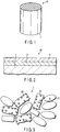
- FIG. 1 is a view schematically showing an exhaust gas-purifying catalyst according to the embodiment of the present invention.
- FIG. 2 is a sectional view schematically showing the exhaust gas-purifying catalyst shown in FIG. 1 .
- the exhaust gas-purifying catalyst 10 is a monolithic catalyst.
- the monolithic catalyst 10 includes a cylindrical support substrate 1 having a honeycomb structure in which a large number of fine through-holes are formed.
- the shape of the support substrate 1 may be a rectangular parallelepiped.
- the support substrate 1 is typically made of ceramics such as cordierite. Alternatively, the support substrate 1 may be made of metal.
- a first catalyst support layer (inner layer) 2 is formed on walls of the support substrate 1, and a second catalyst support layer (outer layer) 3 is formed on the inner layer 2.
- the inner layer 2 and outer layer 3 will be explained below with reference to FIGS. 3 and 4 , respectively.
- FIG. 3 is a view schematically showing the inner layer of the catalyst shown in FIG. 1 .
- FIG. 4 is a view schematically showing the outer layer of the catalyst shown in FIG. 1 .
- the inner layer 2 contains a composite oxide 21 of a rare earth element and zirconium, and alumina 22.
- the inner layer 2 supports a first catalytic metal 23.
- the outer layer 3 contains a composite oxide 31 of a rare earth element and zirconium, and alumina 32.
- the outer layer 3 supports a second catalytic metal 33.
- most of the first catalytic metals 23 are supported by the alumina 22 in FIG. 3
- most of the second catalytic metals 33 are supported by the composite oxide 31 in FIG. 4 .
- the composite oxides 21 and 31 and alumina 22 and 32 which are catalyst supports, increase the specific surface area of the catalytic metals, and suppress sintering of the catalytic metals by radiating the heat generated by the catalytic reaction.
- the atomic ratio R of zirconium to the rare earth element is 0.8 or more.
- the catalytic metals 23 and 33 are different types of precious metals. Examples of the catalytic metals 23 and 33 are rhodium (Rh), platinum (Pt), palladium (Pd), and their mixtures.
- the catalytic metals 23 and 33 accelerate the reducing reaction of NO x and the oxidation reactions of CO and HC.
- the catalytic metal 23 is Pt or Pd, and the catalytic metal 33 is Rh.
- the monolithic catalyst 10 contains only the composite oxides 21 and 31 of a rare earth element and zirconium, in each of which the atomic ratio R of zirconium to the rare earth element is 0.8 or more.
- the monolithic catalyst 10 contains the composite oxides 21 and 31 and does not contain any composite oxide in which the atomic ratio R is lower than 0.8 and any oxide containing only a rare earth element as a metal element, this monolithic catalyst achieves satisfactory exhaust gas purification performance in the HT phase.
- the atomic ratio R typically falls within a range from 1 to 20. If the atomic ratio R is low, the exhaust gas purification performance in the HT phase may become unsatisfactory. If the atomic ratio R is high, the exhaust gas purification performance in the CT phase may become unsatisfactory.
- zirconium contained in the catalyst support layers 2 and 3 generally exists in the form of zirconium oxide.
- 90 wt% or more of zirconium exist in the form of a composite oxide of zirconium and a rare earth element.
- rare-earth element examples include La, Ce, Pr, Nd, Pm, Sm, Eu, Gd, Tb, Dy, Ho, Er, Tm, Yb, Lu, Sc, and Y. It is possible to use only one of rare-earth elements. Alternatively, two or more of rare-earth elements may be used.
- the weight ratios of the alumina 22 and 32 to the composite oxides 21 and 31 in the catalyst support layers 2 and 3 typically fall within a range from 1/200 to 200/1. If the weight ratio of alumina to the composite oxide is low, the catalyst support layer may peel off. If the weight ratio of alumina to the composite oxide is high, the performance of the catalyst in the HT phase tends to deteriorate.
- the weight ratio of alumina to the composite oxide in the catalyst support layer preferably falls within a range from 1/20 to 20/1.
- the weight ratio of alumina to the composite oxide in the inner layer 2 and that in the outer layer 3 may be the same or different.
- the weight ratio in the outer layer 3 may be higher than that in the inner layer 2.
- the exhaust gas-purifying catalyst 10 can be manufactured by, e.g., the following method.
- an aqueous solution of a rare earth element salt and an aqueous solution of a zirconium salt are mixed such that the molar ratio of zirconium to the rare earth element is 0.8 or more.
- an aqueous cerium nitrate solution and an aqueous zirconium nitrate solution are mixed.
- an aqueous ammonia solution is added to the mixture to obtain a coprecipitate of cerium and zirconium. After that, this coprecipitate is fired to obtain composite oxides 21 and 31 of cerium and zirconium.
- the composite oxide 21, a solution containing a catalytic metal salt, and the alumina 22 are mixed to prepare a first slurry.
- the composite oxide 31, a solution containing a catalytic metal salt, and the alumina 32 are mixed to prepare a second slurry.
- the catalytic metal is Pd
- an aqueous palladium nitrate solution or the like can be used as the solution containing a catalytic metal salt.
- the catalytic metal is Rh
- an aqueous rhodium nitrate solution or the like can be used.
- the catalytic metal is Pt, an aqueous dinitrodiamino platinum solution or the like can be used.
- the support substrate 1 is immersed in the first slurry to form a coating film on the surface of the support substrate 1.
- this coating film is dried, another coating film is formed on the surface of the support substrate 1 following the same method as above except that the second slurry is used. This coating film is dried, and fired if necessary. In this manner, the exhaust gas-purifying catalyst 10 is obtained.
- the method of manufacturing the exhaust gas-purifying catalyst 10 is not limited to the above method.
- the exhaust gas-purifying catalyst 10 may be manufactured as follows.
- the alumina 22 and a solution containing a first catalytic metal salt are mixed, and the mixture is dried and fired to obtain alumina 22 which supports the catalytic metal 23.
- the composite oxide 31 obtained as described above and a solution containing a second catalytic metal salt are mixed, and the mixture is dried and fired to obtain a composite oxide 31 which supports the catalytic metal 33.
- the solution containing the first catalytic metal salt is, e.g., an aqueous palladium nitrate solution or aqueous dinitrodiamino platinum solution.
- the solution containing the second catalytic metal salt is, e.g., an aqueous rhodium nitrate solution.
- the composite oxide 21 obtained as described above, the alumina 22 which supports the catalytic metal 23, and water are mixed to prepare a first slurry.
- the composite oxide 31 which supports the catalytic metal 33, the alumina 32, and water are mixed to prepare a second slurry.
- the support substrate 1 is immersed in the first slurry to form a coating film on the surface of the support substrate 1.
- this coating film is dried, another coating film is formed on the surface of the support substrate 1 following the same method as above except that the second slurry is used. This coating film is dried, and fired if necessary. In this manner, the exhaust gas-purifying catalyst 10 is obtained.
- FIG. 2 shows an embodiment in which the number of catalyst support layers is two, the number of catalyst support layers may be one or more than two.
- the present invention is applied to a monolithic catalyst.
- the present invention is applicable to another catalyst.
- a composite oxide X of zirconium and rare earth elements was manufactured by the method explained previously.
- the manufactured composite oxide X contained cerium (Ce), lanthanum (La), and neodymium (Nd) as rare earth elements. Also, a ratio R of the number of zirconium atoms to the sum of the numbers of Ce atoms, La atoms, and Nd atoms was 85/15.
- the monolithic honeycomb support coated with the slurry A was further coated with the slurry B, and the resultant structure dried at 250°C for 1 hr. After that, the resultant structure was fired at 500°C for 1 hr to obtain a catalyst of Example 1.
- the compositions of the obtained catalyst were as follows:
- the monolithic honeycomb support coated with the slurry C was further coated with the slurry B, and the resultant structure was dried at 250°C for 1 hr. After that, the resultant structure was fired at 500°C for 1 hr to obtain a catalyst of Example 2.
- the compositions of the obtained catalyst were as follows:
- a composite oxide Y of zirconium and rare earth elements was manufactured following the same procedures as in Example 1 except that the mixing amount of the rare earth element salts was changed. That is, in this example, the ratio R of the number of zirconium atoms to the sum of the numbers of Ce atoms, La atoms, and Nd atoms was 65/35.
- the monolithic honeycomb support coated with the slurry D was further coated with the slurry B, and the resultant structure was dried at 250°C for 1 hr. After that, the resultant structure was fired at 500°C for 1 hr to obtain a catalyst of Example 3.
- the compositions of the obtained catalyst were as follows:
- the monolithic honeycomb support coated with the slurry E was further coated with the slurry B, and the resultant structure was dried at 250°C for 1 hr. After that, the resultant structure was fired at 500°C for 1 hr to obtain a catalyst of Example 4.
- the compositions of the obtained catalyst were as follows:
- a composite oxide Z of zirconium and rare earth elements was manufactured following the same procedures as in Example 1 except that the mixing amount of the rare earth element salts was changed. That is, in this example, the ratio R of the number of zirconium atoms to the sum of the numbers of Ce atoms, La atoms, and Nd atoms was 45/55.
- a monolithic honeycomb support (volume 1 L) was coated with the slurry F, and the resultant structure was dried at 250°C for 1 hr.
- the monolithic honeycomb support coated with the slurry F was further coated with the slurry B, and the resultant structure was dried at 250°C for 1 hr. After that, the resultant structure was fired at 500°C for 1 hr to obtain a catalyst of Example 5.
- the compositions of the obtained catalyst were as follows:
- a monolithic honeycomb support (volume 1 L) was coated with the slurry G, and the resultant structure was dried at 250°C for 1 hr.
- the monolithic honeycomb support coated with the slurry G was further coated with the slurry B, and the resultant structure was dried at 250°C for 1 hr. After that, the resultant structure was fired at 500°C for 1 hr to obtain a catalyst of Example 6.
- the compositions of the obtained catalyst were as follows:
- This Pd-supporting alumina powder, 100g of the composite oxide X, and water were mixed to prepare a slurry J.
- a monolithic honeycomb support (volume 1 L) was coated with the slurry J, and the resultant structure was dried at 250°C for 1 hr.
- the monolithic honeycomb support coated with the slurry J was further coated with the slurry K, and the resultant structure was dried at 250°C for 1 hr. After that, the resultant structure was fired at 500°C for 1 hr to obtain a catalyst of Example 7.
- the compositions of the obtained catalyst were as follows:
- a composite oxide W of zirconium and rare earth elements was manufactured following the same procedures as in Example 1 except that the mixing amount of the rare earth element salts was changed. That is, in this example, the ratio R of the number of zirconium atoms to the sum of the numbers of Ce atoms, La atoms, and Nd atoms was 25/75.
- a monolithic honeycomb support (volume 1 L) was coated with the slurry H, and the resultant structure was dried at 250°C for 1 hr.
- the monolithic honeycomb support coated with the slurry H was further coated with the slurry B, and the resultant structure was dried at 250°C for 1 hr. After that, the resultant structure was fired at 500°C for 1 hr to obtain a catalyst of Comparative Example 1.
- the compositions of the obtained catalyst were as follows:
- a monolithic honeycomb support (volume 1 L) was coated with the slurry I, and the resultant structure was dried at 250°C for 1 hr.
- the monolithic honeycomb support coated with the slurry I was further coated with the slurry B, and the resultant structure was dried at 250°C for 1 hr. After that, the resultant structure was fired at 500°C for 1 hr to obtain a catalyst of Comparative Example 2.
- the compositions of the obtained catalyst were as follows:
- a composite oxide Q of zirconium and rare earth elements was manufactured following the same procedures as in Example 1 except that the mixing amount of the rare earth element salts was changed. That is, in this example, the ratio R of the number of zirconium atoms to the sum of the numbers of Ce atoms, La atoms, and Nd atoms was 10/90.
- a monolithic honeycomb support (volume 1 L) was coated with the slurry L, and the resultant structure was dried at 250°C for 1 hr.
- the monolithic honeycomb support coated with the slurry L was further coated with the slurry B, and the resultant structure was dried at 250°C for 1 hr. After that, the resultant structure was fired at 500°C for 1 hr to obtain a catalyst of Comparative Example 3.
- the compositions of the obtained catalyst were as follows:
- a monolithic honeycomb support (volume 1 L) was coated with the slurry M, and the resultant structure was dried at 250°C for 1 hr.
- the monolithic honeycomb support coated with the slurry M was further coated with the slurry B, and the resultant structure was dried at 250°C for 1 hr. After that, the resultant structure was fired at 500°C for 1 hr to obtain a catalyst of Comparative Example 4.
- the compositions of the obtained catalyst were as follows:
- Each exhaust gas-purifying catalyst according to Examples 1 to 7 and Comparative Examples 1 to 4 was mounted in an automobile having an engine whose piston displacement was 2.2-L. The automobile was driven in the LA#4 mode, and the HC, CO, and NO x emissions of the automobile were measured.
- the following table shows the emissions of non-methane hydrocarbons (NMHC) obtained for bag1 to bag3.
- NMHC non-methane hydrocarbons
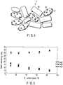
- FIG. 5 the results obtained for the catalysts according to Examples 1 to 6 and Comparative Examples 1 to 4 are summarized in FIG. 5 .
- the ordinate indicates the NMHC emission (mg/mile), and the abscissa indicates the zirconium content (atomic%) in the composite oxide.
- solid rhombus, square, and triangle indicate the results obtained for the catalysts containing Rh and Pt as the catalytic metals
- open rhombus, square, and triangle indicate the results obtained for the catalysts containing Rh and Pd as the catalytic metals.
- LA#4 mode is a test mode in the U.S.A., which is defined in the Federal Test Procedure FTP75. Also, in the table and FIG. 5 , “bag1" indicates the exhaust gases sampled in the CT phase of the test, “bag2” indicates the exhaust gases sampled in the stabilized (S) phase, and “bag3” indicates the exhaust gases sampled in the HT phase.
Landscapes
- Chemical & Material Sciences (AREA)
- Engineering & Computer Science (AREA)
- Chemical Kinetics & Catalysis (AREA)
- Organic Chemistry (AREA)
- Materials Engineering (AREA)
- Health & Medical Sciences (AREA)
- Analytical Chemistry (AREA)
- General Chemical & Material Sciences (AREA)
- Oil, Petroleum & Natural Gas (AREA)
- Environmental & Geological Engineering (AREA)
- Biomedical Technology (AREA)
- Combustion & Propulsion (AREA)
- Catalysts (AREA)
- Exhaust Gas Treatment By Means Of Catalyst (AREA)
- Exhaust Gas After Treatment (AREA)
Applications Claiming Priority (1)
| Application Number | Priority Date | Filing Date | Title |
|---|---|---|---|
| JP2005155780A JP4648089B2 (ja) | 2005-05-27 | 2005-05-27 | 排ガス浄化用触媒 |
Publications (2)
| Publication Number | Publication Date |
|---|---|
| EP1726359A1 EP1726359A1 (en) | 2006-11-29 |
| EP1726359B1 true EP1726359B1 (en) | 2020-04-15 |
Family
ID=36975269
Family Applications (1)
| Application Number | Title | Priority Date | Filing Date |
|---|---|---|---|
| EP06004020.1A Active EP1726359B1 (en) | 2005-05-27 | 2006-02-28 | Exhaust gas-purifying catalyst |
Country Status (3)
| Country | Link |
|---|---|
| US (1) | US20060270549A1 (ja) |
| EP (1) | EP1726359B1 (ja) |
| JP (1) | JP4648089B2 (ja) |
Families Citing this family (26)
| Publication number | Priority date | Publication date | Assignee | Title |
|---|---|---|---|---|
| DE202007019615U1 (de) * | 2006-06-29 | 2014-05-20 | Umicore Ag & Co. Kg | Dreiweg-Katalysator |
| JP5270075B2 (ja) | 2006-07-04 | 2013-08-21 | 株式会社キャタラー | 排ガス浄化用触媒 |
| US8067330B2 (en) * | 2007-02-15 | 2011-11-29 | Mazda Motor Corporation | Catalytic material and catalyst for purifying exhaust gas component |
| DE502007005188D1 (de) * | 2007-03-19 | 2010-11-11 | Umicore Ag & Co Kg | Doppelschichtiger Dreiweg-Katalysator |
| JP2009000648A (ja) * | 2007-06-22 | 2009-01-08 | Toyota Motor Corp | 排ガス浄化用触媒 |
| DE502007002874D1 (de) | 2007-09-28 | 2010-04-01 | Umicore Ag & Co Kg | Entfernung von Partikeln aus dem Abgas von mit überwiegend stöchiometrischem Luft/Kraftstoff-Gemisch betriebenen Verbrennungsmotoren |
| JP5131053B2 (ja) * | 2008-06-24 | 2013-01-30 | トヨタ自動車株式会社 | 貴金属担持触媒及び触媒装置 |
| CN102209587B (zh) * | 2008-11-06 | 2016-07-20 | 株式会社科特拉 | 柴油机用废气净化催化剂和柴油机用废气净化系统 |
| JP5903205B2 (ja) * | 2010-01-04 | 2016-04-13 | 株式会社キャタラー | 排ガス浄化用触媒 |
| US9266092B2 (en) | 2013-01-24 | 2016-02-23 | Basf Corporation | Automotive catalyst composites having a two-metal layer |
| EP3045226B1 (de) | 2015-01-19 | 2024-08-21 | Umicore AG & Co. KG | Doppelschichtiger Dreiweg-Katalysator mit verbesserter Alterungsstabilität |
| US11130117B2 (en) * | 2016-06-13 | 2021-09-28 | Basf Corporation | Catalytic article comprising combined PGM and OSC |
| EP3505245B1 (de) | 2017-12-19 | 2019-10-23 | Umicore Ag & Co. Kg | Katalytisch aktives partikelfilter |
| EP3501648B1 (de) | 2017-12-19 | 2023-10-04 | Umicore Ag & Co. Kg | Katalytisch aktives partikelfilter |
| EP3501647A1 (de) | 2017-12-19 | 2019-06-26 | Umicore Ag & Co. Kg | Katalytisch aktives partikelfilter |
| EP4029592A1 (de) | 2019-03-29 | 2022-07-20 | UMICORE AG & Co. KG | Katalytisch aktives partikelfilter |
| JP7288331B2 (ja) * | 2019-03-29 | 2023-06-07 | 株式会社キャタラー | 排ガス浄化触媒装置 |
| CN111078000B (zh) * | 2019-11-18 | 2023-04-28 | 中北大学 | 一种根据眼行为特征进行眼机交互的方法、装置及系统 |
| DE102020101876A1 (de) | 2020-01-27 | 2021-07-29 | Umicore Ag & Co. Kg | Doppelschichtiger Dreiweg-Katalysator mit weiter verbesserter Alterungsstabilität |
| DE102021118802A1 (de) | 2021-07-21 | 2023-01-26 | Umicore Ag & Co. Kg | Abgasreinigungssystem zur Reinigung von Abgasen von Benzinmotoren |
| DE102021118801A1 (de) | 2021-07-21 | 2023-01-26 | Umicore Ag & Co. Kg | Abgasreinigungssystem zur Reinigung von Abgasen von Benzinmotoren |
| DE102021118803A1 (de) | 2021-07-21 | 2023-01-26 | Umicore Ag & Co. Kg | Abgasreinigungssystem zur Reinigung von Abgasen von Benzinmotoren |
| DE102022130469A1 (de) | 2022-11-17 | 2024-05-23 | Umicore Ag & Co. Kg | Verfahren und Vorrichtung zum Herstellen eines Substrats für eine Abgasnachbehandlungseinrichtung |
| DE102023117464A1 (de) | 2023-07-03 | 2025-01-09 | Umicore Ag & Co. Kg | Verfahren und Vorrichtung zum Herstellen eines Substrats für eine Abgasnachbehandlungseinrichtung |
| DE102023132075A1 (de) | 2023-11-17 | 2025-05-22 | Umicore Ag & Co. Kg | Katalytischer Partikelfilter |
| DE102024115458A1 (de) | 2024-06-04 | 2025-12-04 | Umicore Ag & Co. Kg | Doppelschichtiger Drei-Wege-Katalysator mit deutlich verbessertem CO-Umsatz |
Family Cites Families (12)
| Publication number | Priority date | Publication date | Assignee | Title |
|---|---|---|---|---|
| JPS6388040A (ja) * | 1986-09-30 | 1988-04-19 | Nippon Engeruharudo Kk | 車輌用排気ガス浄化用触媒及びその製造方法 |
| US5015617A (en) * | 1988-04-14 | 1991-05-14 | Nippon Shokubai Kagaku Kogyo Co., Ltd. | Catalyst for purifying exhaust gas and method for production thereof |
| ES2071099T3 (es) * | 1989-06-09 | 1995-06-16 | N E Chemcat Corp | Catalizador de la purificacion de gases de escape con excelente resistencia termica y metodo de produccion del mismo. |
| US5057483A (en) * | 1990-02-22 | 1991-10-15 | Engelhard Corporation | Catalyst composition containing segregated platinum and rhodium components |
| JP2734808B2 (ja) * | 1991-05-10 | 1998-04-02 | 日産自動車株式会社 | 排ガス浄化用触媒 |
| JPH0760117A (ja) * | 1993-08-30 | 1995-03-07 | Honda Motor Co Ltd | 排気ガス浄化用触媒 |
| JP4053623B2 (ja) * | 1996-12-27 | 2008-02-27 | 阿南化成株式会社 | ジルコニウム−セリウム系複合酸化物及びその製造方法 |
| US5888464A (en) * | 1997-04-08 | 1999-03-30 | Engelhard Corporation | Catalyst composition containing an intimately combined cerium-zirconium oxide |
| DE10024994A1 (de) * | 1999-05-24 | 2001-01-04 | Daihatsu Motor Co Ltd | Katalytischer Umwandler zum Reinigen von Abgasen |
| US6846466B2 (en) * | 2000-03-22 | 2005-01-25 | Cataler Corporation | Catalyst for purifying an exhaust gas |
| JP3851521B2 (ja) * | 2000-09-26 | 2006-11-29 | ダイハツ工業株式会社 | 排ガス浄化用触媒 |
| GB2376903A (en) * | 2001-04-05 | 2002-12-31 | Johnson Matthey Plc | Nitrogen oxides emission control under lean-burn conditions |
-
2005
- 2005-05-27 JP JP2005155780A patent/JP4648089B2/ja not_active Expired - Fee Related
-
2006
- 2006-02-28 EP EP06004020.1A patent/EP1726359B1/en active Active
- 2006-03-02 US US11/367,179 patent/US20060270549A1/en not_active Abandoned
Non-Patent Citations (1)
| Title |
|---|
| None * |
Also Published As
| Publication number | Publication date |
|---|---|
| JP2006326527A (ja) | 2006-12-07 |
| US20060270549A1 (en) | 2006-11-30 |
| JP4648089B2 (ja) | 2011-03-09 |
| EP1726359A1 (en) | 2006-11-29 |
Similar Documents
| Publication | Publication Date | Title |
|---|---|---|
| EP1726359B1 (en) | Exhaust gas-purifying catalyst | |
| EP3260189B1 (en) | Exhaust gas purifying catalyst | |
| EP1438135B1 (en) | Layered catalyst composite and use thereof | |
| EP1810738B1 (en) | Catalyst for exhaust gas purification | |
| EP1332787B1 (en) | Catalyst for purifying exhaust gases | |
| EP1938895A1 (en) | Catalyst containing little or no rhodium for purifying exhaust gases of internal combustion engine | |
| EP3885030A1 (en) | Exhaust gas purification catalyst | |
| EP2075062A1 (en) | Exhaust gas purification catalyst | |
| KR101147055B1 (ko) | 배기 가스 정화용 촉매 | |
| EP2992955B1 (en) | Exhaust-gas purification catalyst | |
| JP6339013B2 (ja) | 排気ガス浄化触媒用担体、排気ガス浄化用触媒及び排気ガス浄化用触媒構成体 | |
| EP1743696A1 (en) | Exhaust gas clarification catalyst | |
| EP3978115A1 (en) | Exhaust gas purification catalyst and exhaust gas purification system using said exhaust gas purification catalyst | |
| EP1721655B1 (en) | Hydrogen sulfide generation-suppressed catalyst | |
| EP4295941A1 (en) | Exhaust gas purification catalyst | |
| EP4349479A1 (en) | Exhaust gas purification catalyst | |
| EP4316650A1 (en) | Exhaust gas purifying catalyst and exhaust gas purification system | |
| EP4574257A1 (en) | Catalyst for exhaust gas purification | |
| EP4406645A1 (en) | Exhaust gas purification catalyst, and exhaust gas purification catalyst device for vehicles | |
| EP4474047B1 (en) | Exhaust gas purification catalyst | |
| EP4316651B1 (en) | Exhaust gas purification catalyst | |
| EP4477296A1 (en) | Exhaust gas purification catalytic device | |
| JPH11267505A (ja) | 排気ガス浄化用触媒の製造方法 | |
| JPH1076162A (ja) | 排気ガス浄化用触媒 | |
| JP2004058001A (ja) | 排気ガス浄化用触媒及びその製造方法 |
Legal Events
| Date | Code | Title | Description |
|---|---|---|---|
| PUAI | Public reference made under article 153(3) epc to a published international application that has entered the european phase |
Free format text: ORIGINAL CODE: 0009012 |
|
| AK | Designated contracting states |
Kind code of ref document: A1 Designated state(s): AT BE BG CH CY CZ DE DK EE ES FI FR GB GR HU IE IS IT LI LT LU LV MC NL PL PT RO SE SI SK TR |
|
| AX | Request for extension of the european patent |
Extension state: AL BA HR MK YU |
|
| 17P | Request for examination filed |
Effective date: 20070321 |
|
| 17Q | First examination report despatched |
Effective date: 20070423 |
|
| AKX | Designation fees paid |
Designated state(s): DE FR GB |
|
| STAA | Information on the status of an ep patent application or granted ep patent |
Free format text: STATUS: EXAMINATION IS IN PROGRESS |
|
| GRAP | Despatch of communication of intention to grant a patent |
Free format text: ORIGINAL CODE: EPIDOSNIGR1 |
|
| STAA | Information on the status of an ep patent application or granted ep patent |
Free format text: STATUS: GRANT OF PATENT IS INTENDED |
|
| INTG | Intention to grant announced |
Effective date: 20191120 |
|
| GRAS | Grant fee paid |
Free format text: ORIGINAL CODE: EPIDOSNIGR3 |
|
| GRAA | (expected) grant |
Free format text: ORIGINAL CODE: 0009210 |
|
| STAA | Information on the status of an ep patent application or granted ep patent |
Free format text: STATUS: THE PATENT HAS BEEN GRANTED |
|
| REG | Reference to a national code |
Ref country code: DE Ref legal event code: R081 Ref document number: 602006059312 Country of ref document: DE Owner name: CATALER CORPORATION, KAKEGAWA-SHI, JP Free format text: FORMER OWNER: CATALER CORP., SHIZUOKA, JP |
|
| AK | Designated contracting states |
Kind code of ref document: B1 Designated state(s): DE FR GB |
|
| REG | Reference to a national code |
Ref country code: GB Ref legal event code: FG4D |
|
| REG | Reference to a national code |
Ref country code: DE Ref legal event code: R096 Ref document number: 602006059312 Country of ref document: DE |
|
| REG | Reference to a national code |
Ref country code: DE Ref legal event code: R097 Ref document number: 602006059312 Country of ref document: DE |
|
| PLBE | No opposition filed within time limit |
Free format text: ORIGINAL CODE: 0009261 |
|
| STAA | Information on the status of an ep patent application or granted ep patent |
Free format text: STATUS: NO OPPOSITION FILED WITHIN TIME LIMIT |
|
| 26N | No opposition filed |
Effective date: 20210118 |
|
| PGFP | Annual fee paid to national office [announced via postgrant information from national office to epo] |
Ref country code: DE Payment date: 20250220 Year of fee payment: 20 |
|
| PGFP | Annual fee paid to national office [announced via postgrant information from national office to epo] |
Ref country code: FR Payment date: 20250228 Year of fee payment: 20 |
|
| PGFP | Annual fee paid to national office [announced via postgrant information from national office to epo] |
Ref country code: GB Payment date: 20250204 Year of fee payment: 20 |