EP1721518A1 - Régulation d'un organe d'alimentation d'une machine de travail agricole - Google Patents
Régulation d'un organe d'alimentation d'une machine de travail agricole Download PDFInfo
- Publication number
- EP1721518A1 EP1721518A1 EP06004359A EP06004359A EP1721518A1 EP 1721518 A1 EP1721518 A1 EP 1721518A1 EP 06004359 A EP06004359 A EP 06004359A EP 06004359 A EP06004359 A EP 06004359A EP 1721518 A1 EP1721518 A1 EP 1721518A1
- Authority
- EP
- European Patent Office
- Prior art keywords
- hydraulic
- hydraulic circuit
- agricultural machine
- hydraulically driven
- circuit intake
- Prior art date
- Legal status (The legal status is an assumption and is not a legal conclusion. Google has not performed a legal analysis and makes no representation as to the accuracy of the status listed.)
- Granted
Links
- 210000000056 organ Anatomy 0.000 claims description 29
- 230000005540 biological transmission Effects 0.000 claims description 6
- 238000011156 evaluation Methods 0.000 claims description 6
- 239000012530 fluid Substances 0.000 claims description 6
- 230000001419 dependent effect Effects 0.000 claims description 4
- 238000006243 chemical reaction Methods 0.000 claims description 3
- 238000010926 purge Methods 0.000 claims description 3
- 230000004044 response Effects 0.000 claims description 3
- 238000011144 upstream manufacturing Methods 0.000 claims description 3
- 238000011010 flushing procedure Methods 0.000 claims description 2
- 239000010720 hydraulic oil Substances 0.000 claims 2
- 239000003921 oil Substances 0.000 claims 1
- ZZUFCTLCJUWOSV-UHFFFAOYSA-N furosemide Chemical compound C1=C(Cl)C(S(=O)(=O)N)=CC(C(O)=O)=C1NCC1=CC=CO1 ZZUFCTLCJUWOSV-UHFFFAOYSA-N 0.000 abstract 1
- 230000006835 compression Effects 0.000 description 14
- 238000007906 compression Methods 0.000 description 14
- 238000000034 method Methods 0.000 description 6
- 230000008569 process Effects 0.000 description 6
- 238000007789 sealing Methods 0.000 description 5
- 238000001514 detection method Methods 0.000 description 4
- 230000008901 benefit Effects 0.000 description 3
- 239000004459 forage Substances 0.000 description 3
- 238000006073 displacement reaction Methods 0.000 description 2
- 230000001133 acceleration Effects 0.000 description 1
- 230000004913 activation Effects 0.000 description 1
- 230000001174 ascending effect Effects 0.000 description 1
- 230000000903 blocking effect Effects 0.000 description 1
- 238000001816 cooling Methods 0.000 description 1
- 239000011162 core material Substances 0.000 description 1
- 230000006378 damage Effects 0.000 description 1
- 238000005553 drilling Methods 0.000 description 1
- 230000000694 effects Effects 0.000 description 1
- 238000001914 filtration Methods 0.000 description 1
- 230000009347 mechanical transmission Effects 0.000 description 1
- 239000002184 metal Substances 0.000 description 1
- 230000035484 reaction time Effects 0.000 description 1
- 230000009467 reduction Effects 0.000 description 1
- 230000009528 severe injury Effects 0.000 description 1
- 230000001960 triggered effect Effects 0.000 description 1
Images


Classifications
-
- F—MECHANICAL ENGINEERING; LIGHTING; HEATING; WEAPONS; BLASTING
- F16—ENGINEERING ELEMENTS AND UNITS; GENERAL MEASURES FOR PRODUCING AND MAINTAINING EFFECTIVE FUNCTIONING OF MACHINES OR INSTALLATIONS; THERMAL INSULATION IN GENERAL
- F16H—GEARING
- F16H61/00—Control functions within control units of change-speed- or reversing-gearings for conveying rotary motion ; Control of exclusively fluid gearing, friction gearing, gearings with endless flexible members or other particular types of gearing
- F16H61/38—Control of exclusively fluid gearing
- F16H61/40—Control of exclusively fluid gearing hydrostatic
- F16H61/4157—Control of braking, e.g. preventing pump over-speeding when motor acts as a pump
-
- A—HUMAN NECESSITIES
- A01—AGRICULTURE; FORESTRY; ANIMAL HUSBANDRY; HUNTING; TRAPPING; FISHING
- A01D—HARVESTING; MOWING
- A01D75/00—Accessories for harvesters or mowers
- A01D75/18—Safety devices for parts of the machines
- A01D75/187—Removing foreign objects
-
- F—MECHANICAL ENGINEERING; LIGHTING; HEATING; WEAPONS; BLASTING
- F16—ENGINEERING ELEMENTS AND UNITS; GENERAL MEASURES FOR PRODUCING AND MAINTAINING EFFECTIVE FUNCTIONING OF MACHINES OR INSTALLATIONS; THERMAL INSULATION IN GENERAL
- F16H—GEARING
- F16H61/00—Control functions within control units of change-speed- or reversing-gearings for conveying rotary motion ; Control of exclusively fluid gearing, friction gearing, gearings with endless flexible members or other particular types of gearing
- F16H61/38—Control of exclusively fluid gearing
- F16H61/40—Control of exclusively fluid gearing hydrostatic
- F16H61/4043—Control of a bypass valve
-
- F—MECHANICAL ENGINEERING; LIGHTING; HEATING; WEAPONS; BLASTING
- F16—ENGINEERING ELEMENTS AND UNITS; GENERAL MEASURES FOR PRODUCING AND MAINTAINING EFFECTIVE FUNCTIONING OF MACHINES OR INSTALLATIONS; THERMAL INSULATION IN GENERAL
- F16H—GEARING
- F16H61/00—Control functions within control units of change-speed- or reversing-gearings for conveying rotary motion ; Control of exclusively fluid gearing, friction gearing, gearings with endless flexible members or other particular types of gearing
- F16H61/38—Control of exclusively fluid gearing
- F16H61/40—Control of exclusively fluid gearing hydrostatic
- F16H61/4078—Fluid exchange between hydrostatic circuits and external sources or consumers
- F16H61/4104—Flushing, e.g. by using flushing valves or by connection to exhaust
-
- Y—GENERAL TAGGING OF NEW TECHNOLOGICAL DEVELOPMENTS; GENERAL TAGGING OF CROSS-SECTIONAL TECHNOLOGIES SPANNING OVER SEVERAL SECTIONS OF THE IPC; TECHNICAL SUBJECTS COVERED BY FORMER USPC CROSS-REFERENCE ART COLLECTIONS [XRACs] AND DIGESTS
- Y10—TECHNICAL SUBJECTS COVERED BY FORMER USPC
- Y10S—TECHNICAL SUBJECTS COVERED BY FORMER USPC CROSS-REFERENCE ART COLLECTIONS [XRACs] AND DIGESTS
- Y10S56/00—Harvesters
- Y10S56/11—Hydraulic
Definitions
- the invention relates to an agricultural machine with hydraulically driven by a hydraulic circuit intake members according to the preamble of claim 1.
- Such a system is among others from the DE 100 36 612 A1 known.
- the hydraulically driven, designed as paired feed rollers feeders between them promote a Erntegutstrom which is passed in its rear region to a Emtegutzerklein mecanics issued, such as a cutterhead.
- the Emtegutstrom is often interspersed by foreign bodies, such as metal parts or stones, which can cause severe damage to the rotating at high speed cutterhead, the catchment organs is associated with a so-called quick stop function.
- the foreign bodies embedded in the crop stream are determined by means of a detection device and, depending on their detection, a switch-off signal for the intake elements is generated in a control device.
- the switching valve arrangement comprises at least one brake function for the at least one hydraulic motor and the brake function realizing portion of the hydraulic circuit is substantially free of elasticities, it is ensured that upon detection of foreign bodies in Emtegutstrang an abrupt halting of the intake and pre-compression rollers is possible because elasticity-induced inertia need not be overcome.
- the switching valve arrangement in the operating state "normal operation" allows pressurization of the engine and flushing of the hydraulic medium.
- a particularly advantageous embodiment of the invention results when the switching valve arrangement in the operating state "rapid stop" passes through a working cycle in which in a first step, the promotion of the hydraulic medium to the hydraulic motor is at least partially interrupted, in a further step, the purging of the hydraulic medium is adjusted and in at least a third step, the deceleration of the hydraulic motor takes place.
- a single valve arrangement allows the execution of the entire operating state "rapid stop”.
- a structurally simple, compact and effective implementation of the operating state "rapid stop" results when the switching valve arrangement is designed as a continuous valve, the valve piston is controlled by controlling at least two Steuerzylindem in its movement.
- control cylinders are independently controllable.
- the valve piston which realizes the steps of the work cycle in the operating state "rapid stop” comprises a piston surface which is contacted by the cylindrical surfaces of the at least two control cylinders on opposite sides. In this way, the valve piston can be guided reliably and in a structurally simple manner by the control cylinders.
- the switching off of the switching valve arrangement of the operating state "normal operation” in the operating state “rapid stop” is effected by switching off the control pressure of the other control cylinder.
- a brake valve is assigned in such a way that the rotational movement of the hydraulic pump and standing in operative connection with them working bodies is decelerated ,
- the at least two control cylinders of the switching valve assembly in the operating state "normal operation” and at least partially during the execution of the third step of the duty cycle of the switching valve assembly in the operating state "rapid stop” in equilibrium are advantageous embodiments of the invention.
- the equilibrium state between the Steuerzylindem in the operating state "normal operation" can be achieved in that the cylinder surface ratios of the control cylinder are matched and / or the pressurization of the control cylinder with controlled pressures of the hydraulic medium takes place.
- a secure hold of the equilibrium state in the operating state "rapid stop" is achieved in an advantageous embodiment of the invention, if substantially at the end of the third step of the working cycle, the resulting pressure force of the pressurized control cylinder in equilibrium with that of the differential surface of the valve piston and one on the valve piston acting dynamic pressure dependent reaction force is.
- the first step of the duty cycle of the continuous valve according to the invention is realized in that the lock cylinder is associated with a bypass piston whose at least one bypass hole during the movement of the valve piston in the first step of the work cycle opens a bypass line on the at least a portion of the hydraulic fluid flowing to the hydraulic medium is derived.
- the bypass line can be assigned a check valve in an advantageous embodiment of the invention. that the pressure source can supply the hydraulic circuit with hydraulic medium during the rapid stop process, while in normal operation the check valve is closed.
- valve piston on a diaphragm which interrupts the connection between the working port and a Spülölkanal during the movement of the valve piston in the second step of the working cycle.
- the valve piston on one choke slots which close during the movement of the valve piston in the third step of the work cycle, the return line from the hydraulic motor to the hydraulic pump, wherein the nachgeletterte of the hydraulic pump hydraulic fluid back pressure builds up for braking the hydraulic motor, which is preferably in the range of the permissible operating pressure.
- valve piston a plurality of throttle bodies are assigned in such a way that depending on the piston piston travel from the piston the free passage cross section for the hydraulic medium changes continuously.
- control cylinders do not impinge unopposed at high speed on the respective stops are in a further advantageous embodiment of the invention the at least two control cylinders control edges and / or throttle points are assigned in such a way that the movement of the valve piston is braked in the end regions.
- the drive according to the invention has a compact, space-saving form and at the same time may be free of elasticities, such as long hose lines are in an advantageous embodiment of the invention, the hydraulic motor, the hydraulic pump, the switching valve assembly and for controlling the hydraulic motor, the hydraulic pump and the Schalfirentilan Aunt in the operating states "normal operation” and “quick stop” necessary switching valves are combined in a drive unit forming the drive train drive block.
- a high flexibility in the design of the drive in normal, quick stop and Reversier americanados for the intake and pre-compression rollers and the feed and pre-compression rollers upstream cross-conveying the attachment then becomes achieved when the intake members are coupled to at least one mechanical distribution gear, the input shaft to the hydraulic drive (13) is coupled and wherein the mechanical transmission also has a further transmission output and the other transmission output is coupled to the cross conveyor of the attachment.
- Figure 1 shows an executed as a self-propelled forage harvester 2 agricultural machine 1, which is assigned in its front area as a so-called pick-up 4 running attachment 3.
- the attachment 3 takes in the illustrated embodiment, lying on the bottom 5 Emtegutstrang 6 by means of a collection device 7, this compacts by means of a hold-down assembly 8 and leads the Erntegutstrang 6 finally via a cross conveyor 9 the attachment 3 downstream feeder and Vvrpresswalzen 10.
- the intake and pre-compression rollers 10 are received in pairs by a feeder housing 11.
- the feed and pre-press rolls 10 arranged in pairs are actively driven in accordance with the direction of the arrow 12 by means of a drive 13 which will be described later.
- the compacted crop strand 6 enters the rear region of the intake housing 11 above a counter-blade 14 in the effective range of the chopping blade 15 an actively driven, rotating chopper drum 16 a.
- the crushed Erntegutstrang 6 finally occurs at high speed in the rear region of the cutterhead from this in an ascending Chute 17, in which the Erntegutstrang 6 is conveyed by means of a so-called Nachbeschreibers 18 from the forage harvester 2 out on a not shown loading vehicle.
- the front-side feed roller pair 20 is associated with a known foreign body locating device 21. If the foreign body 19 stored in the core material strand 6 is conveyed into the region of the foreign body locating device 21, this generates a locating signal X which is fed to an evaluation and control unit 22 and generates therein a so-called quick stop signal Y, which generates the drive 13 of the feeder to be described in more detail - And pre-press rolls 10 turns off.
- the operator 23 of the agricultural machine 1 via an input terminal 24 a reversing signal Z in the evaluation and control unit 22 trigger, which triggers a reversing of the drive 13 and coupled with him feed and pre-compression rollers 10.
- the detected foreign body 19 is again conveyed out of the region of the intake and pre-compression rollers 10 and can finally be removed from the crop train 6 by the operator 23.
- the described reversing process can also be triggered automatically after the infeed and pre-press rolls 10 have come to a standstill.
- a first drive belt system 25 transmits the drive energy of the motor 26 to, among other things, the chopper drum 16, from which another belt system 27 drives a hydraulic motor-pump unit 28, which finally the continuously variable hydraulic drive 13 of the intake and pre-compression rollers 10 forms.
- the output shaft 29 of the motor-pump unit 28 is assigned via a propeller shaft 30, a mechanical distribution gear 31, which initially drives each of the intake and pre-compression rollers 10 in a conventional manner.
- the distribution gear 31 has a further transmission output 32, which directly drives the feed and pre-press rollers 12 upstream cross conveyor 9 of the attachment 3.
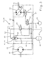
- FIG. 3 shows the motor-pump unit 28 in a schematic detail.
- the hydraulic motor 40 and the hydraulic pump 41 are connected via a line system 42, in which the inventive, designed as a continuous valve 43 switching valve assembly 44 is integrated.
- the motor-pump unit 28 is also integrated in a hydraulic circuit 45, which comprises a known manner as a so-called pressure source running hydraulic pump 46, a tank 47 for storing the hydraulic medium and a pressure accumulator 48.
- the hydraulic circuit 45 operates because of the existing external pressure source 46 as a so-called constant pressure circuit.
- the further electrohydraulic switching valves 49-51 integrated in the hydraulic circuit 45 and the mode of operation of the hydraulic circuit 45 are described in greater detail in connection with the simplified sectional illustration of the switching valve arrangement 44 according to the invention shown in FIG.
- the hydraulic circuit 45 In order for the hydraulic circuit 45 according to the invention to permit an abrupt stop of the intake elements designed as intake and pre-compression rollers 10, at least the hydraulic motor 40, the hydraulic pump 41 and the required switching valves 43, 49-51 are combined in a drive block 33 forming the drive 13, wherein the individual elements 40, 41, 43, 49-51 of the hydraulic circuit 45 are flanged directly to each other and / or interconnected by piping systems. In addition, the switching valves 43, 49-51 of the hydraulic circuit 45 become switched electrohydraulically.
- Such an embodiment has the particular advantage that at least in the area of the hydraulic circuit 45 that realizes the braking of the drive 13 there are neither hose lines nor spring-based valve controls whose elastic properties, such as the pressure-dependent stretching of hose lines and the inertia of spring-based systems, are abrupt Braking the drive 13 of the intake and pre-compression rollers 10 would oppose.
- the continuous valve 43 has terminal housing sections 52, 53 which are penetrated by bores 54 in which control cylinders 55, 56 are displaceably arranged, the movement of the control cylinders 55, 56 being limited by end stops 57.
- At their end faces facing each other take the control cylinder 55, 56 between them a piston surface 58 on the displacement of the control cylinder 55, 56 at the same time to a displacement of the valve piston 59 within the continuous valve 43 leads.
- the "normal operation” the control cylinders 55, 56 are acted upon in their rear regions independently of one another by control pressure lines 60 with a defined control pressure which keeps the valve piston 58 in an equilibrium position according to FIG.
- the operating state "normal operation” is maintained until a foreign body 19 is detected at the foreign body locating device 21 and the rapid stop signal Y is generated in the evaluation and control unit 22 and in the operating state "Quick stop” is switched.
- the rapid stop signal Y leads to the switching of the Stetigventil 43 associated Schnellstoppschaltventils 49 in the position shown in Figure 3.
- the upper control cylinder 56 is depressurized by the hydraulic medium via the pressure line 60 and the associated Schnellstoppschaltventil 49 is discharged into the tank 47.
- the upper control cylinder 56 acts as an opening cylinder.
- the further pressurized lower control cylinder 55 operates in the operating state "quick stop" as a lock cylinder and moves the valve piston 59 in the direction of arrow 65 by the continuous valve 43 according to the invention.
- the piston surface 58 of the valve piston 59 associated front region of the lower control cylinder 55 takes a by bypass bores 66 interspersed by-pass piston 66 on.
- the movement of the lower control cylinder 55 moves the bypass piston 66 in a first step into the region of the pressure line leading to the hydraulic motor 40.
- the hydraulic medium flows bypassing the hydraulic motor 40 via a bypass line 64 back to the hydraulic pump 41, so that the supply of the hydraulic motor 40 with collapses pressurized hydraulic fluid, thus the hydraulic motor 40 is turned off.
- the further movement of the valve piston 59 according to arrow direction 65 closes in a further step by means of an integrally formed on the Vontilkolben 59 aperture 68 the Spülölkanal 63, so that no more hydraulic medium can be dissipated via this.
- the further movement of the valve piston 59 according to arrow 65 leads to the sudden braking of the hydraulic motor 40 and thus to a standstill of the intake and pre-compression rollers 10 by the valve piston 59, the return line 62 from the hydraulic motor 40 to the hydraulic pump 41 closes.
- the hydraulic pump 41 further promotes hydraulic fluid to the hydraulic motor 40, but this can no longer flow, builds up in the pressure line 61 to the hydraulic motor 40 abruptly a back pressure, which stops the hydraulic motor 40 and coupled with him feed and pre-compression rollers 10 abruptly. So that the build-up dynamic pressure does not lead to an overload of the organs acted upon by him, which is acting as opening cylinder control cylinder 56 associated end of the valve piston 59 of Drvsselschlitzen 69 passes through the excess hydraulic fluid from the engine return 62 can flow.
- the throttle slots 69, the control cylinder 55, 56th and the valve piston 59 dimensioned so that adjusts a back pressure, which is in the range of the operating pressure of the hydraulic circuit 25 and preferably 350 bar.
- the movement of the lock cylinder 55 according to arrow direction 65 also leads to a continuous reduction of the passage cross section of the throttle slots 69.
- the differential surface of the valve piston 59 is dimensioned so that the valve piston 59 is then in equilibrium with the pressurized lock cylinder 55 when the back pressure reaches a defined value, has reached 350 bar in the illustrated embodiment. This ensures the safe holding of the brake function in a simple manner.
- the valve piston 59 of the continuous valve 43 is assigned a check valve 70 in the form of a sealing disk 73 which can be moved by the hydraulic medium.
- the sealing disk 73 is arranged in a freely movable manner between the piston surface of the valve piston 59 contacted by the jam cylinders 55, 56 and an adjusting ring 74 fitted in the valve piston 59 and is pressed against the adjusting ring 74 or the valve piston 59 depending on the direction of flow of the hydraulic medium.
- the check valve 70 In the operating state "normal operation", the check valve 70 is closed because the hydraulic medium flowing back from the hydraulic motor 40 to the hydraulic pump 41 via the return line 62 pressurizes the sealing disk 73 in the direction of the piston surface of the valve piston 59 and thus in the closing direction.
- the hydraulic pump 46 operating as a pressure source conveys a pressure oil flow in the opening direction of the check valve 70, in which the sealing washer 73 rests against the adjusting ring 74, so that during the operating mode "rapid stop” the control oil flow generated by the hydraulic pump 46 into the hydraulic circuit 45 of the invention arrives, so that in this also during the braking process, the so-called feed pressure is maintained.
- the hydraulic pump 41 may also be assigned a designed as an electrohydraulic switching valve brake valve 51 which decelerates the coupled via an external drive 71 to the hydraulic pump 41 Humbleseltrommel 16 after switching off its drive.
- This has the effect, in particular, that long follow-up times of the shut-off cutterhead 16 avoided.
- the triggering of the braking function can be achieved, for example, that the pressure source switching valve 50 switches the brake valve 51 by means of a control pressure in the blocking position, so that the rotational movement of the hydraulic pump 41 blocks and thus the chopper drum 16 is suddenly decelerated to a standstill.
- control cylinder 56 designed as an opening cylinder is assigned a throttle cross-section 72 at the top, via which the hydraulic medium displaced by the control cylinder 56 is discharged.
- the control cylinder 56 is braked before it reaches the stop 57 assigned to it and reaches the stop 57 with little impact.
Landscapes
- Engineering & Computer Science (AREA)
- General Engineering & Computer Science (AREA)
- Mechanical Engineering (AREA)
- Life Sciences & Earth Sciences (AREA)
- Environmental Sciences (AREA)
- Fluid-Pressure Circuits (AREA)
- Lifting Devices For Agricultural Implements (AREA)
- Guiding Agricultural Machines (AREA)
- Harvester Elements (AREA)
- Catching Or Destruction (AREA)
Applications Claiming Priority (1)
| Application Number | Priority Date | Filing Date | Title |
|---|---|---|---|
| DE102005023047A DE102005023047A1 (de) | 2005-05-13 | 2005-05-13 | Einzugsorgansteuerung für landwirtschaftliche Arbeitsmaschine |
Publications (2)
| Publication Number | Publication Date |
|---|---|
| EP1721518A1 true EP1721518A1 (fr) | 2006-11-15 |
| EP1721518B1 EP1721518B1 (fr) | 2009-09-23 |
Family
ID=36586158
Family Applications (1)
| Application Number | Title | Priority Date | Filing Date |
|---|---|---|---|
| EP06004359A Not-in-force EP1721518B1 (fr) | 2005-05-13 | 2006-03-03 | Régulation d'un organe d'alimentation d'une machine de travail agricole |
Country Status (4)
| Country | Link |
|---|---|
| US (1) | US7464525B2 (fr) |
| EP (1) | EP1721518B1 (fr) |
| AT (1) | ATE443436T1 (fr) |
| DE (2) | DE102005023047A1 (fr) |
Cited By (4)
| Publication number | Priority date | Publication date | Assignee | Title |
|---|---|---|---|---|
| EP2132973A1 (fr) | 2008-06-13 | 2009-12-16 | Deere & Company | Système d'entraînement pour une machine de récolte |
| WO2010003966A1 (fr) * | 2008-07-11 | 2010-01-14 | Deere & Company | Système d'entraînement pour un transporteur d'alimentation de moissonneuse |
| EP2145527A2 (fr) * | 2008-07-18 | 2010-01-20 | GKN Walterscheid GmbH | Agencement d'entraînement pour une machine de travail agricole |
| DE102012107227A1 (de) | 2012-08-07 | 2014-02-13 | Linde Hydraulics Gmbh & Co. Kg | Antriebssystem zum Antrieb einer Häcksel- und Einzugsvorrichtung einer Erntemaschine |
Families Citing this family (8)
| Publication number | Priority date | Publication date | Assignee | Title |
|---|---|---|---|---|
| DE102007025310A1 (de) * | 2007-05-30 | 2008-12-04 | Claas Selbstfahrende Erntemaschinen Gmbh | Landwirtschaftliche Erntemaschine mit einer Fremdkörpererkennungsvorrichtung |
| DE102009035571A1 (de) * | 2009-07-31 | 2011-02-03 | Hydac System Gmbh | Hydrostatischer Antrieb |
| GB2479566A (en) * | 2010-04-15 | 2011-10-19 | Agco Int Gmbh | Braking system for a rotating chopper drum of a forage harvester |
| DE102012218546A1 (de) * | 2012-10-11 | 2014-04-17 | Putzmeister Engineering Gmbh | Hydraulisches Antriebssystem und Verfahren zum Antrieb eines Bandförderers |
| BE1022404B1 (nl) * | 2013-12-16 | 2016-03-24 | Cnh Industrial Belgium Nv | Gewasopraper, landbouwwerktuig en werkwijze voor het uitwerpen van een vreemd object |
| US9915192B2 (en) * | 2014-08-04 | 2018-03-13 | Jeffrey J. Buschur | Power conversion device |
| US9510514B2 (en) * | 2015-04-14 | 2016-12-06 | Deere & Company | Lockout closure mechanism for agricultural vehicle |
| CN106922318A (zh) * | 2017-02-17 | 2017-07-07 | 山东省农业机械科学研究院 | 生物质粉碎机 |
Citations (6)
| Publication number | Priority date | Publication date | Assignee | Title |
|---|---|---|---|---|
| EP0567851A1 (fr) * | 1992-04-30 | 1993-11-03 | Claas Saulgau Gmbh | Dispositif d'entraînement des rouleaux d'amenée d'une récolteuse-hacheuse |
| DE10021663A1 (de) | 2000-05-04 | 2001-11-15 | Krone Bernhard Gmbh Maschf | Erntemaschine, insbesondere selbstfahrender Feldhäcksler |
| DE10036612A1 (de) | 2000-07-27 | 2002-02-14 | Case Harvesting Sys Gmbh | Feldhäcksler mit hydraulisch angetriebenen Einzugsorganen |
| US6388860B1 (en) * | 2000-02-17 | 2002-05-14 | Deere & Company | Dual switch control system |
| US20030080305A1 (en) * | 2001-10-26 | 2003-05-01 | Ina-Schaeffler Kg | Electromagnet, in particular a proportional magnet for operating a hydraulic valve |
| US20030172638A1 (en) * | 2000-03-06 | 2003-09-18 | Ameye Danny R | Feeder controls for a forage harvester |
Family Cites Families (7)
| Publication number | Priority date | Publication date | Assignee | Title |
|---|---|---|---|---|
| US3736753A (en) * | 1971-09-22 | 1973-06-05 | Deere & Co | Hydraulic drive |
| JPS63134869A (ja) * | 1986-11-25 | 1988-06-07 | Daikin Ind Ltd | 可変容量形ピストン機械 |
| JPH02212670A (ja) * | 1989-02-10 | 1990-08-23 | Honda Motor Co Ltd | 変速機のクラッチ制御装置 |
| DE19904626C2 (de) * | 1999-02-05 | 2001-05-17 | Case Harvesting Sys Gmbh | Verfahren zum Erkennen von Fremdkörpern in Erntemaschinen |
| DE19955901A1 (de) * | 1999-11-20 | 2001-05-23 | Deere & Co | Vorrichtung zur Arretierung einer Ernteguttransportvorrichtung |
| JP2001349426A (ja) * | 2000-06-05 | 2001-12-21 | Komatsu Ltd | 油圧ポンプの容量制御装置および油圧モータのブレーキ制御装置 |
| US7022012B2 (en) * | 2004-09-02 | 2006-04-04 | Cnh America Llc | Sensitivity adjustment for stone detection system |
-
2005
- 2005-05-13 DE DE102005023047A patent/DE102005023047A1/de not_active Withdrawn
-
2006
- 2006-03-03 AT AT06004359T patent/ATE443436T1/de active
- 2006-03-03 EP EP06004359A patent/EP1721518B1/fr not_active Not-in-force
- 2006-03-03 DE DE502006004898T patent/DE502006004898D1/de active Active
- 2006-05-09 US US11/430,777 patent/US7464525B2/en not_active Expired - Fee Related
Patent Citations (6)
| Publication number | Priority date | Publication date | Assignee | Title |
|---|---|---|---|---|
| EP0567851A1 (fr) * | 1992-04-30 | 1993-11-03 | Claas Saulgau Gmbh | Dispositif d'entraînement des rouleaux d'amenée d'une récolteuse-hacheuse |
| US6388860B1 (en) * | 2000-02-17 | 2002-05-14 | Deere & Company | Dual switch control system |
| US20030172638A1 (en) * | 2000-03-06 | 2003-09-18 | Ameye Danny R | Feeder controls for a forage harvester |
| DE10021663A1 (de) | 2000-05-04 | 2001-11-15 | Krone Bernhard Gmbh Maschf | Erntemaschine, insbesondere selbstfahrender Feldhäcksler |
| DE10036612A1 (de) | 2000-07-27 | 2002-02-14 | Case Harvesting Sys Gmbh | Feldhäcksler mit hydraulisch angetriebenen Einzugsorganen |
| US20030080305A1 (en) * | 2001-10-26 | 2003-05-01 | Ina-Schaeffler Kg | Electromagnet, in particular a proportional magnet for operating a hydraulic valve |
Cited By (12)
| Publication number | Priority date | Publication date | Assignee | Title |
|---|---|---|---|---|
| EP2132973A1 (fr) | 2008-06-13 | 2009-12-16 | Deere & Company | Système d'entraînement pour une machine de récolte |
| DE102008002428A1 (de) | 2008-06-13 | 2009-12-17 | Deere & Company, Moline | Antriebssystem für eine Erntemaschine |
| EA016881B1 (ru) * | 2008-06-13 | 2012-08-30 | Дир Энд Компани | Приводная система для уборочной машины |
| EA016881B8 (ru) * | 2008-06-13 | 2012-10-30 | Дир Энд Компани | Приводная система для уборочной машины |
| WO2010003966A1 (fr) * | 2008-07-11 | 2010-01-14 | Deere & Company | Système d'entraînement pour un transporteur d'alimentation de moissonneuse |
| DE102009002849A1 (de) | 2008-07-11 | 2010-01-14 | Deere & Company, Moline | Antriebssystem für einen Einzugsförderer einer Erntemaschine |
| EA018822B1 (ru) * | 2008-07-11 | 2013-10-30 | Дир Энд Компани | Система привода подающего транспортера уборочной машины |
| EP2145527A2 (fr) * | 2008-07-18 | 2010-01-20 | GKN Walterscheid GmbH | Agencement d'entraînement pour une machine de travail agricole |
| EP2145527A3 (fr) * | 2008-07-18 | 2012-06-27 | GKN Walterscheid GmbH | Agencement d'entraînement pour une machine de travail agricole |
| DE102012107227A1 (de) | 2012-08-07 | 2014-02-13 | Linde Hydraulics Gmbh & Co. Kg | Antriebssystem zum Antrieb einer Häcksel- und Einzugsvorrichtung einer Erntemaschine |
| US9398744B2 (en) | 2012-08-07 | 2016-07-26 | Linde Hydraulics Gmbh & Co. Kg | Drive system for driving a chopper and feeder device of a harvesting machine |
| DE102012107227B4 (de) | 2012-08-07 | 2022-07-14 | Linde Hydraulics Gmbh & Co. Kg | Antriebssystem zum Antrieb einer Häcksel- und Einzugsvorrichtung einer Erntemaschine |
Also Published As
| Publication number | Publication date |
|---|---|
| DE502006004898D1 (de) | 2009-11-05 |
| US20060254235A1 (en) | 2006-11-16 |
| EP1721518B1 (fr) | 2009-09-23 |
| US7464525B2 (en) | 2008-12-16 |
| DE102005023047A1 (de) | 2007-01-18 |
| ATE443436T1 (de) | 2009-10-15 |
Similar Documents
| Publication | Publication Date | Title |
|---|---|---|
| EP1721518B1 (fr) | Régulation d'un organe d'alimentation d'une machine de travail agricole | |
| DE19934782C2 (de) | Verfahren und Anordnung zum Steuern eines hydraulischen Fahrzeugantriebs | |
| EP1828642B1 (fr) | Dispositif d'entrainement hydrostatique a limitation de la vitesse de rotation | |
| DE102010053105B4 (de) | Hydrostatischer Antrieb | |
| DE102014221594B4 (de) | Hydrostatisches Bremskonzept | |
| DE112012004874B4 (de) | Hydraulisches Antriebssystem | |
| EP1588077B1 (fr) | Dispositif de reglage d'une transmission hydrostatique | |
| EP1932419B1 (fr) | Presse agricole | |
| EP2222964A1 (fr) | Système de commande hydraulique et section à distributeur | |
| EP0530842B1 (fr) | Transmission réversible hydrostatique avec soupape de freinage | |
| DE102014214441B4 (de) | Verfahren und Anordnung zum Verzögern eines Hydrostatischen Antriebs | |
| EP0904468B2 (fr) | Commande de dispositif de rotation a freinage bilateral | |
| DE102008000093B4 (de) | Antriebssystem für Hydraulikmotoren zum Antrieb der Holzbeschickungselemente des Entästungs- und Trennkopfes einer Forsterntemaschine | |
| EP1264989A1 (fr) | Dispositif allégeant la charge pour un dispositif de levage | |
| EP2860397B1 (fr) | Système d'entraînement pour organes de travail entraînés hydrauliquement d'une machine de travail | |
| WO2013083234A1 (fr) | Système d'entraînement hydrostatique | |
| DE102012107227B4 (de) | Antriebssystem zum Antrieb einer Häcksel- und Einzugsvorrichtung einer Erntemaschine | |
| DE4234139C2 (de) | Steuervorrichtung eines hydrostatischen Getriebes mit Bremsventil | |
| DE3825726C2 (de) | Hydraulische Schaltanordnung für ein Fahrzeug mit einem hydrostatischen Getriebe | |
| EP1303177B1 (fr) | Ramasseuse-hacheuse comportant des organes de ramassage entraines hydrauliquement | |
| DE2532768B2 (de) | Hydraulische Servomotoranlage | |
| DE1296024B (de) | Steuereinrichtung fuer einen hydrostatischen Antrieb fuer Fahrzeuge | |
| DE4039830C1 (en) | Variable transmission with V-belt - incorporates hydraulic system for controlling setting of conical pulleys | |
| DE102017204461A1 (de) | Hydrostatischer Fahrantrieb | |
| EP0456175B1 (fr) | Système de commande hydrostatique pour véhicules |
Legal Events
| Date | Code | Title | Description |
|---|---|---|---|
| PUAI | Public reference made under article 153(3) epc to a published international application that has entered the european phase |
Free format text: ORIGINAL CODE: 0009012 |
|
| AK | Designated contracting states |
Kind code of ref document: A1 Designated state(s): AT BE BG CH CY CZ DE DK EE ES FI FR GB GR HU IE IS IT LI LT LU LV MC NL PL PT RO SE SI SK TR |
|
| AX | Request for extension of the european patent |
Extension state: AL BA HR MK YU |
|
| 17P | Request for examination filed |
Effective date: 20070515 |
|
| 17Q | First examination report despatched |
Effective date: 20070619 |
|
| AKX | Designation fees paid |
Designated state(s): AT BE BG CH CY CZ DE DK EE ES FI FR GB GR HU IE IS IT LI LT LU LV MC NL PL PT RO SE SI SK TR |
|
| GRAP | Despatch of communication of intention to grant a patent |
Free format text: ORIGINAL CODE: EPIDOSNIGR1 |
|
| GRAS | Grant fee paid |
Free format text: ORIGINAL CODE: EPIDOSNIGR3 |
|
| GRAA | (expected) grant |
Free format text: ORIGINAL CODE: 0009210 |
|
| AK | Designated contracting states |
Kind code of ref document: B1 Designated state(s): AT BE BG CH CY CZ DE DK EE ES FI FR GB GR HU IE IS IT LI LT LU LV MC NL PL PT RO SE SI SK TR |
|
| REG | Reference to a national code |
Ref country code: GB Ref legal event code: FG4D Free format text: NOT ENGLISH |
|
| REG | Reference to a national code |
Ref country code: CH Ref legal event code: EP |
|
| REG | Reference to a national code |
Ref country code: IE Ref legal event code: FG4D |
|
| REF | Corresponds to: |
Ref document number: 502006004898 Country of ref document: DE Date of ref document: 20091105 Kind code of ref document: P |
|
| PG25 | Lapsed in a contracting state [announced via postgrant information from national office to epo] |
Ref country code: SE Free format text: LAPSE BECAUSE OF FAILURE TO SUBMIT A TRANSLATION OF THE DESCRIPTION OR TO PAY THE FEE WITHIN THE PRESCRIBED TIME-LIMIT Effective date: 20090923 Ref country code: FI Free format text: LAPSE BECAUSE OF FAILURE TO SUBMIT A TRANSLATION OF THE DESCRIPTION OR TO PAY THE FEE WITHIN THE PRESCRIBED TIME-LIMIT Effective date: 20090923 Ref country code: LT Free format text: LAPSE BECAUSE OF FAILURE TO SUBMIT A TRANSLATION OF THE DESCRIPTION OR TO PAY THE FEE WITHIN THE PRESCRIBED TIME-LIMIT Effective date: 20090923 |
|
| LTIE | Lt: invalidation of european patent or patent extension |
Effective date: 20090923 |
|
| PG25 | Lapsed in a contracting state [announced via postgrant information from national office to epo] |
Ref country code: SI Free format text: LAPSE BECAUSE OF FAILURE TO SUBMIT A TRANSLATION OF THE DESCRIPTION OR TO PAY THE FEE WITHIN THE PRESCRIBED TIME-LIMIT Effective date: 20090923 Ref country code: LV Free format text: LAPSE BECAUSE OF FAILURE TO SUBMIT A TRANSLATION OF THE DESCRIPTION OR TO PAY THE FEE WITHIN THE PRESCRIBED TIME-LIMIT Effective date: 20090923 Ref country code: PL Free format text: LAPSE BECAUSE OF FAILURE TO SUBMIT A TRANSLATION OF THE DESCRIPTION OR TO PAY THE FEE WITHIN THE PRESCRIBED TIME-LIMIT Effective date: 20090923 |
|
| NLV1 | Nl: lapsed or annulled due to failure to fulfill the requirements of art. 29p and 29m of the patents act | ||
| PG25 | Lapsed in a contracting state [announced via postgrant information from national office to epo] |
Ref country code: CY Free format text: LAPSE BECAUSE OF FAILURE TO SUBMIT A TRANSLATION OF THE DESCRIPTION OR TO PAY THE FEE WITHIN THE PRESCRIBED TIME-LIMIT Effective date: 20090923 |
|
| REG | Reference to a national code |
Ref country code: IE Ref legal event code: FD4D |
|
| PG25 | Lapsed in a contracting state [announced via postgrant information from national office to epo] |
Ref country code: PT Free format text: LAPSE BECAUSE OF FAILURE TO SUBMIT A TRANSLATION OF THE DESCRIPTION OR TO PAY THE FEE WITHIN THE PRESCRIBED TIME-LIMIT Effective date: 20100125 Ref country code: ES Free format text: LAPSE BECAUSE OF FAILURE TO SUBMIT A TRANSLATION OF THE DESCRIPTION OR TO PAY THE FEE WITHIN THE PRESCRIBED TIME-LIMIT Effective date: 20100103 Ref country code: CZ Free format text: LAPSE BECAUSE OF FAILURE TO SUBMIT A TRANSLATION OF THE DESCRIPTION OR TO PAY THE FEE WITHIN THE PRESCRIBED TIME-LIMIT Effective date: 20090923 Ref country code: RO Free format text: LAPSE BECAUSE OF FAILURE TO SUBMIT A TRANSLATION OF THE DESCRIPTION OR TO PAY THE FEE WITHIN THE PRESCRIBED TIME-LIMIT Effective date: 20090923 Ref country code: EE Free format text: LAPSE BECAUSE OF FAILURE TO SUBMIT A TRANSLATION OF THE DESCRIPTION OR TO PAY THE FEE WITHIN THE PRESCRIBED TIME-LIMIT Effective date: 20090923 Ref country code: IE Free format text: LAPSE BECAUSE OF FAILURE TO SUBMIT A TRANSLATION OF THE DESCRIPTION OR TO PAY THE FEE WITHIN THE PRESCRIBED TIME-LIMIT Effective date: 20090923 Ref country code: IS Free format text: LAPSE BECAUSE OF FAILURE TO SUBMIT A TRANSLATION OF THE DESCRIPTION OR TO PAY THE FEE WITHIN THE PRESCRIBED TIME-LIMIT Effective date: 20100123 |
|
| PG25 | Lapsed in a contracting state [announced via postgrant information from national office to epo] |
Ref country code: SK Free format text: LAPSE BECAUSE OF FAILURE TO SUBMIT A TRANSLATION OF THE DESCRIPTION OR TO PAY THE FEE WITHIN THE PRESCRIBED TIME-LIMIT Effective date: 20090923 |
|
| PG25 | Lapsed in a contracting state [announced via postgrant information from national office to epo] |
Ref country code: DK Free format text: LAPSE BECAUSE OF FAILURE TO SUBMIT A TRANSLATION OF THE DESCRIPTION OR TO PAY THE FEE WITHIN THE PRESCRIBED TIME-LIMIT Effective date: 20090923 Ref country code: NL Free format text: LAPSE BECAUSE OF FAILURE TO SUBMIT A TRANSLATION OF THE DESCRIPTION OR TO PAY THE FEE WITHIN THE PRESCRIBED TIME-LIMIT Effective date: 20090923 |
|
| PLBE | No opposition filed within time limit |
Free format text: ORIGINAL CODE: 0009261 |
|
| STAA | Information on the status of an ep patent application or granted ep patent |
Free format text: STATUS: NO OPPOSITION FILED WITHIN TIME LIMIT |
|
| 26N | No opposition filed |
Effective date: 20100624 |
|
| PG25 | Lapsed in a contracting state [announced via postgrant information from national office to epo] |
Ref country code: MC Free format text: LAPSE BECAUSE OF NON-PAYMENT OF DUE FEES Effective date: 20100331 Ref country code: GR Free format text: LAPSE BECAUSE OF FAILURE TO SUBMIT A TRANSLATION OF THE DESCRIPTION OR TO PAY THE FEE WITHIN THE PRESCRIBED TIME-LIMIT Effective date: 20091224 |
|
| REG | Reference to a national code |
Ref country code: CH Ref legal event code: PL |
|
| GBPC | Gb: european patent ceased through non-payment of renewal fee |
Effective date: 20100303 |
|
| PG25 | Lapsed in a contracting state [announced via postgrant information from national office to epo] |
Ref country code: CH Free format text: LAPSE BECAUSE OF NON-PAYMENT OF DUE FEES Effective date: 20100331 Ref country code: LI Free format text: LAPSE BECAUSE OF NON-PAYMENT OF DUE FEES Effective date: 20100331 |
|
| PG25 | Lapsed in a contracting state [announced via postgrant information from national office to epo] |
Ref country code: IT Free format text: LAPSE BECAUSE OF FAILURE TO SUBMIT A TRANSLATION OF THE DESCRIPTION OR TO PAY THE FEE WITHIN THE PRESCRIBED TIME-LIMIT Effective date: 20090923 Ref country code: GB Free format text: LAPSE BECAUSE OF NON-PAYMENT OF DUE FEES Effective date: 20100303 |
|
| PG25 | Lapsed in a contracting state [announced via postgrant information from national office to epo] |
Ref country code: HU Free format text: LAPSE BECAUSE OF FAILURE TO SUBMIT A TRANSLATION OF THE DESCRIPTION OR TO PAY THE FEE WITHIN THE PRESCRIBED TIME-LIMIT Effective date: 20100324 Ref country code: BG Free format text: LAPSE BECAUSE OF FAILURE TO SUBMIT A TRANSLATION OF THE DESCRIPTION OR TO PAY THE FEE WITHIN THE PRESCRIBED TIME-LIMIT Effective date: 20090923 Ref country code: LU Free format text: LAPSE BECAUSE OF NON-PAYMENT OF DUE FEES Effective date: 20100303 |
|
| PG25 | Lapsed in a contracting state [announced via postgrant information from national office to epo] |
Ref country code: TR Free format text: LAPSE BECAUSE OF FAILURE TO SUBMIT A TRANSLATION OF THE DESCRIPTION OR TO PAY THE FEE WITHIN THE PRESCRIBED TIME-LIMIT Effective date: 20090923 |
|
| REG | Reference to a national code |
Ref country code: AT Ref legal event code: MM01 Ref document number: 443436 Country of ref document: AT Kind code of ref document: T Effective date: 20110303 |
|
| PG25 | Lapsed in a contracting state [announced via postgrant information from national office to epo] |
Ref country code: AT Free format text: LAPSE BECAUSE OF NON-PAYMENT OF DUE FEES Effective date: 20110303 |
|
| REG | Reference to a national code |
Ref country code: FR Ref legal event code: PLFP Year of fee payment: 11 |
|
| REG | Reference to a national code |
Ref country code: FR Ref legal event code: PLFP Year of fee payment: 12 |
|
| REG | Reference to a national code |
Ref country code: FR Ref legal event code: PLFP Year of fee payment: 13 |
|
| PGFP | Annual fee paid to national office [announced via postgrant information from national office to epo] |
Ref country code: DE Payment date: 20220322 Year of fee payment: 17 |
|
| PGFP | Annual fee paid to national office [announced via postgrant information from national office to epo] |
Ref country code: FR Payment date: 20220321 Year of fee payment: 17 Ref country code: BE Payment date: 20220321 Year of fee payment: 17 |
|
| REG | Reference to a national code |
Ref country code: DE Ref legal event code: R119 Ref document number: 502006004898 Country of ref document: DE |
|
| REG | Reference to a national code |
Ref country code: BE Ref legal event code: MM Effective date: 20230331 |
|
| PG25 | Lapsed in a contracting state [announced via postgrant information from national office to epo] |
Ref country code: FR Free format text: LAPSE BECAUSE OF NON-PAYMENT OF DUE FEES Effective date: 20230331 Ref country code: DE Free format text: LAPSE BECAUSE OF NON-PAYMENT OF DUE FEES Effective date: 20231003 |
|
| PG25 | Lapsed in a contracting state [announced via postgrant information from national office to epo] |
Ref country code: BE Free format text: LAPSE BECAUSE OF NON-PAYMENT OF DUE FEES Effective date: 20230331 |