EP1721518A1 - Control of a feeding member of an agricultural working machine - Google Patents
Control of a feeding member of an agricultural working machine Download PDFInfo
- Publication number
- EP1721518A1 EP1721518A1 EP06004359A EP06004359A EP1721518A1 EP 1721518 A1 EP1721518 A1 EP 1721518A1 EP 06004359 A EP06004359 A EP 06004359A EP 06004359 A EP06004359 A EP 06004359A EP 1721518 A1 EP1721518 A1 EP 1721518A1
- Authority
- EP
- European Patent Office
- Prior art keywords
- hydraulic
- hydraulic circuit
- agricultural machine
- hydraulically driven
- circuit intake
- Prior art date
- Legal status (The legal status is an assumption and is not a legal conclusion. Google has not performed a legal analysis and makes no representation as to the accuracy of the status listed.)
- Granted
Links
- 210000000056 organ Anatomy 0.000 claims description 29
- 230000005540 biological transmission Effects 0.000 claims description 6
- 238000011156 evaluation Methods 0.000 claims description 6
- 239000012530 fluid Substances 0.000 claims description 6
- 230000001419 dependent effect Effects 0.000 claims description 4
- 238000006243 chemical reaction Methods 0.000 claims description 3
- 238000010926 purge Methods 0.000 claims description 3
- 230000004044 response Effects 0.000 claims description 3
- 238000011144 upstream manufacturing Methods 0.000 claims description 3
- 238000011010 flushing procedure Methods 0.000 claims description 2
- 239000010720 hydraulic oil Substances 0.000 claims 2
- 239000003921 oil Substances 0.000 claims 1
- ZZUFCTLCJUWOSV-UHFFFAOYSA-N furosemide Chemical compound C1=C(Cl)C(S(=O)(=O)N)=CC(C(O)=O)=C1NCC1=CC=CO1 ZZUFCTLCJUWOSV-UHFFFAOYSA-N 0.000 abstract 1
- 230000006835 compression Effects 0.000 description 14
- 238000007906 compression Methods 0.000 description 14
- 238000000034 method Methods 0.000 description 6
- 230000008569 process Effects 0.000 description 6
- 238000007789 sealing Methods 0.000 description 5
- 238000001514 detection method Methods 0.000 description 4
- 230000008901 benefit Effects 0.000 description 3
- 239000004459 forage Substances 0.000 description 3
- 238000006073 displacement reaction Methods 0.000 description 2
- 230000001133 acceleration Effects 0.000 description 1
- 230000004913 activation Effects 0.000 description 1
- 230000001174 ascending effect Effects 0.000 description 1
- 230000000903 blocking effect Effects 0.000 description 1
- 238000001816 cooling Methods 0.000 description 1
- 239000011162 core material Substances 0.000 description 1
- 230000006378 damage Effects 0.000 description 1
- 238000005553 drilling Methods 0.000 description 1
- 230000000694 effects Effects 0.000 description 1
- 238000001914 filtration Methods 0.000 description 1
- 230000009347 mechanical transmission Effects 0.000 description 1
- 239000002184 metal Substances 0.000 description 1
- 230000035484 reaction time Effects 0.000 description 1
- 230000009467 reduction Effects 0.000 description 1
- 230000009528 severe injury Effects 0.000 description 1
- 230000001960 triggered effect Effects 0.000 description 1
Images


Classifications
-
- F—MECHANICAL ENGINEERING; LIGHTING; HEATING; WEAPONS; BLASTING
- F16—ENGINEERING ELEMENTS AND UNITS; GENERAL MEASURES FOR PRODUCING AND MAINTAINING EFFECTIVE FUNCTIONING OF MACHINES OR INSTALLATIONS; THERMAL INSULATION IN GENERAL
- F16H—GEARING
- F16H61/00—Control functions within control units of change-speed- or reversing-gearings for conveying rotary motion ; Control of exclusively fluid gearing, friction gearing, gearings with endless flexible members or other particular types of gearing
- F16H61/38—Control of exclusively fluid gearing
- F16H61/40—Control of exclusively fluid gearing hydrostatic
- F16H61/4157—Control of braking, e.g. preventing pump over-speeding when motor acts as a pump
-
- A—HUMAN NECESSITIES
- A01—AGRICULTURE; FORESTRY; ANIMAL HUSBANDRY; HUNTING; TRAPPING; FISHING
- A01D—HARVESTING; MOWING
- A01D75/00—Accessories for harvesters or mowers
- A01D75/18—Safety devices for parts of the machines
- A01D75/187—Removing foreign objects
-
- F—MECHANICAL ENGINEERING; LIGHTING; HEATING; WEAPONS; BLASTING
- F16—ENGINEERING ELEMENTS AND UNITS; GENERAL MEASURES FOR PRODUCING AND MAINTAINING EFFECTIVE FUNCTIONING OF MACHINES OR INSTALLATIONS; THERMAL INSULATION IN GENERAL
- F16H—GEARING
- F16H61/00—Control functions within control units of change-speed- or reversing-gearings for conveying rotary motion ; Control of exclusively fluid gearing, friction gearing, gearings with endless flexible members or other particular types of gearing
- F16H61/38—Control of exclusively fluid gearing
- F16H61/40—Control of exclusively fluid gearing hydrostatic
- F16H61/4043—Control of a bypass valve
-
- F—MECHANICAL ENGINEERING; LIGHTING; HEATING; WEAPONS; BLASTING
- F16—ENGINEERING ELEMENTS AND UNITS; GENERAL MEASURES FOR PRODUCING AND MAINTAINING EFFECTIVE FUNCTIONING OF MACHINES OR INSTALLATIONS; THERMAL INSULATION IN GENERAL
- F16H—GEARING
- F16H61/00—Control functions within control units of change-speed- or reversing-gearings for conveying rotary motion ; Control of exclusively fluid gearing, friction gearing, gearings with endless flexible members or other particular types of gearing
- F16H61/38—Control of exclusively fluid gearing
- F16H61/40—Control of exclusively fluid gearing hydrostatic
- F16H61/4078—Fluid exchange between hydrostatic circuits and external sources or consumers
- F16H61/4104—Flushing, e.g. by using flushing valves or by connection to exhaust
-
- Y—GENERAL TAGGING OF NEW TECHNOLOGICAL DEVELOPMENTS; GENERAL TAGGING OF CROSS-SECTIONAL TECHNOLOGIES SPANNING OVER SEVERAL SECTIONS OF THE IPC; TECHNICAL SUBJECTS COVERED BY FORMER USPC CROSS-REFERENCE ART COLLECTIONS [XRACs] AND DIGESTS
- Y10—TECHNICAL SUBJECTS COVERED BY FORMER USPC
- Y10S—TECHNICAL SUBJECTS COVERED BY FORMER USPC CROSS-REFERENCE ART COLLECTIONS [XRACs] AND DIGESTS
- Y10S56/00—Harvesters
- Y10S56/11—Hydraulic
Definitions
- the invention relates to an agricultural machine with hydraulically driven by a hydraulic circuit intake members according to the preamble of claim 1.
- Such a system is among others from the DE 100 36 612 A1 known.
- the hydraulically driven, designed as paired feed rollers feeders between them promote a Erntegutstrom which is passed in its rear region to a Emtegutzerklein mecanics issued, such as a cutterhead.
- the Emtegutstrom is often interspersed by foreign bodies, such as metal parts or stones, which can cause severe damage to the rotating at high speed cutterhead, the catchment organs is associated with a so-called quick stop function.
- the foreign bodies embedded in the crop stream are determined by means of a detection device and, depending on their detection, a switch-off signal for the intake elements is generated in a control device.
- the switching valve arrangement comprises at least one brake function for the at least one hydraulic motor and the brake function realizing portion of the hydraulic circuit is substantially free of elasticities, it is ensured that upon detection of foreign bodies in Emtegutstrang an abrupt halting of the intake and pre-compression rollers is possible because elasticity-induced inertia need not be overcome.
- the switching valve arrangement in the operating state "normal operation" allows pressurization of the engine and flushing of the hydraulic medium.
- a particularly advantageous embodiment of the invention results when the switching valve arrangement in the operating state "rapid stop" passes through a working cycle in which in a first step, the promotion of the hydraulic medium to the hydraulic motor is at least partially interrupted, in a further step, the purging of the hydraulic medium is adjusted and in at least a third step, the deceleration of the hydraulic motor takes place.
- a single valve arrangement allows the execution of the entire operating state "rapid stop”.
- a structurally simple, compact and effective implementation of the operating state "rapid stop" results when the switching valve arrangement is designed as a continuous valve, the valve piston is controlled by controlling at least two Steuerzylindem in its movement.
- control cylinders are independently controllable.
- the valve piston which realizes the steps of the work cycle in the operating state "rapid stop” comprises a piston surface which is contacted by the cylindrical surfaces of the at least two control cylinders on opposite sides. In this way, the valve piston can be guided reliably and in a structurally simple manner by the control cylinders.
- the switching off of the switching valve arrangement of the operating state "normal operation” in the operating state “rapid stop” is effected by switching off the control pressure of the other control cylinder.
- a brake valve is assigned in such a way that the rotational movement of the hydraulic pump and standing in operative connection with them working bodies is decelerated ,
- the at least two control cylinders of the switching valve assembly in the operating state "normal operation” and at least partially during the execution of the third step of the duty cycle of the switching valve assembly in the operating state "rapid stop” in equilibrium are advantageous embodiments of the invention.
- the equilibrium state between the Steuerzylindem in the operating state "normal operation" can be achieved in that the cylinder surface ratios of the control cylinder are matched and / or the pressurization of the control cylinder with controlled pressures of the hydraulic medium takes place.
- a secure hold of the equilibrium state in the operating state "rapid stop" is achieved in an advantageous embodiment of the invention, if substantially at the end of the third step of the working cycle, the resulting pressure force of the pressurized control cylinder in equilibrium with that of the differential surface of the valve piston and one on the valve piston acting dynamic pressure dependent reaction force is.
- the first step of the duty cycle of the continuous valve according to the invention is realized in that the lock cylinder is associated with a bypass piston whose at least one bypass hole during the movement of the valve piston in the first step of the work cycle opens a bypass line on the at least a portion of the hydraulic fluid flowing to the hydraulic medium is derived.
- the bypass line can be assigned a check valve in an advantageous embodiment of the invention. that the pressure source can supply the hydraulic circuit with hydraulic medium during the rapid stop process, while in normal operation the check valve is closed.
- valve piston on a diaphragm which interrupts the connection between the working port and a Spülölkanal during the movement of the valve piston in the second step of the working cycle.
- the valve piston on one choke slots which close during the movement of the valve piston in the third step of the work cycle, the return line from the hydraulic motor to the hydraulic pump, wherein the nachgeletterte of the hydraulic pump hydraulic fluid back pressure builds up for braking the hydraulic motor, which is preferably in the range of the permissible operating pressure.
- valve piston a plurality of throttle bodies are assigned in such a way that depending on the piston piston travel from the piston the free passage cross section for the hydraulic medium changes continuously.
- control cylinders do not impinge unopposed at high speed on the respective stops are in a further advantageous embodiment of the invention the at least two control cylinders control edges and / or throttle points are assigned in such a way that the movement of the valve piston is braked in the end regions.
- the drive according to the invention has a compact, space-saving form and at the same time may be free of elasticities, such as long hose lines are in an advantageous embodiment of the invention, the hydraulic motor, the hydraulic pump, the switching valve assembly and for controlling the hydraulic motor, the hydraulic pump and the Schalfirentilan Aunt in the operating states "normal operation” and “quick stop” necessary switching valves are combined in a drive unit forming the drive train drive block.
- a high flexibility in the design of the drive in normal, quick stop and Reversier americanados for the intake and pre-compression rollers and the feed and pre-compression rollers upstream cross-conveying the attachment then becomes achieved when the intake members are coupled to at least one mechanical distribution gear, the input shaft to the hydraulic drive (13) is coupled and wherein the mechanical transmission also has a further transmission output and the other transmission output is coupled to the cross conveyor of the attachment.
- Figure 1 shows an executed as a self-propelled forage harvester 2 agricultural machine 1, which is assigned in its front area as a so-called pick-up 4 running attachment 3.
- the attachment 3 takes in the illustrated embodiment, lying on the bottom 5 Emtegutstrang 6 by means of a collection device 7, this compacts by means of a hold-down assembly 8 and leads the Erntegutstrang 6 finally via a cross conveyor 9 the attachment 3 downstream feeder and Vvrpresswalzen 10.
- the intake and pre-compression rollers 10 are received in pairs by a feeder housing 11.
- the feed and pre-press rolls 10 arranged in pairs are actively driven in accordance with the direction of the arrow 12 by means of a drive 13 which will be described later.
- the compacted crop strand 6 enters the rear region of the intake housing 11 above a counter-blade 14 in the effective range of the chopping blade 15 an actively driven, rotating chopper drum 16 a.
- the crushed Erntegutstrang 6 finally occurs at high speed in the rear region of the cutterhead from this in an ascending Chute 17, in which the Erntegutstrang 6 is conveyed by means of a so-called Nachbeschreibers 18 from the forage harvester 2 out on a not shown loading vehicle.
- the front-side feed roller pair 20 is associated with a known foreign body locating device 21. If the foreign body 19 stored in the core material strand 6 is conveyed into the region of the foreign body locating device 21, this generates a locating signal X which is fed to an evaluation and control unit 22 and generates therein a so-called quick stop signal Y, which generates the drive 13 of the feeder to be described in more detail - And pre-press rolls 10 turns off.
- the operator 23 of the agricultural machine 1 via an input terminal 24 a reversing signal Z in the evaluation and control unit 22 trigger, which triggers a reversing of the drive 13 and coupled with him feed and pre-compression rollers 10.
- the detected foreign body 19 is again conveyed out of the region of the intake and pre-compression rollers 10 and can finally be removed from the crop train 6 by the operator 23.
- the described reversing process can also be triggered automatically after the infeed and pre-press rolls 10 have come to a standstill.
- a first drive belt system 25 transmits the drive energy of the motor 26 to, among other things, the chopper drum 16, from which another belt system 27 drives a hydraulic motor-pump unit 28, which finally the continuously variable hydraulic drive 13 of the intake and pre-compression rollers 10 forms.
- the output shaft 29 of the motor-pump unit 28 is assigned via a propeller shaft 30, a mechanical distribution gear 31, which initially drives each of the intake and pre-compression rollers 10 in a conventional manner.
- the distribution gear 31 has a further transmission output 32, which directly drives the feed and pre-press rollers 12 upstream cross conveyor 9 of the attachment 3.
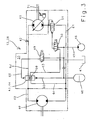
- FIG. 3 shows the motor-pump unit 28 in a schematic detail.
- the hydraulic motor 40 and the hydraulic pump 41 are connected via a line system 42, in which the inventive, designed as a continuous valve 43 switching valve assembly 44 is integrated.
- the motor-pump unit 28 is also integrated in a hydraulic circuit 45, which comprises a known manner as a so-called pressure source running hydraulic pump 46, a tank 47 for storing the hydraulic medium and a pressure accumulator 48.
- the hydraulic circuit 45 operates because of the existing external pressure source 46 as a so-called constant pressure circuit.
- the further electrohydraulic switching valves 49-51 integrated in the hydraulic circuit 45 and the mode of operation of the hydraulic circuit 45 are described in greater detail in connection with the simplified sectional illustration of the switching valve arrangement 44 according to the invention shown in FIG.
- the hydraulic circuit 45 In order for the hydraulic circuit 45 according to the invention to permit an abrupt stop of the intake elements designed as intake and pre-compression rollers 10, at least the hydraulic motor 40, the hydraulic pump 41 and the required switching valves 43, 49-51 are combined in a drive block 33 forming the drive 13, wherein the individual elements 40, 41, 43, 49-51 of the hydraulic circuit 45 are flanged directly to each other and / or interconnected by piping systems. In addition, the switching valves 43, 49-51 of the hydraulic circuit 45 become switched electrohydraulically.
- Such an embodiment has the particular advantage that at least in the area of the hydraulic circuit 45 that realizes the braking of the drive 13 there are neither hose lines nor spring-based valve controls whose elastic properties, such as the pressure-dependent stretching of hose lines and the inertia of spring-based systems, are abrupt Braking the drive 13 of the intake and pre-compression rollers 10 would oppose.
- the continuous valve 43 has terminal housing sections 52, 53 which are penetrated by bores 54 in which control cylinders 55, 56 are displaceably arranged, the movement of the control cylinders 55, 56 being limited by end stops 57.
- At their end faces facing each other take the control cylinder 55, 56 between them a piston surface 58 on the displacement of the control cylinder 55, 56 at the same time to a displacement of the valve piston 59 within the continuous valve 43 leads.
- the "normal operation” the control cylinders 55, 56 are acted upon in their rear regions independently of one another by control pressure lines 60 with a defined control pressure which keeps the valve piston 58 in an equilibrium position according to FIG.
- the operating state "normal operation” is maintained until a foreign body 19 is detected at the foreign body locating device 21 and the rapid stop signal Y is generated in the evaluation and control unit 22 and in the operating state "Quick stop” is switched.
- the rapid stop signal Y leads to the switching of the Stetigventil 43 associated Schnellstoppschaltventils 49 in the position shown in Figure 3.
- the upper control cylinder 56 is depressurized by the hydraulic medium via the pressure line 60 and the associated Schnellstoppschaltventil 49 is discharged into the tank 47.
- the upper control cylinder 56 acts as an opening cylinder.
- the further pressurized lower control cylinder 55 operates in the operating state "quick stop" as a lock cylinder and moves the valve piston 59 in the direction of arrow 65 by the continuous valve 43 according to the invention.
- the piston surface 58 of the valve piston 59 associated front region of the lower control cylinder 55 takes a by bypass bores 66 interspersed by-pass piston 66 on.
- the movement of the lower control cylinder 55 moves the bypass piston 66 in a first step into the region of the pressure line leading to the hydraulic motor 40.
- the hydraulic medium flows bypassing the hydraulic motor 40 via a bypass line 64 back to the hydraulic pump 41, so that the supply of the hydraulic motor 40 with collapses pressurized hydraulic fluid, thus the hydraulic motor 40 is turned off.
- the further movement of the valve piston 59 according to arrow direction 65 closes in a further step by means of an integrally formed on the Vontilkolben 59 aperture 68 the Spülölkanal 63, so that no more hydraulic medium can be dissipated via this.
- the further movement of the valve piston 59 according to arrow 65 leads to the sudden braking of the hydraulic motor 40 and thus to a standstill of the intake and pre-compression rollers 10 by the valve piston 59, the return line 62 from the hydraulic motor 40 to the hydraulic pump 41 closes.
- the hydraulic pump 41 further promotes hydraulic fluid to the hydraulic motor 40, but this can no longer flow, builds up in the pressure line 61 to the hydraulic motor 40 abruptly a back pressure, which stops the hydraulic motor 40 and coupled with him feed and pre-compression rollers 10 abruptly. So that the build-up dynamic pressure does not lead to an overload of the organs acted upon by him, which is acting as opening cylinder control cylinder 56 associated end of the valve piston 59 of Drvsselschlitzen 69 passes through the excess hydraulic fluid from the engine return 62 can flow.
- the throttle slots 69, the control cylinder 55, 56th and the valve piston 59 dimensioned so that adjusts a back pressure, which is in the range of the operating pressure of the hydraulic circuit 25 and preferably 350 bar.
- the movement of the lock cylinder 55 according to arrow direction 65 also leads to a continuous reduction of the passage cross section of the throttle slots 69.
- the differential surface of the valve piston 59 is dimensioned so that the valve piston 59 is then in equilibrium with the pressurized lock cylinder 55 when the back pressure reaches a defined value, has reached 350 bar in the illustrated embodiment. This ensures the safe holding of the brake function in a simple manner.
- the valve piston 59 of the continuous valve 43 is assigned a check valve 70 in the form of a sealing disk 73 which can be moved by the hydraulic medium.
- the sealing disk 73 is arranged in a freely movable manner between the piston surface of the valve piston 59 contacted by the jam cylinders 55, 56 and an adjusting ring 74 fitted in the valve piston 59 and is pressed against the adjusting ring 74 or the valve piston 59 depending on the direction of flow of the hydraulic medium.
- the check valve 70 In the operating state "normal operation", the check valve 70 is closed because the hydraulic medium flowing back from the hydraulic motor 40 to the hydraulic pump 41 via the return line 62 pressurizes the sealing disk 73 in the direction of the piston surface of the valve piston 59 and thus in the closing direction.
- the hydraulic pump 46 operating as a pressure source conveys a pressure oil flow in the opening direction of the check valve 70, in which the sealing washer 73 rests against the adjusting ring 74, so that during the operating mode "rapid stop” the control oil flow generated by the hydraulic pump 46 into the hydraulic circuit 45 of the invention arrives, so that in this also during the braking process, the so-called feed pressure is maintained.
- the hydraulic pump 41 may also be assigned a designed as an electrohydraulic switching valve brake valve 51 which decelerates the coupled via an external drive 71 to the hydraulic pump 41 Humbleseltrommel 16 after switching off its drive.
- This has the effect, in particular, that long follow-up times of the shut-off cutterhead 16 avoided.
- the triggering of the braking function can be achieved, for example, that the pressure source switching valve 50 switches the brake valve 51 by means of a control pressure in the blocking position, so that the rotational movement of the hydraulic pump 41 blocks and thus the chopper drum 16 is suddenly decelerated to a standstill.
- control cylinder 56 designed as an opening cylinder is assigned a throttle cross-section 72 at the top, via which the hydraulic medium displaced by the control cylinder 56 is discharged.
- the control cylinder 56 is braked before it reaches the stop 57 assigned to it and reaches the stop 57 with little impact.
Abstract
Description
Die Erfindung betrifft eine landwirtschaftliche Arbeitsmaschine mit mittels eines Hydraulikkreislaufes hydraulisch angetriebenen Einzugsorganen nach dem Oberbegriff des Anspruchs 1.The invention relates to an agricultural machine with hydraulically driven by a hydraulic circuit intake members according to the preamble of
Ein derartiges System ist unter anderem aus der
Das Problem der geringen verfügbaren Reaktionszeit wird im Stand der Technik, wie etwa in der
Es ist deshalb Aufgabe der Erfindung, die beschriebenen Nachteile des Standes der Technik zu vermeiden und insbesondere einen schnellen Stopp der Einzugsorgane im Falle der Aufnahme von Fremdkörpern mit niedrigem Bauteil- und Bauraumaufwand zu ermöglichen.It is therefore an object of the invention to avoid the disadvantages of the prior art described and in particular to allow a quick stop of the intake organs in the case of receiving foreign bodies with low component and space requirements.
Diese Aufgabe wird erfindungsgemäß durch die kennzeichnenden Merkmale des Anspruchs 1 gelöst.This object is achieved by the characterizing features of
Indem die erfindungsgemäße Schaltventilanordnung zumindest eine Bremsfunktion für den wenigstens einen Hydromotor umfasst und der die Bremsfunktion realisierende Abschnitt des Hydraulikkreislaufs im wesentlichen frei von Elastizitäten ist, wird sichergestellt, dass bei Detektion von Fremdkörpern im Emtegutstrang ein abruptes Anhalten der Einzugs- und Vorpresswalzen möglich wird, da elastizitätsbedingte Trägheiten nicht überwunden werden müssen.By the switching valve arrangement according to the invention comprises at least one brake function for the at least one hydraulic motor and the brake function realizing portion of the hydraulic circuit is substantially free of elasticities, it is ensured that upon detection of foreign bodies in Emtegutstrang an abrupt halting of the intake and pre-compression rollers is possible because elasticity-induced inertia need not be overcome.
Eine kompakte, wenig Bauteile umfassende Ausgestaltung des erfindungsgemäßen Hydraulikkreislaufs ergibt sich dann, wenn die Schaltventilanordnung in einem Betriebszustand "Normalbetrieb" und wenigstens einem Betriebszustand "Schnellstopp" betreibbar ist.A compact design of the hydraulic circuit according to the invention which has few components is obtained when the switching valve arrangement can be operated in an operating state "normal operation" and at least one operating state "rapid stop".
In einer einfachen konstruktiven Ausgestaltung ermöglicht die Schaltventilanordnung in dem Betriebszustand "Normalbetrieb" eine Druckbeaufschlagung des Motors und das Spülen des Hydraulikmediums.In a simple structural design, the switching valve arrangement in the operating state "normal operation" allows pressurization of the engine and flushing of the hydraulic medium.
Eine besonders vorteilhafte Ausgestaltung der Erfindung ergibt sich dann, wenn die Schaltventilanordnung in dem Betriebszustand "Schnellstopp" einen Arbeitszyklus durchläuft, in dem in einem ersten Schritt die Förderung des Hydraulikmediums zum Hydromotor zumindest teilweise unterbrochen wird, in einem weiteren Schritt das Spülen des Hydraulikmediums eingestellt wird und in wenigstens einem dritten Schritt das Abbremsen des Hydromotors erfolgt. Auf diese Weise ermöglicht eine einzige Ventilanordnung die Abarbeitung des gesamten Betriebszustandes "Schnellstopp".A particularly advantageous embodiment of the invention results when the switching valve arrangement in the operating state "rapid stop" passes through a working cycle in which in a first step, the promotion of the hydraulic medium to the hydraulic motor is at least partially interrupted, in a further step, the purging of the hydraulic medium is adjusted and in at least a third step, the deceleration of the hydraulic motor takes place. In this way, a single valve arrangement allows the execution of the entire operating state "rapid stop".
Eine konstruktiv einfache, kompakte und wirkungsvolle Umsetzung des Betriebszustandes "Schnellstopp" ergibt sich dann, wenn die Schaltventilanordnung als Stetigventil ausgebildet ist, dessen Ventilkolben durch Ansteuerung von zumindest zwei Steuerzylindem in seiner Bewegung steuerbar ist.A structurally simple, compact and effective implementation of the operating state "rapid stop" results when the switching valve arrangement is designed as a continuous valve, the valve piston is controlled by controlling at least two Steuerzylindem in its movement.
Um eine hohe Flexibilität in der Steuerbarkeit der Schnellstoppfunktion zu erhalten ist es von Vorteil, wenn in einer Ausgestaltung der Erfindung die Steuerzylinder unabhängig voneinander ansteuerbar sind.In order to obtain a high flexibility in the controllability of the quick stop function, it is advantageous if in one embodiment of the invention, the control cylinders are independently controllable.
In einer vorteilhaften Weiterbildung der Erfindung umfasst der die Schritte des Arbeitszyklus im Betriebszustand "Schnellstopp" realisierende Ventilkolben eine Kolbenfläche, die von den Zylinderflächen der wenigstens zwei Steuerzylinder an gegenüberliegenden Seiten kontaktiert wird. Auf diese Weise kann der Ventilkolben zuverlässig und auf konstruktiv einfache Weise von den Steuerzylindern geführt werden.In an advantageous development of the invention, the valve piston which realizes the steps of the work cycle in the operating state "rapid stop" comprises a piston surface which is contacted by the cylindrical surfaces of the at least two control cylinders on opposite sides. In this way, the valve piston can be guided reliably and in a structurally simple manner by the control cylinders.
Eine effiziente und schnell arbeitende Umsteuerung zwischen den Betriebzuständen ergibt sich dann, wenn der eine Steuerzylinder als Schließzylinder ausgeführt ist und permanent durch einen Steuerdruck druckbeaufschlagt wird und der weitere Steuerzylinder als Öffnungszylinder ausgeführt ist und der Steuerdruck mit dem der weitere Steuerzylinder druckbeaufschlagbar ist zu- oder abgeschaltet werden kann.An efficient and fast-acting reversal between the operating conditions results when the one control cylinder is designed as a lock cylinder and is permanently pressurized by a control pressure and the other Control cylinder is designed as an opening cylinder and the control pressure with which the other control cylinder can be pressurized is switched on or off.
In vorteilhafter Weiterbildung der Erfindung wird durch die Abschaltung des Steuerdrucks des weiteren Steuerzylinders das Umschalten der Schaltventilanordnung von dem Betriebszustand "Normalbetrieb" in den Betriebszustand "Schnellstopp" bewirkt.In an advantageous embodiment of the invention, the switching off of the switching valve arrangement of the operating state "normal operation" in the operating state "rapid stop" is effected by switching off the control pressure of the other control cylinder.
Damit nach Abschaltung des Hauptantriebes die Nachlaufzeit von umlaufenden Arbeitsorganen, wie etwa der Häckseltrommel reduzierte werden kann ist dem Hydraulikkreislauf in einer vorteilhaften Ausgestaltung der Erfindung ein Bremsventil in der Weise zugeordnet ist, dass die Drehbewegung der Hydropumpe und der mit ihr in Wirkverbindung stehenden Arbeitsorgane abgebremst wird.Thus, after switching off the main drive, the follow-up time of rotating work organs, such as the chopper drum can be reduced, the hydraulic circuit in an advantageous embodiment of the invention, a brake valve is assigned in such a way that the rotational movement of the hydraulic pump and standing in operative connection with them working bodies is decelerated ,
Wegen der erforderlichen extrem niedrigen Reaktionszeiten zwischen dem Erkennen eines Fremdkörpers und dem Auslösen der Schnellstoppfunktion ist in an sich bekannter Weise der Fremdkörper-Ortungsvorrichtung eine Auswert- und Steuereinheit zugeordnet, die in Abhängigkeit von einem Ortungssignal X der Fremdkörper-Ortungsvorrichtung ein Schnellstoppsignal Y zur Umschaltung der Schaltventilanordnung in den Betriebszustand "Schnellstopp" generiertBecause of the required extremely low response times between the recognition of a foreign body and the triggering of the quick stop function of the foreign body locating device an evaluation and control unit is assigned in a conventional manner, in response to a locating signal X of the foreign body locating device rapid stop signal Y for switching Switching valve assembly in the operating state "rapid stop" generated
Damit ein sicheres Arbeiten des erfindungsgemäßen Hydraulikkreislaufs in dem Betriebszustand "Normalbetrieb" und ein extrem schnelles Abbremsen des Antriebs während des Bremsvorganges im Betriebszustand "Schnellstopp" gewährleistet werden, verharren in vorteilhafter Ausgestaltung der Erfindung die wenigstens zwei Steuerzylinder der Schaltventilanordnung im Betriebszustand "Normalbetrieb" und zumindest teilweise während der Abarbeitung des dritten Schritts des Arbeitszyklus der Schaltventilanordnung in dem Betriebszustand "Schnellstopp" im Gleichgewicht.To ensure safe operation of the hydraulic circuit according to the invention in the operating state "normal operation" and extremely fast braking of the drive during the braking operation in the operating state "quick stop" remain in an advantageous embodiment of the invention, the at least two control cylinders of the switching valve assembly in the operating state "normal operation" and at least partially during the execution of the third step of the duty cycle of the switching valve assembly in the operating state "rapid stop" in equilibrium.
Auf konstruktiv einfache Weise kann der Gleichgewichtszustand zwischen den Steuerzylindem im Betriebszustand "Normalbetrieb" dadurch erreicht werden, dass die Zylinderflächenverhältnisse der Steuerzylinder aufeinander abgestimmt sind und/oder die Druckbeaufschlagung der Steuerzylinder mit gesteuerten Drücken des Hydraulikmediums erfolgt.In a structurally simple manner, the equilibrium state between the Steuerzylindem in the operating state "normal operation" can be achieved in that the cylinder surface ratios of the control cylinder are matched and / or the pressurization of the control cylinder with controlled pressures of the hydraulic medium takes place.
Ein sicheres Halten des Gleichgewichtszustandes im Betriebszustand "Schnellstopp" wird in vorteilhafter Ausgestaltung der Erfindung dann erreicht, wenn im wesentlichen am Ende des dritten Schrittes des Arbeitszyklus, die resultierende Druckkraft des druckbeaufschlagten Steuerzylinders im Gleichgewicht mit der von der Differenzfläche des Ventilkolbens und einem auf den Ventilkolben wirkenden Staudruck abhängigen Reaktionskraft steht.A secure hold of the equilibrium state in the operating state "rapid stop" is achieved in an advantageous embodiment of the invention, if substantially at the end of the third step of the working cycle, the resulting pressure force of the pressurized control cylinder in equilibrium with that of the differential surface of the valve piston and one on the valve piston acting dynamic pressure dependent reaction force is.
Auf konstruktiv einfache Weise wird der erste Schritt des Arbeitszyklus des erfindungsgemäßen Stetigventils dadurch realisiert, dass dem Schließzylinder ein Bypasskolben zugeordnet ist dessen zumindest eine Bypassbohrung während der Bewegung des Ventilkolbens im ersten Schritt des Arbeitszyklusses eine Bypassleitung öffnet über die zumindest ein Teil des zum Hydromotor fließenden Hydraulikmediums abgeleitet wird.In a structurally simple manner, the first step of the duty cycle of the continuous valve according to the invention is realized in that the lock cylinder is associated with a bypass piston whose at least one bypass hole during the movement of the valve piston in the first step of the work cycle opens a bypass line on the at least a portion of the hydraulic fluid flowing to the hydraulic medium is derived.
Damit das in dem erfindungsgemäßen Hydraulikkreislauf verfügbare Hydraulikmedium nahezu vollständig zur Realisierung eines abrupten Abbremsens im Betriebszustand "Schnellstopp" herangezogen werden kann, der Hydraulikkreislauf also stets über den erforderlichen Speisedruck verfügt, kann in vorteilhafter Ausgestaltung der Erfindung der Bypassleitung ein Rückschlagventil in der Weise zugeordnet sein, dass die Druckquelle den Hydraulikkreislauf während des Schnellstoppvorganges mit Hydraulikmedium versorgen kann, während im Normalbetrieb das Rückschlagventil geschlossen ist.In order that the hydraulic medium available in the hydraulic circuit according to the invention can be almost completely used for realizing an abrupt deceleration in the operating state "rapid stop", ie the hydraulic circuit always has the required feed pressure, the bypass line can be assigned a check valve in an advantageous embodiment of the invention. that the pressure source can supply the hydraulic circuit with hydraulic medium during the rapid stop process, while in normal operation the check valve is closed.
In vorteilhafter Ausgestaltung der Erfindung weist der Ventilkolben eine Blende auf, die während der Bewegung des Ventilkolbens im zweiten Schritt des Arbeitszyklusses die Verbindung zwischen dem Arbeitsanschluss und einem Spülölkanal unterbricht. Dies hat insbesondere den Vorteil, dass vor dem Abbremsen des Antriebs sichergestellt wird, dass das gesamte im Hydraulikkreislauf verfügbare Hydraulikmedium zur Realisierung der Bremsfunktion verfügbar ist.In an advantageous embodiment of the invention, the valve piston on a diaphragm which interrupts the connection between the working port and a Spülölkanal during the movement of the valve piston in the second step of the working cycle. This has the particular advantage that it is ensured before braking the drive that the entire hydraulic medium available in the hydraulic circuit for the realization of the brake function is available.
Damit das gesamte im Hydraulikkreislauf verfügbare Hydraulikmedium schlagartig zur Realisierung der Bremsfunktion verfügbar ist, weist der Ventilkolben einenends Drosselschlitze auf, die während der Bewegung des Ventilkolbens im dritten Schritt des Arbeitszyklusses die Rücklaufleitung vom Hydromotor zur Hydropumpe schließen, wobei das von der Hydropumpe nachgeförderte Hydraulikmedium einen Staudruck zum Abbremsen des Hydromotors aufbaut, der vorzugsweise im Bereich des zulässigen Betriebsdruckes liegt.So that the entire hydraulic medium available in the hydraulic circuit is abruptly available for the realization of the brake function, the valve piston on one choke slots which close during the movement of the valve piston in the third step of the work cycle, the return line from the hydraulic motor to the hydraulic pump, wherein the nachgeförderte of the hydraulic pump hydraulic fluid back pressure builds up for braking the hydraulic motor, which is preferably in the range of the permissible operating pressure.
Damit Druckspitzen und extreme Beschleunigungen in dem erfindungsgemäßen Hydraulikkreislauf weitgehend vermieden werden und somit der belastungsabhängige Verschleiß niedrig gehalten wird, sind in vorteilhafter Weiterbildung der Erfindung dem Ventilkolben eine Vielzahl von Drosselstellen in der Weise zugeordnet sind, dass sich in Abhängigkeit von dem von dem Ventilkolben zurückgelegten Kolbenweg der freie Durchgangsquerschnitt für das Hydraulikmedium stetig ändert.Thus, pressure peaks and extreme accelerations in the hydraulic circuit according to the invention are largely avoided and thus the load-dependent wear is kept low, are in an advantageous embodiment of the invention, the valve piston a plurality of throttle bodies are assigned in such a way that depending on the piston piston travel from the piston the free passage cross section for the hydraulic medium changes continuously.
Damit die Steuerzylinder in ihren Endbereichen nicht ungebremst mit hoher Geschwindigkeit auf die jeweiligen Anschläge auftreffen sind in einer weiteren vorteilhaften Ausgestaltung der Erfindung den zumindest zwei Steuerzylindern Steuerkanten und/oder Drosselstellen in der Weise zugeordnet sind, dass die Bewegung des Ventilkolbens in den Endbereichen abgebremst wird.So that the control cylinders do not impinge unopposed at high speed on the respective stops are in a further advantageous embodiment of the invention the at least two control cylinders control edges and / or throttle points are assigned in such a way that the movement of the valve piston is braked in the end regions.
Damit der erfindungsgemäße Antrieb eine kompakte, bauraumsparende Form aufweist und zugleich frei von Elastizitäten, wie etwa langen Schlauchleitungen sein kann, sind in vorteilhafter Weiterbildung der Erfindung der Hydromotor, die Hydropumpe, die Schaltventilanordnung und die zur Ansteuerung des Hydromotors, der Hydropumpe und der Schalfirentilanordnung in den Betriebzuständen "Normalbetrieb" und "Schnellstopp" notwenigen Schaltventile in einem den Antrieb der Einzugsorgane bildenden Antriebsblock zusammengefasst sind.Thus, the drive according to the invention has a compact, space-saving form and at the same time may be free of elasticities, such as long hose lines are in an advantageous embodiment of the invention, the hydraulic motor, the hydraulic pump, the switching valve assembly and for controlling the hydraulic motor, the hydraulic pump and the Schalfirentilanordnung in the operating states "normal operation" and "quick stop" necessary switching valves are combined in a drive unit forming the drive train drive block.
Eine hohe Flexibilität in der Gestaltung des Antriebes im Normal-, Schnellstopp- und Reversierbetrieb für die Einzugs- und Vorpresswalzen sowie das den Einzugs- und Vorpresswalzen vorgeschaltete Querförderorgan des Vorsatzgerätes wird dann erreicht, wenn die Einzugsorgane mit zumindest einem mechanischen Verteilgetriebe gekoppelt sind, dessen Eingangswelle mit dem hydraulischen Antrieb (13) gekoppelt ist und wobei das mechanische Verteilgetriebe zudem über einen weiteren Getriebeausgang verfügt und der weitere Getriebeausgang mit dem Querförderorgan des Vorsatzgerätes gekoppelt ist.A high flexibility in the design of the drive in normal, quick stop and Reversierbetrieb for the intake and pre-compression rollers and the feed and pre-compression rollers upstream cross-conveying the attachment then becomes achieved when the intake members are coupled to at least one mechanical distribution gear, the input shaft to the hydraulic drive (13) is coupled and wherein the mechanical transmission also has a further transmission output and the other transmission output is coupled to the cross conveyor of the attachment.
Weitere vorteilhafte Ausgestaltungen sind Gegenstand weiterer Unteransprüche und werden nachfolgend an Hand eines in mehreren Figuren dargestellten Ausführungsbeispiels beschrieben. Es zeigen:
Figur 1- eine landwirtschaftliche Arbeitsmaschine mit erfindungsgemäßem Antrieb in deiner schematischen Seitenansicht
Figur 2- eine Detaildarstellung des erfindungsgemäßen Antriebs nach
Figur 1 - Figur 3
- eine schematische Darstellung des den erfindungsgemäßen Antrieb bildenden Hydraulikkreislaufs
- Figur 4
- eine Detailschnittdarstellung der erfindungsgemäßen Ventilanordnung
- FIG. 1
- an agricultural machine with inventive drive in your schematic side view
- FIG. 2
- a detailed representation of the drive according to the invention of Figure 1
- FIG. 3
- a schematic representation of the drive according to the invention forming the hydraulic circuit
- FIG. 4
- a detail sectional view of the valve assembly according to the invention
Figur 1 zeigt eine als selbstfahrender Feldhäcksler 2 ausgeführte landwirtschaftliche Arbeitsmaschine 1, der in ihrem frontseitigen Bereich ein als sogenannte Pick-up 4 ausgeführtes Vorsatzgerät 3 zugeordnet ist. Das Vorsatzgerät 3 nimmt im dargestellten Ausführungsbeispiel einen auf dem Boden 5 liegenden Emtegutstrang 6 mittels einer Aufsammeleinrichtung 7 auf, verdichtet diesen mittels einer Niederhalteranordnung 8 und führt den Erntegutstrang 6 schließlich über ein Querförderorgan 9 dem Vorsatzgerät 3 nachgeordneten Einzugs- und Vvrpresswalzen 10 zu. Die Einzugs- und Vorpresswalzen 10 werden paarweise von einem Einzugsgehäuse 11 aufgenommen. In an sich bekannter Weise werden die paarweise angeordneten Einzugs- und Vorpresswalzen 10 aktiv gemäß der Pfeilrichtung 12 mittels eines noch näher zu beschreibenden Antriebs 13 angetrieben. Dabei tritt der verdichtete Erntegutstrang 6 im rückwärtigen Bereich des Einzugsgehäuses 11 oberhalb einer Gegenschneide 14 in den Wirkbereich der Häckselmesser 15 einer aktiv angetriebenen, umlaufenden Häckseltrommel 16 ein. Der zerkleinerte Erntegutstrang 6 tritt schließlich mit hoher Geschwindigkeit im rückwärtigen Bereich der Häckseltrommel aus dieser in einen aufsteigenden Auswurfschacht 17 ein, in dem der Erntegutstrang 6 unter Umständen mittels eines sogenannten Nachbeschleunigers 18 aus dem Feldhäcksler 2 heraus auf ein nicht dargestelltes Ladefahrzeug gefördert wird.Figure 1 shows an executed as a self-propelled
Zur weitgehenden Vermeidung, dass in dem Emtegutstrang 6 eingelagerte Fremdkörper 19 in den Bereich der Häckseltrommel 16 gelangen können, ist dem frontseitigen Einzugswalzenpaar 20 eine an sich bekannte Fremdkörperortungsvorrichtung 21 zugeordnet. Wird der in dem Emtegutstrang 6 eingelagerte Fremdkörper 19 in den Bereich der Fremdkörperortungsvorrichtung 21 gefördert, generiert diese ein Ortungssignal X welches einer Auswert- und Steuereinheit 22 zugeführt wird und in dieser ein sogenanntes Schnellstoppsignal Y generiert, welches den noch näher zu beschreibenden Antrieb 13 der Einzugs- und Vorpresswalzen 10 abschaltet. Nach Beendigung des Schnellstoppvorganges kann der Betreiber 23 der landwirtschaftlichen Arbeitsmaschine 1 über ein Eingabeterminal 24 ein Reversiersignal Z in der Auswert- und Steuereinheit 22 auslösen, welches einen Reversierlauf des Antriebs 13 und der mit ihm gekoppelten Einzugs- und Vorpresswalzen 10 auslöst. Dabei wird der detektierte Fremdkörper 19 wieder aus dem Bereich der Einzugs- und Vorpresswalzen 10 herausgefördert und kann schließlich von dem Betreiber 23 aus dem Erntegutstrang 6 entfemt werden. Es liegt im Rahmen der Erfindung, dass der beschriebene Reversiervorgang auch automatisch nach dem Stillstand der Einzugs- und Vorpresswalzen 10 ausgelöst werden kann.In order to avoid as far as possible that
Je nach Trägheit des Antriebs 13 und der mit ihm gekoppelten Organe vergeht eine gewisse Zeit bis die Einzugs- und Vorpresswalzen 10 nach Aktivierung der Schnellstoppfunktion stillstehen. Diese Zeitspanne darf nicht so groß sein, dass der detektierte Fremdkörper 19 dennoch in den Bereich der umlaufenden Häckseltrommel 16 gelangt. Hier setzt nun die nachfolgen im Detail beschriebene Erfindung an.Depending on the inertia of the
Gemäß Figur 2 überträgt ein erstes Antriebsriemensystem 25 die Antriebsenergie des Motors 26 unter anderem auf die Häckseltrommel 16, von der aus ein weiteres Riemensystem 27 eine hydraulische Motor-Pumpe-Einheit 28 antreibt, die schließlich den stufenlosen hydraulischen Antrieb 13 der Einzugs- und Vorpresswalzen 10 bildet. Hierfür ist der Abtriebswelle 29 der Motor-Pumpe-Einheit 28 über eine Gelenkwelle 30 ein mechanisches Verteilgetriebe 31 zugeordnet, welches zunächst jede der Einzugs- und Vorpresswalzen 10 in an sich bekannter Weise antreibt. Zudem verfügt das Verteilgetriebe 31 über einen weiteren Getriebeausgang 32, der unmittelbar das den Einzugs- und Vorpresswalzen 12 vorgeordnete Querförderorgan 9 des Vorsatzgerätes 3 antreibt. Dies hat insbesondere den Vorteil, dass nunmehr auch das Querförderorgan 9 des Vorsatzgerätes 3 in die noch näher zu beschreibende Schnellstoppfunktion sowie den Reversiervorgang der Einzugs- und Vorpresswalzen 10 eingebunden werden kann. In an sich bekannter Weise werden die übrigen aktiv angetriebenen Organe 7, 8 des jeweiligen Vorsatzgerätes 3 über einen weiteren nicht dargestellten mechanischen Antrieb angetrieben.According to FIG. 2, a first
Figur 3 zeigt die Motor-Pumpe-Einheit 28 in einer schematischen Detaildarstellung. Der Hydromotor 40 und die Hydropumpe 41 sind über ein Leitungssystem 42, in welches die erfindungsgemäße, als Stetigventil 43 ausgebildete Schaltventilanordnung 44 integriert ist miteinander verbunden. Die Motor-Pumpe-Einheit 28 ist zudem in einen Hydraulikkreislauf 45 eingebunden, der in an sich bekannter Weise eine als sogenannte Druckquelle ausgeführte Hydraulikpumpe 46, einen Tank 47 zur Speicherung des Hydraulikmediums und einen Druckspeicher 48 umfasst. In an sich bekannter Weise arbeitet der Hydraulikkreislauf 45 wegen der vorhandenen externen Druckquelle 46 als sogenannter Konstantdruckkreislauf. Die weiteren in den Hydraulikkreislauf 45 integrierten elektrohydraulischen Schaltventile 49-51 und die Arbeitsweise des Hydraulikkreislaufs 45 werden im Zusammenhang mit der in Figur 4 abgebildeten, vereinfachten Schnittdarstellung der erfindungsgemäßen Schaltventilanordnung 44 näher beschrieben. Damit der erfindungsgemäße Hydraulikkreislauf 45 ein abruptes Anhalten der als Einzugs- und Vorpresswalzen 10 ausgeführten Einzugsorgane ermöglichen kann, sind zumindest der Hydromotor 40, die Hydropumpe 41 und die erforderlichen Schaltventile 43, 49-51 in einem den Antrieb 13 bildenden Antriebsblock 33 zusammengefasst, wobei die einzelnen Elemente 40, 41, 43, 49-51 des Hydraulikkreislaufs 45 unmittelbar aneinandergeflanscht und/oder durch Rohrleitungssysteme miteinander verbunden sind. Zudem werden die Schaltventile 43, 49-51 des Hydraulikkreislaufs 45 elektrohydraulisch geschaltet. Eine derartige Ausführung hat insbesondere den Vorteil, dass zumindest in dem das Abbremsen des Antriebs 13 realisierenden Bereich des Hydraulikkreislaufs 45 weder Schlauchleitungen noch federkraftbasierte Ventilsteuerungen vorhanden sind, deren elastische Eigenschaften, wie etwa das druckabhängige Dehnen von Schlauchleitungen und die Trägheit von federkraftbasierten Systemen, einem abrupten Abbremsen des Antriebes 13 der Einzugs- und Vorpresswalzen 10 entgegenstehen würden.FIG. 3 shows the motor-pump unit 28 in a schematic detail. The
Das erfindungsgemäße Stetigventil 43 verfügt gemäß Figur 4 über endseitige Gehäuseabschnitte 52, 53 die von Bohrungen 54 durchsetzt werden in welchen Steuerzylinder 55, 56 verschiebbar angeordnet sind, wobei die Bewegung der Steuerzylinder 55, 56 durch endseitige Anschläge 57 begrenzt wird. An ihren einander zugewandten Stimseiten nehmen die Steuerzylinder 55, 56 zwischen sich eine Kolbenfläche 58 auf über die eine Verschiebung der Steuerzylinder 55, 56 zugleich zu einer Verschiebung des Ventilkolbens 59 innerhalb des Stetigventils 43 führt. In einem ersten Betriebszustand, dem "Normalbetrieb", werden die Steuerzylinder 55, 56 in ihren rückwärtigen Bereichen über Steuerdruckleitungen 60 unabhängig voneinander mit einem definierten Steuerdruck beaufschlagt, der den Ventilkolben 58 in einer Gleichgewichtslage nach Fig. 4 hält. In dieser Gleichgewichtslage ist der Umlauf des Hydraulikmediums zwischen Hydromotor 40 und Hydropumpe 41 geschlossen. Das Hydraulikmedium wird über eine Druckleitung 61 zum Hydromotor 40 und über eine Rücklaufleitung 62 zurückgefördert und von der Hydropumpe 41 erneut zum Hydromotor 40 gefördert. Zugleich wird eine Teilmenge des Hydraulikmediums über einen Spülölkanal 63 aus dem Kreislauf zwecks Kühlung und/oder Filterung entnommen. Es liegt im Rahmen der Erfindung, dass das Gleichgewicht zwischen den Steuerzylindern 55, 56 einerseits durch aufeinander abgestimmte Zylinderflächenverhältnisse oder durch Druckbeaufschlagung der Steuerzylinder 55, 56 mit gesteuerten Öldrücken realisiert werden kann.According to FIG. 4, the continuous valve 43 according to the invention has
Der Betriebszustand "Normalbetrieb" wird solange beibehalten, bis an der Fremdkörperortungsvorrichtung 21 ein Fremdkörper 19 detektiert und in der Auswert-und Steuereinheit 22 das Schnellstoppsignal Y generiert und in den Betriebszustand "Schnellstopp" umgeschaltet wird. Das Schnellstoppsignal Y führt dabei zum Umschalten des dem Stetigventil 43 zugeordneten Schnellstoppschaltventils 49 in die in Figur 3 dargestellte Position. In dieser Position ist der obere Steuerzylinder 56 drucklos geschaltet, indem das Hydraulikmedium über die Druckleitung 60 und das dieser zugeordnete Schnellstoppschaltventil 49 in den Tank 47 abgeführt wird. Im Betriebszustand "Schnellstopp" fungiert der obere Steuerzylinder 56 als Öffnungszylinder. Der weiter druckbeaufschlagte untere Steuerzylinder 55 arbeitet im Betriebszustand "Schnellstopp" als Schließzylinder und bewegt den Ventilkolben 59 gemäß Pfeilrichtung 65 durch das erfindungsgemäße Stetigventil 43. In seinem der Kolbenfläche 58 des Ventilkolbens 59 zugeordneten vorderen Bereich nimmt der untere Steuerzylinder 55 einen von Bypassbohrungen 66 durchsetzte Bypasskolben 66 auf. Die Bewegung des unteren Steuerzylinders 55 verfährt den Bypasskolben 66 in einem ersten Schritt in den Bereich der zum Hydromotor 40 führenden Druckleitung 61. Dabei fließt das Hydraulikmedium unter Umgehung des Hydromotors 40 über eine Bypassleitung 64 zurück zur Hydropumpe 41, sodass die Versorgung des Hydromotors 40 mit unter Druck stehendem Hydraulikmedium zusammenbricht, mithin der Hydromotor 40 abgeschaltet wird. Die weitere Bewegung des Ventilkolbens 59 gemäß Pfeilrichtung 65 schließt in einem weiteren Schritt mittels einer an dem Vontilkolben 59 angeformten Blende 68 den Spülölkanal 63, sodass über diesen kein Hydraulikmedium mehr abgeführt werden kann. Nachdem der Spülölkanal 63 vollständig geschlossen ist führt die weitere Bewegung des Ventilkolbens 59 gemäß Pfeilrichtung 65 zum schlagartigen Abbremsen des Hydromotors 40 und damit zum Stillstand der Einzugs- und Vorpresswalzen 10 indem der Ventilkolben 59 die Rücklaufleitung 62 vom Hydromotor 40 zur Hydropumpe 41 schließt. Da die Hydropumpe 41 weiter Hydraulikmedium zum Hydromotor 40 fördert, dieses aber nicht mehr abfließen kann, baut sich in der Druckleitung 61 zum Hydromotor 40 abrupt ein Staudruck auf, der den Hydromotor 40 und die mit ihm gekoppelten Einzugs- und Vorpresswalzen 10 schlagartig anhält. Damit der sich aufbauende Staudruck nicht zu einer Überlastung der von ihm beaufschlagten Organe führt, ist das dem als Öffnungszylinder fungierenden Steuerzylinder 56 zugeordnete Ende des Ventilkolbens 59 von Drvsselschlitzen 69 durchsetzt, über die überschüssiges Hydraulikmedium aus dem Motorrücklauf 62 abfließen kann. Optimalerweise sind die Drosselschlitze 69, die Steuerzylinder 55, 56 und der Ventilkolben 59 so dimensioniert, dass sich ein Staudruck einstellt, der im Bereich des Betriebsdruckes des Hydraulikkreislaufs 25 liegt und vorzugsweise 350 bar beträgt. Die Bewegung des Schließzylinders 55 gemäß Pfeilrichtung 65 führt zudem zu einer kontinuierlichen Verkleinerung des Durchgangsquerschnitts der Drosselschlitze 69. Die Differenzfläche des Ventilkolbens 59 ist so dimensioniert, dass der Ventilkolben 59 mit dem druckbeaufschlagten Schließzylinder 55 dann im Gleichgewicht steht, wenn der Staudruck einen definierten Wert, im dargestellten Ausführungsbeispiel 350 bar erreicht hat. Damit wird auf einfache Weise das sichere Halten der Bremsfunktion gewährleistet.The operating state "normal operation" is maintained until a
In einer vorteilhaften Weiterbildung der Erfindung ist dem Ventilkolben 59 des erfindungsgemäßen Stetigventils 43 ein Rückschlagventil 70 in Form einer von dem Hydraulikmedium bewegbaren Dichtscheibe 73 zugeordnet. Die Dichtscheibe 73 ist zwischen der von den Stauerzylindern 55, 56 kontaktierten Kolbenfläche des Ventilkolbens 59 und einem in den Ventilkolben 59 eingepassten Stellring 74 freibeweglich angeordnet und wird je nach Fließrichtung des Hydraulikmediums gegen den Stellring 74 oder den Ventilkolben 59 gepresst. Im Betriebszustand "Normalbetrieb" ist das Rückschlagventil 70 geschlossen, da das von dem Hydromotor 40 zur Hydropumpe 41 über die Rücklaufleitung 62 zurückströmende Hydraulikmedium die Dichtscheibe 73 in Richtung der Kolbenfläche des Ventilkolbens 59 und damit in Schließrichtung druckbeaufschlagt. Im Betriebsmodus "Schnellstopp" fördert die als Druckquelle arbeitende Hydropumpe 46 einen Druckölstrom in Öffnungsrichtung des Rückschlagventils 70, in welcher die Dichtscheibe 73 an dem Stellring 74 anliegt, sodass während des Betriebsmodus "Schnellstopp" der durch die Hydropumpe 46 erzeugte Steuerölstrom in den erfindungsgemäßen Hydraulikkreislauf 45 gelangt, damit in diesem auch während des Bremsvorganges der sogenannte Speisedruck aufrechterhalten bleibt.In an advantageous development of the invention, the
In einer weiteren vorteilhaften Ausgestaltung der Erfindung kann der Hydropumpe 41 zudem ein als elektrohydraulisches Schaltventil ausgeführtes Bremsventil 51 zugeordnet sein, welches die über einen externen Antrieb 71 mit der Hydropumpe 41 gekoppelte Häckseltrommel 16 nach Abschaltung ihres Antriebes abbremst. Dies hat vor allem den Effekt, dass lange Nachlaufzeiten der abgeschalteten Häckseltrommel 16 vermieden werden. Das Auslösen der Bremsfunktion kann beispielsweise dadurch erreicht werden, dass das Druckquellenschaltventil 50 das Bremsventil 51 mittels eines Steuerdrucks in die Sperrstellung schaltet, sodass die Drehbewegung der Hydropumpe 41 blockiert und damit die Häckseltrommel 16 schlagartig bis zum Stillstand abgebremst wird.In a further advantageous embodiment of the invention, the
In einer weiteren vorteilhaften Ausgestaltung ist dem als Öffnungszylinder ausgeführten Steuerzylinder 56 obenseitig ein Drosselquerschnitt 72 zugeordnet, über den das von dem Steuerzylinder 56 verdrängte Hydraulikmedium abgeleitet wird. Dies führt dazu, dass der Steuerzylinder 56 vor dem Erreichen des ihm zugeordneten Anschlags 57 abgebremst wird und stoßarm zur Anlage an dem Anschlag 57 gelangt.In a further advantageous embodiment, the
- 11
- landwirtschaftliche Arbeitsmaschineagricultural working machine
- 22
- FeldhäckslerForage
- 33
- Vorsatzgerätheader
- 44
- Pick-upPick up
- 55
- Bodenground
- 66
- ErntegutstrangErntegutstrang
- 77
- Aufsammeleinrichtungpick-up device
- 88th
- NiederhalteranordnungDown assembly
- 99
- QuerförderorganCross conveyor member
- 1010
- Einzugs- und VorpresswalzenFeed and pre-press rolls
- 1111
- Einzugsgehäusefeeder housing
- 1212
- Pfeilrichtungarrow
- 1313
- Antriebdrive
- 1414
- Gegenschneideagainst cutting
- 1515
- Häckselmesserchopping blades
- 1616
- Häckseltrommelcutterhead
- 1717
- Auswurfschachtchute
- 1818
- Nachbeschleunigerpost-accelerator
- 1919
- Fremdkörperforeign body
- 2020
- EinzugswalzenpaarFeed roller pair
- 2121
- FremdkörperortungsvorrichtungForeign body locator
- 2222
- Auswert- und SteuereinheitEvaluation and control unit
- 2323
- Betreiberoperator
- 2424
- Eingabeterminalinput terminal
- 2525
- erstes Antriebsriemensystemfirst drive belt system
- 2626
- Motorengine
- 2727
- weiteres Antriebssystemanother drive system
- 2828
- Motor-Pumpe-EinheitMotor-pump unit
- 2929
- Abtriebswelleoutput shaft
- 3030
- Gelenkwellepropeller shaft
- 3131
- Verteilgetriebedistribution gear
- 3232
- Getriebeausgangtransmission output
- 3333
- Antriebsblockdrive block
- 4040
- Hydromotorhydraulic motor
- 4141
- Hydropumpehydraulic pump
- 4242
- Leitungssystemline system
- 4343
- Stetigventilcontinuous valve
- 4444
- SchaltventilanordnungSwitching valve arrangement
- 4545
- HydraulikkreislaufHydraulic circuit
- 4646
- Hydraulikpumpehydraulic pump
- 4747
- Tanktank
- 4848
- Druckspeicheraccumulator
- 4949
- SchnellstoppschaltventilQuick stop off valve
- 5050
- DruckquellenschaltventilPressure source selector valve
- 5151
- Bremsventilbrake valve
- 52, 5352, 53
- Gehäuseabschnitthousing section
- 5454
- Bohrungdrilling
- 55,5655.56
- Steuerzylindercontrol cylinder
- 5757
- Anschlagattack
- 5858
- Kolbenflächepiston area
- 5959
- Ventilkolbenplunger
- 6060
- Druckleitungpressure line
- 6161
- Druckleitungpressure line
- 6262
- RücklaufleitungReturn line
- 6363
- Spül6lkanalSpül6lkanal
- 6464
- Bypassleitungbypass line
- 6565
- Pfeilrichtungarrow
- 6666
- Bypassbohrungbypass bore
- 6767
- Bypasskolbenbypass piston
- 6868
- Blendecover
- 6969
- Drosselschlitzethrottle slots
- 7070
- Rückschlagventilcheck valve
- 7171
- extemer Antriebexternal drive
- 7272
- DrosselquerschnittThrottle cross section
- 7373
- Dichtscheibesealing washer
- 7474
- Stellringcollar
- XX
- Ortungssignallocating signal
- YY
- SchnellstoppsignalQuick stop signal
- ZZ
- Reversiersignalreversing signal
Claims (26)
dadurch gekennzeichnet,
dass die Schaltventilanordnung (44) zumindest eine Bremsfunktion für den wenigstens einen Hydromotor (40) umfasst und der die Bremsfunktion realisierende Abschnitt des Hydraulikkreislaufs (45) im wesentlichen frei von Elastizitäten ist.Agricultural machine with hydraulically driven by a hydraulic circuit intake members, the retraction members are driven by at least one hydraulic motor and the hydraulic circuit is associated with at least one switching valve arrangement for interrupting or releasing a hydraulic oil flow to the at least one hydraulic motor, which in response to the signal of a foreign body locating device hydraulic oil flow interrupts or releases to the hydraulic motor,
characterized,
in that the switching valve arrangement (44) comprises at least one braking function for the at least one hydraulic motor (40) and the portion of the hydraulic circuit (45) which realizes the braking function is essentially free of elasticities.
dadurch gekennzeichnet,
dass die Schaltventilanordnung (44) in einem Betriebszustand "Normalbetrieb" und wenigstens einem Betriebszustand "Schnellstopp" betreibbar ist.Agricultural machine with hydraulically driven by a hydraulic circuit intake members according to claim 1,
characterized,
in that the switching valve arrangement (44) can be operated in an operating state "normal operation" and at least one operating state "rapid stop".
dadurch gekennzeichnet,
dass die Schaltventilanordnung (44) in dem Betriebszustand "Normalbetrieb" eine Druckbeaufschlagung des Hydromotors (40) und das Spülen des Hydraulikmediums realisiert.Agricultural machine with hydraulically driven by a hydraulic circuit intake organs according to claim 2,
characterized,
that the switching valve arrangement (44) in the operating mode "Normal operation" realizes a pressurization of the hydraulic motor (40) and purging of the hydraulic medium.
dadurch gekennzeichnet,
dass die Schaltventilanordnung (44) in dem Betriebszustand "Schnellstopp" einen Arbeitszyklus durchläuft, in dem in einem ersten Schritt die Förderung des Hydraulikmediums zum Hydromotor (40) zumindest teilweise unterbrochen wird, in einem weiteren Schritt das Spülen des Hydraulikmediums eingestellt wird und in wenigstens einem dritten Schritt das Abbremsen des Hydromotors (40) erfolgt.Agricultural machine with hydraulically driven by a hydraulic circuit intake organs according to claim 2,
characterized,
that the switching valve assembly (44) in the operating state "rapid stop" passes through a duty cycle, in which in a first step, the promotion of Hydraulic medium to the hydraulic motor (40) is at least partially interrupted, in a further step, the purging of the hydraulic medium is adjusted and in at least a third step, the deceleration of the hydraulic motor (40).
dadurch gekennzeichnet,
dass die Schaltventilanordnung (44) als Stetigventil (43) ausgebildet ist, dessen Ventilkolben (59) durch Ansteuerung von zumindest zwei Steuerzylindern (55, 56) in seiner Bewegung steuerbar ist.Agricultural machine with hydraulically driven by a hydraulic circuit intake organs according to one of the preceding claims,
characterized,
in that the switching valve arrangement (44) is designed as a continuous valve (43) whose valve piston (59) can be controlled in its movement by controlling at least two control cylinders (55, 56).
dadurch gekennzeichnet,
dass die Steuerzylinder (55, 56) unabhängig voneinander ansteuerbar sind.Agricultural machine with hydraulically driven by a hydraulic circuit intake members according to claim 5,
characterized,
that the control cylinder (55, 56) are controllable independently of each other.
dadurch gekennzeichnet,
dass die Zylinderflächen der Steuerzylinder (55, 56) jeweils gegenüberliegenden Kolbenflächen (58) des Ventilkolbens (59) zugeordnet sind.Agricultural machine with hydraulically driven by a hydraulic circuit intake organs according to one of the preceding claims,
characterized,
that the cylinder surfaces of the control cylinders (55, 56) respectively opposite piston surfaces (58) of the valve piston are associated (59).
dadurch gekennzeichnet,
dass der eine Steuerzylinder (55) als Schließzylinder (55) ausgeführt ist und permanent durch einen Steuerdruck druckbeaufschlagt wird.Agricultural machine with hydraulically driven by a hydraulic circuit intake organs according to one of the preceding claims,
characterized,
that the one control cylinder (55) is designed as a lock cylinder (55) and is permanently pressurized by a control pressure.
dadurch gekennzeichnet,
dass der weitere Steuerzylinder (56) als Öffnungszylinder (56) ausgeführt ist und der Steuerdruck mit dem der weitere Steuerzylinder (56) druckbeaufschlagbar ist zu- oder abgeschaltet werden kann.Agricultural machine with hydraulically driven by a hydraulic circuit intake organs according to one of the preceding claims,
characterized,
that the further control cylinder (56) is designed as an opening cylinder (56) and can be switched on or off the control pressure with which the further control cylinder (56) can be pressurized.
dadurch gekennzeichnet,
dass die Abschaltung des Steuerdrucks des weiteren Steuerzylinders (56) das Umschalten der Schaltventilanordnung (44) von dem Betriebszustand "Normalbetrieb" in den Betriebszustand "Schnellstopp" bewirkt.Agricultural machine with hydraulically driven by a hydraulic circuit intake organs according to claim 9,
characterized,
that the switch-off of the control pressure of the further control cylinder (56) causes the switching of the switching valve assembly (44) of the operating state of "normal operation" in the operating state "quick stop".
dadurch gekennzeichnet,
dass dem Hydraulikkreislauf (25) ein Bremsventil (51) in der Weise zugeordnet ist, dass die Drehbewegung der Hydropumpe (41) abgebremst werden kann.Agricultural machine with hydraulically driven by a hydraulic circuit intake organs according to one of the preceding claims,
characterized,
in that a brake valve (51) is assigned to the hydraulic circuit (25) in such a way that the rotational movement of the hydraulic pump (41) can be braked.
dadurch gekennzeichnet,
dass der Fremdkörperortungsvorrichtung (21) eine Auswert- und Steuereinheit (22) zugeordnet ist, die in Abhängigkeit von einem Ortungssignal X der Fremdkörperortungsvorrichtung (21) ein Schnellstoppsignal Y zur Umschaltung der Schaltventilanordnung (44) in den Betriebszustand "Schnellstopp" generiert.Agricultural machine with hydraulically driven by a hydraulic circuit intake organs according to one of the preceding claims,
characterized,
in that the foreign body location device (21) is assigned an evaluation and control unit (22) which generates a rapid stop signal Y for switching the switching valve arrangement (44) into the "rapid stop" operating state as a function of a locating signal X of the foreign body locating device (21).
dadurch gekennzeichnet,
dass die wenigstens zwei Steuerzylinder (55, 56) der Schaltventilanordnung (44) im Betriebszustand "Normalbetrieb" und zumindest teilweise während der Abarbeitung des dritten Schritts des Arbeitszyklus der Schaltventilanordnung (44) in dem Betriebszustand "Schnellstopp" im Gleichgewicht verharren.Agricultural machine with hydraulically driven by means of a hydraulic circuit intake organs according to one of the preceding Claims,
characterized,
in that the at least two control cylinders (55, 56) of the switching valve arrangement (44) remain in equilibrium in the operating state "normal operation" and at least partially during the execution of the third step of the working cycle of the switching valve arrangement (44) in the "rapid stop" operating state.
dadurch gekennzeichnet,
dass der Gleichgewichtszustand im Betriebszustand "Normalbetrieb" durch aufeinander abgestimmte Zylinderflächenverhältnisse der Steuerzylinder (55, 56) und/oder durch Druckbeaufschlagung der Steuerzylinder (55, 56) mit gesteuerten Drücken des Hydraulikmediums realisiert wird.Agricultural machine with hydraulically driven by a hydraulic circuit intake members according to claim 13,
characterized,
that the equilibrium state in the operating state "normal operation" is realized by coordinated cylinder surface ratios of the control cylinders (55, 56) and / or by pressurization of the control cylinders (55, 56) with controlled pressures of the hydraulic medium.
dadurch gekennzeichnet,
dass das Gleichgewicht der Steuerzylinder (55, 56) im Betriebszustand "Schnellstopp" im wesentlichen am Ende des dritten Schrittes des Arbeitszyklus dadurch erreicht wird, dass die resultierende Druckkraft des druckbeaufschlagten Steuerzylinders (55) im Gleichgewicht mit der von der Differenzfläche des Ventilkolbens (59) und einem auf den Ventilkolben (59) wirkenden Staudruck abhängigen Reaktionskraft steht.Agricultural machine with hydraulically driven by a hydraulic circuit intake members according to claim 13,
characterized,
that the balance of the control cylinders (55, 56) in the operating state "rapid stop" substantially at the end of the third step of the working cycle is achieved in that the resulting pressure force of the pressurized control cylinder (55) in equilibrium with that of the differential surface of the valve piston (59) and a reaction pressure acting on the valve piston (59) dependent reaction force.
dadurch gekennzeichnet,
dass dem Schließzylinder (55) ein Bypasskolben (67) zugeordnet ist dessen zumindest eine Bypassbohrung (66) während der Bewegung des Ventilkolbens (59) im ersten Schritt des Arbeitszyklusses eine Bypassleitung (64) öffnet über die zumindest ein Teil des zum Hydromotor (40) fließenden Hydraulikmediums abgeleitet wird.Agricultural machine with hydraulically driven by a hydraulic circuit intake organs according to one of the preceding claims,
characterized,
that associated with a bypass piston (67) the lock cylinder (55) which is at least one bypass bore (66) during movement of the valve piston (59) opens a bypass line (64) of the operating cycle in the first step on at least a part of the hydraulic motor (40) flowing hydraulic medium is derived.
dadurch gekennzeichnet,
dass dem Bypass ein Rückschlagventil (70) zum Schließen des Bypasses zugeordnet ist.Agricultural machine with hydraulically driven by a hydraulic circuit intake members according to claim 16,
characterized,
that the bypass is associated with a check valve (70) for closing the bypass.
dadurch gekennzeichnet,
dass der Ventilkolben (59) eine Blende (68) aufweist, die während der Bewegung des Ventilkolbens (59) im zweiten Schritt des Arbeitszyklusses die Verbindung zwischen dem Arbeitsanschluss und einem Spülölkanal (63) unterbricht.Agricultural machine with hydraulically driven by a hydraulic circuit intake organs according to one of the preceding claims,
characterized,
in that the valve piston (59) has an orifice (68) which interrupts the connection between the working connection and a flushing oil duct (63) during the movement of the valve piston (59) in the second step of the working cycle.
dadurch gekennzeichnet,
dass der Ventilkolben (59) einenends Drosselschlitze (69) aufweist, die während der Bewegung des Ventilkolbens (59) im dritten Schritt des Arbeitszyklusses die Rücklaufleitung (62) vom Hydromotor (40) zur Hydropumpe (41) schließen und wobei das von der Hydropumpe (41) nachgeförderte Hydraulikmedium einen Staudruck zum Abbremsen des Hydromotors (40) aufbaut.Agricultural machine with hydraulically driven by a hydraulic circuit intake organs according to one of the preceding claims,
characterized,
in that the valve piston (59) has one or more throttle slots (69) closing the return line (62) from the hydraulic motor (40) to the hydraulic pump (41) during movement of the valve piston (59) in the third step of the work cycle; 41) nachgeförderte hydraulic fluid builds up a back pressure for braking the hydraulic motor (40).
dadurch gekennzeichnet,
dass der Staudruck den Betriebsdruck im Bereich des zulässigen Betriebsdruckes liegt.Agricultural machine with hydraulically driven by a hydraulic circuit intake members according to claim 19,
characterized,
that the back pressure to the operating pressure is in the range of allowable operating pressure.
dadurch gekennzeichnet,
dass dem Ventilkolben (59) eine Vielzahl von Drosselstellen in der Weise zugeordnet sind, dass sich in Abhängigkeit von dem von dem Ventilkolben (59) zurückgelegten Kolbenweg der freie Durchgangsquerschnitt für das Hydraulikmedium stetig ändert.Agricultural machine with hydraulically driven by a hydraulic circuit intake organs according to one of the preceding claims,
characterized,
in that a large number of throttle points are assigned to the valve piston (59) in such a way that the free passage cross section for the hydraulic medium changes continuously as a function of the piston travel traveled by the valve piston (59).
dadurch gekennzeichnet,
dass den zumindest zwei Steuerzylindern (55, 56) Steuerkanten und/oder Drosselstellen in der Weise zugeordnet sind, dass die Bewegung des Ventilkolbens (59) in den Endbereichen abgebremst wird.Agricultural machine with hydraulically driven by a hydraulic circuit intake organs according to one of the preceding claims,
characterized,
in that the at least two control cylinders (55, 56) are assigned control edges and / or throttle points in such a way that the movement of the valve piston (59) in the end regions is braked.
dadurch gekennzeichnet,
dass der Hydromotor (40), die Hydropumpe (41), die Schaltventilanordnung (44) und die zur Ansteuerung des Hydromotors (40), der Hydropumpe (41) und der Schaltventilanordnung (44) zumindest in den Betriebzuständen "Normalbetrieb" und "Schnellstopp" notwendigen Schaltventile (49-51) in einem den Antrieb (13) der Einzugsorgane (10) bildenden Antriebsblock (33) zusammengefasst sind.Agricultural machine with hydraulically driven by a hydraulic circuit intake organs according to one of the preceding claims,
characterized,
in that the hydraulic motor (40), the hydraulic pump (41), the switching valve arrangement (44) and for the control of the hydraulic motor (40), the hydraulic pump (41) and the switching valve arrangement (44) at least in the operating states "normal operation" and "rapid stop" necessary switching valves (49-51) in a drive (13) of the retraction members (10) forming the drive block (33) are combined.
dadurch gekennzeichnet,
dass die Einzugsorgane (10) mit zumindest einem mechanischen Verteilgetriebe (31) gekoppelt sind, dessen Eingangswelle (30) mit dem hydraulischen Antrieb (13) gekoppelt ist und wobei das mechanische Verteilgetriebe (30) zudem über einen weiteren Getriebeausgang (32) verfügt.Agricultural machine with hydraulically driven by a hydraulic circuit intake organs according to one of the preceding claims,
characterized,
that the feeding members (10) are coupled to at least one mechanical transfer gearbox (31) whose input shaft (30) with the hydraulic drive (13) is coupled and wherein the mechanical distribution gear (30) also has a further transmission output (32).
dadurch gekennzeichnet,
dass der weitere Getriebeausgang (32) mit einem Querförderorgan (9) eines den Einzugsorganen (10) vorgeordneten Vorsatzgerät (3) gekoppelt ist.Agricultural machine with hydraulically driven by a hydraulic circuit intake members according to claim 24,
characterized,
in that the further transmission output (32) is coupled to a transverse conveying member (9) of an attachment (3) arranged upstream of the intake members (10).
dadurch gekennzeichnet,
dass der Antrieb (13) im Reversierbetrieb betrieben werden kann.Agricultural machine with hydraulically driven by a hydraulic circuit intake organs according to one of the preceding claims,
characterized,
may be operated that the drive (13) in the reversing operation.
Applications Claiming Priority (1)
| Application Number | Priority Date | Filing Date | Title |
|---|---|---|---|
| DE102005023047A DE102005023047A1 (en) | 2005-05-13 | 2005-05-13 | Feed mechanism control for agricultural machine |
Publications (2)
| Publication Number | Publication Date |
|---|---|
| EP1721518A1 true EP1721518A1 (en) | 2006-11-15 |
| EP1721518B1 EP1721518B1 (en) | 2009-09-23 |
Family
ID=36586158
Family Applications (1)
| Application Number | Title | Priority Date | Filing Date |
|---|---|---|---|
| EP06004359A Not-in-force EP1721518B1 (en) | 2005-05-13 | 2006-03-03 | Control of a feeding member of an agricultural working machine |
Country Status (4)
| Country | Link |
|---|---|
| US (1) | US7464525B2 (en) |
| EP (1) | EP1721518B1 (en) |
| AT (1) | ATE443436T1 (en) |
| DE (2) | DE102005023047A1 (en) |
Cited By (4)
| Publication number | Priority date | Publication date | Assignee | Title |
|---|---|---|---|---|
| EP2132973A1 (en) | 2008-06-13 | 2009-12-16 | Deere & Company | Drive system for an agricultural harvester |
| WO2010003966A1 (en) * | 2008-07-11 | 2010-01-14 | Deere & Company | Drive system for an infeed conveyor of a harvester |
| EP2145527A2 (en) * | 2008-07-18 | 2010-01-20 | GKN Walterscheid GmbH | Drive assembly for an agricultural work machine |
| DE102012107227A1 (en) | 2012-08-07 | 2014-02-13 | Linde Hydraulics Gmbh & Co. Kg | Drive system for driving e.g. chaff device of chaff-cutter utilized for harvesting crop, has flow pump adjusted based on maximum delivery volume by controller, where chaff device is decelerated by pressure security device of closed circuit |
Families Citing this family (8)
| Publication number | Priority date | Publication date | Assignee | Title |
|---|---|---|---|---|
| DE102007025310A1 (en) * | 2007-05-30 | 2008-12-04 | Claas Selbstfahrende Erntemaschinen Gmbh | Agricultural harvester with a foreign object detection device |
| DE102009035571A1 (en) * | 2009-07-31 | 2011-02-03 | Hydac System Gmbh | Hydrostatic drive |
| GB2479566A (en) * | 2010-04-15 | 2011-10-19 | Agco Int Gmbh | Braking system for a rotating chopper drum of a forage harvester |
| DE102012218546A1 (en) * | 2012-10-11 | 2014-04-17 | Putzmeister Engineering Gmbh | Hydraulic drive system and method for driving a belt conveyor |
| BE1022404B1 (en) * | 2013-12-16 | 2016-03-24 | Cnh Industrial Belgium Nv | CROP COLLECTOR, AGRICULTURAL TOOL AND METHOD FOR EJECTING A STRANGE OBJECT |
| US9915192B2 (en) * | 2014-08-04 | 2018-03-13 | Jeffrey J. Buschur | Power conversion device |
| US9510514B2 (en) * | 2015-04-14 | 2016-12-06 | Deere & Company | Lockout closure mechanism for agricultural vehicle |
| CN106922318A (en) * | 2017-02-17 | 2017-07-07 | 山东省农业机械科学研究院 | Biomass pulverizer |
Citations (6)
| Publication number | Priority date | Publication date | Assignee | Title |
|---|---|---|---|---|
| EP0567851A1 (en) * | 1992-04-30 | 1993-11-03 | Claas Saulgau Gmbh | Drive mechanism for the feed rolls of a forage harvester |
| DE10021663A1 (en) | 2000-05-04 | 2001-11-15 | Krone Bernhard Gmbh Maschf | Self-propelled forage harvester has housing in which more than two pairs of feed rollers are mounted in front of chopper, upper rollers of pairs having common drive which allows their height to be adjusted |
| DE10036612A1 (en) | 2000-07-27 | 2002-02-14 | Case Harvesting Sys Gmbh | Forage harvesters with hydraulically driven feeders |
| US6388860B1 (en) * | 2000-02-17 | 2002-05-14 | Deere & Company | Dual switch control system |
| US20030080305A1 (en) * | 2001-10-26 | 2003-05-01 | Ina-Schaeffler Kg | Electromagnet, in particular a proportional magnet for operating a hydraulic valve |
| US20030172638A1 (en) * | 2000-03-06 | 2003-09-18 | Ameye Danny R | Feeder controls for a forage harvester |
Family Cites Families (7)
| Publication number | Priority date | Publication date | Assignee | Title |
|---|---|---|---|---|
| US3736753A (en) * | 1971-09-22 | 1973-06-05 | Deere & Co | Hydraulic drive |
| JPS63134869A (en) * | 1986-11-25 | 1988-06-07 | Daikin Ind Ltd | Variable capacity type piston machinery |
| JPH02212670A (en) * | 1989-02-10 | 1990-08-23 | Honda Motor Co Ltd | Clutch control device for speed change gear |
| DE19904626C2 (en) * | 1999-02-05 | 2001-05-17 | Case Harvesting Sys Gmbh | Process for the detection of foreign bodies in harvesting machines |
| DE19955901A1 (en) * | 1999-11-20 | 2001-05-23 | Deere & Co | Device for locking a crop transport device |
| JP2001349426A (en) * | 2000-06-05 | 2001-12-21 | Komatsu Ltd | Capacity control device for hydraulic pump, and brake control device of hydraulic motor |
| US7022012B2 (en) * | 2004-09-02 | 2006-04-04 | Cnh America Llc | Sensitivity adjustment for stone detection system |
-
2005
- 2005-05-13 DE DE102005023047A patent/DE102005023047A1/en not_active Withdrawn
-
2006
- 2006-03-03 EP EP06004359A patent/EP1721518B1/en not_active Not-in-force
- 2006-03-03 AT AT06004359T patent/ATE443436T1/en active
- 2006-03-03 DE DE502006004898T patent/DE502006004898D1/en active Active
- 2006-05-09 US US11/430,777 patent/US7464525B2/en not_active Expired - Fee Related
Patent Citations (6)
| Publication number | Priority date | Publication date | Assignee | Title |
|---|---|---|---|---|
| EP0567851A1 (en) * | 1992-04-30 | 1993-11-03 | Claas Saulgau Gmbh | Drive mechanism for the feed rolls of a forage harvester |
| US6388860B1 (en) * | 2000-02-17 | 2002-05-14 | Deere & Company | Dual switch control system |
| US20030172638A1 (en) * | 2000-03-06 | 2003-09-18 | Ameye Danny R | Feeder controls for a forage harvester |
| DE10021663A1 (en) | 2000-05-04 | 2001-11-15 | Krone Bernhard Gmbh Maschf | Self-propelled forage harvester has housing in which more than two pairs of feed rollers are mounted in front of chopper, upper rollers of pairs having common drive which allows their height to be adjusted |
| DE10036612A1 (en) | 2000-07-27 | 2002-02-14 | Case Harvesting Sys Gmbh | Forage harvesters with hydraulically driven feeders |
| US20030080305A1 (en) * | 2001-10-26 | 2003-05-01 | Ina-Schaeffler Kg | Electromagnet, in particular a proportional magnet for operating a hydraulic valve |
Cited By (12)
| Publication number | Priority date | Publication date | Assignee | Title |
|---|---|---|---|---|
| EP2132973A1 (en) | 2008-06-13 | 2009-12-16 | Deere & Company | Drive system for an agricultural harvester |
| DE102008002428A1 (en) | 2008-06-13 | 2009-12-17 | Deere & Company, Moline | Drive system for a harvester |
| EA016881B1 (en) * | 2008-06-13 | 2012-08-30 | Дир Энд Компани | Drive system for an agricultural harvester |
| EA016881B8 (en) * | 2008-06-13 | 2012-10-30 | Дир Энд Компани | Drive system for an agricultural harvester |
| WO2010003966A1 (en) * | 2008-07-11 | 2010-01-14 | Deere & Company | Drive system for an infeed conveyor of a harvester |
| DE102009002849A1 (en) | 2008-07-11 | 2010-01-14 | Deere & Company, Moline | Drive system for a feed conveyor of a harvester |
| EA018822B1 (en) * | 2008-07-11 | 2013-10-30 | Дир Энд Компани | Drive system for an infeed conveyor of a harvester |
| EP2145527A2 (en) * | 2008-07-18 | 2010-01-20 | GKN Walterscheid GmbH | Drive assembly for an agricultural work machine |
| EP2145527A3 (en) * | 2008-07-18 | 2012-06-27 | GKN Walterscheid GmbH | Drive assembly for an agricultural work machine |
| DE102012107227A1 (en) | 2012-08-07 | 2014-02-13 | Linde Hydraulics Gmbh & Co. Kg | Drive system for driving e.g. chaff device of chaff-cutter utilized for harvesting crop, has flow pump adjusted based on maximum delivery volume by controller, where chaff device is decelerated by pressure security device of closed circuit |
| US9398744B2 (en) | 2012-08-07 | 2016-07-26 | Linde Hydraulics Gmbh & Co. Kg | Drive system for driving a chopper and feeder device of a harvesting machine |
| DE102012107227B4 (en) | 2012-08-07 | 2022-07-14 | Linde Hydraulics Gmbh & Co. Kg | Drive system for driving a chopping and intake device of a harvesting machine |
Also Published As
| Publication number | Publication date |
|---|---|
| EP1721518B1 (en) | 2009-09-23 |
| US20060254235A1 (en) | 2006-11-16 |
| ATE443436T1 (en) | 2009-10-15 |
| US7464525B2 (en) | 2008-12-16 |
| DE502006004898D1 (en) | 2009-11-05 |
| DE102005023047A1 (en) | 2007-01-18 |
Similar Documents
| Publication | Publication Date | Title |
|---|---|---|
| EP1721518B1 (en) | Control of a feeding member of an agricultural working machine | |
| DE19934782C2 (en) | Method and arrangement for controlling a hydraulic vehicle drive | |
| EP1828642B1 (en) | Hydrostatic drive with speed limitation | |
| DE102010053105B4 (en) | Hydrostatic drive | |
| DE102014221594B4 (en) | Hydrostatic braking concept | |
| DE112012004874B4 (en) | Hydraulic drive system | |
| EP1588077B1 (en) | Control of a hydrostatic gearbox | |
| EP1932419B1 (en) | Agricultural compactor | |
| WO2009065383A1 (en) | Hydraulic control arrangement and distribution valve section | |
| EP0530842B1 (en) | Reversible hydrostatic transmission with brake valve | |
| DE102014214441B4 (en) | Method and arrangement for decelerating a hydrostatic drive | |
| EP0904468B2 (en) | Rotary mechanism control system with bilateral braking | |
| DE102008000093B4 (en) | Drive system for hydraulic motors for driving the wood loading elements of the delimbing and separating head of a forest harvester | |
| EP1264989A1 (en) | Load relief device for a lifting device | |
| DE10219849B4 (en) | Hydraulic motor unit | |
| EP2860397B1 (en) | Drive system for hydraulically driven working parts of a working machine | |
| WO2013083234A1 (en) | Hydrostatic drive system | |
| DE102012107227B4 (en) | Drive system for driving a chopping and intake device of a harvesting machine | |
| DE4234139C2 (en) | Control device of a hydrostatic transmission with a brake valve | |
| DE3825726C2 (en) | Hydraulic shift arrangement for a vehicle with a hydrostatic transmission | |
| EP1303177B1 (en) | Forage harvester with hydraulically driven collecting members | |
| DE1296024B (en) | Control device for a hydrostatic drive for vehicles | |
| DE4039830C1 (en) | Variable transmission with V-belt - incorporates hydraulic system for controlling setting of conical pulleys | |
| DE102017204461A1 (en) | Hydrostatic drive | |
| EP0456175B1 (en) | Hydrostatic drive system for vehicles |
Legal Events
| Date | Code | Title | Description |
|---|---|---|---|
| PUAI | Public reference made under article 153(3) epc to a published international application that has entered the european phase |
Free format text: ORIGINAL CODE: 0009012 |
|
| AK | Designated contracting states |
Kind code of ref document: A1 Designated state(s): AT BE BG CH CY CZ DE DK EE ES FI FR GB GR HU IE IS IT LI LT LU LV MC NL PL PT RO SE SI SK TR |
|
| AX | Request for extension of the european patent |
Extension state: AL BA HR MK YU |
|
| 17P | Request for examination filed |
Effective date: 20070515 |
|
| 17Q | First examination report despatched |
Effective date: 20070619 |
|
| AKX | Designation fees paid |
Designated state(s): AT BE BG CH CY CZ DE DK EE ES FI FR GB GR HU IE IS IT LI LT LU LV MC NL PL PT RO SE SI SK TR |
|
| GRAP | Despatch of communication of intention to grant a patent |
Free format text: ORIGINAL CODE: EPIDOSNIGR1 |
|
| GRAS | Grant fee paid |
Free format text: ORIGINAL CODE: EPIDOSNIGR3 |
|
| GRAA | (expected) grant |
Free format text: ORIGINAL CODE: 0009210 |
|
| AK | Designated contracting states |
Kind code of ref document: B1 Designated state(s): AT BE BG CH CY CZ DE DK EE ES FI FR GB GR HU IE IS IT LI LT LU LV MC NL PL PT RO SE SI SK TR |
|
| REG | Reference to a national code |
Ref country code: GB Ref legal event code: FG4D Free format text: NOT ENGLISH |
|
| REG | Reference to a national code |
Ref country code: CH Ref legal event code: EP |
|
| REG | Reference to a national code |
Ref country code: IE Ref legal event code: FG4D |
|
| REF | Corresponds to: |
Ref document number: 502006004898 Country of ref document: DE Date of ref document: 20091105 Kind code of ref document: P |
|
| PG25 | Lapsed in a contracting state [announced via postgrant information from national office to epo] |
Ref country code: SE Free format text: LAPSE BECAUSE OF FAILURE TO SUBMIT A TRANSLATION OF THE DESCRIPTION OR TO PAY THE FEE WITHIN THE PRESCRIBED TIME-LIMIT Effective date: 20090923 Ref country code: FI Free format text: LAPSE BECAUSE OF FAILURE TO SUBMIT A TRANSLATION OF THE DESCRIPTION OR TO PAY THE FEE WITHIN THE PRESCRIBED TIME-LIMIT Effective date: 20090923 Ref country code: LT Free format text: LAPSE BECAUSE OF FAILURE TO SUBMIT A TRANSLATION OF THE DESCRIPTION OR TO PAY THE FEE WITHIN THE PRESCRIBED TIME-LIMIT Effective date: 20090923 |
|
| LTIE | Lt: invalidation of european patent or patent extension |
Effective date: 20090923 |
|
| PG25 | Lapsed in a contracting state [announced via postgrant information from national office to epo] |
Ref country code: SI Free format text: LAPSE BECAUSE OF FAILURE TO SUBMIT A TRANSLATION OF THE DESCRIPTION OR TO PAY THE FEE WITHIN THE PRESCRIBED TIME-LIMIT Effective date: 20090923 Ref country code: LV Free format text: LAPSE BECAUSE OF FAILURE TO SUBMIT A TRANSLATION OF THE DESCRIPTION OR TO PAY THE FEE WITHIN THE PRESCRIBED TIME-LIMIT Effective date: 20090923 Ref country code: PL Free format text: LAPSE BECAUSE OF FAILURE TO SUBMIT A TRANSLATION OF THE DESCRIPTION OR TO PAY THE FEE WITHIN THE PRESCRIBED TIME-LIMIT Effective date: 20090923 |
|
| NLV1 | Nl: lapsed or annulled due to failure to fulfill the requirements of art. 29p and 29m of the patents act | ||
| PG25 | Lapsed in a contracting state [announced via postgrant information from national office to epo] |
Ref country code: CY Free format text: LAPSE BECAUSE OF FAILURE TO SUBMIT A TRANSLATION OF THE DESCRIPTION OR TO PAY THE FEE WITHIN THE PRESCRIBED TIME-LIMIT Effective date: 20090923 |
|
| REG | Reference to a national code |
Ref country code: IE Ref legal event code: FD4D |
|
| PG25 | Lapsed in a contracting state [announced via postgrant information from national office to epo] |
Ref country code: PT Free format text: LAPSE BECAUSE OF FAILURE TO SUBMIT A TRANSLATION OF THE DESCRIPTION OR TO PAY THE FEE WITHIN THE PRESCRIBED TIME-LIMIT Effective date: 20100125 Ref country code: ES Free format text: LAPSE BECAUSE OF FAILURE TO SUBMIT A TRANSLATION OF THE DESCRIPTION OR TO PAY THE FEE WITHIN THE PRESCRIBED TIME-LIMIT Effective date: 20100103 Ref country code: CZ Free format text: LAPSE BECAUSE OF FAILURE TO SUBMIT A TRANSLATION OF THE DESCRIPTION OR TO PAY THE FEE WITHIN THE PRESCRIBED TIME-LIMIT Effective date: 20090923 Ref country code: RO Free format text: LAPSE BECAUSE OF FAILURE TO SUBMIT A TRANSLATION OF THE DESCRIPTION OR TO PAY THE FEE WITHIN THE PRESCRIBED TIME-LIMIT Effective date: 20090923 Ref country code: EE Free format text: LAPSE BECAUSE OF FAILURE TO SUBMIT A TRANSLATION OF THE DESCRIPTION OR TO PAY THE FEE WITHIN THE PRESCRIBED TIME-LIMIT Effective date: 20090923 Ref country code: IE Free format text: LAPSE BECAUSE OF FAILURE TO SUBMIT A TRANSLATION OF THE DESCRIPTION OR TO PAY THE FEE WITHIN THE PRESCRIBED TIME-LIMIT Effective date: 20090923 Ref country code: IS Free format text: LAPSE BECAUSE OF FAILURE TO SUBMIT A TRANSLATION OF THE DESCRIPTION OR TO PAY THE FEE WITHIN THE PRESCRIBED TIME-LIMIT Effective date: 20100123 |
|
| PG25 | Lapsed in a contracting state [announced via postgrant information from national office to epo] |
Ref country code: SK Free format text: LAPSE BECAUSE OF FAILURE TO SUBMIT A TRANSLATION OF THE DESCRIPTION OR TO PAY THE FEE WITHIN THE PRESCRIBED TIME-LIMIT Effective date: 20090923 |
|
| PG25 | Lapsed in a contracting state [announced via postgrant information from national office to epo] |
Ref country code: DK Free format text: LAPSE BECAUSE OF FAILURE TO SUBMIT A TRANSLATION OF THE DESCRIPTION OR TO PAY THE FEE WITHIN THE PRESCRIBED TIME-LIMIT Effective date: 20090923 Ref country code: NL Free format text: LAPSE BECAUSE OF FAILURE TO SUBMIT A TRANSLATION OF THE DESCRIPTION OR TO PAY THE FEE WITHIN THE PRESCRIBED TIME-LIMIT Effective date: 20090923 |
|
| PLBE | No opposition filed within time limit |
Free format text: ORIGINAL CODE: 0009261 |
|
| STAA | Information on the status of an ep patent application or granted ep patent |
Free format text: STATUS: NO OPPOSITION FILED WITHIN TIME LIMIT |
|
| 26N | No opposition filed |
Effective date: 20100624 |
|
| PG25 | Lapsed in a contracting state [announced via postgrant information from national office to epo] |
Ref country code: MC Free format text: LAPSE BECAUSE OF NON-PAYMENT OF DUE FEES Effective date: 20100331 Ref country code: GR Free format text: LAPSE BECAUSE OF FAILURE TO SUBMIT A TRANSLATION OF THE DESCRIPTION OR TO PAY THE FEE WITHIN THE PRESCRIBED TIME-LIMIT Effective date: 20091224 |
|
| REG | Reference to a national code |
Ref country code: CH Ref legal event code: PL |
|
| GBPC | Gb: european patent ceased through non-payment of renewal fee |
Effective date: 20100303 |
|
| PG25 | Lapsed in a contracting state [announced via postgrant information from national office to epo] |
Ref country code: CH Free format text: LAPSE BECAUSE OF NON-PAYMENT OF DUE FEES Effective date: 20100331 Ref country code: LI Free format text: LAPSE BECAUSE OF NON-PAYMENT OF DUE FEES Effective date: 20100331 |
|
| PG25 | Lapsed in a contracting state [announced via postgrant information from national office to epo] |
Ref country code: IT Free format text: LAPSE BECAUSE OF FAILURE TO SUBMIT A TRANSLATION OF THE DESCRIPTION OR TO PAY THE FEE WITHIN THE PRESCRIBED TIME-LIMIT Effective date: 20090923 Ref country code: GB Free format text: LAPSE BECAUSE OF NON-PAYMENT OF DUE FEES Effective date: 20100303 |
|
| PG25 | Lapsed in a contracting state [announced via postgrant information from national office to epo] |
Ref country code: HU Free format text: LAPSE BECAUSE OF FAILURE TO SUBMIT A TRANSLATION OF THE DESCRIPTION OR TO PAY THE FEE WITHIN THE PRESCRIBED TIME-LIMIT Effective date: 20100324 Ref country code: BG Free format text: LAPSE BECAUSE OF FAILURE TO SUBMIT A TRANSLATION OF THE DESCRIPTION OR TO PAY THE FEE WITHIN THE PRESCRIBED TIME-LIMIT Effective date: 20090923 Ref country code: LU Free format text: LAPSE BECAUSE OF NON-PAYMENT OF DUE FEES Effective date: 20100303 |
|
| PG25 | Lapsed in a contracting state [announced via postgrant information from national office to epo] |
Ref country code: TR Free format text: LAPSE BECAUSE OF FAILURE TO SUBMIT A TRANSLATION OF THE DESCRIPTION OR TO PAY THE FEE WITHIN THE PRESCRIBED TIME-LIMIT Effective date: 20090923 |
|
| REG | Reference to a national code |
Ref country code: AT Ref legal event code: MM01 Ref document number: 443436 Country of ref document: AT Kind code of ref document: T Effective date: 20110303 |
|
| PG25 | Lapsed in a contracting state [announced via postgrant information from national office to epo] |
Ref country code: AT Free format text: LAPSE BECAUSE OF NON-PAYMENT OF DUE FEES Effective date: 20110303 |
|
| REG | Reference to a national code |
Ref country code: FR Ref legal event code: PLFP Year of fee payment: 11 |
|
| REG | Reference to a national code |
Ref country code: FR Ref legal event code: PLFP Year of fee payment: 12 |
|
| REG | Reference to a national code |
Ref country code: FR Ref legal event code: PLFP Year of fee payment: 13 |
|
| PGFP | Annual fee paid to national office [announced via postgrant information from national office to epo] |
Ref country code: DE Payment date: 20220322 Year of fee payment: 17 |
|
| PGFP | Annual fee paid to national office [announced via postgrant information from national office to epo] |
Ref country code: FR Payment date: 20220321 Year of fee payment: 17 Ref country code: BE Payment date: 20220321 Year of fee payment: 17 |
|
| REG | Reference to a national code |
Ref country code: DE Ref legal event code: R119 Ref document number: 502006004898 Country of ref document: DE |
|
| REG | Reference to a national code |
Ref country code: BE Ref legal event code: MM Effective date: 20230331 |
|
| PG25 | Lapsed in a contracting state [announced via postgrant information from national office to epo] |
Ref country code: FR Free format text: LAPSE BECAUSE OF NON-PAYMENT OF DUE FEES Effective date: 20230331 Ref country code: DE Free format text: LAPSE BECAUSE OF NON-PAYMENT OF DUE FEES Effective date: 20231003 |
|
| PG25 | Lapsed in a contracting state [announced via postgrant information from national office to epo] |
Ref country code: BE Free format text: LAPSE BECAUSE OF NON-PAYMENT OF DUE FEES Effective date: 20230331 |