EP1264989A1 - Load relief device for a lifting device - Google Patents
Load relief device for a lifting device Download PDFInfo
- Publication number
- EP1264989A1 EP1264989A1 EP02011317A EP02011317A EP1264989A1 EP 1264989 A1 EP1264989 A1 EP 1264989A1 EP 02011317 A EP02011317 A EP 02011317A EP 02011317 A EP02011317 A EP 02011317A EP 1264989 A1 EP1264989 A1 EP 1264989A1
- Authority
- EP
- European Patent Office
- Prior art keywords
- pressure
- lifting
- valve
- fluid
- lifting device
- Prior art date
- Legal status (The legal status is an assumption and is not a legal conclusion. Google has not performed a legal analysis and makes no representation as to the accuracy of the status listed.)
- Ceased
Links
Images
Classifications
-
- A—HUMAN NECESSITIES
- A01—AGRICULTURE; FORESTRY; ANIMAL HUSBANDRY; HUNTING; TRAPPING; FISHING
- A01B—SOIL WORKING IN AGRICULTURE OR FORESTRY; PARTS, DETAILS, OR ACCESSORIES OF AGRICULTURAL MACHINES OR IMPLEMENTS, IN GENERAL
- A01B63/00—Lifting or adjusting devices or arrangements for agricultural machines or implements
- A01B63/02—Lifting or adjusting devices or arrangements for agricultural machines or implements for implements mounted on tractors
- A01B63/10—Lifting or adjusting devices or arrangements for agricultural machines or implements for implements mounted on tractors operated by hydraulic or pneumatic means
- A01B63/11—Lifting or adjusting devices or arrangements for agricultural machines or implements for implements mounted on tractors operated by hydraulic or pneumatic means for controlling weight transfer between implements and tractor wheels
-
- F—MECHANICAL ENGINEERING; LIGHTING; HEATING; WEAPONS; BLASTING
- F15—FLUID-PRESSURE ACTUATORS; HYDRAULICS OR PNEUMATICS IN GENERAL
- F15B—SYSTEMS ACTING BY MEANS OF FLUIDS IN GENERAL; FLUID-PRESSURE ACTUATORS, e.g. SERVOMOTORS; DETAILS OF FLUID-PRESSURE SYSTEMS, NOT OTHERWISE PROVIDED FOR
- F15B1/00—Installations or systems with accumulators; Supply reservoir or sump assemblies
- F15B1/02—Installations or systems with accumulators
- F15B1/021—Installations or systems with accumulators used for damping
Definitions
- the invention relates to a relief device for a lifting device with at least a lifting element according to the preamble of claim 1.
- Throttle cross sections are also unsuitable for reducing pressure peaks in a very short time, so that the vibration-dependent Loads on the lifting device and the carrier vehicle can nevertheless be very high can.
- the damping of the oscillating movement a lifting device depending on the position of the lifting device off.
- the pressure accumulator is switched on Damping connected directly to the pressure side of the lifting cylinder, so that occurring Pressure peaks without overcoming a throttle cross-section directly into the pressure accumulator managed and dismantled. Even with such a design, the swinging movement the lifting device is not permanently damped. If the damping is not switched on occurring load peaks are only discharged into the pressure accumulator via a throttle cross-section become. Due to the throttle cross section to be overcome, the damping of load peaks insufficient in this switch position.
- the invention is therefore based on the object of a relief device for a lifting device of the type mentioned at the outset so that the lifting device occurring load peaks can be permanently reduced to the load-dependent Wear of the lifting device and the carrier vehicle receiving the lifting device to reduce.
- the object is achieved by a relief device for a lifting device solved with the characterizing features of claim 1.
- the permanent connection between the pressure storage unit and Lifting device ensures that the pressure in the storage unit can never be lower than that in the line system of the lifting device (s), so that the lifting device drops unintentionally due to a lower pressure in the storage unit to be connected at the moment their connection to the line system of the lifting elements cannot occur.
- the switching valve of the control element according to the invention can be constructed in a structurally simple manner be designed as a 2/2-way valve that the storage unit with the Lifting element connects and interrupts in the locked position, so that the swinging movement is damped the lifting device can either be switched on or off.
- a shutdown could be of particular advantage if this is from the agricultural machine recorded attachment is operated in the so-called auto contour mode and too frequent a reduction in pressure peaks disturb the functioning of the auto contour mode would.
- By switching off the damping it is possible to use a fault-free one Auto contour mode always ensures that high load peaks are independent are still degradable from the operating mode.
- the 2/2 way valve can be controlled in this way be that the medium flowing out of the check valve due to pressure peaks
- the 2/2-way valve can be fed back to the lifting device (s), whereby in the Storage unit restores the original pressure level.
- Control element works throttle-free and the throttle cross section provided for vibration damping in the connecting line between the pressure accumulator and the fluid-operated lifting element is arranged. This can be done in a structurally particularly simple manner when using a Directional control valve can be achieved in that the flow cross-section of the directional control valve as Throttle cross section is formed.
- the switching valve of the invention Control member can also be designed as a pressure relief valve, which in the zero position the at least one pressure accumulator with the pressure chamber of the fluid-operated lifting member connects and interrupts in the switching position, so that the damping of the swinging movement the lifting device can also be optionally switched on or off, wherein in switched off condition is still taken care of to avoid overloading of the pressure accumulator, the pressure relief valve automatically at a certain limit pressure opens.
- the pressure limiting valve can also be controlled his. In the same way as when using controlled directional valves, this enables that the medium flowing through the check valve due to pressure peaks over the pressure relief valve can be fed back to the lifting device (s) and located in the Storage unit restores the original pressure level.
- the check valve of the control element according to the invention operates without throttling during the throttle cross section provided for vibration damping in the connecting line is arranged between the pressure accumulator and the fluid-operated lifting member.
- On constructive This can be done in a particularly simple manner when using a pressure limiting valve can be achieved in that the inlet line to the pressure relief valve has a throttle cross section assigned.
- a particularly flexible adaptation of the pressure of the storage unit to the mean working pressure the lifting device or devices can be achieved when the switching valve of the invention Control element is designed as a proportional valve.
- the storage unit can be advantageously developed of the invention formed by a plurality of individual pressure accumulators connected in parallel become.
- the fluid-operated lifting members of the invention Lifting device can be designed as a hydraulically operated lifting cylinder.
- the relief device according to the invention can be used on such agricultural machines are used, the work organs of fluid-operated Lifting elements can be fixed in different positions in the vertical direction, the working organs depending on the driving speed of the agricultural Machine and the ground contour to be driven over to more or less intense Pitch movements tend.
- the relief device according to the invention in particularly advantageous for the fact that the pitching movement depends on the agricultural Work machine transmitted shock loads can be significantly reduced.
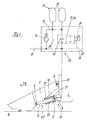
- Figure 1 shows schematically an agricultural machine 1, which on its in the direction of travel FR facing front end an agricultural, not shown Attachment device 2 pivots about an axis 3 pointing transversely to the direction of travel FR.
- Attachment device 2 pivots about an axis 3 pointing transversely to the direction of travel FR.
- the agricultural machine 1 at least one other transverse to the direction of travel FR pointing swivel axis 4 assigned to the frame.
- the at least one further pivot axis In the illustrated embodiment, 4 takes the piston 5 as a single-acting one Lift cylinder 6 executed lifting member 7, the piston rod 8 via a transverse to Axis 9 pointing in the direction of travel FR rotatable with the agricultural attachment 2 connected is.
- the at least one lifting cylinder 6 can be in the area its piston 5 are enclosed by a relief spring 10, the carrier vehicle side is in operative connection with a stop 11 and on the attachment side of the piston 5 encompassing and usually changing its position on the piston 5 stop 12th is limited.
- a supply line 13 connected via which the lifting cylinder 6 can be pressurized or depressurized can.
- the lifting cylinder 6 becomes an energy-transmitting medium via the supply line 12 supplied, the piston rod 8 is pushed out of the piston 5 and that with the Piston rod 8 pivotally connected agricultural attachment 2 pivoted about the arranged on the carrier vehicle 1 pivot axis 3 in the vertical direction upwards.
- the supply line 13 moves the front attachment 2 in a manner known per se, relieved of pressure by gravity the piston rod 8 back into the piston 5 and the attachment 2 now pivots counterclockwise around that arranged on the carrier vehicle 1 Swivel axis 3 back towards the floor 14. While the attachment 2 in the working position 1 is performed directly above the floor 14, it can in the Transport position of the at least one pressurized lifting cylinder 6 in any positions far from the ground are held. Depending on the unevenness of the floor 14 and the driving speed of the carrier vehicle 1, the attachment 2 performs pitching movements from that in the at least one lifting cylinder 6 for short-term pressure increases lead, among other things, as shock loads in the area of the fixed pivot axis 4 be introduced into the carrier vehicle 1.
- Control member 15 is in one 1 embodiment of a check valve 16 and a 2/2-way valve 17 formed, the check valve 16 and the 2/2-way valve 17 in parallel to each other and to which at least one lifting cylinder 6 are arranged.
- Control member 15 and the at least one lifting cylinder 6 via the at least one supply line 13 pressurized and relieved of pressure.
- inlet and outlet line 18 connected connections of the check valve 16 and the not shown 2/2-way valve 17 are in parallel with one another and with one of two via a line system 19 connected individual pressure accumulators 20 connected pressure accumulator unit 21. It is within the scope of the invention that the pressure accumulator unit 21 also has only a single pressure accumulator 20 or a plurality of individual pressure accumulators 20 can be formed.
- the check valve 16 connects the inlet and outlet line 18 to the line system 19 in such a way that the energy transfer medium of the inlet and outlet line 18 is the check valve 16 only in the direction of the line system 19 and thus in the direction of the pressure storage unit 21 and 2/2-way valve 17 can flow through.
- the 2/2-way valve 17 is designed so that it is in a first switch position (Fig. 1), the open position, the line system 19 with the inlet and outlet line 18 and the supply line 13 of the lifting cylinder 6 connects, the energy-transmitting medium in this switching position from the line system 19 and thus from the pressure storage unit 21 and the check valve 16 in the inlet and outlet line 18 and the supply line 13 of the lifting cylinder 6 flows.
- a second switching position the blocking position
- the 2/2-way valve 17 interrupts the connection between the line system 19 and the inlet and outlet line 18 and the supply line 13.
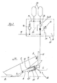
- this can be implemented as a 2/2-way valve 17 executed switching valve 26 can also be designed as a pressure relief valve 27, the Pressure relief valve 27, as shown in Figure 2, also in the open position or in Lock position can be operated to achieve the effects already described. moreover can be assigned to the pressure relief valve 27, a throttle 28, so that the high Pressure and high speed via the check valve 16 in the pressure storage unit 21 discharged oil with lower pressure and delayed, ie damped, the at least one Lift cylinder 6 is closed again.
- the pressure relief valve 27 can also via control lines 29, 30 with the line system 19 of the pressure storage unit 21 and the Supply line 13 and the pressure chamber 33 of the at least one lifting cylinder 6 connected be, so that also a pressure difference dependent opening or closing of the Pressure relief valve 27 can be achieved with the effect that the pressure storage unit 21 is not overloaded and the check valve 16 always against that in the line system 19 of the pressure storage unit 21 applied system pressure for reducing pressure peaks can open.
- the respective switching valve 17, 26, 27 can also be designed as a proportional valve 31 his.
- the lifting device 32 according to the invention has a May have a plurality of lifting members 7, all lifting members 7 at least one according to the invention Relief device 23 have to achieve the effects described.
- the lifting element 7 designed as a single-acting lifting cylinder 6 can also be operated by one or more double-acting, known per se and therefore not shown in detail Lift cylinders are formed.
Landscapes
- Engineering & Computer Science (AREA)
- Life Sciences & Earth Sciences (AREA)
- Mechanical Engineering (AREA)
- Soil Sciences (AREA)
- Environmental Sciences (AREA)
- Physics & Mathematics (AREA)
- Fluid Mechanics (AREA)
- General Engineering & Computer Science (AREA)
- Fluid-Pressure Circuits (AREA)
- Lifting Devices For Agricultural Implements (AREA)
Abstract
Description
Die Erfindung betrifft eine Entlastungsvorrichtung für eine Hubeinrichtung mit zumindest
einem Huborgan gemäß dem Oberbegriff des Anspruchs 1.The invention relates to a relief device for a lifting device with at least
a lifting element according to the preamble of
Derartige Entlastungsvorrichtungen kommen vorrangig dort zum Einsatz, wo die mit der
Hubeinrichtung zu bewegenden Lasten erheblichen Schwingungen unterliegend, die zu einer
hohen Stoßbelastung der Hubeinrichtung und des die Hubeinrichtung aufnehmenden Trägerfahrzeugs
führen können. Aus der deutschen Patentschrift DE 28 56 583 ist eine Entlastungsvorrichtung
für den Dreipunktanbau eines Schleppers bekannt geworden, bei der in Abhängigkeit
von der Fahrgeschwindigkeit eine Dämpfung der Nickbewegung des von der Dreipunktanbauvorrichtung
aufgenommenen Anbaugerätes erfolgt. Der wesentliche Nachteil dieser
Ausführung ist, dass die Dämpfung der Schwingbewegung des Anbaugerätes erst bei höheren
Fahrgeschwindigkeiten erfolgt, wobei die sich schwingbewegungsabhängig im Hydrauliksystem
aufbauenden Druckspitzen über einen Drosselquerschnitt und einen diesem
Drosselquerschnitt nachgeschalteten Druckspeicher abgebaut werden. Drosselquerschnitte
sind zudem ungeeignet, Druckspitzen in sehr kurzer Zeit abzubauen, sodass die schwingungsabhängige
Belastungen der Hubeinrichtung und des Trägerfahrzeugs dennoch sehr hoch sein
kann. In einer Ausführung nach der DE 196 22 762 wird die Dämpfung der Schwingbewegung
einer Hubeinrichtung in Abhängigkeit von der Stellung der Hubvorrichtung zu- oder
abgeschaltet. Um Druckspitzen schnell abbauen zu können, ist der Druckspeicher bei zugeschalteter
Dämpfung direkt mit der Druckseite des Hubzylinders verbunden, sodass auftretende
Druckspitzen ohne Überwindung eines Drosselquerschnitts direkt in den Druckspeicher
geleitet und abgebaut werden. Auch bei einer derartigen Ausführung wird die Schwingbewegung
der Hubeinrichtung nicht permanent gedämpft. Bei nicht zugeschalteter Dämpfung können
auftretende Lastspitzen nur über einen Drosselquerschnitt in den Druckspeicher abgeführt
werden. Aufgrund des zu überwindenden Drosselquerschnitts ist die Dämpfung von Lastspitzen
bei dieser Schaltstellung unzureichend.Such relief devices are primarily used where the with
Lifting device for moving loads subject to considerable vibrations, which lead to a
high shock loading of the lifting device and the carrier vehicle receiving the lifting device
being able to lead. From the
Der Erfindung liegt deshalb die Aufgabe zugrunde, eine Entlastungsvorrichtung für eine Hubeinrichtung der eingangs genannten Art so weiterzuentwickeln, dass an der Hubeinrichtung auftretende Lastspitzen permanent abgebaut werden können, um den belastungsabhängigen Verschleiß der Hubeinrichtung und des die Hubeinrichtung aufnehmenden Trägerfahrzeugs zu reduzieren.The invention is therefore based on the object of a relief device for a lifting device of the type mentioned at the outset so that the lifting device occurring load peaks can be permanently reduced to the load-dependent Wear of the lifting device and the carrier vehicle receiving the lifting device to reduce.
Erfindungsgemäß wird die Aufgabe durch eine Entlastungsvorrichtung für eine Hubeinrichtung
mit den kennzeichnenden Merkmalen des Anspruchs 1 gelöst.According to the invention, the object is achieved by a relief device for a lifting device
solved with the characterizing features of
Indem zwischen der Druckspeichereinheit und dem Huborgan zumindest ein Steuerglied zwischengeschaltet ist, welches von wenigstens einem in Durchlassrichtung das fluidbetätigte Huborgan mit der Druckspeichereinheit verbindenden Rückschlagventil und einem zu diesem Rückschlagventil parallel geschalteten in Durchlassrichtung die Druckspeichereinheit mit dem fluidbetätigten Huborgan verbindenden Schaltventil gebildet wird, ist sichergestellt, dass das wenigstens eine Huborgan der Hubeinrichtung permanent in Wirkverbindung mit dem Druckspeicher steht. Auf diese Weise können schwingungsbedingte Druckspitzen im Leitungssystem der Hubeinrichtung auf konstruktiv einfache Weise in die Druckspeichereinheit abgeführt werden, wobei nach dem Abbau der Druckspitze in der Druckspeichereinheit, dass energieübertragende Medium über das Schaltventil dem Huborgan wieder zugeführt werden kann. Zudem wird durch die permanente Verbindung zwischen Druckspeichereinheit und Huborgan sichergestellt, dass der Druck in der Speichereinheit nie geringer sein kann als der im Leitungssystem des oder der Huborgane, sodass ein ungewolltes Absinken der Hubeinrichtung aufgrund eines niedrigeren Drucks in der zuzuschaltenden Speichereinheit im Moment ihrer Zuschaltung in das Leitungssystem der Huborgane nicht auftreten kann.By interposing at least one control element between the pressure storage unit and the lifting element which of the at least one in the forward direction is the fluid-operated Lifting device with the pressure storage unit connecting check valve and one to this Check valve connected in parallel in the forward direction with the pressure storage unit the switching valve connecting the fluid-operated lifting element is formed, it is ensured that the at least one lifting element of the lifting device permanently in operative connection with the Pressure accumulator is. In this way, vibration-related pressure peaks in the pipe system the lifting device in a structurally simple manner in the pressure storage unit to be dissipated, after the pressure peak has been reduced in the pressure storage unit, that energy-transmitting medium are fed back to the lifting element via the switching valve can. In addition, the permanent connection between the pressure storage unit and Lifting device ensures that the pressure in the storage unit can never be lower than that in the line system of the lifting device (s), so that the lifting device drops unintentionally due to a lower pressure in the storage unit to be connected at the moment their connection to the line system of the lifting elements cannot occur.
Ein nahezu zeitgleicher Abbau von Druckspitzen wird dann erreicht, wenn das Rückschlagventil im Wesentlichen drosselfrei arbeitet. Eine Dämpfung der Schwingbewegung der Hubeinrichtung wird auf konstruktiv einfache Weise dadurch erreicht, dass der Durchfluss des energieübertragenden Mediums von der Druckspeichereinheit zu dem fluidbetätigtem Huborgan über einen Drosselquerschnitt erfolgt.An almost simultaneous reduction of pressure peaks is achieved when the check valve works essentially without throttling. Damping the swinging movement of the lifting device is achieved in a structurally simple manner in that the flow of the energy-transmitting medium from the pressure storage unit to the fluid-operated lifting member over a throttle cross section.
Auf konstruktiv einfache Weise kann das Schaltventil des erfindungsgemäßen Steuergliedes als 2/2-Wegeventil ausgeführt sein, dass in Durchlassstellung die Speichereinheit mit dem Huborgan verbindet und in Sperrstellung unterbricht, sodass die Dämpfung der Schwingbewegung der Hubeinrichtung wahlweise zu- oder abgeschaltet werden kann. Eine Abschaltung könnte vor allem dann von Vorteil sein, wenn das von der landwirtschaftlichen Arbeitsmaschine aufgenommene Vorsatzgerät im sogenannten Autokonturbetrieb betrieben wird und ein zu häufiger Abbau von Druckspitzen die Funktionsweise des Autokonturbetriebes stören würde. Durch das mögliche Abschalten der Dämpfung kann somit neben einem störungsfreien Autokonturbetrieb stets sichergestellt werden, dass hohe Belastungsspitzen unabhängig von der Betriebsart dennoch abbaubar sind.The switching valve of the control element according to the invention can be constructed in a structurally simple manner be designed as a 2/2-way valve that the storage unit with the Lifting element connects and interrupts in the locked position, so that the swinging movement is damped the lifting device can either be switched on or off. A shutdown could be of particular advantage if this is from the agricultural machine recorded attachment is operated in the so-called auto contour mode and too frequent a reduction in pressure peaks disturb the functioning of the auto contour mode would. By switching off the damping, it is possible to use a fault-free one Auto contour mode always ensures that high load peaks are independent are still degradable from the operating mode.
In vorteilhafter Weiterbildung der Erfindung kann das 2/2 Wegeventil in der Weise gesteuert sein, dass das aufgrund von Druckspitzen über das Rückschlagventil abfließende Medium über das 2/2-Wegeventil dem oder den Huborganen wieder zugeführbar ist, wobei sich in der Speichereinheit wieder das ursprüngliche Druckniveau einstellt.In an advantageous development of the invention, the 2/2 way valve can be controlled in this way be that the medium flowing out of the check valve due to pressure peaks The 2/2-way valve can be fed back to the lifting device (s), whereby in the Storage unit restores the original pressure level.
Eine optimale Aufnahme von Druckspitzen bei gleichzeitiger Dämpfung der Nickbewegung der Hubeinrichtung wird dann erreicht, wenn das Rückschlagventil des erfindungsgemäßen Steuergliedes drosselfrei arbeitet und der zur Schwingungsdämpfung vorgesehene Drosselquerschnitt in der Verbindungsleitung zwischen Druckspeicher und fluidbetätigtem Huborgan angeordnet ist. Auf konstruktiv besonders einfache Weise kann dies bei Verwendung eines Wegeventils dadurch erreicht werden, dass der Durchflussquerschnitt des Wegeventils als Drosselquerschnitt ausgebildet ist.Optimal absorption of pressure peaks while dampening the pitching movement the lifting device is reached when the check valve of the invention Control element works throttle-free and the throttle cross section provided for vibration damping in the connecting line between the pressure accumulator and the fluid-operated lifting element is arranged. This can be done in a structurally particularly simple manner when using a Directional control valve can be achieved in that the flow cross-section of the directional control valve as Throttle cross section is formed.
In einer vorteilhaften Weiterbildung der Erfindung kann das Schaltventil des erfindungsgemäßen Steuergliedes auch als Druckbegrenzungsventil ausgebildet sein, welches in der Nullstellung den wenigstens einen Druckspeicher mit dem Druckraum des fluidbetätigten Huborgans verbindet und in der Schaltstellung unterbricht, sodass die Dämpfung der Schwingbewegung der Hubeinrichtung ebenfalls wahlweise zu- oder abgeschaltet werden kann, wobei im abgeschalteten Zustand dennoch dafür gesorgt ist, dass zur Vermeidung von Überlastungen des Druckspeichers dass Druckbegrenzungsventil bei einem bestimmten Grenzdruck automatisch öffnet.In an advantageous development of the invention, the switching valve of the invention Control member can also be designed as a pressure relief valve, which in the zero position the at least one pressure accumulator with the pressure chamber of the fluid-operated lifting member connects and interrupts in the switching position, so that the damping of the swinging movement the lifting device can also be optionally switched on or off, wherein in switched off condition is still taken care of to avoid overloading of the pressure accumulator, the pressure relief valve automatically at a certain limit pressure opens.
In vorteilhafter Weiterbildung der Erfindung kann das Druckbegrenzungsventil ebenfalls gesteuert sein. Dies ermöglicht in gleicher Weise wie beim Einsatz von gesteuerten Wegeventilen, dass das aufgrund von Druckspitzen über das Rückschlagventil abfließende Medium über das Druckbegrenzungsventil dem oder den Huborganen wieder zuführbar ist und sich in der Speichereinheit wieder das ursprüngliche Druckniveau einstellt. In an advantageous development of the invention, the pressure limiting valve can also be controlled his. In the same way as when using controlled directional valves, this enables that the medium flowing through the check valve due to pressure peaks over the pressure relief valve can be fed back to the lifting device (s) and located in the Storage unit restores the original pressure level.
Um ebenfalls beim Einsatz von Druckbegrenzungsventilen eine optimale Aufnahme von Druckspitzen bei gleichzeitiger Dämpfung der Nickbewegung der Hubeinrichtung zu gewährleisten, arbeitet das Rückschlagventil des erfindungsgemäßen Steuergliedes drosselfrei während der zur Schwingungsdämpfüng vorgesehene Drosselquerschnitt in der Verbindungsleitung zwischen Druckspeicher und fluidbetätigtem Huborgan angeordnet ist. Auf konstruktiv besonders einfache Weise kann dies bei Verwendung eines Druckbegrenzungsventils dadurch erreicht werden, dass der Zulaufleitung zum Druckbegrenzungsventil ein Drosselquerschnitt zugeordnet ist.In order to ensure optimum absorption of pressure relief valves To ensure pressure peaks while damping the pitching movement of the lifting device, the check valve of the control element according to the invention operates without throttling during the throttle cross section provided for vibration damping in the connecting line is arranged between the pressure accumulator and the fluid-operated lifting member. On constructive This can be done in a particularly simple manner when using a pressure limiting valve can be achieved in that the inlet line to the pressure relief valve has a throttle cross section assigned.
Eine besonders flexible Anpassung des Drucks der Speichereinheit an den mittleren Arbeitsdruck des oder der Huborgane kann dann erreicht werden, wenn das Schaltventil des erfindungsgemäßen Steuergliedes als Proportionalventil ausgeführt ist.A particularly flexible adaptation of the pressure of the storage unit to the mean working pressure the lifting device or devices can be achieved when the switching valve of the invention Control element is designed as a proportional valve.
Um auch bei hohen durch die Speichereinheit aufzunehmenden Druckspitzen eine Überlastung der Speichereinheit zu vermeiden, kann die Speichereinheit in vorteilhafter Weiterbildung der Erfindung von einer Vielzahl parallel geschalteter Einzeldruckspeicher gebildet werden.In order to overload even with high pressure peaks to be absorbed by the storage unit To avoid the storage unit, the storage unit can be advantageously developed of the invention formed by a plurality of individual pressure accumulators connected in parallel become.
In konstruktiv einfachster Weise können die fluidbetätigten Huborgane der erfindungsgemäßen Hubeinrichtung als hydraulisch betätigte Hubzylinder ausgeführt sein.In a structurally simplest manner, the fluid-operated lifting members of the invention Lifting device can be designed as a hydraulically operated lifting cylinder.
In besonders vorteilhafter Weise kann die erfindungsgemäße Entlastungsvorrichtung an solchen landwirtschaftlichen Arbeitsmaschinen eingesetzt werden, deren Arbeitsorgane von fluidbetätigten Huborganen in verschiedenen Positionen in vertikaler Richtung festlegbar sind, wobei die Arbeitsorgane in Abhängigkeit von der Fahrgeschwindigkeit der landwirtschaftlichen Arbeitsmaschine und der zu überfahrenden Bodenkontur zu mehr oder weniger intensiven Nickbewegungen neigen. Hier sorgt die erfindungsgemäße Entlastungsvorrichtung in besonders vorteilhafter Weise dafür, dass die nickbewegungsabhängig auf die landwirtschaftliche Arbeitsmaschine übertragenen Stoßbelastungen erheblich reduziert werden können.In a particularly advantageous manner, the relief device according to the invention can be used on such agricultural machines are used, the work organs of fluid-operated Lifting elements can be fixed in different positions in the vertical direction, the working organs depending on the driving speed of the agricultural Machine and the ground contour to be driven over to more or less intense Pitch movements tend. Here, the relief device according to the invention in particularly advantageous for the fact that the pitching movement depends on the agricultural Work machine transmitted shock loads can be significantly reduced.
Weitere vorteilhafte Ausgestaltungen sind Gegenstand weiterer Unteransprüche und werden nachfolgend anhand von Zeichnungen näher erläutert.Further advantageous embodiments are the subject of further subclaims and are explained in more detail below with reference to drawings.
Es zeigen:
Figur 1- eine erfindungsgemäße Entlastungsvorrichtung für eine Hubeinrichtung mit 2/2-Wegeventil
Figur 2- eine erfindungsgemäße Entlastungsvorrichtung für eine Hubeinrichtung mit Druckbegrenzungsventil
- Figure 1
- a relief device according to the invention for a lifting device with 2/2-way valve
- Figure 2
- a relief device according to the invention for a lifting device with pressure relief valve
Figur 1 zeigt schematisch eine landwirtschaftliche Arbeitsmaschine 1, die an ihrem in Fahrtrichtung
FR weisenden frontseitigen Ende ein nicht näher dargestelltes landwirtschaftliches
Vorsatzgerät 2 um eine quer zur Fahrtrichtung FR weisende Achse 3 schwenkbar aufnimmt.
Unterhalb der das landwirtschaftliche Vorsatzgerät 2 drehbar aufnehmenden Schwenkachse 3
ist der landwirtschaftlichen Arbeitsmaschine 1 wenigstens eine weitere quer zur Fahrtrichtung
FR weisende Schwenkachse 4 gestellfest zugeordnet. Die wenigstens eine weitere Schwenkachse
4 nimmt im dargestellten Ausführungsbeispiel den Kolben 5 eines als einfach wirkender
Hubzylinders 6 ausgeführten Huborgans 7 auf, dessen Kolbenstange 8 über eine quer zur
Fahrtrichtung FR weisende Achse 9 drehbar mit dem landwirtschaftlichen Vorsatzgerät 2
verbunden ist. In an sich bekannter Weise kann der wenigstens eine Hubzylinder 6 im Bereich
seines Kolbens 5 von einer Entlastungsfeder 10 umschlossen werden, die trägerfahrzeugseitig
mit einem Anschlag 11 in Wirkverbindung steht und vorsatzgeräteseitig von einem den Kolben
5 umgreifenden und in der Regel in seiner Lage am Kolben 5 veränderbaren Anschlag 12
begrenzt wird. An den Kolben 5 des Hubzylinders 6 ist einenends eine Versorgungsleitung 13
angeschlossen über die der Hubzylinder 6 druckbeaufschlagt oder druckentlastet werden
kann. Wird dem Hubzylinder 6 über die Versorgungsleitung 12 ein energieübertragendes Medium
zugeführt, wird die Kolbenstange 8 aus dem Kolben 5 herausgeschoben und das mit der
Kolbenstange 8 gelenkig verbundene landwirtschaftliche Vorsatzgerät 2 verschwenkt um die
am Trägerfahrzeug 1 angeordnete Schwenkachse 3 in vertikaler Richtung nach oben. Wird die
Versorgungsleitung 13 in an sich bekannter Weise druckentlastet bewegt das Vorsatzgerät 2
durch Schwerkraftwirkung die Kolbenstange 8 wieder in den Kolben 5 hinein und das Vorsatzgerät
2 schwenkt nun entgegen dem Uhrzeigersinn um die am Trägerfahrzeug 1 angeordnete
Schwenkachse 3 in Richtung Boden 14 zurück. Während das Vorsatzgerät 2 in der Arbeitsstellung
gemäß Figur 1 unmittelbar über dem Boden 14 geführt wird, kann es in der
Transportstellung von dem wenigstens einen druckbeaufschlagten Hubzylinder 6 in beliebigen
bodenfernen Positionen gehalten werden. In Abhängigkeit von der Unebenheit des Bodens
14 und der Fahrgeschwindigkeit des Trägerfahrzeugs 1 führt das Vorsatzgerät 2 Nickbewegungen
aus, die in dem wenigstens einen Hubzylinder 6 zu kurzzeitigen Druckanstiegen
führen, die unter anderem als Stoßbelastungen im Bereich der gestellfesten Schwenkachse 4
in das Trägerfahrzeug 1 eingeleitet werden. Um diese Stoßbelastungen zu reduzieren, ist in
die fluidführende Leitung 13 des wenigstens einen Huborgans 7 ein erfindungsgemäßes und
noch näher zu beschreibendes Steuerglied 15 eingeschaltet. Das Steuerglied 15 wird in einem
ersten Ausführungsbeispiel nach Figur 1 von einem Rückschlagventil 16 und einem 2/2-Wegeventil
17 gebildet, wobei das Rückschlagventil 16 und das 2/2-Wegeventil 17 in Parallelschaltung
zueinander und zu dem wenigstens einen Hubzylinder 6 angeordnet sind. Über eine
in an sich bekannter und deshalb nicht näher dargestellter Weise mit dem Hydraulikkreislauf
des Trägerfahrzeugs 1 verbundene Zu- und Ablaufleitung 18 wird das erfindungsgemäße
Steuerglied 15 und der wenigstens eine Hubzylinder 6 über dessen wenigstens eine Versorgungsleitung
13 druckbeaufschlagt und druckentlastet. Die nicht mit der Zu- und Ablaufleitung
18 verbundenen nicht näher dargestellten Anschlüsse des Rückschlagventils 16 und des
2/2-Wegeventils 17 sind über ein Leitungssystem 19 miteinander und mit einer aus zwei parallel
geschalteten Einzeldruckspeichern 20 bestehenden Druckspeichereinheit 21 verbunden.
Es liegt im Rahmen der Erfindung, dass die Druckspeichereinheit 21 auch von nur einem Einzeldruckspeicher
20 oder einer Vielzahl von Einzeldruckspeichern 20 gebildet werden kann.
Das Rückschlagventil 16 verbindet die Zu- und Ablaufleitung 18 mit dem Leitungssystem 19
in der Weise, dass das energieübertragende Medium der Zu- und Ablaufleitung 18 das Rückschlagventil
16 nur in Richtung des Leitungssystems 19 und damit in Richtung Druckspeichereinheit
21 und 2/2-Wegeventil 17 durchströmen kann. Das 2/2-Wegeventil 17 ist so ausgeführt,
dass es in einer ersten Schaltstellung (Fig. 1), der Durchlassstellung, das Leitungssystem
19 mit der Zu- und Ablaufleitung 18 und der Versorgungsleitung 13 des Hubzylinders
6 verbindet, wobei das energieübertragende Medium in dieser Schaltstellung von dem Leitungssystem
19 und damit von der Druckspeichereinheit 21 und dem Rückschlagventil 16 in
die Zu- und Ablaufleitung 18 und die Versorgungsleitung 13 des Hubzylinders 6 strömt. In
einer zweiten Schaltstellung, der Sperrstellung, unterbricht das 2/2-Wegeventil 17 die Verbindung
zwischen dem Leitungssystem 19 sowie der Zu- und Ablaufleitung 18 und der Versorgungsleitung
13. In der in Figur 1 dargestellten Arbeitsstellung des Vorsatzgerätes 2 kann
es aufgrund von Bodenunebenheiten dazu kommen, dass eine an der Kolbenstange 8 angreifende
Reaktionskraft bestrebt ist die Kolbenstange 8 in den Kolben 5 des Hubzylinders 6 zu
schieben, wobei es zu einem Druckanstieg in der Versorgungsleitung 13 und der Zu- und
Ablaufleitung 18 kommt. Sind die auftretenden Druckspitzen entsprechend groß, öffnet das
Rückschlagventil 16, sodass die im energieübertragenden Medium aufgetretene Druckspitze
über die Druckspeichereinheit 21 abgebaut werden kann. Befindet sich das 2/2-Wegeventil 17
zu diesem Zeitpunkt in Durchlassstellung, kann die Menge des über das Rückschlagventil 16
abgeflossenen energieübertragenden Mediums dem Hubzylinder 6 wieder zugeführt werden,
wobei der Durchlassquerschnitt im 2/2-Wegeventil 17 zur Schwingungsdämpfung als Drosselquerschnitt
22 ausgeführt ist. Die gleiche Funktionsweise wird erzielt, wenn das Vorsatzgerät
2 von dem wenigstens einen Hubzylinder 6 in einer beliebigen bodenfernen Position
gehalten wird und das Vorsatzgerät 2 aufgrund der Fahrgeschwindigkeit des Trägerfahrzeugs
1 mehr oder weniger intensive Nickbewegungen ausführt, die ebenfalls Druckspitzen in der
Versorgungsleitung 13 des Hubzylinders 6 verursachen. Wird das 2/2-Wegeventil 17 in
Sperrstellung betrieben, kann das über das Rückschlagventil 16 abgeführte Medium dem
Hubzylinder 6 nicht wieder zugeführt werden. Dies führt zu einer allmählichen Aufladung der
Druckspeichereinheit 21, sodass das Rückschlagventil 16 gegen einen zunehmenden Druck
im Leitungssystem 19 öffnen muss. Auf diese konstruktiv sehr einfache Weise kann erreicht
werden, dass das erfindungsgemäße Steuerglied 15 seltener und nur hohe Druckspitzen abbaut.
Dies hat vor allem den Vorteil, dass das in der Regel bodenkopierend im sogenannten
Autokonturbetrieb arbeitende landwirtschaftliche Vorsatzgerät 2 nicht bereits bei kleinen Bodenunebenheiten
in der erfindungsgemäßen Entlastungsvorrichtung 23 Schaltvorgängen auslöst,
was zu übermäßiger Erwärmung und erhöhten Energieverlusten in der erfindungsgemäßen
Entlastungsvorrichtung 23 führen würde. Damit die allmähliche Aufladung der Druckspeichereinheit
21 nicht zu deren Überlastung führt oder das Rückschlagventil 16 letztlich
nicht mehr den im Leitungssystem 19 anliegenden Systemdruck überwinden kann, kann das
2/2-Wegeventil 17 als vorgesteuertes 2/2-Wegeventil 17 ausgeführt sein, welches über Steuerleitungen
24, 25 mit dem Leitungssystem 19 der Druckspeichereinrichtung 21 und der Versorgungsleitung
13 des wenigstens einen Hubzylinders 6 verbunden ist. In Abhängigkeit von
der Druckdifferenz in diesen Leitungssystemen 13, 19 kann so auf einfache Weise dafür gesorgt
werden, dass das in Sperrstellung betriebene 2/2-Wegeventil 17 immer dann selbsttätig
in Durchlassstellung umschaltet, wenn der Druck im Leitungssystem 19 der Druckspeichereinheit
21 einen voreinstellbaren Grenzwert überschreitet. Aufgrund der Parallelschaltung
des Rückschlagventils 16 und des 2/2-Wegeventils 17 ist unabhängig von der momentanen
Schaltstellung des 2/2-Wegeventils 17 stets sichergestellt, dass der Druck im Leitungssystem
19 der Druckspeichereinheit 21 nicht niedriger sein kann als der Druck in den Leitungssystemen
13, 18 sowie dem Druckraum 33 des wenigstens einen Hubzylinders 6.Figure 1 shows schematically an
In einer weiteren vorteilhaften Ausgestaltung der Erfindung kann das als 2/2-Wegeventil 17
ausgeführte Schaltventil 26 auch als Druckbegrenzungsventil 27 ausgeführt sein, wobei das
Druckbegrenzungsventil 27, wie in Figur 2 dargestellt, ebenfalls in Durchlassstellung oder in
Sperrstellung betrieben werden kann um die bereits beschriebenen Effekte zu erzielen. Zudem
kann dem Druckbegrenzungsventil 27 eine Drossel 28 zugeordnet sein, so dass das mit hohem
Druck und hoher Geschwindigkeit über das Rückschlagventil 16 in die Druckspeichereinheit
21 abgeführte Öl mit niedrigerem Druck und verzögert, also gedämpft, dem wenigstens einen
Hubzylinder 6 wieder zugefährt wird. Ferner kann dass Druckbegrenzungsventil 27 ebenfalls
über Steuerleitungen 29, 30 mit dem Leitungssystem 19 der Druckspeichereinheit 21 und der
Versorgungsleitung 13 sowie dem Druckraum 33 des wenigstens einen Hubzylinders 6 verbunden
sein, sodass ebenfalls eine druckdifferenzabhängige Öffnung oder Schließung des
Druckbegrenzungsventils 27 mit dem Effekt erreicht werden kann, dass die Druckspeichereinheit
21 nicht überlastet wird und das Rückschlagventil 16 stets gegen den im Leitungssystem
19 der Druckspeichereinheit 21 anliegenden Systemdruck zum Abbau von Druckspitzen
öffnen kann.In a further advantageous embodiment of the invention, this can be implemented as a 2/2-way valve 17
executed switching valve 26 can also be designed as a pressure relief valve 27, the
Pressure relief valve 27, as shown in Figure 2, also in the open position or in
Lock position can be operated to achieve the effects already described. moreover
can be assigned to the pressure relief valve 27, a
Um den Schaltvorgang des Schaltventils 26 der erfindungsgemäßen Entlastungsvorrichtung
23 an beliebige Druckdifferenzen zwischen dem Leitungssystem 19 und der Versorgungsleitung
13 sowie dem Druckraum 33 des wenigstens einen Hubzylinders 6 stufenlos anpassen zu
können, kann das jeweilige Schaltventil 17, 26, 27 auch als Proportionalventil 31 ausgeführt
sein.To the switching process of the switching valve 26 of the relief device according to the
Es liegt im Rahmen der Erfindung, dass die erfindungsgemäße Hubeinrichtung 32 über eine
Vielzahl von Huborganen 7 verfügen kann, wobei alle Huborgane 7 zumindest über eine erfindungsgemäße
Entlastungsvorrichtung 23 verfügen um die beschriebenen Effekte zu erzielen.
Ferner kann das als einfach wirkender Hubzylinder 6 ausgeführte Huborgan 7 auch von
einem oder mehreren an sich bekannten und deshalb nicht näher dargestellten doppelt wirkenden
Hubzylinder gebildet werden. It is within the scope of the invention that the
- 11
- landwirtschaftliche Arbeitsmaschineagricultural work machine
- 22
- Vorsatzgerätheader
- 33
- Schwenkachseswivel axis
- 44
- Schwenkachseswivel axis
- 55
- Kolbenpiston
- 66
- Hubzylinderlifting cylinder
- 77
- Huborganlifting member
- 88th
- Kolbenstangepiston rod
- 99
- Schwenkachseswivel axis
- 1010
- Entlastungsfederrelief spring
- 1111
- Anschlagattack
- 1212
- Anschlagattack
- 1313
- Versorgungsleitungsupply line
- 1414
- Bodenground
- 1515
- Steuergliedcontrol member
- 1616
- Rückschlagventilcheck valve
- 1717
- 2/2-Wegeventil2/2 way valve
- 1818
- Zu- und AblaufleitungInlet and outlet line
- 1919
- Leitungssystemline system
- 2020
- EinzeldruckspeicherSingle accumulator
- 2121
- DruckspeichereinheitAn accumulator assembly
- 2222
- DrosselquerschnittThrottle cross section
- 2323
- Entlastungsvorrichtungrelief device
- 2424
- Steuerleitungcontrol line
- 2525
- Steuerleitungcontrol line
- 2626
- Schaltventilswitching valve
- 2727
- DruckbegrenzungsventilPressure relief valve
- 2828
- DrosselquerschnittThrottle cross section
- 2929
- Steuerleitungcontrol line
- 3030
- Steuerleitungcontrol line
- 3131
- Proportionalventilproportional valve
- 3232
- Hubeinrichtunglifting device
- 3333
- Druckraumpressure chamber
- FRFR
- Fahrtrichtungdirection of travel
Claims (13)
dadurch gekennzeichnet, dass das zumindest eine Steuerglied (15) von wenigstens einem in Durchlassrichtung das fluidbetätigte Huborgan (6, 7) mit der Druckspeichereinheit (21) verbindenden Rückschlagventil (16) und einem zu diesem Rückschlagventil (16) parallel geschalteten in Durchlassrichtung die Druckspeichereinheit (21) mit dem fluidbetätigten Huborgan (6, 7) verbindenden Schaltventil (26, 17, 27) gebildet wird.Relief device for a lifting device with at least one fluid-operated lifting element, the at least one fluid-carrying line of which connects the fluid-operated lifting element to a pressure storage unit via at least one control element,
characterized in that the at least one control member (15) of at least one non-return valve (16) connecting the fluid-actuated lifting element (6, 7) with the pressure storage unit (21) in the forward direction and a non-return valve (16) connected in parallel with this non-return valve (16) the pressure storage unit ( 21) with the fluid-operated lifting element (6, 7) connecting switching valve (26, 17, 27) is formed.
dadurch gekennzeichnet, dass der Durchfluss des energieübertragenden Mediums vom Rückschlagventil (16) zur Druckspeichereinheit (21) nahezu drosselfrei erfolgt.Relief device according to claim 1,
characterized in that the flow of the energy-transmitting medium from the check valve (16) to the pressure storage unit (21) takes place almost without throttling.
dadurch gekennzeichnet, dass der Durchfluss des energieübertragenden Mediums von der Druckspeichereinheit (21) zu dem fluidbetätigtem Huborgan (6, 7) über einen Drosselquerschnitt (22, 28) oder nahezu drosselfrei erfolgt.Relief device for a lifting device according to one or more of the preceding claims,
characterized in that the flow of the energy-transmitting medium from the pressure storage unit (21) to the fluid-operated lifting member (6, 7) takes place via a throttle cross-section (22, 28) or almost without throttle.
dadurch gekennzeichnet, dass das Schaltventil (26) als schaltbares 2/2-Wegeventil (17) ausgeführt ist, wobei das 2/2 Wegeventil (17) in Durchlassstellung den wenigstens einen Druckspeicher (20) mit dem wenigstens einen fluidbetätigten Huborgan (6, 7) verbindet und in Sperrstellung unterbricht.Relief device for a lifting device according to one or more of the preceding claims,
characterized in that the switching valve (26) is designed as a switchable 2/2-way valve (17), the 2/2-way valve (17) in the open position the at least one pressure accumulator (20) with the at least one fluid-actuated lifting element (6, 7 ) connects and interrupts in the locked position.
dadurch gekennzeichnet, dass das 2/2-Wegeventil (17) als vorgesteuertes 2/2 Wegeventil (17) ausgeführt ist, wobei die Vorsteuerfunktion durch die Druckdifferenz zwischen dem wenigstens einen Druckspeicher (20) und dem Druckraum (33) des wenigstens einen Huborgans (6, 7) bestimmt wird.Relief device for a lifting device according to claim 4,
characterized in that the 2/2-way valve (17) is designed as a pilot-operated 2/2-way valve (17), the pilot control function being determined by the pressure difference between the at least one pressure accumulator (20) and the pressure chamber (33) of the at least one lifting element ( 6, 7) is determined.
dadurch gekennzeichnet, dass die Durchlassstellung des 2/2-Wegeventils (17) als Drosselquerschnitt (22) ausgebildet ist.Relief device for a lifting device according to one or more of the preceding claims,
characterized in that the open position of the 2/2-way valve (17) is designed as a throttle cross-section (22).
dadurch gekennzeichnet, dass das Schaltventil (26) als Druckbegrenzungsventil (27) ausgeführt ist, wobei das Druckbegrenzungsventil (27) in Nullstellung den wenigstens einen Druckspeicher (20) mit dem Druckraum (33) des fluidbetätigten Huborgans (6, 7) verbindet und in Schaltstellung zumindest solange unterbricht, bis im Leitungssystem (19) der Druckspeichereinheit (21) ein am Druckbegrenzungsventil (27) voreinstellbarer Grenzdruck erreicht wird.Relief device for a lifting device according to one or more of the preceding claims,
characterized in that the switching valve (26) is designed as a pressure limiting valve (27), the pressure limiting valve (27) connecting the at least one pressure accumulator (20) to the pressure chamber (33) of the fluid-operated lifting member (6, 7) in the zero position and in the switching position interrupts at least until a limit pressure that can be preset on the pressure limiting valve (27) is reached in the line system (19) of the pressure storage unit (21).
dadurch gekennzeichnet, dass das Druckbegrenzungsventil (27) als gesteuertes Druckbegrenzungsventil (27) ausgeführt ist, wobei die Steuerfunktion durch die Druckdifferenz zwischen dem wenigstens einen Druckspeicher (10) und dem Druckraum (33) des wenigstens einen Huborgans (6, 7) bestimmt wird.Relief device for a lifting device according to claim 7,
characterized in that the pressure relief valve (27) is designed as a controlled pressure relief valve (27), the control function being determined by the pressure difference between the at least one pressure accumulator (10) and the pressure chamber (33) of the at least one lifting element (6, 7).
dadurch gekennzeichnet, dass das Schaltventil (17, 26, 27) als Proportionalventil (31) ausgebildet ist. Relief device for a lifting device according to one or more of the preceding claims,
characterized in that the switching valve (17, 26, 27) is designed as a proportional valve (31).
dadurch gekennzeichnet, dass die Druckspeichereinheit (21) über eine Vielzahl parallel geschalteter Einzeldruckspeicher (20) verfügt.Relief device for a lifting device according to one or more of the preceding claims,
characterized in that the pressure accumulator unit (21) has a plurality of individual pressure accumulators (20) connected in parallel.
dadurch gekennzeichnet, dass das fluidbetätigte Huborgan (6, 7) als hydraulischer Hubzylinder (6) ausgeführt ist.Relief device for a lifting device according to one or more of the preceding claims,
characterized in that the fluid-operated lifting member (6, 7) is designed as a hydraulic lifting cylinder (6).
dadurch gekennzeichnet, dass das wenigstens eine fluidbetätigte Huborgan (6, 7) einenends schwenkbeweglich mit einem als landwirtschaftliche Arbeitsmaschine (1) ausgeführten Trägerfahrzeug verbunden ist und anderenends schwenkbeweglich mit wenigstens einem höhenverstellbaren Arbeitsorgan (2) in Wirkverbindung steht.Relief device for a lifting device according to one or more of the preceding claims,
characterized in that the at least one fluid-operated lifting member (6, 7) is pivotally connected at one end to a carrier vehicle designed as an agricultural working machine (1) and at the other side is operatively connected to at least one height-adjustable working member (2).
dadurch gekennzeichnet, dass das Arbeitsorgan (2) ein Vorsatzgerät zur Ernte und Aufnahme landwirtschaftlicher Erntegüter ist.Relief device for a lifting device according to claim 12,
characterized in that the working member (2) is an attachment for harvesting and picking up agricultural crops.
Applications Claiming Priority (2)
| Application Number | Priority Date | Filing Date | Title |
|---|---|---|---|
| DE10127486 | 2001-06-07 | ||
| DE2001127486 DE10127486A1 (en) | 2001-06-07 | 2001-06-07 | Relief device for a lifting device |
Publications (1)
| Publication Number | Publication Date |
|---|---|
| EP1264989A1 true EP1264989A1 (en) | 2002-12-11 |
Family
ID=7687390
Family Applications (1)
| Application Number | Title | Priority Date | Filing Date |
|---|---|---|---|
| EP02011317A Ceased EP1264989A1 (en) | 2001-06-07 | 2002-05-23 | Load relief device for a lifting device |
Country Status (2)
| Country | Link |
|---|---|
| EP (1) | EP1264989A1 (en) |
| DE (1) | DE10127486A1 (en) |
Cited By (12)
| Publication number | Priority date | Publication date | Assignee | Title |
|---|---|---|---|---|
| WO2004071929A1 (en) * | 2003-02-14 | 2004-08-26 | Hultdin System Ab | Damping device |
| EP1589218A1 (en) * | 2004-04-20 | 2005-10-26 | Robert Bosch Gmbh | Fluctuation damper for a hydraulic system |
| WO2006005497A1 (en) * | 2004-07-13 | 2006-01-19 | Bosch Rexroth Ag | Hydraulic control arrangement |
| WO2012038133A1 (en) * | 2010-09-20 | 2012-03-29 | Zf Friedrichshafen Ag | Accumulator arrangement for a hydraulic supply of a vehicle transmission |
| WO2012038134A1 (en) * | 2010-09-20 | 2012-03-29 | Zf Friedrichshafen Ag | Accumulator arrangement for a hydraulic supply of a vehicle transmission |
| DE102006038801B4 (en) * | 2006-08-18 | 2014-02-06 | Amazonen-Werke H. Dreyer Gmbh & Co. Kg | Agricultural machine with hydraulic actuator |
| CN111819991A (en) * | 2019-04-23 | 2020-10-27 | 迪尔公司 | Controlled float for header leveling on agricultural harvesters |
| US11219162B2 (en) | 2019-04-23 | 2022-01-11 | Deere & Company | Controlled header lowering on an agricultural harvester |
| US11224164B2 (en) | 2019-04-23 | 2022-01-18 | Deere & Company | Damped float response on an agricultural harvester |
| US11272659B2 (en) * | 2019-03-27 | 2022-03-15 | Deere & Company | Controlled or tuned float on an agricultural harvester to modify float response |
| CN114590749A (en) * | 2022-02-25 | 2022-06-07 | 安徽合力股份有限公司 | Forklift full-freedom portal hydraulic system with impact absorption function |
| US11490567B2 (en) | 2019-12-16 | 2022-11-08 | Cnh Industrial America Llc | System for unloading particulate material from an agricultural machine |
Families Citing this family (2)
| Publication number | Priority date | Publication date | Assignee | Title |
|---|---|---|---|---|
| DE102004028396A1 (en) * | 2004-06-14 | 2005-12-29 | Claas Selbstfahrende Erntemaschinen Gmbh | Ground copying device |
| CN112293046B (en) * | 2019-07-26 | 2024-07-02 | 科乐收印度私人有限公司 | Agricultural machine with height-adjustable working tool |
Citations (5)
| Publication number | Priority date | Publication date | Assignee | Title |
|---|---|---|---|---|
| DE2856583A1 (en) | 1978-12-22 | 1980-06-26 | Alfred Dipl Ing Ulrich | Damped mounting for tractor hitch - has hydraulic angled damper to smooth vibrations and maintain wheel grip |
| EP0388641A2 (en) * | 1989-03-21 | 1990-09-26 | Hanomag Aktiengesellschaft | Hydraulic system for earth-moving machines, in particular for loaders, tractors and the like |
| DE4216780A1 (en) * | 1992-05-21 | 1993-12-02 | Orenstein & Koppel Ag | Drive for raising and lowering jib with pivotable shovel of mobile building machine - involves hydraulically operated work cylinder supporting jib and shock absorber arranged in series with work cylinder in power flow between machine housing and jib |
| DE4416194A1 (en) * | 1994-05-06 | 1995-11-09 | Rexroth Mannesmann Gmbh | Control system for hydraulically actuated unit |
| DE19622762A1 (en) | 1996-06-07 | 1997-12-11 | Rexroth Mannesmann Gmbh | Commercial vehicle, especially for agriculture |
Family Cites Families (2)
| Publication number | Priority date | Publication date | Assignee | Title |
|---|---|---|---|---|
| US3807678A (en) * | 1972-09-19 | 1974-04-30 | Lord Corp | System for controlling the transmission of energy between spaced members |
| DE2710440C2 (en) * | 1977-03-10 | 1987-04-16 | Baas Technik GmbH, 2000 Wedel | Device for active vibration damping |
-
2001
- 2001-06-07 DE DE2001127486 patent/DE10127486A1/en not_active Withdrawn
-
2002
- 2002-05-23 EP EP02011317A patent/EP1264989A1/en not_active Ceased
Patent Citations (5)
| Publication number | Priority date | Publication date | Assignee | Title |
|---|---|---|---|---|
| DE2856583A1 (en) | 1978-12-22 | 1980-06-26 | Alfred Dipl Ing Ulrich | Damped mounting for tractor hitch - has hydraulic angled damper to smooth vibrations and maintain wheel grip |
| EP0388641A2 (en) * | 1989-03-21 | 1990-09-26 | Hanomag Aktiengesellschaft | Hydraulic system for earth-moving machines, in particular for loaders, tractors and the like |
| DE4216780A1 (en) * | 1992-05-21 | 1993-12-02 | Orenstein & Koppel Ag | Drive for raising and lowering jib with pivotable shovel of mobile building machine - involves hydraulically operated work cylinder supporting jib and shock absorber arranged in series with work cylinder in power flow between machine housing and jib |
| DE4416194A1 (en) * | 1994-05-06 | 1995-11-09 | Rexroth Mannesmann Gmbh | Control system for hydraulically actuated unit |
| DE19622762A1 (en) | 1996-06-07 | 1997-12-11 | Rexroth Mannesmann Gmbh | Commercial vehicle, especially for agriculture |
Cited By (18)
| Publication number | Priority date | Publication date | Assignee | Title |
|---|---|---|---|---|
| WO2004071929A1 (en) * | 2003-02-14 | 2004-08-26 | Hultdin System Ab | Damping device |
| EP1589218A1 (en) * | 2004-04-20 | 2005-10-26 | Robert Bosch Gmbh | Fluctuation damper for a hydraulic system |
| KR101217755B1 (en) * | 2004-07-13 | 2013-01-02 | 보쉬 렉스로트 아게 | Hydraulic control arrangement |
| WO2006005497A1 (en) * | 2004-07-13 | 2006-01-19 | Bosch Rexroth Ag | Hydraulic control arrangement |
| US7637103B2 (en) | 2004-07-13 | 2009-12-29 | Bosch Rexroth Ag | Hydraulic control arrangement |
| CN101001996B (en) * | 2004-07-13 | 2010-06-23 | 博世力士乐股份公司 | Hydraulic control arrangement |
| DE102006038801B4 (en) * | 2006-08-18 | 2014-02-06 | Amazonen-Werke H. Dreyer Gmbh & Co. Kg | Agricultural machine with hydraulic actuator |
| WO2012038134A1 (en) * | 2010-09-20 | 2012-03-29 | Zf Friedrichshafen Ag | Accumulator arrangement for a hydraulic supply of a vehicle transmission |
| WO2012038133A1 (en) * | 2010-09-20 | 2012-03-29 | Zf Friedrichshafen Ag | Accumulator arrangement for a hydraulic supply of a vehicle transmission |
| US11272659B2 (en) * | 2019-03-27 | 2022-03-15 | Deere & Company | Controlled or tuned float on an agricultural harvester to modify float response |
| CN111819991A (en) * | 2019-04-23 | 2020-10-27 | 迪尔公司 | Controlled float for header leveling on agricultural harvesters |
| US11191212B2 (en) | 2019-04-23 | 2021-12-07 | Deere & Company | Controlled float on an agricultural harvester for header leveling |
| US11219162B2 (en) | 2019-04-23 | 2022-01-11 | Deere & Company | Controlled header lowering on an agricultural harvester |
| US11224164B2 (en) | 2019-04-23 | 2022-01-18 | Deere & Company | Damped float response on an agricultural harvester |
| CN111819991B (en) * | 2019-04-23 | 2023-05-09 | 迪尔公司 | Controlled floating body for header leveling on agricultural harvester |
| US12018705B2 (en) | 2019-04-23 | 2024-06-25 | Deere & Company | Controlled float on an agricultural harvester for header leveling |
| US11490567B2 (en) | 2019-12-16 | 2022-11-08 | Cnh Industrial America Llc | System for unloading particulate material from an agricultural machine |
| CN114590749A (en) * | 2022-02-25 | 2022-06-07 | 安徽合力股份有限公司 | Forklift full-freedom portal hydraulic system with impact absorption function |
Also Published As
| Publication number | Publication date |
|---|---|
| DE10127486A1 (en) | 2002-12-12 |
Similar Documents
| Publication | Publication Date | Title |
|---|---|---|
| EP1915538B1 (en) | Circuit for controlling a double-action hydraulic drive cylinder | |
| DE602005003696T2 (en) | Hydraulic cylinder for use in a hydraulic tool | |
| EP1264989A1 (en) | Load relief device for a lifting device | |
| EP1721518B1 (en) | Control of a feeding member of an agricultural working machine | |
| DE102007040877A1 (en) | Hoist and method for controlling a hoist | |
| DE10307346A1 (en) | valve assembly | |
| DE102005038333A1 (en) | Hydraulic arrangement | |
| EP2620657B1 (en) | Valve assembly for a mobile work machine | |
| EP0789816B1 (en) | Energy recovery device | |
| WO1999029970A1 (en) | Hydraulic control mechanism for a mobile machine tool, especially a wheel loader, for damping longitudinal oscillations | |
| DE202004017743U1 (en) | Driving control circuit for a working machine | |
| DE102012208307A1 (en) | Damping device for wheeled loader, has hydropneumatic accumulator discharged through discharging valve according to operation of control valve when pressure at storage terminal is larger than pressure at power port | |
| EP1027821A2 (en) | Hydraulic setting device | |
| DE102006004423A1 (en) | Valve arrangement for controlling double action lifting gear or add-on device of agricultural utility vehicle, has direction control, and pressure suspended at pressure limiting valve is adjustable with increase of flow rate | |
| DE1951833B2 (en) | HYDRAULIC SYSTEM ON MOBILE WORKING MACHINERY FOR ADJUSTING THE HEIGHT OF AN ATTACHMENT | |
| EP2016818B1 (en) | Hoisting gear and method for operating such a hoisting gear | |
| WO1997028373A1 (en) | Hydraulic device for controlling a hydraulic-fluid flow | |
| DE19548943B4 (en) | valve assembly | |
| DE102018210471B3 (en) | Hoist suspension and hoist | |
| EP2404493B1 (en) | Hoisting gear | |
| DE4135013C2 (en) | Hydraulic drive system | |
| AT408475B (en) | ARRANGEMENT FOR HYDRAULICALLY ACTUATING A MOVABLE COMPONENT ON A VEHICLE | |
| EP1590572B1 (en) | Suspension device | |
| EP3002462A1 (en) | Hydraulic control system | |
| EP3449715A1 (en) | Agricultural vehicle and tracked undercarriage for an agricultural vehicle |
Legal Events
| Date | Code | Title | Description |
|---|---|---|---|
| PUAI | Public reference made under article 153(3) epc to a published international application that has entered the european phase |
Free format text: ORIGINAL CODE: 0009012 |
|
| AK | Designated contracting states |
Kind code of ref document: A1 Designated state(s): AT BE CH CY DE DK ES FI FR GB GR IE IT LI LU MC NL PT SE TR |
|
| AX | Request for extension of the european patent |
Free format text: AL;LT;LV;MK;RO;SI |
|
| 17P | Request for examination filed |
Effective date: 20030611 |
|
| AKX | Designation fees paid |
Designated state(s): AT BE CH CY DE DK ES FI FR GB GR IE IT LI LU MC NL PT SE TR |
|
| 17Q | First examination report despatched |
Effective date: 20030903 |
|
| APBN | Date of receipt of notice of appeal recorded |
Free format text: ORIGINAL CODE: EPIDOSNNOA2E |
|
| APBR | Date of receipt of statement of grounds of appeal recorded |
Free format text: ORIGINAL CODE: EPIDOSNNOA3E |
|
| APAF | Appeal reference modified |
Free format text: ORIGINAL CODE: EPIDOSCREFNE |
|
| APAF | Appeal reference modified |
Free format text: ORIGINAL CODE: EPIDOSCREFNE |
|
| APBT | Appeal procedure closed |
Free format text: ORIGINAL CODE: EPIDOSNNOA9E |
|
| STAA | Information on the status of an ep patent application or granted ep patent |
Free format text: STATUS: THE APPLICATION HAS BEEN REFUSED |
|
| 18R | Application refused |
Effective date: 20071019 |