EP0904468B2 - Rotary mechanism control system with bilateral braking - Google Patents
Rotary mechanism control system with bilateral braking Download PDFInfo
- Publication number
- EP0904468B2 EP0904468B2 EP97923950A EP97923950A EP0904468B2 EP 0904468 B2 EP0904468 B2 EP 0904468B2 EP 97923950 A EP97923950 A EP 97923950A EP 97923950 A EP97923950 A EP 97923950A EP 0904468 B2 EP0904468 B2 EP 0904468B2
- Authority
- EP
- European Patent Office
- Prior art keywords
- pressure
- control
- hydraulic
- line
- valve
- Prior art date
- Legal status (The legal status is an assumption and is not a legal conclusion. Google has not performed a legal analysis and makes no representation as to the accuracy of the status listed.)
- Expired - Lifetime
Links
- 230000007246 mechanism Effects 0.000 title claims abstract description 6
- 230000002146 bilateral effect Effects 0.000 title 1
- 239000012530 fluid Substances 0.000 claims abstract description 54
- 238000006073 displacement reaction Methods 0.000 claims abstract description 6
- 230000001105 regulatory effect Effects 0.000 claims description 3
- 230000001133 acceleration Effects 0.000 description 20
- 230000007935 neutral effect Effects 0.000 description 16
- 238000000034 method Methods 0.000 description 7
- 230000008569 process Effects 0.000 description 7
- 230000008859 change Effects 0.000 description 6
- 230000006835 compression Effects 0.000 description 2
- 238000007906 compression Methods 0.000 description 2
- 238000010276 construction Methods 0.000 description 2
- 230000001276 controlling effect Effects 0.000 description 2
- 230000004044 response Effects 0.000 description 2
- 230000008901 benefit Effects 0.000 description 1
- 238000011109 contamination Methods 0.000 description 1
- 230000003111 delayed effect Effects 0.000 description 1
- 235000011850 desserts Nutrition 0.000 description 1
- 238000011161 development Methods 0.000 description 1
- 230000018109 developmental process Effects 0.000 description 1
- 230000000694 effects Effects 0.000 description 1
- 239000002245 particle Substances 0.000 description 1
- 238000010992 reflux Methods 0.000 description 1
- 230000003252 repetitive effect Effects 0.000 description 1
- 238000011144 upstream manufacturing Methods 0.000 description 1
Images

Classifications
-
- F—MECHANICAL ENGINEERING; LIGHTING; HEATING; WEAPONS; BLASTING
- F16—ENGINEERING ELEMENTS AND UNITS; GENERAL MEASURES FOR PRODUCING AND MAINTAINING EFFECTIVE FUNCTIONING OF MACHINES OR INSTALLATIONS; THERMAL INSULATION IN GENERAL
- F16H—GEARING
- F16H61/00—Control functions within control units of change-speed- or reversing-gearings for conveying rotary motion ; Control of exclusively fluid gearing, friction gearing, gearings with endless flexible members or other particular types of gearing
- F16H61/38—Control of exclusively fluid gearing
- F16H61/40—Control of exclusively fluid gearing hydrostatic
- F16H61/42—Control of exclusively fluid gearing hydrostatic involving adjustment of a pump or motor with adjustable output or capacity
- F16H61/433—Pump capacity control by fluid pressure control means
-
- E—FIXED CONSTRUCTIONS
- E02—HYDRAULIC ENGINEERING; FOUNDATIONS; SOIL SHIFTING
- E02F—DREDGING; SOIL-SHIFTING
- E02F9/00—Component parts of dredgers or soil-shifting machines, not restricted to one of the kinds covered by groups E02F3/00 - E02F7/00
- E02F9/08—Superstructures; Supports for superstructures
- E02F9/10—Supports for movable superstructures mounted on travelling or walking gears or on other superstructures
- E02F9/12—Slewing or traversing gears
- E02F9/121—Turntables, i.e. structure rotatable about 360°
- E02F9/123—Drives or control devices specially adapted therefor
-
- E—FIXED CONSTRUCTIONS
- E02—HYDRAULIC ENGINEERING; FOUNDATIONS; SOIL SHIFTING
- E02F—DREDGING; SOIL-SHIFTING
- E02F9/00—Component parts of dredgers or soil-shifting machines, not restricted to one of the kinds covered by groups E02F3/00 - E02F7/00
- E02F9/08—Superstructures; Supports for superstructures
- E02F9/10—Supports for movable superstructures mounted on travelling or walking gears or on other superstructures
- E02F9/12—Slewing or traversing gears
- E02F9/121—Turntables, i.e. structure rotatable about 360°
- E02F9/128—Braking systems
-
- F—MECHANICAL ENGINEERING; LIGHTING; HEATING; WEAPONS; BLASTING
- F04—POSITIVE - DISPLACEMENT MACHINES FOR LIQUIDS; PUMPS FOR LIQUIDS OR ELASTIC FLUIDS
- F04B—POSITIVE-DISPLACEMENT MACHINES FOR LIQUIDS; PUMPS
- F04B49/00—Control, e.g. of pump delivery, or pump pressure of, or safety measures for, machines, pumps, or pumping installations, not otherwise provided for, or of interest apart from, groups F04B1/00 - F04B47/00
- F04B49/08—Regulating by delivery pressure
-
- F—MECHANICAL ENGINEERING; LIGHTING; HEATING; WEAPONS; BLASTING
- F04—POSITIVE - DISPLACEMENT MACHINES FOR LIQUIDS; PUMPS FOR LIQUIDS OR ELASTIC FLUIDS
- F04B—POSITIVE-DISPLACEMENT MACHINES FOR LIQUIDS; PUMPS
- F04B2205/00—Fluid parameters
- F04B2205/07—Pressure difference over the pump
Definitions
- the present invention relates to a hydraulic control, in particular for controlling the slewing gear of an excavator.
- a hydraulic control according to the preamble of claim 1 is known from DE 44 05 472 A1. From this document, a hydraulic control for driving a slewing gear with a brake valve is apparent.
- the brake valve is used for sensitive braking of the slewing gear by controlling the braking torque.
- the brake valve connects a control device which controls the control device with the pressure fluid tank.
- a disadvantage of this known hydraulic turntable control however, that only one brake valve is provided and therefore the return flow of the pressurized fluid from the two actuating pressure chambers of the adjusting device is not independent of each other. This can affect the reliability of the hydraulic control. Furthermore, it is disadvantageous in this known hydraulic turntable control that the brake valve also responds when the rotational movement of the slewing gear during braking opposes a resistance. Such a resistance is caused, for example, that the excavator is on an inclined plane and moves the boom of the slewing during the braking process uphill. This situation is relatively common in construction sites with naturally uneven ground. Furthermore, a corresponding resistance arises when the boom of the slewing gear or the like in a heap. into pans.
- a hydraulic control for a hydraulic machine of a chassis is presented in an excavator.
- the hydraulic control consists of two brake valves for setting a defined braking behavior for decelerating the hydraulic machine in both directions of rotation.
- the two brake valves are each connected in the two connecting lines between one of the two actuating pressure chamber of the adjusting device and the common pressure fluid tank. Since the hydraulic control is designed for a drive, with this arrangement, the characteristic of a slewing braking operations - resistive and resistance-free braking - can not be realized.
- the solution according to claim 1 is based on the finding that in the hydropump connecting the hydraulic motor working lines a pressure change takes place when the slewing can continue to rotate without resistance during the braking process.
- the slewing gear is subjected to a resistance during the deceleration process, e.g. is exposed by the slope force or a stop, this print page change remains, ie. the working line subjected to high pressure during the acceleration phase is also subjected to high pressure during the braking process.
- the invention makes use of this finding that for each of the control pressure chambers, a separate brake valve is provided in each case, which is in each case connected to one of the working lines.
- the brake valves are controlled in response to the pressure difference between the working pressure in the associated working line and the control pressure. It speaks during the braking process at substantially unpressurized control lines only that brake valve whose associated working line is subjected to high pressure.
- the claims 2 to 10 include advantageous developments of the invention.
- each brake valve is connected to that working line, which forms the low-pressure return line of the drive circuit at the preceding swinging the hydraulic pump.
- the brake valves can be designed according to claim 3 as switching valves with a throttled and an unthrottled switching position.
- the brake valves are in their unthrottled switching position.
- the braking phase in which the control lines are substantially free of pressure, that brake valve is switched to its throttled switching position, the associated working line is subjected to high pressure.
- a pressure side change ie the working line that has formed the low-pressure working line during the acceleration phase, forms the high-pressure working line in the deceleration phase. Therefore responds to that Abbremsventil whose associated actuating pressure chamber was acted upon during the acceleration phase with control pressure. If, on the other hand, the slewing gear is subjected to resistance during the deceleration process, the pressure side change does not take place.
- the brake valve which is associated with that control pressure chamber, which was acted upon during the acceleration phase with control pressure, does not respond in this case, so that the corresponding control pressure chamber can be quickly relieved via the brake valve located in the unthrottled switching position. This prevents uncontrolled further pivoting of the slewing gear.
- the brake valves may each have two control pressure chambers, wherein one of the control pressure chamber is connected to the associated working line and the other control pressure chamber to the control lines.
- a shuttle valve may be provided to select the control line that carries the greater pressure.
- the brake valves can be arranged particularly advantageous directly to the control lines, according to claim 7 between the brake valves and the associated control pressure chambers Nachsauge beautiful may be provided to ensure a rapid flow of pressurized fluid on the suction side in resetting the control piston.
- a pressure cut valve To limit the control pressure in the control lines to a maximum pressure may further be provided according to claim 9, a pressure cut valve.
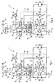
- Fig. 1 shows a first embodiment of the controller according to the invention.
- the controller 1 is designed to control the slewing gear of an excavator.
- An adjustable hydraulic pump 2 is connected via a drive shaft 50 to a drive motor, not shown, e.g. a diesel engine, connected. About a formed by the working lines 3 and 4 drive circuit of the hydraulic motor 5 is connected to the hydraulic pump 2 in connection.
- the hydraulic motor 5 drives via a drive shaft 6, not shown, the rotating mechanism of the excavator.
- the pressurized fluid of the drive circuit is fed via a feed device 7 which comprises a feed pump 8 also connected to the drive motor.
- the feed pump 8 continuously sucks in pressure fluid via a feed filter 9 from a pressure fluid tank 10 and feeds this into the feed line 11.
- the feed line 11 is connected via check valves 12 and 13 to the working lines 3 and 4 and feeds the pressurized fluid respectively into the low pressure leading working line 3 and 4 a.
- the feed pressure is regulated by pressure control valves 14 and 15. To limit the pressure in the feed line 11, the pressure relief valve 16 is used.
- the manual control transmitter 17 acts on one of the two control lines 20 or 21 with a control pressure as a function of its deflection. In the neutral position shown in Fig. 1 are both Control lines 20 and 21 via the manual control transmitter 17 to the pressurized fluid tank 10 vented out.
- control lines 20, 21 are connected via throttle bodies 22 and 23 and to be described in more detail brake valves 24 and 25, each with a control pressure chamber 26 and 27 of the adjusting device 28.
- an actuating piston 28a is arranged, which adjusts the displacement volume of the hydraulic pump 2 via a piston rod 29.
- the adjusting piston 28a is centered on centering springs 30 and 31 in its neutral position shown in FIG.
- the Nachsauge stimulating 32 consists of two check valves 33 and 34 and is used for vacuuming of pressurized fluid from the pressurized fluid tank 10 during the return of the actuating piston 28a in its neutral position.
- the brake valves 24 and 25 each have two control pressure chambers 35 and 36 and 37 and 38, respectively.
- the driving pressure chambers 36 and 37 are connected via a shuttle valve 39 to the two control lines 20 and 21.
- the control pressure chambers 35 and 38 opposite the control pressure chambers 36 and 37 are connected via working line connecting lines 40 and 41 to one of the two working lines 3 or 4, respectively.
- both control lines 20 and 21 are vented via the manual control transmitter 17 to the pressure fluid tank 10, so that the control pressure chambers 36 and 37 are depressurized.
- control piston 28a Since the control piston 28a is in its neutral position and therefore the hydraulic pump 2 operates with zero displacement, the working lines 3 and 4 are also depressurized, so that between the control pressure chambers 35 and 37 on the one hand and 36 and 38 on the other hand no pressure difference established.
- the brake valves 24 and 25 are therefore held by means of the adjustable compression springs 42 and 43 with their unthrottled switching positions 44 and 45.
- an adjustable pressure cut-off valve 47 is provided in the exemplary embodiment, which limits the pressure-carrying control line 20 and 21 to the pressure fluid tank 10 when a predetermined maximum pressure is exceeded.
- Another pressure relief valve 48 is actuated via a shuttle valve 49 from the working lines 3 and 4.
- Fig. 2 shows the hydraulic control in the acceleration phase.
- the control line 20 is acted upon by the control pressure filter 18 from the control pressure supply 19 with control pressure, while the other control line 21 is vented to the pressure fluid tank 10 out.
- the control pressure chamber 26 is acted upon by the control valve 24 via the brake valve, so that the control piston 28 a shifts in the direction indicated by the arrow 61.
- the hydraulic pump 2 is swung out accordingly and constructed in the working line 4, a corresponding high pressure to drive the hydraulic motor 5 in the desired direction of rotation. In this way, coupled to the hydraulic motor 5 slewing the excavator is accelerated.
- the brake valves 24 and 25 are in the unthrottled switching positions 44 and 45, since during the acceleration phase shown in Fig. 2 in the control line 20 and thus also in the control pressure chambers 36 and 37, a corresponding control pressure is the brake valves 24th and press 25 in their unthrottled positions.
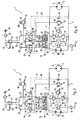
- Fig. 4 the operating state is shown in the deceleration phase in the event that the rotating mechanism is subjected to a resistance during the deceleration phase and the slewing gear can not rotate freely according to its moment of inertia.
- a resistance is particularly caused by the fact that the excavator (in which the slewing gear is located) is on an inclined plane, as occurs very frequently in the construction site area. If the slewing is braked in a rotation angle range in which the boom located on the slewing moves uphill, it comes due to the Hangabtriebs characteristic to a relatively rapid deceleration of the slewing gear.
- the pressure side change described above with reference to FIG. 3 does not occur in this case. Rather, the hydraulic motor 5 is still driven by the still deflected hydraulic pump 2. In the working line 4, therefore, a high pressure builds up in this operating state, while the working line 3 operates as a low-pressure reflux line.
- the hydraulic control according to the invention operates on the same principle.
- the brake valve 25 via the brake valve 25, the return flow of the pressure fluid from the charge pressure chamber 27 filled during the acceleration phase to the pressure fluid tank 10 in the deceleration phase is controlled as described above, while the shift position of the brake valve 24 is irrelevant.
- Fig. 5 shows a non-inventive example of a control in its neutral position. Also in this example, the controller 1 is designed to control the slewing gear of an excavator. Already described elements are provided with matching reference numerals, so that in this respect a repetitive description is unnecessary.
- the brake valves 24 and 25 each have a control pressure chamber 36 and 37, respectively.
- the driving pressure chambers 36 and 37 are connected via a shuttle valve 39 to the two control lines 20 and 21.
- the control pressure chambers 36 and 37 opposite each a return member in the form of a return spring 80 and 81 are provided.
- Each of the two brake valves 24 and 25 is therefore controlled by the force difference between a force exerted by the control pressure in the control pressure applied to the control line 20 and 21 and a force exerted by the respective return spring 80 and 81 restoring force.
- the two control lines 20 and 21 are vented via the manual control transmitter 17 to the pressure fluid tank 10, so that the control pressure chambers 36 and 37 are depressurized.
- the brake valves 24 and 25 are Therefore, switched by the return springs 80 and 81 in their respective throttled switching position 70 and 71, respectively.
- the hydraulic pump 2 is swung out in one of its conveying directions in accordance with the intended direction of rotation.
- the control line 20 or the control line 21 is applied via the control pressure filter 18 from the control pressure supply 19 with control pressure via the control stick 60 of the manual control transmitter 17, while the respective other control line is vented to the pressure fluid tank 10 out.
- the control pressure chamber 26 or the control pressure chamber 27 is acted upon via the brake valve 24 and the brake valve 25 with control pressure, so that the actuating piston 28a moves accordingly.
- the hydraulic pump 2 is swung out accordingly and constructed in one of the working lines 3 or 4, a corresponding high pressure to drive the hydraulic motor, not shown in Fig.
- the brake valves 24 and 25 are in the unthrottled switching positions 44 and 45, since during the acceleration phase in one of the two control lines 20 or 21 and thus also in the control pressure chambers 36 and 37, a corresponding control pressure is the brake valves 24 and 25 in their unthrottled switching positions 44 and 45 presses.
- the hydraulic pump 2 initially remains in position her swung out position.
- the pressurized fluid escapes from the actuating pressure chamber 26 or 27, which is acted upon by pressurized fluid during the acceleration phase, via the brake pressure valve 24 or 25 and the manual control transmitter 17 to the pressure fluid tank 10.
- the two brake valves 24 and 25 are now in their throttled switching position 70 and 71, since they are acted upon by the associated return spring 80 and 81 and the control pressure chambers 36 and 37 are substantially depressurized.
- the return flow of the pressure fluid from the respective control pressure chamber 26 or 27 is therefore throttled by the respective associated brake valve 24 and 25 respectively.
- the provision of the actuating piston 28 is therefore relatively slow, which manifests itself in a sensitive, hesitant deceleration of the slewing gear.
- the invention can also be used in conjunction with a precontrol, as is basically known from DE 44 05 472 A1.
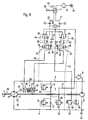
- Fig. 6 shows a hydraulic control according to the invention with another, advantageous embodiment for a pilot control.
- the illustrated in Fig. 6 second embodiment is designed similar to the non-inventive example shown in Fig. 5.
- Already described elements are provided with matching reference numerals, so that the following description refers only to the differences and peculiarities.
- the feeding device 7 is used in the embodiment shown in Fig. 6 not only for desserts the working cycle 2 to 4, but also for supplying pressurized fluid to the adjusting device 28.
- Each brake valve 24 and 25 is a respective pressure control valve 90, 91 associated, each upstream the associated brake valve 24, 25 is arranged.
- the pressure control valves 90 and 91 are connected on the one hand to the feed line 11 of the feed device 7 and on the other hand to the pressure fluid tank 10.
- Each pressure control valve 90, 91 is connected via a connecting line 92, 93 with the associated brake valve 24, 25.
- the control of the pressure control valve 90 and 91 is proportional to the pressure difference between the prevailing in the respective connecting line 92 and 93 actuating pressure and the control pressure in the associated control line 20 and 21.
- control inputs of the pressure control valve 90 and 91 via an associated detour line 94 or 95 connected to the connection line 92 and 93, respectively.
- a respective other control input of the pressure regulating valve 90 or 91 communicates with the associated control line 20 and 21, respectively.
- the control pressure prevailing in the connecting lines 92 and 93 is therefore essentially proportional to the control pressure prevailing in the associated control line 20 and 21, respectively.
- the compression springs 96 and 97 is achieved, however, that the control pressure slightly, e.g. 1 to 2 bar, above the ruling in the associated control line 20 and 21 control pressure.
- the control pressure prevailing in the respective control pressure chamber 26 or 27 is metered by the respective pressure control valve 90 or 91 substantially in proportion to the control pressure prevailing in the respective control line 20 and 21, respectively.
- the pressure fluid flows from the control pressure chamber 26 or 27 in the manner explained with reference to FIGS. 1 to 4 via the respective brake valve 24 or 25 via the respective pressure relief valve 90 and 91 to the pressure fluid tank 10.
- the Nachsauge pain 32 is not required in this embodiment, since the pressure fluid supply that Stelltikhunt whose volume increases in the provision in neutral position, via the feed device 7, the feed line 11 and the associated pressure control valve 90 and 91 and the associated brake valve 24 and 25 takes place.
- the advantage lies in the fact that no suction resistance is overcome, but via the feed pump 8 takes an active feed into the adjustment 28. Any contamination by dirt particles is safely and effectively avoided by the feed filter 9.
- brake valves 24 and 25 are not necessarily located directly in the control lines 20 and 21. They may be provided at any point in the return line between the control pressure chambers 26 and 27 and the pressure fluid tank.
Landscapes
- Engineering & Computer Science (AREA)
- General Engineering & Computer Science (AREA)
- Mining & Mineral Resources (AREA)
- Civil Engineering (AREA)
- Structural Engineering (AREA)
- Mechanical Engineering (AREA)
- Physics & Mathematics (AREA)
- Fluid Mechanics (AREA)
- Fluid-Pressure Circuits (AREA)
- Operation Control Of Excavators (AREA)
Abstract
Description
Die vorliegende Erfindung betrifft eine hydraulische Steuerung insbesondere zum Ansteuern des Drehwerks eines Baggers.The present invention relates to a hydraulic control, in particular for controlling the slewing gear of an excavator.
Eine hydraulische Steuerung nach dem Oberbegriff des Anspruches 1 ist aus der DE 44 05 472 A1 bekannt. Aus dieser Druckschrift geht eine hydraulische Steuerung zum Ansteuern eines Drehwerks mit einem Bremsventil hervor. Das Bremsventil dient zum feinfühligen Abbremsen des Drehwerks durch Steuern des Bremsmoments. Das Bremsventil verbindet eine die Stellvorrichtung ansteuernde Vorsteuereinrichtung mit dem Druckfluid-Tank. Dadurch wird der Rückfluß des Druckfluids aus der beim Beschleunigen des Drehwerks beaufschlagten Stelldruckkammer zum Druckfluid-Tank während des Abbremsens des Drehwerks gedrosselt und somit der Abbremsvorgang verzögert.A hydraulic control according to the preamble of claim 1 is known from
Nachteilig ist bei dieser bekannten hydraulischen Drehwerksteuerung jedoch, daß lediglich ein Bremsventil vorgesehen ist und daher der Rückfluß des Druckfluids aus den beiden Stelldruckkammern der Stellvorrichtung nicht unabhängig voneinander erfolgt. Dies kann die Zuverlässigkeit der hydraulischen Steuerung beeinflussen. Ferner ist bei dieser bekannten hydraulischen Drehwerksteuerung nachteilig, daß das Bremsventil auch dann anspricht, wenn der Drehbewegung des Drehwerks beim Abbremsen ein Widerstand entgegensteht. Ein solcher Widerstand wird z.B. dadurch hervorgerufen, daß sich der Bagger auf einer schiefen Ebene befindet und sich der Ausleger des Drehwerks während des Bremsvorganges bergauf bewegt. Diese Situation ist im Baustellenbereich mit naturgemäß unebenem Untergrund relativ häufig. Desweiteren entsteht ein entsprechender Widerstand, wenn der Ausleger des Drehwerks in ein Haufwerk od.dgl. hineinschwenkt.A disadvantage of this known hydraulic turntable control, however, that only one brake valve is provided and therefore the return flow of the pressurized fluid from the two actuating pressure chambers of the adjusting device is not independent of each other. This can affect the reliability of the hydraulic control. Furthermore, it is disadvantageous in this known hydraulic turntable control that the brake valve also responds when the rotational movement of the slewing gear during braking opposes a resistance. Such a resistance is caused, for example, that the excavator is on an inclined plane and moves the boom of the slewing during the braking process uphill. This situation is relatively common in construction sites with naturally uneven ground. Furthermore, a corresponding resistance arises when the boom of the slewing gear or the like in a heap. into pans.
In der DE 41 16 649 A 1 wird eine hydraulische Steuerung für eine hydraulische Maschine eines Fahrwerks in einem Bagger vorgestellt. Die hydraulische Steuerung besteht aus zwei Bremsventilen zur Einstellung eines definierten Bremsverhaltens für das Verzögern der hydraulischen Maschine in beiden Drehrichtungen. Die beiden Bremsventile sind dafür jeweils in den beiden Verbindungsleitungen zwischen einer der beiden Stelldruckkammer der Verstellvorrichtung und dem gemeinsamen Druckfluidtank geschaltet. Da die hydraulische Steuerung für einen Fahrantrieb ausgelegt ist, können mit dieser Anordnung die für ein Drehwerk charakteristischen Bremsvorgänge - widerstandsbehaftetes und widerstandsfreies Bremsen - nicht realisiert werden.In DE 41 16 649 A 1, a hydraulic control for a hydraulic machine of a chassis is presented in an excavator. The hydraulic control consists of two brake valves for setting a defined braking behavior for decelerating the hydraulic machine in both directions of rotation. For this purpose, the two brake valves are each connected in the two connecting lines between one of the two actuating pressure chamber of the adjusting device and the common pressure fluid tank. Since the hydraulic control is designed for a drive, with this arrangement, the characteristic of a slewing braking operations - resistive and resistance-free braking - can not be realized.
Es ist daher die Aufgabe der vorliegenden Erfindung, die bekannte Drehwerksteuerung so weiterzubilden, daß die Zuverlässigkeit erhöht wird.It is therefore the object of the present invention, the known turntable control so educate, that the reliability is increased.
Die Aufgabe wird durch die kennzeichnenden Merkmale des Anspruches 1 in Verbindung mit den gattungsbildenden Merkmalen gelöst.The object is achieved by the characterizing features of claim 1 in conjunction with the generic features.
Der Lösung nach Anspruch 1 liegt die Erkenntnis zugrunde, daß in den die Hydropumpe mit dem Hydromotor verbindenden Arbeitsleitungen ein Druckwechsel erfolgt, wenn sich das Drehwerk während des Abbremsvorganges widerstandsfrei weiterdrehen kann. Wenn das Drehwerk während des Abbremsvorgangs dagegen einem Widerstand z.B. durch die Hangabtriebskraft oder einen Anschlag ausgesetzt ist, bleibt dieser Druckseitenwechsel aus, d.h. die während der Beschleunigungsphase mit Hochdruck beaufschlagte Arbeitsleitung ist auch während des Bremsvorgangs mit Hochdruck beaufschlagt. Die Erfindung macht sich diese Erkenntnis dadurch zunutze, daß für jede der Stelldruckkammern jeweils ein separates Bremsventil vorgesehen ist, das jeweils mit einer der Arbeitsleitungen verbunden ist. Die Bremsventile werden dabei in Abhängigkeit von der Druckdifferenz zwischen dem Arbeitsdruck in der zugeordneten Arbeitsleitung und dem Steuerdruck angesteuert. Dabei spricht während des Bremsvorgangs bei im wesentlichen drucklosen Steuerleitungen nur dasjenige Bremsventil an, dessen zugeordnete Arbeitsleitung mit Hochdruck beaufschlagt ist.The solution according to claim 1 is based on the finding that in the hydropump connecting the hydraulic motor working lines a pressure change takes place when the slewing can continue to rotate without resistance during the braking process. On the other hand, if the slewing gear is subjected to a resistance during the deceleration process, e.g. is exposed by the slope force or a stop, this print page change remains, ie. the working line subjected to high pressure during the acceleration phase is also subjected to high pressure during the braking process. The invention makes use of this finding that for each of the control pressure chambers, a separate brake valve is provided in each case, which is in each case connected to one of the working lines. The brake valves are controlled in response to the pressure difference between the working pressure in the associated working line and the control pressure. It speaks during the braking process at substantially unpressurized control lines only that brake valve whose associated working line is subjected to high pressure.
Die Ansprüche 2 bis 10 beinhalten vorteilhafte Weiterbildungen der Erfindung.The
Entsprechend Anspruch 2 ist jedes Bremsventil mit derjenigen Arbeitsleitung verbunden, die bei dem dem Bremsvorgang vorhergehenden Ausschwenken der Hydropumpe die Niederdruck-Rücklaufleitung des Antriebskreislaufs bildet.According to
Die Bremsventile können entsprechend Anspruch 3 als Schaltventile mit einer gedrosselten und einer ungedrosselten Schaltstellung ausgebildet sein. Während der Beschleunigungsphase, in welcher die Steuerleitungen mit Steuerdruck beaufschlagt sind, befinden sich die Bremsventile in ihrer ungedrosselten Schaltstellung. Während der Abbremsphase, in der die Steuerleitungen im wesentlichen druckfrei sind, wird dasjenige Bremsventil in seine gedrosselte Schaltstellung geschaltet, dessen zugeordnete Arbeitsleitung mit Hochdruck beaufschlagt ist.The brake valves can be designed according to
Beim widerstandsfreien Abbremsen des Drehwerks findet in den Arbeitsleitungen ein Druckseitenwechsel statt, d.h. diejenige Arbeitsleitung, die während der Beschleunigungsphase die Niederdruck-Arbeitsleitung gebildet hat, bildet in der Abbremsphase die Hochdruck-Arbeitsleitung. Daher spricht dasjenige Abbremsventil an, dessen zugeordnete Stelldruckkammer während der Beschleunigungsphase mit Stelldruck beaufschlagt wurde. Wird das Drehwerk dagegen während des Abbremsvorgangs einem Widerstand ausgesetzt, so findet der Druckseitenwechsel nicht statt. Das Bremsventil, das derjenigen Stelldruckkammer zugeordnet ist, die während der Beschleunigungsphase mit Stelldruck beaufschlagt wurde, spricht in diesem Fall nicht an, so daß die entsprechende Stelldruckkammer über das in der ungedrosselten Schaltstellung befindende Bremsventil zügig entlastet werden kann. Dadurch wird ein unkontrolliertes Weiterschwenken des Drehwerks verhindert.When resistance-free braking of the slewing takes place in the working lines, a pressure side change, ie the working line that has formed the low-pressure working line during the acceleration phase, forms the high-pressure working line in the deceleration phase. Therefore responds to that Abbremsventil whose associated actuating pressure chamber was acted upon during the acceleration phase with control pressure. If, on the other hand, the slewing gear is subjected to resistance during the deceleration process, the pressure side change does not take place. The brake valve, which is associated with that control pressure chamber, which was acted upon during the acceleration phase with control pressure, does not respond in this case, so that the corresponding control pressure chamber can be quickly relieved via the brake valve located in the unthrottled switching position. This prevents uncontrolled further pivoting of the slewing gear.
Entsprechend Anspruch 4 können die Bremsventile jeweils zwei Ansteuer-Druckkammern aufweisen, wobei eine der Ansteuer-Druckkammer mit der zugeordneten Arbeitsleitung und die andere Ansteuer-Druckkammer mit den Steuerleitungen verbunden ist. Zur Auswahl derjenigen Steuerleitung, die den größeren Druck führt, kann entsprechend Anspruch 5 ein Wechselventil vorgesehen sein.According to
Entsprechend Anspruch 6 können die Bremsventile besonders vorteilhaft unmittelbar an den Steuerleitungen angeordnet sein, wobei entsprechend Anspruch 7 zwischen den Bremsventilen und den zugeordneten Stelldruckkammern eine Nachsaugeeinrichtung vorgesehen sein kann, um auf der Saugseite beim Rückstellen des Stellkolbens ein zügiges Nachfließen von Druckfluid zu gewährleisten.According to
Zur Begrenzung des Steuerdrucks in den Steuerleitungen auf einen Maximaldruck kann ferner entsprechend Anspruch 9 ein Druckabschneideventil vorgesehen sein.To limit the control pressure in the control lines to a maximum pressure may further be provided according to claim 9, a pressure cut valve.
Die Erfindung wird nachfolgend anhand eines bevorzugten Ausführungsbeispiels unter Bezugnahme auf die Zeichnung näher beschrieben. In der Zeichnung zeigen:
- Fig. 1
- ein erstes Ausführungsbeispiel der erfindungsgemäßen hydraulischen Steuerung in der Neutralstellung,
- Fig. 2
- das Ausführungsbeispiel entsprechend Figur 1 während der Beschleunigungsphase,
- Fig. 3
- das Ausführungsbeispiel entsprechend Figur 1 während der Verzögerungsphase, wenn das Drehwerk keinen Drehwiderstand erfährt,
- Fig. 4
- das Ausführungsbeispiel entsprechend Figur 1 während der Verzögerungsphase, wenn das Drehwerk einen Drehwiderstand erfährt,
- Fig. 5
- ein nicht erfindungsgemäßes Beispiel einer hydraulischen Steuerung in der Neutralstellung, und
- Fig. 6
- ein zweites Ausführungsbeispiel der erfindungsgemäßen hydraulischen Steuerung in der Neutralstellung.
- Fig. 1
- A first embodiment of the hydraulic control according to the invention in the neutral position,
- Fig. 2
- the embodiment according to FIG. 1 during the acceleration phase,
- Fig. 3
- the embodiment according to FIG. 1 during the deceleration phase, when the slewing gear does not undergo rotational resistance,
- Fig. 4
- the embodiment according to FIG. 1 during the deceleration phase, when the slewing gear experiences rotational resistance,
- Fig. 5
- a not inventive example of a hydraulic control in the neutral position, and
- Fig. 6
- A second embodiment of the hydraulic control according to the invention in the neutral position.
Fig. 1 zeigt ein erstes Ausführungsbeispiel der erfindungsgemäßen Steuerung. In den Ausführungsbeispielen ist die Steuerung 1 zur Ansteuerung des Drehwerks eines Baggers ausgelegt.Fig. 1 shows a first embodiment of the controller according to the invention. In the exemplary embodiments, the controller 1 is designed to control the slewing gear of an excavator.
Eine verstellbare Hydropumpe 2 ist über eine Antriebswelle 50 mit einem nicht dargestellten Antriebsmotor, z.B. einem Dieselmotor, verbunden. Über einen durch die Arbeitsleitungen 3 und 4 gebildeten Antriebskreislauf steht der Hydromotor 5 mit der Hydropumpe 2 in Verbindung. Der Hydromotor 5 treibt über eine Antriebswelle 6 das nicht dargestellte Drehwerk des Baggers an.An adjustable
Das Druckfluid des Antriebskreislaufs wird über eine Speiseeinrichtung 7 nachgespeist, die eine ebenfalls mit dem Antriebsmotor verbundene Speisepumpe 8 umfaßt. Die Speisepumpe 8 saugt über ein Speisefilter 9 aus einem Druckfluid-Tank 10 kontinuierlich Druckfluid nach und speist dieses in die Speiseleitung 11 ein. Die Speiseleitung 11 ist über Rückschlagventile 12 und 13 mit den Arbeitsleitungen 3 und 4 verbunden und speist das Druckfluid jeweils in die den Niederdruck führende Arbeitsleitung 3 bzw. 4 ein. Der Speisedruck wird durch Druckregelventile 14 und 15 eingeregelt. Zur Begrenzung des Drucks in der Speiseleitung 11 dient das Überdruckventil 16.The pressurized fluid of the drive circuit is fed via a
Die Ansteuerung des Verdrängungsvolumens der Hydropumpe 2 erfolgt über den Handsteuergeber 17, der mit dem Druckfluid-Tank 10 und über das Steuerdruckfilter 18 mit einer Steuerdruckeinspeisung 19 in Verbindung steht. Der Handsteuergeber 17 beaufschlagt in Abhängigkeit von seiner Auslenkung eine der beiden Steuerleitungen 20 oder 21 mit einem Steuerdruck. In der in Fig. 1 dargestellten Neutralstellung sind beide Steuerleitungen 20 und 21 über den Handsteuergeber 17 zu dem Druckfluid-Tank 10 hin belüftet.The control of the displacement volume of the
Die Steuerleitungen 20, 21 sind über Drosselstellen 22 und 23 und noch näher zu beschreibende Bremsventile 24 und 25 mit jeweils einer Stelldruckkammer 26 und 27 der Verstellvorrichtung 28 verbunden.The control lines 20, 21 are connected via
Zwischen den Stelldruckkammern 26 und 27 ist ein Stellkolben 28a angeordnet, der über eine Kolbenstange 29 das Verdrängungsvolumen der Hydropumpe 2 verstellt. Der Stellkolben 28a wird über Zentrierfedern 30 und 31 in seiner in Figur 1 dargestellten Neutralstellung zentriert.Between the
Zwischen jedem Bremsventil 24 und 25 und der diesem zugeordneten Stelldruckkammer 26 und 27 mündet eine Nachsaugeeinrichtung 32 in die Steuerleitungen 20 und 21 ein. Im dargestellten Ausführungsbeispiel besteht die Nachsaugeeinrichtung 32 aus zwei Rückschlagventilen 33 und 34 und dient zum Nachsaugen von Druckfluid aus dem Druckfluid-Tank 10 während der Rückführung des Stellkolbens 28a in seine Neutralstellung.Between each
Die Bremsventile 24 und 25 weisen jeweils zwei Ansteuer-Druckkammern 35 und 36 bzw. 37 und 38 auf. Die Ansteuer-Druckkammern 36 und 37 sind über ein Wechselventil 39 mit den beiden Steuerleitungen 20 und 21 verbunden. Die den Ansteuer-Druckkammern 36 und 37 gegenüberliegenden Ansteuer-Druckkammern 35 und 38 sind über Arbeitsleitungs-Verbindungsleitungen 40 und 41 mit jeweils einer der beiden Arbeitsleitungen 3 oder 4 verbunden. In der in Fig. 1 dargestellten Neutralstellung sind beide Steuerleitungen 20 und 21 über den Handsteuergeber 17 zu dem Druckfluid-Tank 10 hin belüftet, so daß die Ansteuer-Druckkammern 36 und 37 drucklos sind. Da sich der Stellkolben 28a in seiner Neutralstellung befindet und daher die Hydropumpe 2 mit Null-Verdrängungsvolumen arbeitet, sind die Arbeitsleitungen 3 und 4 ebenfalls drucklos, so daß sich zwischen den Ansteuer-Druckkammern 35 bzw. 37 einerseits und 36 bzw. 38 andererseits keine Druckdifferenz einstellt. Die Bremsventile 24 und 25 werden daher mittels der justierbaren Druckfedern 42 und 43 mit ihren ungedrosselten Schaltstellungen 44 und 45 gehalten.The
Zur Begrenzung des Steuerdrucks in den Steuerleitungen 20 und 21 nach den Drosselstellen 22 und 23 ist im Ausführungsbeispiel ein über einen Geber 46 einstellbares Druckabschneideventil 47 vorgesehen, das die druckführende Steuerleitung 20 bzw. 21 bei Überschreiten eines vorgegebenen Maximaldrucks zum Druckfluid-Tank 10 hin begrenzt. Ein weiteres Überdruckventil 48 wird über ein Wechselventil 49 von den Arbeitsleitungen 3 und 4 angesteuert.In order to limit the control pressure in the
Die Funktion der erfindungsgemäßen Bremsventile 24 und 25 des ersten Ausführungsbeispiels wird nachfolgend anhand der in den Figuren 2 bis 4 dargestellten Betriebszustände der hydraulischen Steuerung näher beschrieben.The function of the
Fig. 2 zeigt die hydraulische Steuerung in der Beschleunigungsphase. Durch Auslenken des Steuerknüppels 60 des Handsteuergebers 17 wird die Steuerleitung 20 über das Steuerdruckfilter 18 aus der Steuerdruckeinspeisung 19 mit Steuerdruck beaufschlagt, während die andere Steuerleitung 21 zu dem Druckfluid-Tank 10 hin belüftet wird. Dadurch wird die Stelldruckkammer 26 über das Bremsventil 24 mit Steuerdruck beaufschlagt, so daß sich der Stellkolben 28a in der durch den Pfeil 61 angedeuteten Richtung verschiebt. Die Hydropumpe 2 wird entsprechend ausgeschwenkt und in der Arbeitsleitung 4 ein entsprechender Hochdruck aufgebaut, um den Hydromotor 5 in der gewünschten Drehrichtung anzutreiben. Auf diese Weise wird das an den Hydromotor 5 gekoppelte Drehwerk des Baggers beschleunigt. Die Bremsventile 24 und 25 befinden sich dabei in den ungedrosselten Schaltstellungen 44 und 45, da während der in Fig. 2 dargestellten Beschleunigungsphase sich in der Steuerleitung 20 und somit auch in den Ansteuer-Druckkammern 36 und 37 ein entsprechender Steuerdruck befindet, der die Bremsventile 24 und 25 in ihre ungedrosselten Schaltstellungen drückt.Fig. 2 shows the hydraulic control in the acceleration phase. By deflecting the
Nach Erreichen der gewünschten Drehgeschwindigkeit kann der Steuerknüppel 60 von der Bedienperson losgelassen werden, so daß dieser in die in Fig. 3 dargestellte Neutralstellung zurückschwenkt. Daraufhin wird die Steuerleitung 20 als auch die Steuerleitung 21 zum Druckfluid-Tank 10 hin belüftet und der Steuerdruck in der Steuerleitung 20 abgebaut. Entsprechend werden auch die Ansteuer-Druckräume 36 und 37 der Bremsventile 24 und 25 nicht mehr mit Steuerdruck beaufschlagt.After reaching the desired rotational speed of the
Aufgrund des während der Beschleunigungsphase in die Stelldruckkammer 26 eingefüllten Druckfluids befindet sich die Hydropumpe 2 jedoch zunächst weiterhin in ihrer ausgelenkten Stellung. Sofern sich das an den Hydromotor 5 gekoppelte Drehwerk in dieser in Figur 3 dargestellten Verzögerungsphase frei drehen kann, ohne irgendwelchen Widerständen ausgesetzt zu sein, baut sich in der Arbeitsleitung 3 ein Druck auf, während der Druck in der Arbeitsleitung 4 unter den in der Arbeitsleitung 3 herrschenden Druck abfällt. Es tritt daher ein Druckseitenwechsel auf, wobei die während der Beschleunigungsphase als Niederdruck-Arbeitsleitung arbeitende Arbeitsleitung 3 nunmehr zur Hochdruck-Arbeitsleitung und die während der Beschleunigungsphase als Hochdruck-Arbeitsleitung dienende Arbeitsleitung 4 nunmehr zur Niederdruck-Arbeitsleitung geworden ist. Diesen Effekt macht sich die vorliegende Erfindung zunutze.However, due to the pressure fluid introduced into the actuating
Die über die Arbeitsleitungs-Verbindungsleitung 40 mit der Hochdruck-Arbeitsleitung 3 verbundene Ansteuer-Druckkammer 35 des Bremsventils 24 bewirkt nunmehr ein Umschalten des Bremsventils 24 in die gedrosselte Schaltstellung 70. In der in Figur 3 dargestellten Verzögerungsphase wird der Stellkolben 28a mittels der Zentrierfedern 26 und 27 in seine in Fig. 1 dargestellte Neutralstellung zurückgedrückt, was durch den Pfeil 72 angedeutet ist. Der Rückfluß des Druckfluids aus der Stelldruckkammer 26 über die Steuerleitung 20 zum Druckfluid-Tank 10 hin wird jedoch durch das in der Steuerleitung 20 befindliche Bremsventil 24 gedrosselt, da dieses Bremsventil 24 sich in seiner gedrosselten Schaltstellung 70 befindet. Die Rückstellung des Stellkolbens 28 erfolgt in diesem Betriebszustand daher relativ langsam, was sich in einem feinfühligen, zögerlichen Abbremsen des Drehwerks äußert.The connected via the working
Der sich in der Stelldruckkammer 27 durch die Rückführung des Stellkolbens 28 einstellende Unterdruck bewirkt ein Nachsaugen von Druckfluid aus dem Druckfluid-Tank 10 über die Nachsaugeeinrichtung 32. Dabei öffnet das Rückschlagventil 33.The self-adjusting in the
In Fig. 4 ist der Betriebszustand in der Verzögerungsphase für den Fall dargestellt, daß das Drehwerk während der Verzögerungsphase einem Widerstand ausgesetzt ist und sich das Drehwerk nicht entsprechend seinem Trägheitsmoment frei drehen kann. Ein solcher Widerstand wird insbesondere dadurch hervorgerufen, daß sich der Bagger (in welchem sich das Drehwerk befindet), auf einer schiefen Ebene steht, wie dies im Baustellenbereich sehr häufig vorkommt. Wenn das Drehwerk in einem Drehwinkelbereich abgebremst wird, in dem sich der an dem Drehwerk befindliche Ausleger bergauf bewegt, kommt es aufgrund der Hangabtriebskräfte zu einem relativ schnellen Abbremsen des Drehwerks. Der vorstehend anhand von Fig. 3 beschriebene Druckseitenwechsel tritt dabei nicht auf. Vielmehr wird der Hydromotor 5 durch die noch ausgelenkte Hydropumpe 2 weiterhin angetrieben. In der Arbeitsleitung 4 baut sich in diesem Betriebszustand daher ein Hochdruck auf, während die Arbeitsleitung 3 als Niederdruck-Rückflußleitung arbeitet.In Fig. 4, the operating state is shown in the deceleration phase in the event that the rotating mechanism is subjected to a resistance during the deceleration phase and the slewing gear can not rotate freely according to its moment of inertia. Such a resistance is particularly caused by the fact that the excavator (in which the slewing gear is located) is on an inclined plane, as occurs very frequently in the construction site area. If the slewing is braked in a rotation angle range in which the boom located on the slewing moves uphill, it comes due to the Hangabtriebskräfte to a relatively rapid deceleration of the slewing gear. The pressure side change described above with reference to FIG. 3 does not occur in this case. Rather, the hydraulic motor 5 is still driven by the still deflected
In dem in Fig. 4 dargestellten Betriebszustand wird daher nicht das Bremsventil 24, sondern das mit der in diesem Fall mit Hochdruck beaufschlagten Arbeitsleitung 4 verbundene Bremsventil 25 in seine gedrosselte Schaltstellung 71 geschoben. Erfindungswesentlich ist, daß das Schaltventil 24 im Gegensatz zu dem anhand von Figur 3 erläuterten Betriebszustand in seiner ungedrosselten Schaltstellung 44 verbleibt. Das in die Stelldruckkammer 26 während der Beschleunigungsphase eingefüllte Druckfluid kann während des Rückstellens des Stellkolbens 28a in seine Neutralstellung mittels der Zentrierfedern 30 und 31 daher relativ rasch über das ungedrosselte Bremsventil 24 und die Steuerleitung 20 zum Druckfluid-Tank 10 hin entweichen.In the operating state shown in Fig. 4, therefore, not the
Die Schaltstellung des anderen Bremsventils 25 ist in diesem Betriebszustand ohne Bedeutung, da das in die Stelldruckkammer 27 nachfließende Druckfluid nicht über das Bremsventil 25, sondern über die Nachsaugeeinrichtung 32, d.h. über das geöffnete Rückschlagventil 33, aus dem Druckfluid-Tank 10 nachgesaugt wird. Der Stellkolben 28a wird daher im Gegensatz zu dem in Figur 3 dargestellten Betriebszustand relativ rasch in seine in Figur 1 dargestellte Neutralstellung zurückgeführt. Dies bedingt ein relativ rasches Zurückschwenken der Hydropumpe 2 auf Null-Verdrängungsvolumen, so daß der Hydromotor 5 von dieser nicht weiterhin angetrieben wird. Dadurch wird ein unkontrolliertes Weiterschwenken des Drehwerks in diesem Betriebszustand wirksam verhindert.The switching position of the
Dies ist insbesondere auch dann wesentlich, wenn der Ausleger des Drehwerks auf einen starren Widerstand trifft, in dem der Ausleger an einem Haufwerk od.dgl. anschlägt.This is especially important when the boom of the slewing meets a rigid resistance in which the boom or the like on a pile. strikes.
Wenn die Hydropumpe 2 in die umgekehrte Förderrichtung ausgeschwenkt wird, indem während der Beschleunigungsphase mittels des Handsteuergebers 17 die Steuerleitung 21 mit Steuerdruck beaufschlagt wird, arbeitet die erfindungsgemäße hydraulische Steuerung nach dem gleichen Prinzip. Jedoch wird in diesem Fall über das Bremsventil 25 der Rückfluß des Druckfluids aus der während der Beschleunigungsphase befüllten Stelldruckkammer 27 zum Druckfluid-Tank 10 hin in der Verzögerungsphase wie vorstehend beschrieben gesteuert, während die Schaltstellung des Bremsventils 24 dann ohne Bedeutung ist.When the
Fig. 5 zeigt ein nicht erfindungsgemäßes Beispiel einer Steuerung in ihrer Neutralstellung. Auch in diesem Beispiel ist die Steuerung 1 zur Ansteuerung des Drehwerks eines Baggers ausgelegt. Bereits beschriebene Elemente sind mit übereinstimmenden Bezugszeichen versehen, so daß sich diesbezüglich eine wiederholende Beschreibung erübrigt.Fig. 5 shows a non-inventive example of a control in its neutral position. Also in this example, the controller 1 is designed to control the slewing gear of an excavator. Already described elements are provided with matching reference numerals, so that in this respect a repetitive description is unnecessary.
Die Bremsventile 24 und 25 weisen im in Fig. 5 dargestellten Beispiel jeweils eine Ansteuerung-Druckkammer 36 bzw. 37 auf. Die Ansteuer-Druckkammern 36 und 37 sind über ein Wechselventil 39 mit den beiden Steuerleitungen 20 und 21 verbunden. Den Ansteuerdruckkammern 36 und 37 gegenüberliegend sind jeweils ein Rückstellglied in Form einer Rückstellfeder 80 bzw. 81 vorgesehen. Jedes der beiden Bremsventile 24 bzw. 25 wird daher durch die Kraftdifferenz zwischen einer von dem Steuerdruck in der mit größerem Steuerdruck beaufschlagte Steuerleitung 20 bzw. 21 ausgeübten Stellkraft und einer von der jeweiligen Rückstellfeder 80 bzw. 81 ausgeübten Rückstellkraft angesteuert. In der in Fig. 5 dargestellten Neutralstellung sind die beiden Steuerleitungen 20 und 21 über den Handsteuergeber 17 zu dem Druckfluid-Tank 10 hin belüftet, so daß die Ansteuer-Druckkammern 36 und 37 drucklos sind. Die Bremsventile 24 und 25 werden daher durch die Rückstellfedern 80 und 81 in ihre jeweilige gedrosselte Schaltstellung 70 bzw. 71 geschaltet.In the example shown in FIG. 5, the
Nachfolgend wird die Funktion der erfindungsgemäßen Bremsventile 24 und 25 gemäß dem in Fig. 5 dargestellten Beispiel näher beschrieben.Hereinafter, the function of the
Zum Beschleunigen des Drehwerks des Baggers wird entsprechend dem beabsichtigten Drehsinn die Hydropumpe 2 in eine ihrer Förderrichtungen ausgeschwenkt. Dazu wird über den Steuerknüppel 60 des Handsteuergebers 17 die Steuerleitung 20 oder die Steuerleitung 21 über das Steuerdruckfilter 18 aus der Steuerdruckeinspeisung 19 mit Steuerdruck beaufschlagt, während die jeweils andere Steuerleitung zu dem Druckfluid-Tank 10 hin belüftet wird. Dadurch wird die Stelldruckkammer 26 oder die Stelldruckkammer 27 über das Bremsventil 24 bzw. das Bremsventil 25 mit Steuerdruck beaufschlagt, so daß sich der Stellkolben 28a entsprechend verschiebt. Die Hydropumpe 2 wird entsprechend ausgeschwenkt und in einer der Arbeitsleitungen 3 oder 4 ein entsprechender Hochdruck aufgebaut, um den in Fig. 5 nicht dargestellten Hydromotor in der gewünschten Drehrichtung anzutreiben und das Drehwerk des Baggers zu beschleunigen. Die Bremsventile 24 und 25 befinden sich dabei in den ungedrosselten Schaltstellungen 44 und 45, da sich während der Beschleunigungsphase in einer der beiden Steuerleitungen 20 oder 21 und somit auch in den Ansteuer-Druckkammern 36 und 37 ein entsprechender Steuerdruck befindet, der die Bremsventile 24 und 25 in ihre ungedrosselten Schaltstellungen 44 bzw. 45 drückt.To accelerate the rotating mechanism of the excavator, the
Nach Erreichen der gewünschten Drehgeschwindigkeit kann der Steuerknüppel 60 von der Bedienperson losgelassen werden, so daß dieser in seine Neutralstellung zurückschwenkt. Daraufhin wird die Steuerleitung 20 als auch die Steuerleitung 21 zum Druckfluid-Tank 10 hin belüftet und der Steuerdruck in den Steuerleitungen 20, 21 abgebaut. Entsprechend werden auch die Ansteuer-Druckräume 36 und 37 der Bremsventile 24 und 25 nicht länger mit Steuerdruck beaufschlagt.After reaching the desired rotational speed of the
Aufgrund des während der Beschleunigungsphase in eine der Stelldruckkammern 26 oder 27 eingefüllten Druckfluids befindet sich die Hydropumpe 2 jedoch zunächst weiterhin in ihrer ausgeschwenkten Stellung. Das Druckfluid entweicht aus der während der Beschleunigungsphase mit Druckfluid beaufschlagte Stelldruckkammer 26 oder 27 über das der Stelldruckkammer zugeordnete Bremsventil 24 bzw. 25 und den Handsteuergeber 17 zum Druckfluid-Tank 10 hin. Dabei befinden sich die beiden Bremsventile 24 und 25 nunmehr in ihrer gedrosselten Schaltstellung 70 bzw. 71, da diese von der zugeordneten Rückstellfeder 80 bzw. 81 beaufschlagt werden und die Ansteuer-Druckkammern 36 und 37 im wesentlichen drucklos sind. Der Rückfluß des Druckfluids aus der jeweiligen Stelldruckkammer 26 bzw. 27 wird daher durch das jeweils zugeordnete Bremsventil 24 bzw. 25 gedrosselt. Die Rückstellung des Stellkolbens 28 erfolgt daher relativ langsam, was sich in einem feinfühligen, zögerlichen Abbremsen des Drehwerks äußert.However, because of the pressure fluid introduced into one of the
Der sich in der während der Beschleunigungsphase nicht mit Stelldruck beaufschlagten Stelldruckkammer durch die Rückführung des Stellkolbens 28 einstellende Unterdruck bewirkt ein Nachsaugen von Druckfluid aus dem Druckfluid-Tank 10 über die Nachsaugeeinrichtung 32. Dabei öffnet das jeweilige Rückschlagventil 33 bzw. 34.The in the during the acceleration phase not acted upon by adjusting pressure adjusting pressure chamber by the return of the
Durch die Zuordnung eines jeweils separaten Bremsventils 24 bzw. 25 jeder Stelldruckkammern 26 und 27 der Verstellvorrichtung wird die Betriebssicherheit der Drehwerksteuerung erheblich verbessert, ohne den Aufwand wesentlich zu erhöhen. Durch die Anordnung der Bremsventile 24 und 25 unmittelbar an den Steuerleitungen 20 und 21 wird ein besonders schnelles Ansprechen der Bremsventile 24 und 25 erreicht.By assigning a
Des weiteren läßt sich die Erfindung auch in Verbindung mit einer Vorsteuerung verwenden, so wie dies grundsätzlich aus der DE 44 05 472 A1 bekannt ist.Furthermore, the invention can also be used in conjunction with a precontrol, as is basically known from
Fig. 6 zeigt eine erfindungsgemäße hydraulische Steuerung mit einem anderen, zweckmäßigen Ausführungsbeispiel für eine Vorsteuerung. Das in Fig. 6 veranschaulichte zweite Ausführungsbeispiel ist ähnlich gestaltet wie das in Fig. 5 dargestellte nicht erfindungsgemäße Beispiel. Bereits beschriebene Elemente sind dabei mit übereinstimmenden Bezugszeichen versehen, so daß sich die nachfolgende Beschreibung sich lediglich auf die Unterschiede und Besonderheiten bezieht.Fig. 6 shows a hydraulic control according to the invention with another, advantageous embodiment for a pilot control. The illustrated in Fig. 6 second embodiment is designed similar to the non-inventive example shown in Fig. 5. Already described elements are provided with matching reference numerals, so that the following description refers only to the differences and peculiarities.
Die Speiseeinrichtung 7 dient bei dem in Fig. 6 dargestellten Ausführungsbeispiel nicht nur zum Nachspeisen des Arbeitskreislaufs 2 bis 4, sondern auch zum Zuführen von Druckfluid an die Verstellvorrichtung 28. Jedem Bremsventil 24 und 25 ist jeweils ein Druckregelventil 90, 91 zugeordnet, welches jeweils stromaufwärts des zugeordneten Bremsventils 24, 25 angeordnet ist. Die Druckregelventile 90 und 91 sind einerseits mit der Speiseleitung 11 der Speiseeinrichtung 7 und andererseits mit dem Druckfluid-Tank 10 verbunden. Jedes Druckregelventil 90, 91 ist über eine Verbindungsleitung 92, 93 mit dem zugeordneten Bremsventil 24, 25 verbunden. Die Ansteuerung des Druckregelventils 90 bzw. 91 erfolgt proportional zu der Druckdifferenz zwischen dem in der jeweiligen Verbindungsleitung 92 bzw. 93 herrschenden Stelldruck und dem Steuerdruck in der zugeordneten Steuerleitung 20 bzw. 21. Dazu ist jeweils einer der Steuereingänge des Druckregelventils 90 bzw. 91 über eine zugeordnete Umwegleitung 94 bzw. 95 mit der Verbindungsleitung 92 bzw. 93 verbunden. Ein jeweils anderer Steuereingang des Druckregelventils 90 bzw. 91 steht mit der zugeordneten Steuerleitung 20 bzw. 21 in Verbindung. Der in den Verbindungsleitungen 92 und 93 herrschende Stelldruck ist daher im wesentlichen dem in der zugeordneten Steuerleitung 20 bzw. 21 herrschenden Steuerdruck proportional. Durch die Druckfedern 96 und 97 wird jedoch erreicht, daß der Stelldruck geringfügig, z.B. 1 bis 2 bar, über dem in der zugeordneten Steuerleitung 20 bzw. 21 herrschenden Steuerdruck liegt.The
Während der Beschleunigungsphase wird der in der jeweiligen Stelldruckkammer 26 bzw. 27 herrschende Stelldruck durch das jeweilige Druckregelventil 90 bzw. 91 im wesentlichen proportional zu dem in der jeweiligen Steuerleitung 20 bzw. 21 herrschenden Steuerdruck zugemessen. In der Verzögerungsphase fließt das Druckfluid aus der Stelldruckkammer 26 bzw. 27 in der anhand der Fig. 1 bis 4 erläuterten Weise über das jeweilige Bremsventil 24 oder 25 über das jeweilige Druckbegrenzungsventil 90 bzw. 91 zum Druckfluid-Tank 10 zurück.During the acceleration phase, the control pressure prevailing in the respective
Die Nachsaugeeinrichtung 32 ist bei diesem Ausführungsbeispiel nicht erforderlich, da die Druckfluid-Versorgung derjenigen Stelldruckkammer, deren Volumen sich bei der Rückstellung in Neutralstellung vergrößert, über die Speiseeinrichtung 7, die Speiseleitung 11 und das zugeordnete Druckregelventil 90 bzw. 91 sowie das zugeordnete Bremsventil 24 bzw. 25 erfolgt. Der Vorteil liegt insbesondere darin, daß kein Saugwiderstand zu überwinden ist, sondern über die Speisepumpe 8 eine aktive Einspeisung in die Verstellvorrichtung 28 erfolgt. Eine eventuelle Verunreinigung durch Schmutzpartikel wird durch das Speisefilter 9 sicher und wirkungsvoll vermieden. Grundsätzlich ist es auch möglich, ein Nachsaugefilter in der passiven Nachsaugeeinrichtung 32 vorzusehen. Jedoch ist dieses gegenüber dem Speisefilter 9 wesentlich größer zu dimensionieren, um den Saugwiderstand möglichst gering zu halten. Dies steht jedoch nicht mit dem Ziel einer möglichst kompakten Bauweise im Einklang.The
Die Erfindung ist nicht auf das dargestellte Ausführungsbeispiel begrenzt. Insbesondere sind die Bremsventile 24 und 25 nicht notwendigerweise unmittelbar in den Steuerleitungen 20 und 21 anzuordnen. Sie können an beliebiger Stelle in der Rückflußleitung zwischen den Stelldruckkammern 26 und 27 und dem Druckfluid-Tank vorgesehen sein.The invention is not limited to the illustrated embodiment. In particular, the
Claims (10)
- Hydraulic controller, in particular for the control of the rotating mechanism of an excavator, having
a hydraulic drive circuit (2 - 4) with a hydraulic pump (2) and a hydraulic motor (5), and a first and a second working line (3, 4) connecting the hydraulic pump (2) with the hydraulic motor (5),
an adjustment arrangement (28) for adjusting a setting piston (28a), arranged between two setting pressure chambers (26, 27), acting on the displacement volume of the hydraulic pump (2), in dependence upon the pressure difference between two control lines (20, 21) and
at least one brake valve which, with disappearing control pressure in the control lines (20, 21), throttles the return flow of the pressure fluid out of the setting pressure chambers (26, 27) into the pressure fluid tank (10),
characterized in that,
a respective separate brake valve (24; 25) is associated with each connection between each of the two setting pressure chambers (26; 27) with the pressure fluid tank (10),
whereby a first of the two brake valves (24) is controlled by means of the pressure difference between the working pressure in the first working line (3) and the control pressure in the control line (20, 21) acted upon by the greater pressure, and
the second of the two brake valves (25) is controlled by means of the pressure difference between the working pressure in the second working line (4) and the control pressure in the control line (20, 21) acted upon by the greater pressure. - Hydraulic controller according to claim 1,
characterized in that,
each brake valve (24; 25) is respectively connected with that working line (3; 4) which upon swinging out of the hydraulic pump (2) by means of action upon the setting pressure chamber (26; 27) associated with the brake valve (24; 25) forms the low pressure return line (3; 4) of the drive circuit (3,4). - Hydraulic controller according to claim 1 or 2,
characterized in that,
each brake valve (24; 25) is formed as a switching valve having a first switching position (44; 45) with non-throttled through-flow and a second switching position (70; 71) with throttled through-flow
whereby the brake valve (24; 25) is in the first switching position (44; 45) when the pressure difference between the working pressure in the associated working line (3; 4) and the control pressure in the control line (20, 21) acted upon with the greater pressure is smaller than a predetermined threshold value, and
the brake valve (24; 25) is in the second switching position (70; 71) when the pressure difference between the working pressure in the associated working line (3; 4) and the control pressure in the control line (20, 21) acted upon with the greater pressure is greater than the predetermined threshold value. - Hydraulic controller according to any of claims 1 to 3,
characterized in that,
each brake valve (24; 25) has two control pressure chambers (35, 36; 37, 38), whereby a first control pressure chamber (35; 38) is connected with the associated working line (3; 4) and the second control pressure chamber (36; 37) is connected with the control lines (20, 21). - Hydraulic controller according claim 4,
characterized in that,
the two control pressure chambers (36, 37) are connected with the control lines (20, 21) via a change-over valve (39). - Hydraulic controller according to any of claims 1 to 5,
characterized in that,
the brake valves (24, 25) are arranged in the control lines (20, 21). - Hydraulic controller according claim 6,
characterized in that,
an after-suction arrangement (32), for the after-suction of pressure fluid out of the pressure fluid tank (10), is provided between the brake valves (24; 25) and the associated setting pressure chambers (26, 27). - Hydraulic controller according to any of claims 1 to 7,
characterized in that,
the control lines (20, 21) can be alternately acted upon with control pressure or vented to the pressure fluid tank (10) via a controller (17) connected with the pressure fluid tank (10) and a control pressure in-feed (19). - Hydraulic controller according to any of claims 1 to 8,
characterized in that,
a pressure cut-off valve (47) is provided for limiting the control pressure in the control lines (20, 21) to a maximum pressure. - Hydraulic controller according to any of claims 1 to 9,
characterized in that,
a feed arrangement (7) is provided for the feed-in of pressure fluid into the working circuit (2 - 4),
in that a respective pressure regulation valve (90; 91) is associated with each brake valve (24; 25) and
in that a setting pressure can be supplied to the setting pressure chamber (26, 27) associated with the respective brake valve (24; 25), via the respective brake valve (24; 25), which setting pressure is regulated by the associated pressure regulation valve (90; 91) in dependence upon the control pressure prevailing in an associated control line (20; 21).
Applications Claiming Priority (5)
| Application Number | Priority Date | Filing Date | Title |
|---|---|---|---|
| DE1996120664 DE19620664C1 (en) | 1996-05-22 | 1996-05-22 | Hydraulic control circuit for dredger slewing gear |
| DE19620664 | 1996-05-22 | ||
| DE19625393 | 1996-06-25 | ||
| DE19625393A DE19625393A1 (en) | 1996-05-22 | 1996-06-25 | Slewing gear control with double-sided braking |
| PCT/EP1997/002570 WO1997044536A1 (en) | 1996-05-22 | 1997-05-20 | Rotary mechanism control system with bilateral braking |
Publications (3)
| Publication Number | Publication Date |
|---|---|
| EP0904468A1 EP0904468A1 (en) | 1999-03-31 |
| EP0904468B1 EP0904468B1 (en) | 2002-03-13 |
| EP0904468B2 true EP0904468B2 (en) | 2007-03-14 |
Family
ID=26025936
Family Applications (1)
| Application Number | Title | Priority Date | Filing Date |
|---|---|---|---|
| EP97923950A Expired - Lifetime EP0904468B2 (en) | 1996-05-22 | 1997-05-20 | Rotary mechanism control system with bilateral braking |
Country Status (5)
| Country | Link |
|---|---|
| US (1) | US6082107A (en) |
| EP (1) | EP0904468B2 (en) |
| JP (1) | JP3446834B2 (en) |
| DE (2) | DE19625393A1 (en) |
| WO (1) | WO1997044536A1 (en) |
Families Citing this family (14)
| Publication number | Priority date | Publication date | Assignee | Title |
|---|---|---|---|---|
| DE19735111C2 (en) * | 1997-08-13 | 1999-06-02 | Brueninghaus Hydromatik Gmbh | Slewing gear control with brake and control valves |
| DE19833489A1 (en) * | 1998-07-24 | 2000-01-27 | Mannesmann Rexroth Ag | Hydraulic circuit for controlling user of work apparatus has pump supplying user with pressure medium via feed conduit with back flow conduit feeding back to tank |
| DE10000110B4 (en) * | 2000-01-04 | 2004-06-24 | Sauer-Sundstrand Gmbh & Co. | Hydrostatic vehicle drive with control device and control device for hydrostatic drives |
| US6644335B2 (en) * | 2000-12-15 | 2003-11-11 | Caterpillar S.A.R.L. | Precision orificing for pilot operated control valves |
| EP1225281B1 (en) * | 2001-01-23 | 2008-01-16 | Brueninghaus Hydromatik Gmbh | Hydraulic control, in particular for controlling the turning mechanism of an excavator |
| US7165396B2 (en) * | 2003-07-11 | 2007-01-23 | Eaton Corporation | Pump control override for tandem pumps |
| DE10343016B4 (en) * | 2003-09-17 | 2010-08-26 | Brueninghaus Hydromatik Gmbh | Hydraulic control and positioning system with volume compensation |
| US6964163B2 (en) * | 2003-11-10 | 2005-11-15 | Sauer-Danfoss, Inc. | Dual check-relief valve |
| US7726125B2 (en) * | 2007-07-31 | 2010-06-01 | Caterpillar Inc. | Hydraulic circuit for rapid bucket shake out |
| DE102007056991B4 (en) * | 2007-11-27 | 2014-05-08 | Sauer-Danfoss Gmbh & Co. Ohg | Hydraulic circuit arrangement with a device for zero-stroke pressure control and method for pressure control in zero-stroke operation |
| DE102011015286A1 (en) * | 2011-03-28 | 2012-10-04 | Liebherr-Werk Nenzing Gmbh | Hydraulic brake device for a crane drive and crane |
| US10794480B2 (en) * | 2014-08-07 | 2020-10-06 | Kanzaki Kokyukoki Mfg. Co., Ltd. | Control mechanism for stepless transmission |
| DE102016002613B4 (en) * | 2016-03-03 | 2022-09-29 | Liebherr-Werk Ehingen Gmbh | Hydraulic control circuit for a crane slewing gear |
| US10662980B2 (en) | 2017-10-03 | 2020-05-26 | Kubota Corporation | Hydraulic system in work machine |
Family Cites Families (10)
| Publication number | Priority date | Publication date | Assignee | Title |
|---|---|---|---|---|
| US3921503A (en) | 1972-03-21 | 1975-11-25 | Philip A Kubik | Control system for a fluid system |
| US4571941A (en) * | 1980-12-27 | 1986-02-25 | Hitachi Construction Machinery Co, Ltd. | Hydraulic power system |
| JPS57184749A (en) * | 1981-05-01 | 1982-11-13 | Hitachi Constr Mach Co Ltd | Control device for hydraulic system |
| JPS57184748A (en) * | 1981-05-01 | 1982-11-13 | Hitachi Constr Mach Co Ltd | Apparatus for controlling hydraulic system |
| US4554991A (en) * | 1984-02-23 | 1985-11-26 | Mud Hog Corporation | Auxiliary hydraulic drive system for road graders and the like |
| JPH0663264B2 (en) * | 1984-07-20 | 1994-08-22 | 株式会社小松製作所 | Swing energy recovery and reuse device for swiveling construction machinery |
| JPH02195074A (en) * | 1989-01-23 | 1990-08-01 | Kubota Ltd | Hydraulic structure of vehicle |
| DE4116649A1 (en) * | 1991-05-22 | 1992-11-26 | Linde Ag | Control for vehicle hydrostatic drive - has valves responsive to control pressure in connecting pipes for pump |
| DE4231637C2 (en) * | 1992-09-22 | 1995-10-12 | Orenstein & Koppel Ag | Braking device for a part that can be moved via a drive |
| DE4405472A1 (en) * | 1994-02-11 | 1995-08-17 | Caterpillar Inc | Hydraulic control for excavator with several hydraulic user units |
-
1996
- 1996-06-25 DE DE19625393A patent/DE19625393A1/en not_active Ceased
-
1997
- 1997-05-20 EP EP97923950A patent/EP0904468B2/en not_active Expired - Lifetime
- 1997-05-20 US US09/142,931 patent/US6082107A/en not_active Expired - Fee Related
- 1997-05-20 JP JP54154097A patent/JP3446834B2/en not_active Expired - Fee Related
- 1997-05-20 DE DE59706613T patent/DE59706613D1/en not_active Expired - Fee Related
- 1997-05-20 WO PCT/EP1997/002570 patent/WO1997044536A1/en not_active Ceased
Also Published As
| Publication number | Publication date |
|---|---|
| WO1997044536A1 (en) | 1997-11-27 |
| DE59706613D1 (en) | 2002-04-18 |
| US6082107A (en) | 2000-07-04 |
| DE19625393A1 (en) | 1998-01-02 |
| EP0904468B1 (en) | 2002-03-13 |
| JP3446834B2 (en) | 2003-09-16 |
| EP0904468A1 (en) | 1999-03-31 |
| JP2000510935A (en) | 2000-08-22 |
Similar Documents
| Publication | Publication Date | Title |
|---|---|---|
| EP0137184B1 (en) | Hydraulic system with a constant-delivery pump | |
| DE19934782C2 (en) | Method and arrangement for controlling a hydraulic vehicle drive | |
| EP0904468B2 (en) | Rotary mechanism control system with bilateral braking | |
| DE3934641C2 (en) | ||
| EP0826110B1 (en) | Sliding hydraulic output and moment regulation device | |
| EP0144788B1 (en) | Control mechanism for a variable delivery hydraulic transmission | |
| EP0137185A2 (en) | Hydraulic system with a variable-delivery pump and a priority valve | |
| DE2449464A1 (en) | HYDROSTATIC VEHICLE TRANSMISSION | |
| EP0137186B1 (en) | Hydraulic system comprising a constant-delivery pump and a priority valve | |
| DE2528094A1 (en) | CONTROL SYSTEM FOR HYDROSTATIC TRANSMISSION | |
| EP0904467B1 (en) | Rotary mechanism control with power supply | |
| DE2363762C2 (en) | Control device for a hydrostatic motor vehicle transmission | |
| EP0141074A2 (en) | Hydraulic system with a pump, a valve, a supply pipe and a control pipe | |
| DE3302546C2 (en) | Hydrostatic drive system connected to an internal combustion engine | |
| DE19850162C1 (en) | Hydrostatic transmission | |
| DE4420704C2 (en) | Hydrostatic drive, especially for the slewing gear of an excavator | |
| DE1630105C3 (en) | Hydrostatic transmission for automobiles | |
| DE3040321A1 (en) | CONTROL DEVICE FOR AUTOMOTIVE CONTROL OF AN ADJUSTABLE HYDROPUMP OF A HYDROSTAT IN A DRIVE DRIVE | |
| DE19620664C1 (en) | Hydraulic control circuit for dredger slewing gear | |
| DE2532768B2 (en) | Hydraulic servo motor system | |
| EP0456175B1 (en) | Hydrostatic drive system for vehicles | |
| DE3001681A1 (en) | CONTROL DEVICE FOR A HYDROSTATIC GEARBOX | |
| DE4140860C2 (en) | Control device for a hydrostatic transmission | |
| DE2335247A1 (en) | CONTROL DEVICE FOR A HYDROSTATIC MOTOR VEHICLE TRANSMISSION | |
| DE10220376B4 (en) | Hydraulic control with active reset |
Legal Events
| Date | Code | Title | Description |
|---|---|---|---|
| PUAI | Public reference made under article 153(3) epc to a published international application that has entered the european phase |
Free format text: ORIGINAL CODE: 0009012 |
|
| 17P | Request for examination filed |
Effective date: 19980717 |
|
| AK | Designated contracting states |
Kind code of ref document: A1 Designated state(s): DE FR GB IT SE |
|
| GRAG | Despatch of communication of intention to grant |
Free format text: ORIGINAL CODE: EPIDOS AGRA |
|
| GRAG | Despatch of communication of intention to grant |
Free format text: ORIGINAL CODE: EPIDOS AGRA |
|
| GRAH | Despatch of communication of intention to grant a patent |
Free format text: ORIGINAL CODE: EPIDOS IGRA |
|
| 17Q | First examination report despatched |
Effective date: 20010711 |
|
| GRAH | Despatch of communication of intention to grant a patent |
Free format text: ORIGINAL CODE: EPIDOS IGRA |
|
| REG | Reference to a national code |
Ref country code: GB Ref legal event code: IF02 |
|
| GRAA | (expected) grant |
Free format text: ORIGINAL CODE: 0009210 |
|
| AK | Designated contracting states |
Kind code of ref document: B1 Designated state(s): DE FR GB IT SE |
|
| REF | Corresponds to: |
Ref document number: 59706613 Country of ref document: DE Date of ref document: 20020418 |
|
| GBT | Gb: translation of ep patent filed (gb section 77(6)(a)/1977) |
Effective date: 20020617 |
|
| ET | Fr: translation filed | ||
| PLBI | Opposition filed |
Free format text: ORIGINAL CODE: 0009260 |
|
| PLBF | Reply of patent proprietor to notice(s) of opposition |
Free format text: ORIGINAL CODE: EPIDOS OBSO |
|
| 26 | Opposition filed |
Opponent name: LINDE AKTIENGESELLSCHAFT, WIESBADEN Effective date: 20021211 |
|
| PLBF | Reply of patent proprietor to notice(s) of opposition |
Free format text: ORIGINAL CODE: EPIDOS OBSO |
|
| APBP | Date of receipt of notice of appeal recorded |
Free format text: ORIGINAL CODE: EPIDOSNNOA2O |
|
| PLBQ | Unpublished change to opponent data |
Free format text: ORIGINAL CODE: EPIDOS OPPO |
|
| PLAB | Opposition data, opponent's data or that of the opponent's representative modified |
Free format text: ORIGINAL CODE: 0009299OPPO |
|
| R26 | Opposition filed (corrected) |
Opponent name: LINDE AKTIENGESELLSCHAFT, WIESBADEN Effective date: 20021211 |
|
| APBQ | Date of receipt of statement of grounds of appeal recorded |
Free format text: ORIGINAL CODE: EPIDOSNNOA3O |
|
| APAA | Appeal reference recorded |
Free format text: ORIGINAL CODE: EPIDOS REFN |
|
| APAH | Appeal reference modified |
Free format text: ORIGINAL CODE: EPIDOSCREFNO |
|
| APBU | Appeal procedure closed |
Free format text: ORIGINAL CODE: EPIDOSNNOA9O |
|
| PUAH | Patent maintained in amended form |
Free format text: ORIGINAL CODE: 0009272 |
|
| STAA | Information on the status of an ep patent application or granted ep patent |
Free format text: STATUS: PATENT MAINTAINED AS AMENDED |
|
| 27A | Patent maintained in amended form |
Effective date: 20070314 |
|
| AK | Designated contracting states |
Kind code of ref document: B2 Designated state(s): DE FR GB IT SE |
|
| GBTA | Gb: translation of amended ep patent filed (gb section 77(6)(b)/1977) |
Effective date: 20070411 |
|
| PGFP | Annual fee paid to national office [announced via postgrant information from national office to epo] |
Ref country code: SE Payment date: 20070515 Year of fee payment: 11 |
|
| PGFP | Annual fee paid to national office [announced via postgrant information from national office to epo] |
Ref country code: DE Payment date: 20070522 Year of fee payment: 11 |
|
| REG | Reference to a national code |
Ref country code: SE Ref legal event code: RPEO |
|
| ET3 | Fr: translation filed ** decision concerning opposition | ||
| PGFP | Annual fee paid to national office [announced via postgrant information from national office to epo] |
Ref country code: GB Payment date: 20070522 Year of fee payment: 11 |
|
| PGFP | Annual fee paid to national office [announced via postgrant information from national office to epo] |
Ref country code: IT Payment date: 20070524 Year of fee payment: 11 |
|
| PGFP | Annual fee paid to national office [announced via postgrant information from national office to epo] |
Ref country code: FR Payment date: 20070516 Year of fee payment: 11 |
|
| GBPC | Gb: european patent ceased through non-payment of renewal fee |
Effective date: 20080520 |
|
| REG | Reference to a national code |
Ref country code: FR Ref legal event code: ST Effective date: 20090119 |
|
| PG25 | Lapsed in a contracting state [announced via postgrant information from national office to epo] |
Ref country code: FR Free format text: LAPSE BECAUSE OF NON-PAYMENT OF DUE FEES Effective date: 20080602 Ref country code: DE Free format text: LAPSE BECAUSE OF NON-PAYMENT OF DUE FEES Effective date: 20081202 |
|
| PG25 | Lapsed in a contracting state [announced via postgrant information from national office to epo] |
Ref country code: GB Free format text: LAPSE BECAUSE OF NON-PAYMENT OF DUE FEES Effective date: 20080520 |
|
| PG25 | Lapsed in a contracting state [announced via postgrant information from national office to epo] |
Ref country code: IT Free format text: LAPSE BECAUSE OF NON-PAYMENT OF DUE FEES Effective date: 20080520 |
|
| PG25 | Lapsed in a contracting state [announced via postgrant information from national office to epo] |
Ref country code: SE Free format text: LAPSE BECAUSE OF NON-PAYMENT OF DUE FEES Effective date: 20080521 |