EP1720635B1 - A process for the high recovery efficiency of sulfur from an acid gas stream - Google Patents
A process for the high recovery efficiency of sulfur from an acid gas stream Download PDFInfo
- Publication number
- EP1720635B1 EP1720635B1 EP05724270.3A EP05724270A EP1720635B1 EP 1720635 B1 EP1720635 B1 EP 1720635B1 EP 05724270 A EP05724270 A EP 05724270A EP 1720635 B1 EP1720635 B1 EP 1720635B1
- Authority
- EP
- European Patent Office
- Prior art keywords
- sulfur
- claus
- hydrogen sulfide
- tail gas
- gas
- Prior art date
- Legal status (The legal status is an assumption and is not a legal conclusion. Google has not performed a legal analysis and makes no representation as to the accuracy of the status listed.)
- Not-in-force
Links
Images

Classifications
-
- B—PERFORMING OPERATIONS; TRANSPORTING
- B01—PHYSICAL OR CHEMICAL PROCESSES OR APPARATUS IN GENERAL
- B01D—SEPARATION
- B01D53/00—Separation of gases or vapours; Recovering vapours of volatile solvents from gases; Chemical or biological purification of waste gases, e.g. engine exhaust gases, smoke, fumes, flue gases, aerosols
- B01D53/34—Chemical or biological purification of waste gases
- B01D53/74—General processes for purification of waste gases; Apparatus or devices specially adapted therefor
- B01D53/86—Catalytic processes
- B01D53/8603—Removing sulfur compounds
- B01D53/8612—Hydrogen sulfide
- B01D53/8618—Mixtures of hydrogen sulfide and carbon dioxides
-
- B—PERFORMING OPERATIONS; TRANSPORTING
- B01—PHYSICAL OR CHEMICAL PROCESSES OR APPARATUS IN GENERAL
- B01D—SEPARATION
- B01D53/00—Separation of gases or vapours; Recovering vapours of volatile solvents from gases; Chemical or biological purification of waste gases, e.g. engine exhaust gases, smoke, fumes, flue gases, aerosols
- B01D53/34—Chemical or biological purification of waste gases
- B01D53/74—General processes for purification of waste gases; Apparatus or devices specially adapted therefor
- B01D53/84—Biological processes
-
- B—PERFORMING OPERATIONS; TRANSPORTING
- B01—PHYSICAL OR CHEMICAL PROCESSES OR APPARATUS IN GENERAL
- B01D—SEPARATION
- B01D53/00—Separation of gases or vapours; Recovering vapours of volatile solvents from gases; Chemical or biological purification of waste gases, e.g. engine exhaust gases, smoke, fumes, flue gases, aerosols
- B01D53/34—Chemical or biological purification of waste gases
- B01D53/74—General processes for purification of waste gases; Apparatus or devices specially adapted therefor
- B01D53/86—Catalytic processes
-
- C—CHEMISTRY; METALLURGY
- C01—INORGANIC CHEMISTRY
- C01B—NON-METALLIC ELEMENTS; COMPOUNDS THEREOF; METALLOIDS OR COMPOUNDS THEREOF NOT COVERED BY SUBCLASS C01C
- C01B17/00—Sulfur; Compounds thereof
-
- C—CHEMISTRY; METALLURGY
- C01—INORGANIC CHEMISTRY
- C01B—NON-METALLIC ELEMENTS; COMPOUNDS THEREOF; METALLOIDS OR COMPOUNDS THEREOF NOT COVERED BY SUBCLASS C01C
- C01B17/00—Sulfur; Compounds thereof
- C01B17/02—Preparation of sulfur; Purification
- C01B17/04—Preparation of sulfur; Purification from gaseous sulfur compounds including gaseous sulfides
-
- Y—GENERAL TAGGING OF NEW TECHNOLOGICAL DEVELOPMENTS; GENERAL TAGGING OF CROSS-SECTIONAL TECHNOLOGIES SPANNING OVER SEVERAL SECTIONS OF THE IPC; TECHNICAL SUBJECTS COVERED BY FORMER USPC CROSS-REFERENCE ART COLLECTIONS [XRACs] AND DIGESTS
- Y02—TECHNOLOGIES OR APPLICATIONS FOR MITIGATION OR ADAPTATION AGAINST CLIMATE CHANGE
- Y02A—TECHNOLOGIES FOR ADAPTATION TO CLIMATE CHANGE
- Y02A50/00—TECHNOLOGIES FOR ADAPTATION TO CLIMATE CHANGE in human health protection, e.g. against extreme weather
- Y02A50/20—Air quality improvement or preservation, e.g. vehicle emission control or emission reduction by using catalytic converters
-
- Y—GENERAL TAGGING OF NEW TECHNOLOGICAL DEVELOPMENTS; GENERAL TAGGING OF CROSS-SECTIONAL TECHNOLOGIES SPANNING OVER SEVERAL SECTIONS OF THE IPC; TECHNICAL SUBJECTS COVERED BY FORMER USPC CROSS-REFERENCE ART COLLECTIONS [XRACs] AND DIGESTS
- Y10—TECHNICAL SUBJECTS COVERED BY FORMER USPC
- Y10S—TECHNICAL SUBJECTS COVERED BY FORMER USPC CROSS-REFERENCE ART COLLECTIONS [XRACs] AND DIGESTS
- Y10S423/00—Chemistry of inorganic compounds
- Y10S423/09—Reaction techniques
- Y10S423/17—Microbiological reactions
Definitions
- the invention relates to a process for the recovery of sulfur from an acid gas stream that comprises hydrogen sulfide.
- One aspect of the invention relates to a sulfur recovery process that includes both the catalytic and biological conversion of hydrogen sulfide to yield a sulfur product and a gas stream having a low concentration of hydrogen sulfide.
- the removal of sulfur from process gas streams can be desirable or even necessary for a variety of reasons including, for example, the need to remove sulfur compounds from the process steams of chemical and hydrocarbon processing plants in order to comply with government regulations.
- the Claus process is a two-step process that includes a thermal step followed by a catalytic step.
- the thermal step the hydrogen sulfide of a feed stream is partially oxidized by combustion with oxygen to form a combustion gas containing sulfur dioxide.
- the chemical reaction of the thermal step is represented by the following equation (1): (1) 2H 2 S + 3O 2 ⁇ 2SO 2 + 2H 2 O
- unreacted hydrogen sulfide and sulfur dioxide in the combustion gas are catalytically reacted in accordance with the Claus reaction equation (2) by passing the combustion gas over a Claus catalyst, which provides for a lower Claus reaction temperature.
- the Clause process also provides for the recovery of the formed elemental sulfur as a product and for the yielding of a Claus tail gas.
- Claus process While the Claus process is very effective at providing for the recovery of a major portion of the sulfur in its feed stream, it still only provides for up to about 94 to 96 percent sulfur recovery with a two-bed catalytic Claus plant.
- Claus plants with three or more catalytic beds can provide for incremental improvements in sulfur recoveries, but the practical upper limit of sulfur recovery with a Claus plant alone is upwardly to about 97 to 98 percent.
- the tail gas from a Claus process can further be treated so as to provide for the conversion of the residual hydrogen sulfide and sulfur dioxide and the recovery of additional sulfur. With Claus tail gas treatment, e.g., the SCOT process, the overall sulfur recovery can approach upwardly to about 99 to 99.8 percent.
- Another object of the invention is to provide a process for efficiently recovering sulfur from a process steam containing a sulfur compound.
- one embodiment of the invention includes a sulfur recovery process.
- an acid gas stream comprising hydrogen sulfide is charged as a feed to a sulfur recovery system, the sulfur recovery system comprising combustion means for partially oxidizing the hydrogen sulfide in the acid gas stream to yield a combustion gas stream and Claus reaction means for reacting the combustion gas stream, operated so as to yield a first sulfur product and a Claus tail gas comprising hydrogen sulfide and less than about 1000 ppmv sulfur dioxide.
- the Claus tail gas is then charged to a biological gas desulfurization system operated to yield a second sulfur product and a sweet gas comprising less than 100 ppmv hydrogen sulfide.
- the combustion gas stream comprises hydrogen sulfide and sulfur dioxide in such amounts as to have a molar ratio of hydrogen sulfide to sulfur dioxide exceeding 2:1.
- Another embodiment of the invention includes a process for the recovery of sulfur from an acid gas stream.
- This process includes a Claus sulfur recovery step in combination with a biological sulfur recovery step to provide a sweet gas stream having a very low concentration of hydrogen sulfide and sulfur dioxide.
- the acid gas steam is reacted with oxygen under such oxidation conditions to yield a combustion gas comprising hydrogen sulfide and sulfur dioxide so as to have a ratio of hydrogen sulfide to sulfur dioxide exceeding 2:1.
- the combustion gas is reacted under Claus reaction conditions to yield a reaction gas comprising sulfur.
- Sulfur is recovered from the reaction gas to yield a tail gas comprising a concentration of hydrogen sulfide and less than 1000 ppmv sulfur dioxide.
- the tail gas is contacted with a lean absorbent thereby remove from the tail gas a portion of the hydrogen sulfide contained therein and to yield a sweet gas and a rich solvent comprising dissolved hydrogen sulfide.
- the dissolved hydrogen sulfide of the rich solvent is biologically oxidized to elemental sulfur by contacting the rich solvent with sulfur bacteria under suitable biological oxidation conditions with the rich solvent.
- a yet another embodiment of the inventive process includes passing an acid gas stream comprising hydrogen sulfide to a combustion zone for partially oxidizing the hydrogen sulfide in the acid gas stream with oxygen to form sulfur dioxide thereby providing a combustion gas stream comprising sulfur dioxide and hydrogen sulfide.
- the amount of hydrogen sulfide oxidized in the combustion zone is controlled such that less than 33 volume percent of the hydrogen sulfide in the acid gas stream is oxidized to sulfur dioxide.
- the combustion gas stream is then passed to a Claus reaction zone operated under Claus conversion conditions to yield a reaction gas comprising sulfur. Sulfur is recovered from the reaction gas to yield a Claus tail gas comprising a concentration of hydrogen sulfide.
- the Claus tail gas is passed to an absorption zone for contacting the Claus tail gas with a lean caustic solution whereby hydrogen sulfide is recovered from the Claus tail gas and from which is yielded a sweet tail gas and a rich caustic solution.
- the rich caustic solution is passed to a bioreaction zone for the biological oxidation of the dissolved sulfide in said rich caustic solution to elemental sulfur.
- the inventive process provides for the high recovery efficiency of sulfur from an acid gas stream, and, thus, for the deep hydrogen sulfide removal from a gas stream containing hydrogen sulfide.
- One feature of the inventive process includes arranging a sulfur recovery process system in combination with a biological gas desulfurization process system. This arrangement provides for the processing of an acid gas stream and for the high recovery efficiency of sulfur from the acid gas stream thereby providing for a sulfur product and a sweet gas product stream having extremely low concentrations of hydrogen sulfide and sulfur dioxide.
- the sulfur recovery process of the invention includes charging an acid gas stream that comprises hydrogen sulfide (H 2 S) to a Claus sulfur recovery system.
- the Claus sulfur recovery system can be any suitable process system for processing an acid gas stream to yield a sulfur product and a Claus tail gas having a concentration of H 2 S.
- the Claus sulfur recovery process is a known process for the recovery of sulfur from acid gas streams, and it can provide for reasonably high sulfur recoveries. But, in cases where extremely high sulfur recoveries are desired or required, a Claus sulfur recovery process or system will not provide such a high recovery.
- the Claus system is coupled with a biological gas desulfurization system, which processes the Claus tail gas, to provide for additional incremental sulfur removal from the Claus tail gas so as to provide a sweet tail gas having a significantly lower concentration of H 2 S than that of the Claus tail gas and to provide for an enhancement of overall sulfur recovery from the acid gas stream.
- the sweet tail gas thus, can have a concentration of H 2 S that is less than, preferably, significantly less than, the concentration of H 2 S of the Claus tail gas.
- the inventive process therefore, provides for a particularly deep removal of H 2 S from the acid gas by providing a sweet tail gas generally having a concentration of H 2 S that is less than about 2000 parts per million volume (ppmv), but it is desirable for the concentration of H 2 S in the sweet tail gas to be less than 100 ppmv.
- the inventive process can even provide for the preferred concentration of H 2 S in the sweet tail gas that can be as low as less than 50 ppmv and, most preferably, the H 2 S concentration in the sweet tail gas is less than 10 ppmv and even less than 5 ppmv or 1 ppmv.
- a practical lower limit for the H 2 S concentration in the sweet tail gas is around 100 parts per billion volume (ppb) or 10 ppb.
- the Claus sulfur recovery system can include combustion means and reaction means respectively providing for the thermal step and the catalytic step of a Claus process to thereby give a Claus sulfur product and Claus tail gas.
- the combustion means can include a furnace equipped with burners, or any other suitable combustion device, for receiving the acid gas and an oxygen-containing gas, such as air, and for burning or combusting a portion of the H 2 S contained in the acid gas to sulfur dioxide (SO 2 ) in accordance with Equation (1) above.
- the combustion means thus, defines a combustion or thermal zone wherein the H 2 S of the acid gas is partially oxidized to form a combustion gas stream, which comprises hydrogen sulfide and sulfur dioxide.
- the acid gas feed to the combustion means of the Claus system can be from any source and, as the term is used herein, acid gas refers to a fluid stream that comprises H 2 S usually at a significant concentration level.
- the acid gas feed can also comprise other components, such as, for example, carbon dioxide, or nitrogen, or hydrocarbon, or ammonia, or a combination of one or more of such listed components.
- the composition of the acid gas feed can, however, vary depending upon its source and other factors.
- a common source of the acid gas is from a conventional main gas treating system used to remove hydrogen sulfide from fluid streams containing such.
- the concentration of H 2 S of the acid gas feed can, generally, range from about 5 volume percent of the total volume of the acid gas feed stream to about 98 volume percent. Typically, however, the H 2 S concentration in the acid gas feed stream is in the range of from 50 volume % to 95 volume %, and, more typically, from 80 volume % to 94 volume %.
- Table 1 presents typical composition and concentration ranges for the various components of an acid gas stream. Table 1.
- the combustion gas stream is passed to Claus reaction means that can include a Claus reactor, which contains a suitable Claus catalyst, and a sulfur condenser.
- the Claus reaction means defines the Claus catalytic reaction zone, containing a Claus catalyst such as activated alumina, and the sulfur-condensing zone.
- the Claus reaction means provides for the reaction of the H 2 S and SO 2 of the combustion gas in accordance with Equation (2) above.
- the Claus reaction means further provides for the recovery of the Claus sulfur product and the yielding of the Claus tail gas.
- a typical Claus tail gas comprises both H 2 S and SO 2 .
- Table 2 presents typical composition and concentration ranges for the various components of a Claus tail gas stream. Table 2.
- the Claus tail gas is charged to a biological gas desulfurization system that provides a process step for the removal of H 2 S from a Claus tail gas to yield a sweet tail gas and for the conversion of the removed H 2 S to yield a bioreactor sulfur product.
- the biological gas desulfurization system can be any suitable process system providing for a biological method for the processing of a fluid stream containing a concentration of H 2 S to remove therefrom the H 2 S and to yield the bioreactor sulfur product.
- An example of one such suitable biological gas desulfurization process is the Shell-Paques Process for the recovery of sulfur from fluid streams containing H 2 S.
- the biological gas desulfurization system comprises an arraignment of absorber means, bioreactor means and sulfur recovery means that in combination provide for the removal of H 2 S from the Claus tail gas and the conversion thereof to yield an elemental sulfur product and a sweet tail gas having a very low concentration of sulfur, such as, ultra low concentrations of H 2 S and SO 2 .
- the absorber means of the biological gas desulfurization system can include, for example, a contacting vessel, such as an absorber, or any other suitable contacting device, that defines a contacting or an absorption zone wherein the Claus tail gas is contacted with a lean solvent to yield the sweet tail gas and a rich solvent containing dissolved hydrogen sulfide.
- the lean solvent of the biological gas desulfurization system can include any solvent that suitably provides for the scrubbing of H 2 S from the Claus tail gas preferably by the provision of hydroxide ions that can react with the H 2 S of the Claus tail gas to form sulfide ions that become dissolved in the resulting rich solvent.
- the lean solvent can be an alkaline solution such as a solution comprising sodium hydroxide or potassium hydroxide, or a mixture of both. It is desirable for the lean solvent to be a buffered alkaline solution of sodium hydroxide, or caustic, and for the lean solvent to have a pH exceeding 7, such as being in the range of from above 7 to 14.
- the pH of the lean solvent is in the range of from about 7.5 to about 12, and, most preferably, from 8 to 10.
- the lean solvent is contacted with the Claus tail gas under such suitable absorption conditions as to provide the sweet tail gas and the rich solvent.
- the rich solvent is then passed to bioreactor means that defines a bioreaction zone and provides means for biologically oxidizing the dissolved hydrogen sulfide contained in the rich solvent to elemental sulfur.
- the bioreaction zone is operated under suitable biological oxidation conditions in the presence of oxygen so that sulfur bacteria contained therein converts the sulfide contained in the rich solvent to form elemental sulfur and hydroxide ions thereby providing for the regeneration of the rich solvent to yield the lean solvent.
- the lean solvent can contain elemental sulfur generally in the form of sulfur particles.
- Any sulfur bacteria that suitably provides for the conversion of the dissolved hydrogen sulfide contained in the rich solvent to elemental sulfur can be used in the bioreaction zone.
- Possible species and strains of sulfur bacteria may be selected from those classified within the genera of Beggiatoa, Thiothrix, and Thiobacillus.
- the source of the sulfur bacteria is not important, and any suitable sulfur bacteria may be used to biologically oxidize the H 2 S of the rich solvent; provided, that, the sulfur bacteria used performs the above noted desired function of H 2 S conversion to elemental sulfur.
- Many of the suitable species of sulfur bacteria are naturally occurring and can be found in environments, including industrial and natural environments, where sulfur or sulfur compounds are present, such as in hot sulfur springs and their surrounding environment.
- the preferred genus from which the specie of sulfur bacteria for use in the bioreactor of the invention is selected is Thiobacillus.
- a portion of the lean solvent containing sulfur is passed to sulfur recovery means for recovering sulfur from the portion of lean solvent and to yield a second sulfur product, i.e . a bioreactor sulfur product, and a sulfur reduced lean solvent.
- One method of recovering the sulfur particles from the lean solvent includes passing it to sulfur settler means.
- the sulfur settler means can include a vessel, such as a sulfur settler, which defines a settling zone. The settling zone provides for a residence time for the lean solvent that allows the sulfur particles therein to settle.
- sulfur settler means provides for the separation of sulfur particles contained in the lean solvent thereby forming a slurry comprising sulfur particles.
- the sulfur particles of the slurry can then be separated by any suitable known method, such as, for example, centrifugal and decanting methods, to provide a bioreaction sulfur product and a sulfur reduced lean solvent, having a concentration of elemental sulfur below that of the lean solvent, that can be returned to the bioreactor means.
- An important feature of the inventive process is in its operation in such a manner as to minimize the amount of SO 2 that is contained in the Claus tail gas charged to the biological desulfurization system. It is generally undesirable for the Claus tail gas that is introduced into the absorber of the biological gas desulfurization system to contain a significant concentration of SO 2 due to its reaction with the caustic of the lean solvent. In fact, there is a direct relationship between the SO 2 concentration of the Claus tail gas that is contacted with the caustic of the lean solvent and caustic consumption. Therefore, to lower caustic consumption in the operation of the biological desulfurization step, and, thus, operating cost, the SO 2 concentration in the Claus tail gas of the inventive process should be lowered prior to its processing by the biological desulfurization system. Another problem caused by the excessive concentration of SO 2 in the Claus tail gas is that it tends to lower, and even significantly lower, the pH of the solvent. This reduction in the solvent pH can impact in a negative way the H 2 S removal efficiency of the biological desulfurization system.
- the concentration of SO 2 of the Claus tail gas of the inventive process should be less than the typical SO 2 concentrations in the Claus tail gas streams of conventionally operated Claus units.
- the concentration of SO 2 of the Claus tail gas of the inventive process is, in general, less than 1,000 ppmv. But, as noted above, it is a most desirable aspect of the inventive process for the concentration of SO 2 in the Claus tail gas to be minimized, and, thus, it can be less than about 500 ppmv and even less than 300 ppmv.
- the SO 2 concentration of the Claus tail gas of the inventive process is less than 100 ppmv, and, most preferably, less than 50 ppmv. A practical lower limit for the SO 2 concentration is around 100 ppb or 10 ppb.
- the Claus step is operated in a non-conventional manner.
- Operating in this manner will minimize the amount of total sulfur, in the form of both H 2 S and SO 2 , that passes with the Claus tail gas.
- the thermal step is operated such that only about one-third volume or molar percent (about 33 %) of the H 2 S charged to the combustion means of the Claus unit is converted or oxidized to SO 2 .
- This in accordance with equation (1) above, will provide an about 2:1 molar ratio of H 2 S to SO 2 in the combustion gas.
- the molar ratio of oxygen-to-hydrogen sulfide charged to the combustion means of the Claus unit is controlled to be about 0.5:1.
- the inventive process herein intentionally operates the Claus process step of the invention in a manner, as noted above, to provide for a minimum concentration of SO 2 in the Claus tail gas. This is done by operating the thermal step of the Claus unit so that the combustion gas comprises hydrogen sulfide and sulfur dioxide in such relative proportions as to have therein a molar ratio of H 2 S to SO 2 that is greater than about 2:1, or greater than 2.125:1.
- the molar ratio of H 2 S to SO 2 in the combustion gas is preferred for the molar ratio of H 2 S to SO 2 in the combustion gas to be greater than 2.333:1 or even greater than 2.5:1, but it is recognized that the molar ratio should not be too large and that it should only be sufficiently large to provide for such a stoichiometric excess of H 2 S in the combustion gas feed to the Claus catalytic reaction step as to provide the desired minimum of SO 2 in the Claus tail gas. Therefore, a practical upper limit for the molar ratio of H 2 S to SO 2 in the combustion gas may be less than 6:1, or even, less than 4:1, or less than 3:1.
- the amount of H 2 S oxidized or combusted in the combustion zone of the Claus desulfurization step is controlled such that less than about 33 molar or volume percent thereof is converted to SO 2 .
- the percent conversion of H 2 S in the combustion step of the Claus unit may, therefore, be in the range of from 32 % to 15 %. It is generally undesirable for the percentage of H 2 S combusted to become too low, and, thus, the lower end of the range for the amount of H 2 S combusted can be greater than 18 % or greater than 20 %.
- the percent H 2 S combusted can be less than 30 % or even less than 28 % or 25 %.
- the amount of H 2 S combusted in the thermal stage of the Claus desulfurization process further can be controlled by controlling the relative amount of oxygen charged with the H 2 S to the combustion means of the Claus thermal step so as to provide the desired H 2 S conversion. This is done by charging an oxygen-containing gas, comprising oxygen, along with the acid gas, to the combustion means in an amount such that the molar ratio of oxygen-to-hydrogen sulfide is less than about 0.5:1, or less than 0.48:1.
- a preferred molar ratio of oxygen-to-H 2 S is less than 0.45:1, and a more preferred molar ratio is less than 0.375:1 or even less than 0.3:1.
- the lower limit for the molar ratio of oxygen-to-H 2 S is greater than about 0.15:1, preferably, greater than 0.2:1, and, most preferably, greater than 0.25:1.
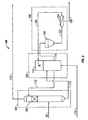
- FIG. 1 is a schematic diagram representing the Claus sulfur recovery step 10 of the inventive process.
- the Claus sulfur recovery step includes a thermal or combustion step 12 and a catalytic step 14.
- An acid gas stream and an oxygen-containing gas stream are introduced into furnace 16, respectively, through lines 18 and 20.
- Furnace 16 provides for the partial combustion of the H 2 S of the acid gas stream to form SO 2 .
- the resulting combustion gas stream passes from furnace 16 through line 22 to heat exchanger 24 whereby it is cooled by the indirect exchange of heat with water.
- the water is supplied to heat exchanger 24 through line 26 and steam passes from heat exchanger 24 through line 28.
- the cooled combustion gas stream from heat exchanger 24 passes to catalytic step 14 of Claus sulfur recovery step 10 through line 30.
- the catalytic step 14 further includes passing the cooled combustion gas stream by way of line 30 to first sulfur condenser 32.
- First sulfur condenser 32 defines a condensation zone and provides means for condensing and separating liquid sulfur from the cooled combustion gas stream to thereby provide a first Claus reactor feed stream that is charged to first Claus reactor 34 by way of line 36.
- the separated liquid sulfur passes from first sulfur condenser 32 by way of line 37.
- Line 36 is in fluid flow communication with first sulfur condenser 32 and first Claus reactor 34 and interposed therein is first reheater 38, which defines a heat exchange zone and provides means for indirectly heating the first Claus reactor feed stream prior to charging it as a feed to first Claus reactor 34.
- steam is a suitable heat source and passes to first reheater 38 through line 40.
- the first Claus reactor 34 defines a reaction zone that contains a catalyst bed 42 of a Claus catalyst, such as activated alumina.
- the first Claus reaction zone defined by first Claus reactor 34 is operated so as to provide for the contacting of the first Claus reactor feed stream with the Claus catalyst contained within the first Claus reaction zone under suitable Claus reaction conditions.
- a first Claus reactor effluent passes from first Claus reactor 34 through line 44 to second sulfur condenser 46.
- Second sulfur condenser 46 defines a condensation zone and provides means for condensing and separating liquid sulfur from the first Claus reactor effluent to thereby provide a second Claus reactor feed stream that is charged to second Claus reactor 48 by way of line 50.
- the separated liquid sulfur passes from second sulfur condenser 46 by way of line 51.
- second reheater 52 Interposed in line 50 is second reheater 52, which defines a heat exchange zone and provides means for indirectly heating the second Claus reactor feed stream prior to charging it as a feed to second Claus reactor 48.
- steam is a suitable heat source and passes to second reheater 52 through line 54.
- the second Claus reactor 48 defines a second Claus reaction zone that contains a catalyst bed 56 of a Claus catalyst, such as activated alumina.
- the second Claus reaction zone defined by second Claus reactor 48 is operated so as to provide for the contacting of the second Claus reactor feed stream with the Claus catalyst contained within the second Claus reaction zone under suitable Claus reaction conditions.
- a second Claus reactor effluent passes from second Claus reactor 48 through line 58 to third sulfur condenser 60.
- Third sulfur condenser 60 defines a condensation zone and provides means for condensing and separating liquid sulfur from the second Claus reactor effluent to thereby provide a Claus tail gas stream that is charged to the biological sulfur recovery step, not shown in FIG. 1 but shown in FIG. 2 , by way of line 62.
- the separated liquid sulfur passes from third sulfur condenser 60 by way of line 64.
- references herein to the Claus process can mean a sulfur recovery process that includes a thermal step followed by a Claus reaction step in which elemental sulfur is formed by way of the Claus reaction as represented by equation (2) above either without the use of a Claus catalyst or with the use of a Claus catalyst and with the Claus reaction step being conducted in one or more reaction stages.
- FIG. 2 is a schematic diagram representing the biological sulfur recovery step 100 of the inventive process.
- the biological sulfur recovery step 100 includes absorption step 102, biological oxidation step 104 and sulfur separation step 106.
- the Claus tail gas stream passing from Claus sulfur recovery step 10 through line 62 is passed to absorption step 102 which provides for the contacting of the Claus tail gas with a lean solvent under suitable absorption conditions to thereby remove H 2 S and even SO 2 , if present, from the Claus tail gas and to yield a sweet tail gas and a rich solvent.
- Providing for the absorption is absorber 108.
- Absorber 108 defines an absorption zone and provides means for the absorption of the H 2 S and SO 2 from the Claus tail gas to yield the sweet tail gas and rich solvent.
- the sweet tail gas passes from absorber 108 through line 110.
- the lean solvent is introduced into absorber 108 by way of line 112, and the Claus tail gas is introduced into absorber 108 by way of line 62.
- the lean solvent and Claus tail gas are contacted together, preferably in a counter-current flow arrangement.
- the rich solvent passes from absorber 108 through line 113 to biological oxidation step 104, which provides for the contacting of the rich solvent and oxygen.
- the sulfur bacteria in the solvent provides for the oxidation of the sulfide dissolved in the rich solvent to elemental sulfur.
- bioreactor 114 Providing for the biological oxidation is bioreactor 114.
- Bioreactor 114 defines a biological oxidation or reaction zone and provides means for the biological oxidation or reaction of the dissolved sulfide contained in the rich solvent to yield the lean solvent.
- Bioreactor 114 provides for the biological oxidation by contacting the rich solvent under suitable bioreaction conditions, with sulfur bacteria and oxygen. Oxygen or air is introduced into bioreactor 114 to be contacted with the rich solvent by way of line 115.
- Lean solvent passes from bioreactor 114 and is charged, as noted above, as a feed to absorber 108 through line 112 while a portion of the lean solvent from bioreactor 114 passes through line 118 to sulfur separation step 106.
- Sulfur separation step 106 provides for the removal of sulfur from the lean solvent to yield a bioreaction sulfur product and a sulfur reduced lean solvent.
- the separation step 106 includes the passing of the portion of lean solvent to sulfur settling vessel 120.
- Settling vessel 120 defines a settling zone that provides for a residence time for the lean solvent thereby allowing for the settling of the sulfur particles therein.
- a slurry comprising sulfur particles is removed from settling vessel 120 and passes therefrom through line 122 to a sulfur separation means 124, such as, for example, a centrifuge or a decanter.
- Sulfur separation means 124 defines a separation zone and provides means for separating sulfur from the slurry to yield the bioreactor sulfur product and the sulfur reduced lean solvent.
- the bioreactor sulfur product passes from sulfur separation means 124 through line 126.
- the sulfur reduced lean solvent is recycled to bioreactor 114 through line 128.
- This Example presents a typical acid gas feed composition that is charged to a typical two-stage Claus sulfur plant and the calculated tail gas compositions for a base case representing the standard operation of the Claus sulfur plant, i.e. a Claus reactor feed H 2 S to SO 2 molar ratio of 2:1, and an inventive case representing the method of operation of the Claus sulfur plant of the inventive process.
- a base case representing the standard operation of the Claus sulfur plant, i.e. a Claus reactor feed H 2 S to SO 2 molar ratio of 2:1
- an inventive case representing the method of operation of the Claus sulfur plant of the inventive process.
- Table 3 Presented in Table 3 below is a typical Claus sulfur plant acid gas feed stream, the calculated tail gas composition of the Claus sulfur plant when it is operated to obtain the typical 2:1 molar ratio H 2 S to SO 2 in the tail gas, and the calculated tail gas composition of the Claus sulfur plant when it is operated by reducing combustion air input to the Claus sulfur plant so as to obtain a 20:1 molar ratio H 2 S to SO 2 in the tail gas.
- Table 3 Presented in Table 3 below is a typical Claus sulfur plant acid gas feed stream, the calculated tail gas composition of the Claus sulfur plant when it is operated to obtain the typical 2:1 molar ratio H 2 S to SO 2 in the tail gas, and the calculated tail gas composition of the Claus sulfur plant when it is operated by reducing combustion air input to the Claus sulfur plant so as to obtain a 20:1 molar ratio H 2 S to SO 2 in the tail gas.
Landscapes
- Engineering & Computer Science (AREA)
- Chemical & Material Sciences (AREA)
- Environmental & Geological Engineering (AREA)
- Biomedical Technology (AREA)
- Health & Medical Sciences (AREA)
- Analytical Chemistry (AREA)
- General Chemical & Material Sciences (AREA)
- Oil, Petroleum & Natural Gas (AREA)
- Chemical Kinetics & Catalysis (AREA)
- Organic Chemistry (AREA)
- Molecular Biology (AREA)
- Life Sciences & Earth Sciences (AREA)
- Inorganic Chemistry (AREA)
- Treating Waste Gases (AREA)
- Purification Treatments By Anaerobic Or Anaerobic And Aerobic Bacteria Or Animals (AREA)
Priority Applications (1)
| Application Number | Priority Date | Filing Date | Title |
|---|---|---|---|
| PL05724270T PL1720635T3 (pl) | 2004-03-03 | 2005-03-02 | Sposób odzyskiwania siarki ze strumienia kwaśnego gazu z wysoką wydajnością |
Applications Claiming Priority (2)
| Application Number | Priority Date | Filing Date | Title |
|---|---|---|---|
| US54968504P | 2004-03-03 | 2004-03-03 | |
| PCT/US2005/006690 WO2005092479A1 (en) | 2004-03-03 | 2005-03-02 | A process for the high recovery efficiency of sulfur from an acid gas stream |
Publications (2)
| Publication Number | Publication Date |
|---|---|
| EP1720635A1 EP1720635A1 (en) | 2006-11-15 |
| EP1720635B1 true EP1720635B1 (en) | 2013-09-04 |
Family
ID=34962220
Family Applications (1)
| Application Number | Title | Priority Date | Filing Date |
|---|---|---|---|
| EP05724270.3A Not-in-force EP1720635B1 (en) | 2004-03-03 | 2005-03-02 | A process for the high recovery efficiency of sulfur from an acid gas stream |
Country Status (13)
| Country | Link |
|---|---|
| US (1) | US7351392B2 (ja) |
| EP (1) | EP1720635B1 (ja) |
| JP (1) | JP4847950B2 (ja) |
| KR (1) | KR101155844B1 (ja) |
| CN (1) | CN100553746C (ja) |
| AU (1) | AU2005225420B2 (ja) |
| BR (1) | BRPI0508284A (ja) |
| CA (1) | CA2558234C (ja) |
| NO (1) | NO20064457L (ja) |
| PL (1) | PL1720635T3 (ja) |
| RU (1) | RU2388524C2 (ja) |
| WO (1) | WO2005092479A1 (ja) |
| ZA (1) | ZA200607338B (ja) |
Cited By (1)
| Publication number | Priority date | Publication date | Assignee | Title |
|---|---|---|---|---|
| CN109908717A (zh) * | 2019-03-26 | 2019-06-21 | 四川大学 | 气体循环式生物鼓泡塔沼气/天然气生物脱硫方法 |
Families Citing this family (26)
| Publication number | Priority date | Publication date | Assignee | Title |
|---|---|---|---|---|
| RU2383385C2 (ru) * | 2004-03-03 | 2010-03-10 | Шелл Интернэшнл Рисерч Маатсхаппий Б.В. | Способ высокоэффективного извлечения серы из потока кислого газа |
| TW200940158A (en) * | 2008-03-07 | 2009-10-01 | Taiheiyo Cement Corp | Cement kiln extracted gas treating system and treating method |
| US8524184B2 (en) * | 2009-07-08 | 2013-09-03 | Exxonmobil Research And Engineering Company | Sulfur recovery plant tail gas treatment process |
| US7951353B1 (en) * | 2010-06-07 | 2011-05-31 | Merichem Company | Flow control method and apparatus for a continuous multiple zone mass transfer |
| CN103480252A (zh) * | 2012-06-13 | 2014-01-01 | 中国石油天然气股份有限公司 | 一种含硫化氢的酸性气体处理方法 |
| US9370745B2 (en) | 2013-04-24 | 2016-06-21 | Jiangsu New Century Jiangnan Environmental Protection Co., Ltd | Flue gas-treating method and apparatus for treating acidic tail gas by using ammonia process |
| CA2927394C (en) * | 2013-11-08 | 2019-08-20 | Saudi Arabian Oil Company | Sulfur recovery unit and process |
| CN105293443B (zh) * | 2014-06-06 | 2018-03-20 | 中国石油化工股份有限公司 | 降低硫磺装置烟气so2排放浓度的方法 |
| CN104475104B (zh) * | 2014-11-05 | 2018-03-23 | 杨楠 | 选择性催化氧化硫化氢催化剂、尾气焚烧催化剂及深度催化氧化硫化氢为硫磺的工艺 |
| CN107970735A (zh) * | 2016-10-21 | 2018-05-01 | 中国石油化工股份有限公司 | 再生脱硫吸附剂产生的尾气的处理方法和脱硫吸附剂再生的方法 |
| CN108144428A (zh) | 2017-03-15 | 2018-06-12 | 江苏新世纪江南环保股份有限公司 | 一种氨法高效脱除气体中硫氧化物和尘的方法及装置 |
| CN107213785B (zh) | 2017-05-25 | 2020-08-07 | 江苏新世纪江南环保股份有限公司 | 一种fcc尾气氨法脱硝脱硫除尘的方法及装置 |
| CN107213769B (zh) | 2017-05-25 | 2019-09-20 | 江苏新世纪江南环保股份有限公司 | 一种分室加氨的氨法脱硫方法及装置 |
| EP3415222A1 (en) | 2017-06-14 | 2018-12-19 | Jiangnan Environmental Protection Group Inc. | Automatic ammonia-adding system and method for ammonia-based desulfurization device |
| CN107213770B (zh) | 2017-07-03 | 2023-03-17 | 江苏新世纪江南环保股份有限公司 | 氨法脱硫吸收塔及其建立方法和运行方法 |
| CN108722163B (zh) | 2017-09-07 | 2019-06-07 | 江苏新世纪江南环保股份有限公司 | 一种氨法脱硫控制吸收过程气溶胶产生的方法 |
| US10246329B1 (en) * | 2017-11-17 | 2019-04-02 | Saudi Arabian Oil Company | Extended thermal stage sulfur recovery process |
| CN116510513A (zh) | 2018-04-13 | 2023-08-01 | 江苏新世纪江南环保股份有限公司 | 氨法脱硫溶液的氧化方法及装置 |
| CN108588418B (zh) * | 2018-06-07 | 2019-07-26 | 江西理工大学 | 钨酸盐溶液中负二价硫回收利用的装置和方法 |
| CN110732227B (zh) | 2018-07-20 | 2023-02-21 | 江南环保集团股份有限公司 | 一种酸性气处理的方法和装置 |
| CN109179339B (zh) * | 2018-08-30 | 2020-10-23 | 山东迅达化工集团有限公司 | 中低浓度酸性气的硫磺回收工艺 |
| CN111957183A (zh) | 2019-12-26 | 2020-11-20 | 江苏新世纪江南环保股份有限公司 | 一种改进的氨法脱硫控制吸收过程气溶胶产生的方法 |
| CN113264508B (zh) * | 2020-02-17 | 2022-08-05 | 中国石油天然气集团有限公司 | 硫磺回收方法及装置 |
| CN111389202A (zh) * | 2020-04-21 | 2020-07-10 | 福建龙净脱硫脱硝工程有限公司 | 一种干法脱硫系统和一种干法脱硫方法 |
| CN115990392B (zh) * | 2021-10-19 | 2024-08-30 | 中国石油化工股份有限公司 | 一种烟气脱硫和硫磺回收的耦合工艺及其装置 |
| CN114958687B (zh) * | 2022-06-24 | 2023-06-02 | 广州金鹏环保工程有限公司 | 一种耐碱的史蒂文斯盐单胞菌及其在处理硫化氢废气中的应用 |
Family Cites Families (21)
| Publication number | Priority date | Publication date | Assignee | Title |
|---|---|---|---|---|
| US3985861A (en) * | 1974-09-16 | 1976-10-12 | Shell Oil Company | Process for removing sulfur compounds from claus off-gases |
| DE2923704A1 (de) * | 1979-06-12 | 1980-12-18 | Bergwerksverband Gmbh | Verfahren zur reduktion von so tief 2 -reichgasen zu elementarem schwefel |
| JPS5782107A (en) * | 1980-11-05 | 1982-05-22 | Sumitomo Heavy Ind Ltd | Recovery of sulfur from so2-containing gas |
| EP0084410A3 (en) | 1982-01-19 | 1983-08-03 | Imperial Chemical Industries Plc | The removal of hydrogen sulphide from gas streams |
| US4760027A (en) | 1986-04-09 | 1988-07-26 | Combustion Engineering, Inc. | Microbiological desulfurization of gases |
| NL9002661A (nl) * | 1990-12-04 | 1992-07-01 | Pacques Bv | Werkwijze voor de verwijdering van h2s uit gas. |
| ZA93401B (en) * | 1992-01-27 | 1993-08-24 | Phillips Petroleum Co | Composition useful as sulfur absorption for fluid streams. |
| AU666522B2 (en) * | 1992-04-06 | 1996-02-15 | Boc Group Plc, The | Treatment of gas streams |
| US5965100A (en) * | 1995-04-25 | 1999-10-12 | Khanmamedov; Tofik K. | Process for recovery of sulfur from an acid gas stream |
| AU713082B2 (en) | 1996-05-10 | 1999-11-25 | Paques Ipt B.V. | Process for the purification of gases containing hydrogen sulphide |
| EP0845288A1 (en) * | 1996-11-27 | 1998-06-03 | Thiopaq Sulfur Systems B.V. | Process for biological removal of sulphide |
| NL1006339C2 (nl) * | 1997-06-17 | 1998-12-21 | Stork Eng & Contractors Bv | Werkwijze voor het ontzwavelen van afgassen. |
| US6297189B1 (en) * | 1998-01-14 | 2001-10-02 | The Regents Of The University Of California | Sulfide catalysts for reducing SO2 to elemental sulfur |
| US6056934A (en) * | 1998-05-08 | 2000-05-02 | Midamerican Energy Holdings Co. | Method and device for hydrogen sulfide abatement and production of sulfuric acid |
| PT1115472E (pt) * | 1998-08-25 | 2003-12-31 | Gastec Nv | Processo para a recuperacao de enxofre de um gas contendo sulfureto de hidrogenio |
| NL1011490C2 (nl) * | 1999-03-08 | 2000-09-12 | Paques Bio Syst Bv | Werkwijze voor het ontzwavelen van gassen. |
| GB9930562D0 (en) * | 1999-12-23 | 2000-02-16 | Boc Group Plc | Partial oxidation of hydrogen sulphide |
| US20010034056A1 (en) * | 2000-03-03 | 2001-10-25 | Corey Kenneth J. | Odor control scrubber |
| CA2342136A1 (en) * | 2000-04-05 | 2001-10-05 | Vijay Ramanand Balse | Treatment of gas streams containing hydrogen sulphide |
| US6696284B2 (en) * | 2001-10-23 | 2004-02-24 | Council Of Scientific And Industrial Research | Biological filter for the purification of waste gases |
| RU2383385C2 (ru) * | 2004-03-03 | 2010-03-10 | Шелл Интернэшнл Рисерч Маатсхаппий Б.В. | Способ высокоэффективного извлечения серы из потока кислого газа |
-
2005
- 2005-03-02 US US11/070,117 patent/US7351392B2/en not_active Expired - Fee Related
- 2005-03-02 AU AU2005225420A patent/AU2005225420B2/en not_active Ceased
- 2005-03-02 BR BRPI0508284-6A patent/BRPI0508284A/pt not_active IP Right Cessation
- 2005-03-02 RU RU2006134727/15A patent/RU2388524C2/ru not_active IP Right Cessation
- 2005-03-02 WO PCT/US2005/006690 patent/WO2005092479A1/en active Search and Examination
- 2005-03-02 JP JP2007501920A patent/JP4847950B2/ja not_active Expired - Fee Related
- 2005-03-02 KR KR1020067020258A patent/KR101155844B1/ko not_active IP Right Cessation
- 2005-03-02 EP EP05724270.3A patent/EP1720635B1/en not_active Not-in-force
- 2005-03-02 CN CNB2005800110941A patent/CN100553746C/zh not_active Expired - Fee Related
- 2005-03-02 PL PL05724270T patent/PL1720635T3/pl unknown
- 2005-03-02 CA CA2558234A patent/CA2558234C/en not_active Expired - Fee Related
-
2006
- 2006-09-01 ZA ZA2006/07338A patent/ZA200607338B/en unknown
- 2006-10-02 NO NO20064457A patent/NO20064457L/no not_active Application Discontinuation
Cited By (2)
| Publication number | Priority date | Publication date | Assignee | Title |
|---|---|---|---|---|
| CN109908717A (zh) * | 2019-03-26 | 2019-06-21 | 四川大学 | 气体循环式生物鼓泡塔沼气/天然气生物脱硫方法 |
| CN109908717B (zh) * | 2019-03-26 | 2021-09-24 | 四川大学 | 气体循环式生物鼓泡塔沼气/天然气生物脱硫方法 |
Also Published As
| Publication number | Publication date |
|---|---|
| CA2558234C (en) | 2013-08-20 |
| CA2558234A1 (en) | 2005-10-06 |
| AU2005225420B2 (en) | 2008-11-06 |
| ZA200607338B (en) | 2008-04-30 |
| KR101155844B1 (ko) | 2012-06-21 |
| RU2006134727A (ru) | 2008-04-10 |
| EP1720635A1 (en) | 2006-11-15 |
| CN1964773A (zh) | 2007-05-16 |
| US7351392B2 (en) | 2008-04-01 |
| PL1720635T3 (pl) | 2014-04-30 |
| US20050196338A1 (en) | 2005-09-08 |
| JP2007526871A (ja) | 2007-09-20 |
| WO2005092479A1 (en) | 2005-10-06 |
| BRPI0508284A (pt) | 2007-08-07 |
| CN100553746C (zh) | 2009-10-28 |
| RU2388524C2 (ru) | 2010-05-10 |
| KR20070011345A (ko) | 2007-01-24 |
| JP4847950B2 (ja) | 2011-12-28 |
| AU2005225420A1 (en) | 2005-10-06 |
| NO20064457L (no) | 2006-10-02 |
Similar Documents
| Publication | Publication Date | Title |
|---|---|---|
| EP1720635B1 (en) | A process for the high recovery efficiency of sulfur from an acid gas stream | |
| US7754471B2 (en) | Process for the high recovery efficiency of sulfur from an acid gas stream | |
| EP1628744B1 (en) | A process for the removal of so2, hcn and h2s and optionally cos, cs2 and nh3 from a gas stream | |
| EP0212297A2 (en) | High pressure process for sulfur recovery from a hydrogen sulfide containing gas stream | |
| AU2009312761B2 (en) | Method and apparatus for treating an off-gas stream | |
| CA2823228A1 (en) | Process for removing sulphur-containing contaminants from a gas stream | |
| US8557206B2 (en) | Configurations and methods for effluent gas treatment | |
| AU2002331591B2 (en) | Configurations and methods for effluent gas treatment | |
| US20080233025A1 (en) | Method and system for recovering sulphur from gas streams | |
| US8709366B2 (en) | Configurations and methods for effluent gas treatment | |
| EP0568980A1 (en) | Combustion of H2S and its associated Claus process |
Legal Events
| Date | Code | Title | Description |
|---|---|---|---|
| PUAI | Public reference made under article 153(3) epc to a published international application that has entered the european phase |
Free format text: ORIGINAL CODE: 0009012 |
|
| 17P | Request for examination filed |
Effective date: 20060825 |
|
| AK | Designated contracting states |
Kind code of ref document: A1 Designated state(s): AT BE BG CH CY CZ DE DK EE ES FI FR GB GR HU IE IS IT LI LT LU MC NL PL PT RO SE SI SK TR |
|
| DAX | Request for extension of the european patent (deleted) | ||
| 17Q | First examination report despatched |
Effective date: 20100730 |
|
| GRAP | Despatch of communication of intention to grant a patent |
Free format text: ORIGINAL CODE: EPIDOSNIGR1 |
|
| INTG | Intention to grant announced |
Effective date: 20130326 |
|
| GRAS | Grant fee paid |
Free format text: ORIGINAL CODE: EPIDOSNIGR3 |
|
| GRAA | (expected) grant |
Free format text: ORIGINAL CODE: 0009210 |
|
| AK | Designated contracting states |
Kind code of ref document: B1 Designated state(s): AT BE BG CH CY CZ DE DK EE ES FI FR GB GR HU IE IS IT LI LT LU MC NL PL PT RO SE SI SK TR |
|
| REG | Reference to a national code |
Ref country code: GB Ref legal event code: FG4D |
|
| REG | Reference to a national code |
Ref country code: CH Ref legal event code: EP |
|
| REG | Reference to a national code |
Ref country code: AT Ref legal event code: REF Ref document number: 630169 Country of ref document: AT Kind code of ref document: T Effective date: 20130915 |
|
| REG | Reference to a national code |
Ref country code: IE Ref legal event code: FG4D |
|
| REG | Reference to a national code |
Ref country code: DE Ref legal event code: R096 Ref document number: 602005041112 Country of ref document: DE Effective date: 20131024 |
|
| REG | Reference to a national code |
Ref country code: AT Ref legal event code: MK05 Ref document number: 630169 Country of ref document: AT Kind code of ref document: T Effective date: 20130904 |
|
| REG | Reference to a national code |
Ref country code: NL Ref legal event code: VDEP Effective date: 20130904 |
|
| PG25 | Lapsed in a contracting state [announced via postgrant information from national office to epo] |
Ref country code: CY Free format text: LAPSE BECAUSE OF FAILURE TO SUBMIT A TRANSLATION OF THE DESCRIPTION OR TO PAY THE FEE WITHIN THE PRESCRIBED TIME-LIMIT Effective date: 20130710 Ref country code: LT Free format text: LAPSE BECAUSE OF FAILURE TO SUBMIT A TRANSLATION OF THE DESCRIPTION OR TO PAY THE FEE WITHIN THE PRESCRIBED TIME-LIMIT Effective date: 20130904 Ref country code: AT Free format text: LAPSE BECAUSE OF FAILURE TO SUBMIT A TRANSLATION OF THE DESCRIPTION OR TO PAY THE FEE WITHIN THE PRESCRIBED TIME-LIMIT Effective date: 20130904 Ref country code: SE Free format text: LAPSE BECAUSE OF FAILURE TO SUBMIT A TRANSLATION OF THE DESCRIPTION OR TO PAY THE FEE WITHIN THE PRESCRIBED TIME-LIMIT Effective date: 20130904 |
|
| REG | Reference to a national code |
Ref country code: NL Ref legal event code: VDEP Effective date: 20130904 |
|
| REG | Reference to a national code |
Ref country code: LT Ref legal event code: MG4D |
|
| PG25 | Lapsed in a contracting state [announced via postgrant information from national office to epo] |
Ref country code: GR Free format text: LAPSE BECAUSE OF FAILURE TO SUBMIT A TRANSLATION OF THE DESCRIPTION OR TO PAY THE FEE WITHIN THE PRESCRIBED TIME-LIMIT Effective date: 20131205 Ref country code: SI Free format text: LAPSE BECAUSE OF FAILURE TO SUBMIT A TRANSLATION OF THE DESCRIPTION OR TO PAY THE FEE WITHIN THE PRESCRIBED TIME-LIMIT Effective date: 20130904 Ref country code: FI Free format text: LAPSE BECAUSE OF FAILURE TO SUBMIT A TRANSLATION OF THE DESCRIPTION OR TO PAY THE FEE WITHIN THE PRESCRIBED TIME-LIMIT Effective date: 20130904 Ref country code: ES Free format text: LAPSE BECAUSE OF FAILURE TO SUBMIT A TRANSLATION OF THE DESCRIPTION OR TO PAY THE FEE WITHIN THE PRESCRIBED TIME-LIMIT Effective date: 20130904 |
|
| PG25 | Lapsed in a contracting state [announced via postgrant information from national office to epo] |
Ref country code: BE Free format text: LAPSE BECAUSE OF FAILURE TO SUBMIT A TRANSLATION OF THE DESCRIPTION OR TO PAY THE FEE WITHIN THE PRESCRIBED TIME-LIMIT Effective date: 20130904 Ref country code: CY Free format text: LAPSE BECAUSE OF FAILURE TO SUBMIT A TRANSLATION OF THE DESCRIPTION OR TO PAY THE FEE WITHIN THE PRESCRIBED TIME-LIMIT Effective date: 20130904 |
|
| PG25 | Lapsed in a contracting state [announced via postgrant information from national office to epo] |
Ref country code: NL Free format text: LAPSE BECAUSE OF FAILURE TO SUBMIT A TRANSLATION OF THE DESCRIPTION OR TO PAY THE FEE WITHIN THE PRESCRIBED TIME-LIMIT Effective date: 20130904 Ref country code: EE Free format text: LAPSE BECAUSE OF FAILURE TO SUBMIT A TRANSLATION OF THE DESCRIPTION OR TO PAY THE FEE WITHIN THE PRESCRIBED TIME-LIMIT Effective date: 20130904 Ref country code: RO Free format text: LAPSE BECAUSE OF FAILURE TO SUBMIT A TRANSLATION OF THE DESCRIPTION OR TO PAY THE FEE WITHIN THE PRESCRIBED TIME-LIMIT Effective date: 20130904 Ref country code: SK Free format text: LAPSE BECAUSE OF FAILURE TO SUBMIT A TRANSLATION OF THE DESCRIPTION OR TO PAY THE FEE WITHIN THE PRESCRIBED TIME-LIMIT Effective date: 20130904 Ref country code: IS Free format text: LAPSE BECAUSE OF FAILURE TO SUBMIT A TRANSLATION OF THE DESCRIPTION OR TO PAY THE FEE WITHIN THE PRESCRIBED TIME-LIMIT Effective date: 20140104 Ref country code: CZ Free format text: LAPSE BECAUSE OF FAILURE TO SUBMIT A TRANSLATION OF THE DESCRIPTION OR TO PAY THE FEE WITHIN THE PRESCRIBED TIME-LIMIT Effective date: 20130904 |
|
| REG | Reference to a national code |
Ref country code: PL Ref legal event code: T3 |
|
| REG | Reference to a national code |
Ref country code: DE Ref legal event code: R097 Ref document number: 602005041112 Country of ref document: DE |
|
| PG25 | Lapsed in a contracting state [announced via postgrant information from national office to epo] |
Ref country code: PT Free format text: LAPSE BECAUSE OF FAILURE TO SUBMIT A TRANSLATION OF THE DESCRIPTION OR TO PAY THE FEE WITHIN THE PRESCRIBED TIME-LIMIT Effective date: 20140106 |
|
| PLBE | No opposition filed within time limit |
Free format text: ORIGINAL CODE: 0009261 |
|
| STAA | Information on the status of an ep patent application or granted ep patent |
Free format text: STATUS: NO OPPOSITION FILED WITHIN TIME LIMIT |
|
| 26N | No opposition filed |
Effective date: 20140605 |
|
| REG | Reference to a national code |
Ref country code: DE Ref legal event code: R097 Ref document number: 602005041112 Country of ref document: DE Effective date: 20140605 |
|
| PG25 | Lapsed in a contracting state [announced via postgrant information from national office to epo] |
Ref country code: DK Free format text: LAPSE BECAUSE OF FAILURE TO SUBMIT A TRANSLATION OF THE DESCRIPTION OR TO PAY THE FEE WITHIN THE PRESCRIBED TIME-LIMIT Effective date: 20130904 |
|
| PG25 | Lapsed in a contracting state [announced via postgrant information from national office to epo] |
Ref country code: LU Free format text: LAPSE BECAUSE OF FAILURE TO SUBMIT A TRANSLATION OF THE DESCRIPTION OR TO PAY THE FEE WITHIN THE PRESCRIBED TIME-LIMIT Effective date: 20140302 |
|
| REG | Reference to a national code |
Ref country code: CH Ref legal event code: PL |
|
| GBPC | Gb: european patent ceased through non-payment of renewal fee |
Effective date: 20140302 |
|
| REG | Reference to a national code |
Ref country code: IE Ref legal event code: MM4A |
|
| PG25 | Lapsed in a contracting state [announced via postgrant information from national office to epo] |
Ref country code: LI Free format text: LAPSE BECAUSE OF NON-PAYMENT OF DUE FEES Effective date: 20140331 Ref country code: CH Free format text: LAPSE BECAUSE OF NON-PAYMENT OF DUE FEES Effective date: 20140331 Ref country code: IE Free format text: LAPSE BECAUSE OF NON-PAYMENT OF DUE FEES Effective date: 20140302 Ref country code: GB Free format text: LAPSE BECAUSE OF NON-PAYMENT OF DUE FEES Effective date: 20140302 |
|
| REG | Reference to a national code |
Ref country code: FR Ref legal event code: PLFP Year of fee payment: 11 |
|
| PGFP | Annual fee paid to national office [announced via postgrant information from national office to epo] |
Ref country code: IT Payment date: 20150224 Year of fee payment: 11 Ref country code: DE Payment date: 20150224 Year of fee payment: 11 |
|
| PGFP | Annual fee paid to national office [announced via postgrant information from national office to epo] |
Ref country code: PL Payment date: 20150114 Year of fee payment: 11 Ref country code: FR Payment date: 20150309 Year of fee payment: 11 |
|
| PG25 | Lapsed in a contracting state [announced via postgrant information from national office to epo] |
Ref country code: BG Free format text: LAPSE BECAUSE OF FAILURE TO SUBMIT A TRANSLATION OF THE DESCRIPTION OR TO PAY THE FEE WITHIN THE PRESCRIBED TIME-LIMIT Effective date: 20130904 Ref country code: MC Free format text: LAPSE BECAUSE OF FAILURE TO SUBMIT A TRANSLATION OF THE DESCRIPTION OR TO PAY THE FEE WITHIN THE PRESCRIBED TIME-LIMIT Effective date: 20130904 |
|
| PG25 | Lapsed in a contracting state [announced via postgrant information from national office to epo] |
Ref country code: TR Free format text: LAPSE BECAUSE OF FAILURE TO SUBMIT A TRANSLATION OF THE DESCRIPTION OR TO PAY THE FEE WITHIN THE PRESCRIBED TIME-LIMIT Effective date: 20130904 Ref country code: HU Free format text: LAPSE BECAUSE OF FAILURE TO SUBMIT A TRANSLATION OF THE DESCRIPTION OR TO PAY THE FEE WITHIN THE PRESCRIBED TIME-LIMIT; INVALID AB INITIO Effective date: 20050302 |
|
| REG | Reference to a national code |
Ref country code: DE Ref legal event code: R119 Ref document number: 602005041112 Country of ref document: DE |
|
| REG | Reference to a national code |
Ref country code: FR Ref legal event code: ST Effective date: 20161130 |
|
| PG25 | Lapsed in a contracting state [announced via postgrant information from national office to epo] |
Ref country code: DE Free format text: LAPSE BECAUSE OF NON-PAYMENT OF DUE FEES Effective date: 20161001 Ref country code: FR Free format text: LAPSE BECAUSE OF NON-PAYMENT OF DUE FEES Effective date: 20160331 |
|
| PG25 | Lapsed in a contracting state [announced via postgrant information from national office to epo] |
Ref country code: IT Free format text: LAPSE BECAUSE OF NON-PAYMENT OF DUE FEES Effective date: 20160302 |
|
| PG25 | Lapsed in a contracting state [announced via postgrant information from national office to epo] |
Ref country code: PL Free format text: LAPSE BECAUSE OF NON-PAYMENT OF DUE FEES Effective date: 20160302 |