EP1720472B1 - Element de liaison dynamique pour un systeme de fixation rachidien et systeme de fixation comprenant un tel element de liaison - Google Patents
Element de liaison dynamique pour un systeme de fixation rachidien et systeme de fixation comprenant un tel element de liaison Download PDFInfo
- Publication number
- EP1720472B1 EP1720472B1 EP05732859A EP05732859A EP1720472B1 EP 1720472 B1 EP1720472 B1 EP 1720472B1 EP 05732859 A EP05732859 A EP 05732859A EP 05732859 A EP05732859 A EP 05732859A EP 1720472 B1 EP1720472 B1 EP 1720472B1
- Authority
- EP
- European Patent Office
- Prior art keywords
- linking element
- strands
- cable
- layer
- strand
- Prior art date
- Legal status (The legal status is an assumption and is not a legal conclusion. Google has not performed a legal analysis and makes no representation as to the accuracy of the status listed.)
- Expired - Lifetime
Links
Images

Classifications
-
- A—HUMAN NECESSITIES
- A61—MEDICAL OR VETERINARY SCIENCE; HYGIENE
- A61F—FILTERS IMPLANTABLE INTO BLOOD VESSELS; PROSTHESES; DEVICES PROVIDING PATENCY TO, OR PREVENTING COLLAPSING OF, TUBULAR STRUCTURES OF THE BODY, e.g. STENTS; ORTHOPAEDIC, NURSING OR CONTRACEPTIVE DEVICES; FOMENTATION; TREATMENT OR PROTECTION OF EYES OR EARS; BANDAGES, DRESSINGS OR ABSORBENT PADS; FIRST-AID KITS
- A61F2/00—Filters implantable into blood vessels; Prostheses, i.e. artificial substitutes or replacements for parts of the body; Appliances for connecting them with the body; Devices providing patency to, or preventing collapsing of, tubular structures of the body, e.g. stents
- A61F2/02—Prostheses implantable into the body
- A61F2/30—Joints
- A61F2/44—Joints for the spine, e.g. vertebrae, spinal discs
-
- A—HUMAN NECESSITIES
- A61—MEDICAL OR VETERINARY SCIENCE; HYGIENE
- A61B—DIAGNOSIS; SURGERY; IDENTIFICATION
- A61B17/00—Surgical instruments, devices or methods
- A61B17/56—Surgical instruments or methods for treatment of bones or joints; Devices specially adapted therefor
- A61B17/58—Surgical instruments or methods for treatment of bones or joints; Devices specially adapted therefor for osteosynthesis, e.g. bone plates, screws or setting implements
- A61B17/68—Internal fixation devices, including fasteners and spinal fixators, even if a part thereof projects from the skin
- A61B17/70—Spinal positioners or stabilisers, e.g. stabilisers comprising fluid filler in an implant
- A61B17/7001—Screws or hooks combined with longitudinal elements which do not contact vertebrae
- A61B17/7002—Longitudinal elements, e.g. rods
- A61B17/7019—Longitudinal elements having flexible parts, or parts connected together, such that after implantation the elements can move relative to each other
- A61B17/7022—Tethers, i.e. longitudinal elements capable of transmitting tension only, e.g. straps, sutures or cables
-
- A—HUMAN NECESSITIES
- A61—MEDICAL OR VETERINARY SCIENCE; HYGIENE
- A61B—DIAGNOSIS; SURGERY; IDENTIFICATION
- A61B17/00—Surgical instruments, devices or methods
- A61B17/56—Surgical instruments or methods for treatment of bones or joints; Devices specially adapted therefor
- A61B17/58—Surgical instruments or methods for treatment of bones or joints; Devices specially adapted therefor for osteosynthesis, e.g. bone plates, screws or setting implements
- A61B17/68—Internal fixation devices, including fasteners and spinal fixators, even if a part thereof projects from the skin
- A61B17/70—Spinal positioners or stabilisers, e.g. stabilisers comprising fluid filler in an implant
- A61B17/7001—Screws or hooks combined with longitudinal elements which do not contact vertebrae
- A61B17/7002—Longitudinal elements, e.g. rods
- A61B17/7019—Longitudinal elements having flexible parts, or parts connected together, such that after implantation the elements can move relative to each other
- A61B17/7031—Longitudinal elements having flexible parts, or parts connected together, such that after implantation the elements can move relative to each other made wholly or partly of flexible material
Definitions
- the present invention relates to the field of spinal fixation systems for the connection of vertebrae to each other, and more particularly to the field of connecting elements intended to maintain a spacing between at least two anchoring elements respectively implanted in a vertebra.
- Spinal osteosynthesis bonds are well known bonds. They are indeed commonly used to consolidate several consecutive vertebrae. They aim to freeze the vertebrae in a particular configuration and stabilize them during bone fusion to allow a fixed stabilization in the frozen situation. Such bonds consist of rigid rods.
- the dynamic links are used to reduce the constraints on the articular facets and on the intervertebral discs by allowing certain movements, while realigning, if necessary, the vertebrae with respect to each other.
- Said device comprises a connecting element consisting of a strip made of elastic synthetic material and having a round cross section.
- This band is intended to be fixed between at least two pedicle screws each consisting of a head provided with a transverse bore. Fixing said band on said pedicle screws is performed by inserting through said transverse bore said band, which is then fixed on each of said pedicle screws by means of a clamping screw arranged along the axis of the corresponding screw, or transversely at the piercing.
- Said device further comprises a support element mounted around said band to form a pressure-resistant body.
- Such a connecting element has the disadvantage of not making any torsional return in order to oppose pivoting movements of the vertebrae around the disks.
- the connecting element occupies a large volume (of the order of 12.5 millimeters). In some circumstances, it may be difficult to prevent the connecting element in question from coming into contact with bones, such contact causing severe pain.
- such a device has a particularly important drawback related to the fact of the need to choose the length of the support element before the establishment of said strip.
- the effective distance between the screws after tensioning the strip is not exactly that desired.
- the device as configured does not allow any freedom of distraction and / or compression between the screws after the introduction of the strip and the support element. The surgeon therefore has no choice but to disassemble the entire support element and strip for introducing a new bearing element having a different length.
- a connecting piece intended to maintain a spacing between at least two anchoring elements screwed into vertebrae, said connecting piece comprising: i) a flexible part divided into two continuous branches spaced apart from one another, said branches being substantially symmetrical with respect to the longitudinal axis of said part, the ends of said branches being connected together in pairs and defining a first middle plane, and ii) two rigid parts forming rods, having a first fixing portion and a second portion, each said second portion of said two rigid portions respectively extending in opposite directions said ends of said branches connected together in pairs, the cross section of each of said branches being smaller than the cross section of said rigid portions so that said connecting piece , whose said fixing portions are respectively fixed on each of the two anchoring elements, being able to flex elastically perpendicular to said average plane during the relative movement of the vertebrae, whereby the vertebrae, kept spaced apart from each other, are movable relative to each other .
- This connecting piece however has the disadvantage of being able to flex only in a specific direction, namely in the perpendicular to the average plane that forms the two branches. It follows a mounting of the entire stabilization system comprising such connecting pieces requiring some precision and therefore can be tedious.
- Another disadvantage of such a connecting piece is also its volume.
- the patent application US5704936 being the state of the art closest to the invention, describes a connecting element for a spinal fixation system, intended to bind at least two implantable connection sets.
- the connecting element is constituted by a rod comprising a flexible part comprising a cable which consists of at least one elastic strand.
- a first object of the invention is to overcome the disadvantages of the dynamic link elements described above by proposing a connecting element having an equivalent bending amplitude with respect to these dynamic connecting elements, but the maintenance of rotation is ensured.
- Said connecting element which is the subject of the invention also has the advantage of being able to be bent so as to adapt to the natural lordosis of the lumbar spine.
- Said connecting element object of the invention also has the advantage of being non-invasive, while ensuring the functionality required for a dynamic link element (flexibility, wear resistance, ).
- Said connecting element also has the advantage of allowing quick mounting on the anchoring elements attached to the vertebrae.
- the linking element has the advantage of being able to undergo distraction and / or compression after it has been placed on the anchoring elements.
- the present invention relates to a connecting element for a spinal fixation system, intended to link at least two implantable connection assemblies, said connecting element being remarkable in that it consists of a cable and a a polymer jacket surrounding said cable, said cable consisting of at least one elastic strand coaxial with said envelope so as to form the core of the connecting element.
- said strand forming the core of said connecting element is defined as a central strand.
- said connecting element comprises at least one layer of at least 6 strands distributed around said central strand.
- said connecting element comprises two layers of strands successive layers disposed around said central strand, the first layer of strands surrounding said central strand being constituted by 6 strands, the second strand layer surrounding said first layer consisting of 12 strands.
- the strands constituting the layer (or layers) consist of strands twisted around said central strand.
- the strands of the (or) layer (s) consist of a material different from that of said central strand.
- the central strand has a diameter different from that of the strands of the (or said) layer (s). Depending on the type of configuration desired, it may be less than or greater than that of the strands of said layers.
- the strands constituting the (or) layer (s) consist of titanium or stainless steel.
- the central strand is tubular.
- the central strand is made of a nickel-titanium alloy, titanium, stainless steel or polymer, such as PEEK or polyurethane.
- said envelope is made of polyurethane, PEEK, or made of a biocompatible fabric.
- a second object of the invention is to propose a connecting element combining the functionalities of a dynamic link element with those of an osteosynthesis link element. More particularly, said connecting element has the object of proposing, together with a dynamic connection of at least two vertebrae, the rigid connection of other vertebrae.
- the present invention thus also relates to a connecting element for a spinal fixation system, intended to link at least two implantable connection sets, characterized in that it comprises a flexible portion extended at one of its ends at least by a rigid part, said flexible part comprising a cable surrounded at least in part by a polymer envelope, said cable consisting of at least one elastic strand coaxial with said envelope.
- the linkage element thus configured makes it possible to provide dynamic and rigid "connections" for vertebrae without resorting to additional fastening elements.
- This link element is defined in the remainder of the description as being a semi-dynamic link element.
- said elastic strand is called "central strand”.
- said rigid portion has a cavity for receiving at least part of said cable, said cavity being blind or through.
- said cavity is configured to cooperate closely with said cable.
- said cavity has a flared zone towards the end receiving said cable.
- the flexible part is fixed on said rigid part by gluing, crimping or welding.
- said cable preferably comprises at least one layer of at least 6 strands, said strands being distributed around said central strand.
- said cable comprises two layers of successive strands disposed around said central strand, the first layer of strands surrounding said central strand consisting of 6 strands, the second layer of strands surrounding said first layer consisting of 12 strands.
- the strands constituting the layer (or layers) consist of strands twisted around said central strand.
- the strands of the (or) layer (s) consist of a material different from that of said central strand.
- the central strand is of different diameter from that of the strands of the (or said) layer (s).
- the strands constituting the (or) layer (s) consist of titanium or stainless steel.
- the central strand is tubular.
- the central strand is made of a nickel-titanium alloy, titanium, stainless steel or polymer, such as PEEK or polyurethane.
- said envelope is made of polyurethane, PEEK, or made of a biocompatible fabric.
- the present invention also relates to a spinal fixation system comprising at least two implantable connection assemblies linked using at least one or both previously described connecting elements.
- the connecting elements (1) represented on the Figures 1 to 4 , constitute dynamic links as defined above. These connecting elements are intended to link at least two implantable connection sets.
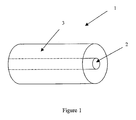
- the connecting element (1) illustrated on the figure 1 , consists of a cable (2) surrounded by a relatively flexible envelope (3). Said cable (2) consists, in turn, in a strand or elastic rod.
- strand is meant a strand consisting of either a single piece ("single strand”) or several son.
- said strand is coaxial with said envelope (3) so as to constitute the central core of said connecting element (1).
- said cable (2) will be called "central strand”, and will also be referenced under the number (2).
- Said envelope (3) consists of a flexible polymer, such as polyurethane or PEEK (polyetheretherketone).
- said sheath is a biocompatible fabric.
- said cable when it comprises only one strand, is advantageously made of titanium alloy, PEEK, or super-elastic alloy of the Nickel / Titanium alloy type, also known as Nitinol®.
- one or more layers of successive strands are arranged around said central strand (2).
- FIGS. 2 and 3 in particular illustrate a connecting element (1) comprising a layer (4) of six strands (40) distributed around said central strand (2).
- said strands (40) are arranged twisted around said central strand (2).
- said connecting element (1) is characterized in that it comprises a second layer of strands, advantageously consisting of twelve strands, and surrounding said first layer (4) of six strands (40).
- the choice of the shape and the constitution of the cable will be guided by the constraint of the diameter, the goal being to realize a connecting element of small diameter (Preferably less than or equal to 6 millimeters) so that said connecting element is the least invasive possible.
- the strands of each layer are made of elastic materials.
- the strands constituting said layers and the central strand (2) consist of titanium, stainless steel or PEEK.
- said central strand (2) may also have a shape or dimensions different from those of the strands constituting said layers.
- said central strand (2) consists of a tube.
- said central strand is preferably made of PEEK, the strands of said layers being made of titanium or stainless steel.
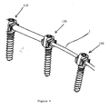
- the figure 4 illustrates a partial perspective view of a spinal fixation system (100).
- the fixation system includes a plurality of implantable connection assemblies. Only three of these implantable connection sets are represented on the figure 4 these three connection sets being respectively referenced 110, 120, 130.
- connection assembly (110) is connected to the connection assembly (120) by means of a spinal osteosynthesis connecting element, the connection assembly (120) being connected to the connection assembly (130) by means of a dynamic link element according to one of the embodiments illustrated on the Figures 1 to 3 .
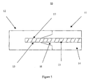
- FIG 5 illustrates a sectional view of a connecting element (10) according to a preferred embodiment of the invention.
- Said connecting element (10) is advantageous in that it constitutes a "semi-dynamic" connection.
- Said rod-shaped connecting element (10) consists of a flexible part (11) and a rigid part (12), said rigid part (12) being fixed in the extension of said flexible part (11). ).
- the "semi-dynamic" behavior of said connecting element (10) is conferred by each of the parts (11, 12), the flexible part (11) playing the role of dynamic link, and the rigid part (12) the connecting role. osteosynthesis.
- said flexible portion (11) consists of a cable (13) surrounded at least in part by a polymer envelope (14), said cable (13) consisting of at least one elastic strand coaxial with said envelope ( 14). Said cable (13) has at one of its ends a stripped zone (17) of said envelope (14).
- the rigid portion (12) has a blind cavity (15) in which is housed the bare area (17) of said cable (13).
- said cavity (15) is configured to allow close cooperation with said cable (13).
- said flexible portion (11), and therefore said cable are regularly subjected to oscillations.
- a movement generates a risk of shearing said cable (13).
- said cable (13) is flexed against the cutting edges formed by the side walls of said cavity (15) and the face constituting the end of the rigid portion (12).
- said cavity (15) has on the open end, a flared zone (16).
- Said blind cavity (15) is formed longitudinally in the rigid portion (12) by drilling.
- the cable (13) is then introduced into said cavity (15) until reaching the closed end of said cavity (15).
- the portion of the cable (13) inserted in the cavity (15) is fixed therein by gluing or crimping.
- the final step consists in forming the envelope (14) by injecting a polymer around the portion of the cable (13) not inserted into the cavity (15).
- said connecting element (10) is made such that said cable (13) is coaxial with the rigid portion (12).
- said cable (13) consists of either a single elastic strand or an elastic strand surrounded by one or more successive layers of strands, said strands of said layers being advantageously twisted.
- the semi-dynamic link element (10) is not limited to the configuration illustrated on the figure 5 . Indeed, it is of course obvious that the flexible portion may advantageously be extended on both sides by a rigid portion.
- the length of the flexible portion and the rigid portion or portions will depend on the type of desired links between each adjacent vertebra.
- the dynamic link element may advantageously be formed of a plurality of flexible portions separated from each other by a rigid portion.
Landscapes
- Health & Medical Sciences (AREA)
- Orthopedic Medicine & Surgery (AREA)
- Neurology (AREA)
- Life Sciences & Earth Sciences (AREA)
- Surgery (AREA)
- Biomedical Technology (AREA)
- Engineering & Computer Science (AREA)
- General Health & Medical Sciences (AREA)
- Heart & Thoracic Surgery (AREA)
- Animal Behavior & Ethology (AREA)
- Public Health (AREA)
- Veterinary Medicine (AREA)
- Medical Informatics (AREA)
- Molecular Biology (AREA)
- Nuclear Medicine, Radiotherapy & Molecular Imaging (AREA)
- Oral & Maxillofacial Surgery (AREA)
- Cardiology (AREA)
- Transplantation (AREA)
- Vascular Medicine (AREA)
- Prostheses (AREA)
- Surgical Instruments (AREA)
- Joining Of Building Structures In Genera (AREA)
- Coupling Device And Connection With Printed Circuit (AREA)
- Clamps And Clips (AREA)
- Information Retrieval, Db Structures And Fs Structures Therefor (AREA)
- Materials For Medical Uses (AREA)
Description
- La présente invention se rapporte au domaine des systèmes de fixation rachidiens pour la liaison de vertèbres entre elles, et plus particulièrement au domaine des éléments de liaison destinés à maintenir un espacement entre au moins deux éléments d'ancrage implantés respectivement dans une vertèbre.
- Il existe actuellement deux types de liaisons rachidiennes : d'une part les liaisons d'ostéosynthèse, et d'autre part les liaisons dynamiques.
- Les liaisons d'ostéosynthèse rachidiennes sont des liaisons bien connues. Elles sont en effet couramment utilisées pour consolider plusieurs vertèbres consécutives. Elles ont pour but de figer les vertèbres liées dans une configuration particulière et de stabiliser celles-ci pendant la fusion osseuse afin de permettre une stabilisation fixe dans la situation figée. De telles liaisons consistent en des tiges rigides.
- A contrario, les liaisons dynamiques sont utilisées pour réduire les contraintes sur les facettes articulaires et sur les disques intervertébraux en autorisant certains mouvements, tout en réalignant, si nécessaire, les vertèbres les unes par rapport aux autres.
- L'art antérieur connaît déjà de tels éléments de liaison.
- En particulier, il est proposé dans la demande de brevet
européen EP0669109 un dispositif de stabilisation de vertèbres dorsales avoisinantes. Ledit dispositif comporte un élément de liaison constitué d'une bande réalisée en matière synthétique élastique et présentant une section transversale ronde. Cette bande est destinée à être fixée entre au moins deux vis pédiculaires constituées respectivement d'une tête munie d'un perçage transversal. La fixation de ladite bande sur lesdites vis pédiculaires est réalisée en insérant à travers du perçage transversal ladite bande, laquelle est ensuite fixée sur chacune desdites vis pédiculaire au moyen d'une vis de serrage disposée selon l'axe de la vis correspondante, soit transversalement au perçage. Ledit dispositif comporte en outre un élément d'appui monté autour de ladite bande afin de former un corps résistant à la pression. - Un tel élément de liaison présente cependant l'inconvénient de n'effectuer aucun rappel en torsion afin de s'opposer à des mouvements de pivotement des vertèbres autour des disques.
- Un autre inconvénient important de cet élément de liaison est qu'il ne peut pas être cintré de façon à s'adapter à la lordose naturelle du rachis lombaire.
- En outre, un autre inconvénient est que l'élément de liaison occupe un volume important (de l'ordre de 12,5 millimètres). Dans certaines circonstances, il peut s'avérer difficile d'empêcher que l'élément de liaison en question ne rentre en contact avec des os, un tel contact provoquant de fortes douleurs.
- Par ailleurs, un tel dispositif présente un inconvénient particulièrement important lié au fait de la nécessité de choisir la longueur de l'élément d'appui avant la mise en place de ladite bande. Il peut arriver cependant que la distance effective entre les vis après mise en tension de la bande ne soit pas exactement celle souhaitée. Or, le dispositif tel que configuré ne permet aucune liberté de distraction et/ou de compression entre les vis après la mise en place de la bande et de l'élément d'appui. Le chirurgien n'a donc d'autre choix que de démonter l'ensemble élément d'appui et bande pour introduire un nouvel élément d'appui présentant une longueur différente.
- Il est également proposé, dans la demande de brevet internationale
WO02/07621 - Cette pièce de liaison présente cependant l'inconvénient de ne pouvoir fléchir que dans une direction bien déterminée, à savoir dans la perpendiculaire au plan moyen que forme les deux branches. Il s'ensuit un montage de l'ensemble du système de stabilisation comprenant de telles pièces de liaison nécessitant une certaine précision et donc pouvant s'avérer fastidieux.
- Un autre inconvénient d'une telle pièce de liaison s'avère être également son volume.
- La demande de brevet
US5704936 , étant l'état de la technique le plus proche de l'invention, décrit un élément de liaison pour un système de fixation rachidien, destiné à lier au moins deux ensembles de connexion implantables. L'élément de liaison est constitué par une tige comprenant une partie souple comportant un câble lequel est constitué d'au moins un brin élastique. - Un premier objet de l'invention est de remédier aux inconvénients des éléments de liaison dynamique décrits précédemment en proposant un élément de liaison présentant une amplitude de flexion équivalente au regard de ces éléments de liaison dynamiques, mais dont le maintien en rotation est assuré.
- Ledit élément de liaison objet de l'invention a également pour avantage de pouvoir être cintré de façon à s'adapter à la lordose naturelle du rachis lombaire.
- Ledit élément de liaison objet de l'invention présente également l'avantage d'être peu invasif, tout en assurant les fonctionnalités exigées pour un élément de liaison dynamique (flexibilité, résistance à l'usure, ...).
- Ledit élément de liaison présente encore l'avantage de permettre un montage rapide sur les éléments d'ancrage fixés sur les vertèbres.
- Ledit élément de liaison présente enfin l'avantage de pouvoir subir une distraction et/ou une compression après sa mise en place sur les éléments d'ancrage.
- Pour ce faire, la présente invention concerne un élément de liaison pour un système de fixation rachidien, destiné à lier au moins deux ensembles de connexion implantables, ledit élément de liaison étant remarquable en ce qu'il est constitué d'un câble et d'une enveloppe en polymère entourant ledit câble, ledit câble étant constitué d'au moins un brin élastique coaxial avec ladite enveloppe de sorte à former l'âme de l'élément de liaison.
- Afin d'alléger la suite de la description, ledit brin formant l'âme dudit élément de liaison est défini en tant que brin central.
- De préférence, ledit élément de liaison comporte au moins une couche de 6 brins au moins répartis autour dudit brin central.
- Selon une configuration avantageuse de l'invention, ledit élément de liaison comporte deux couches de brins successives disposées autour dudit brin central, la première couche de brins entourant ledit brin central étant constituée de 6 brins, la seconde couche de brins entourant ladite première couche étant constituée de 12 brins.
- Avantageusement, les brins constituant la (ou les) couche(s) consistent en des brins torsadés autour dudit brin central.
- Avantageusement, les brins de la (ou des) couche(s) sont constitués d'un matériau différent de celui dudit brin central.
- Avantageusement, le brin central présente un diamètre différent de celui des brins de la (ou desdites) couche(s). Selon le type de configuration souhaitée, il peut être inférieur ou supérieur à celui des brins desdites couches.
- Avantageusement, les brins constituant la (ou les) couche(s) sont constitués de titane ou d'inox.
- Avantageusement, le brin central est tubulaire.
- Avantageusement, le brin central est constitué d'un alliage de Nickel-Titane, de Titane, d'Inox ou de Polymère, comme par exemple de PEEK ou de Polyuréthane.
- Avantageusement, ladite enveloppe est en Polyuréthane, en PEEK, ou constituée d'un tissu biocompatible.
- Un second objet de l'invention est de proposer un élément de liaison combinant les fonctionnalités d'un élément de liaison dynamique à celles d'un élément de liaison d'ostéosynthèse. Plus particulièrement, ledit élément de liaison a pour objet de proposer, conjointement à une liaison dynamique de deux vertèbres au moins, la liaison rigide d'autres vertèbres.
- En effet, dans le cas de la mise en place d'un système de fixation et de stabilisation de vertèbres multi niveaux (instrumentation de plusieurs vertèbres), il peut s'avérer nécessaire de lier certaines vertèbres entre elles au moyen d'une liaison dynamique afin d'autoriser certains mouvements, et au contraire de lier les autres vertèbres de façon à ce qu'aucun mouvement ne soit autorisé durant la fusion osseuse (liaison d'ostéosynthèse). Dans les systèmes de fixation et de stabilisation actuels, les éléments de liaison dynamiques sont reliés aux éléments de liaison rigides au moyen d'éléments de fixation supplémentaires tels que des dominos. L'utilisation de pièces supplémentaires a pour inconvénient d'augmenter le temps de montage des éléments de liaison sur les éléments d'ancrage.
- La présente invention se rapporte donc également à un élément de liaison pour un système de fixation rachidien, destiné à lier au moins deux ensembles de connexion implantables, caractérisé en ce qu'il comprend une partie souple prolongée à l'une de ses extrémités au moins par une partie rigide, ladite partie souple comportant un câble entouré au moins en partie par une enveloppe en polymère, ledit câble étant constitué d'au moins un brin élastique coaxial avec ladite enveloppe.
- L'élément de liaison ainsi configuré permet d'offrir des « liaisons » dynamiques et rigides de vertèbres sans avoir recours à des éléments de fixation supplémentaires.
- Cet élément de liaison est défini dans la suite de la description comme étant un élément de liaison semi-dynamique.
- Par ailleurs, et de même que précédemment, afin d'alléger la suite de la description, ledit brin élastique est nommé en « brin central ».
- De préférence, ladite partie rigide présente une cavité destinée à recevoir au moins en partie ledit câble, ladite cavité étant borgne ou traversante.
- Avantageusement, ladite cavité est configurée pour coopérer étroitement avec ledit câble.
- Avantageusement, ladite cavité présente une zone évasée en direction de l'extrémité recevant ledit câble.
- Avantageusement, la partie souple est fixée sur ladite partie rigide par collage, sertissage ou soudure.
- De préférence, ledit câble comporte, de préférence, au moins une couche de 6 brins au moins, lesdits brins étant répartis autour dudit brin central. Selon une configuration avantageuse de l'invention, ledit câble comporte deux couches de brins successives disposées autour dudit brin central, la première couche de brins entourant ledit brin central étant constituée de 6 brins, la seconde couche de brins entourant ladite première couche étant constituée de 12 brins.
- Avantageusement, les brins constituant la (ou les) couche(s) consistent en des brins torsadés autour dudit brin central.
- Avantageusement, les brins de la (ou des) couche(s) sont constitués d'un matériau différent de celui dudit brin central.
- Avantageusement, le brin central est de diamètre différent de celui des brins de la (ou desdites) couche(s).
- Avantageusement, les brins constituant la (ou les) couche(s) sont constitués de titane ou d'inox.
- Avantageusement, le brin central est tubulaire.
- Avantageusement, le brin central est constitué d'un alliage de Nickel-Titane, de Titane, d'Inox ou de Polymère, comme par exemple du PEEK ou du Polyuréthane.
- Avantageusement, ladite enveloppe est en Polyuréthane, en PEEK, ou constituée d'un tissu biocompatible.
- La présente invention se rapporte également à un système de fixation rachidien comportant au moins deux ensembles de connexion implantables liés à l'aide au moins d'un ou des deux éléments de liaison précédemment décrits.
- On comprendra mieux l'invention à l'aide de la description, faite ci-après à titre purement explicatif, d'un mode de réalisation de l'invention, en référence aux figures annexée :
- la
figure 1 illustre une vue latérale en perspective d'un élément de liaison dynamique selon l'invention ; - la
figure 2 illustre une variante de réalisation de l'élément de liaison de lafigure 1 ; - la
figure 3 illustre une vue en coupe de l'élément de liaison de lafigure 2 ; - la
figure 4 illustre une vue partielle en perspective d'un système de fixation rachidien comprenant des éléments de liaison rigide et des éléments de liaison dynamiques selon l'invention ; et - la
figure 5 illustre une vue en coupe d'un élément de liaison semi-dynamique selon un mode de réalisation préféré de l'invention. - Les éléments de liaison (1), représentés sur les
figures 1 à 4 , constituent des liaisons dynamiques telles que définies précédemment. Ces éléments de liaison sont destinés à lier au moins deux ensembles de connexion implantables. - L'élément de liaison (1), illustré sur la
figure 1 , est constitué d'un câble (2) entouré d'une enveloppe (3) relativement souple. Ledit câble (2) consiste, quant à lui, en un brin ou tige élastique. - Par brin, on entend un brin constitué soit d'un seul tenant (« monobrin »), soit de plusieurs fils.
- Avantageusement, ledit brin est coaxial avec ladite enveloppe (3) de sorte à constituer l'âme centrale dudit élément de liaison (1).
- Dans ce qui suit, ledit câble (2) sera nommé « brin central », et sera référencé également sous le chiffre (2).
- Ladite enveloppe (3) est constituée d'un polymère souple, tel que le Polyuréthane ou le PEEK (polyétheréthercétone). Dans une configuration particulière de l'invention, ladite gaine est un tissu biocompatible.
- Parallèlement, afin d'offrir le rappel nécessaire pour s'opposer aux mouvements de pivotement des vertèbres autour des disques, ledit câble, lorsqu'il ne comprend qu'un seul brin, est avantageusement constitué en alliage de Titane, en PEEK, ou en alliage super élastique du type alliage Nickel / Titane, également connu sous le nom de Nitinol®.
- Afin d'améliorer la caractéristique relative à l'élasticité de l'élément de liaison, une ou plusieurs couches de brins successives sont disposées autour dudit brin central (2).
- Les
figures 2 et 3 illustrent en particulier un élément de liaison (1) comportant une couche (4) de six brins (40) répartis autour dudit brin central (2). - Avantageusement, lesdits brins (40) sont disposés torsadés autour dudit brin central (2).
- Selon un autre mode de réalisation préférentiel de l'invention, ledit élément de liaison (1) est caractérisé, en ce qu'il comporte une seconde couche de brins, constituée avantageusement de douze brins, et entourant ladite première couche (4) de six brins (40).
- Ces deux configurations de couches sont ici données à titre d'exemple. Il est bien entendu évident pour l'homme du métier que l'organisation et le nombre de couches de brins, ainsi que le nombre de brins par couche et leur configuration, seront fonction de la rigidité (ou élasticité) souhaitée pour ledit élément de liaison (1).
- Cependant, le choix de la forme et de la constitution du câble sera guidé par la contrainte du diamètre, le but étant de réaliser un élément de liaison de faible diamètre (de préférence inférieur ou égal à 6 millimètres) de sorte que ledit élément de liaison soit le moins invasif possible.
- De même que le brin central (2), les brins de chacune des couches sont en matériaux élastiques. Avantageusement, les brins constituant lesdites couches ainsi que le brin central (2) sont constitués de Titane, d'Inox ou PEEK.
- Il est à noter cependant qu'il n'est cependant pas nécessaire que les brins constituant lesdites couches soient réalisées dans le même matériau que celui dans lequel est réalisé ledit brin central (2).
- De même, ledit brin central (2) peut présenter également une forme ou des dimensions différentes de celles des brins constituant lesdites couches. Notamment, selon une configuration particulière de l'invention, ledit brin central (2) est constitué d'un tube. Dans ce cas, ledit brin central est de préférence en PEEK, les brins desdites couches étant en Titane ou Inox.
- La
figure 4 illustre une vue partielle en perspective d'un système de fixation rachidien (100). - Ledit système de fixation comprend une pluralité d'ensembles de connexion implantables. Seulement trois de ces ensembles de connexion implantables sont représentés sur la
figure 4 , ces trois ensembles de connexion étant respectivement référencés 110, 120, 130. - Chaque ensemble de connexion est respectivement relié à un ensemble de connexion voisin par un élément de liaison. En particulier, dans cet exemple de réalisation, l'ensemble de connexion (110) est relié à l'ensemble de connexion (120) au moyen d'un élément de liaison d'ostéosynthèse rachidienne, l'ensemble de connexion (120) étant relié à l'ensemble de connexion (130) au moyen d'un élément de liaison dynamique selon l'un des modes de réalisation illustrés sur les
figures 1 à 3 . - La combinaison d'éléments de liaison dynamique et d'éléments de liaison d'ostéosynthèse rachidienne permet ainsi de proposer un système de fixation modulable comprenant des éléments de liaison classique du type liaisons d'ostéosynthèse et des éléments de liaison dynamiques.
- La
figure 5 illustre une vue en coupe d'un élément de liaison (10) selon un mode de réalisation préféré de l'invention. Ledit élément de liaison (10) est avantageux en qu'il constitue une liaison « semi-dynamique ». - Ledit élément de liaison (10), en forme de tige, est constitué d'une partie souple (11) et d'une partie rigide (12), ladite partie rigide (12) étant fixée dans le prolongement de ladite partie souple (11). Le comportement « semi-dynamique » dudit élément de liaison (10) est conféré par chacune des parties (11, 12), la partie souple (11) jouant le rôle de liaison dynamique, et la partie rigide (12) le rôle de liaison d'ostéosynthèse.
- Avantageusement, ladite partie souple (11) est constituée d'un câble (13) entouré au moins en partie par une enveloppe en polymère (14), ledit câble (13) étant constitué d'au moins un brin élastique coaxial avec ladite enveloppe (14). Ledit câble (13) présente au niveau d'une de ses extrémités une zone dénudée (17) de ladite enveloppe (14).
- La partie rigide (12) présente une cavité (15) borgne dans laquelle vient se loger la zone dénudée (17) dudit câble (13). Avantageusement, ladite cavité (15) est configurée pour permettre une coopération étroite avec ledit câble (13).
- De par sa constitution et sa fonction, ladite partie souple (11), et donc ledit câble, sont régulièrement soumis à des oscillations. Or, un tel mouvement génère un risque de cisaillement dudit câble (13). En effet, ledit câble (13) est fléchi contre les arêtes coupantes formées par les parois latérales de ladite cavité (15) et la face constituant l'extrémité de la partie rigide (12). Aussi, et afin de limiter ce risque de cisaillement, ladite cavité (15) présente sur l'extrémité débouchante, une zone évasée (16).
- Le principe pour réaliser ledit élément de liaison (10) est comme suit.
- Ladite cavité (15) borgne est formée longitudinalement dans la partie rigide (12) par perçage. Le câble (13) est alors introduit dans ladite cavité (15) jusqu'à atteindre l'extrémité fermée de ladite cavité (15). La partie du câble (13) insérée dans la cavité (15) est fixée dans celle-ci par collage ou sertissage. Une fois le câble (13) disposé et fixé dans la cavité (15) de la partie rigide (12), l'étape finale consiste à former l'enveloppe (14) en injectant un polymère autour de la partie du câble (13) non insérée dans la cavité (15).
- Avantageusement, ledit élément de liaison (10) est réalisé de sorte que ledit câble (13) soit coaxial avec la partie rigide (12).
- De même que dans les exemples précédemment décrits, ledit câble (13) est constitué soit d'un seul brin élastique, soit d'un brin élastique entouré d'une ou plusieurs couches successives de brins, lesdits brins desdites couches étant avantageusement torsadés.
- Par ailleurs, la description faite précédemment relative à la constitution et la configuration du brin central et des brins des couches s'applique également dans le cadre de cette configuration.
- D'autre part, il est bien entendu évident que l'élément de liaison (10) semi-dynamique ne se limite pas à la configuration illustrée sur la
figure 5 . En effet, il est bien entendu évident que la partie souple pourra avantageusement être prolongée de part et d'autre par une partie rigide. - De même, dans le cas d'un système de stabilisation et de fixation de vertèbres multi niveaux, la longueur de la partie souple et de la ou des parties rigides sera fonction du type de liaisons souhaitées entre chaque vertèbre adjacente.
- Enfin, l'élément de liaison dynamique pourra avantageusement être formé d'une pluralité de parties souples séparées les unes des autres par une partie rigide.
- L'invention est décrite dans ce qui précède à titre d'exemple. Il est entendu que l'homme du métier est à même de réaliser différentes variantes de l'invention sans pour autant sortir du cadre du brevet.
Claims (19)
- Elément de liaison (10) pour un système de fixation rachidien, destiné à lier au moins deux ensembles de connexion implantables, l'élément de liaison étant constitué par une tige comprenant une partie souple (11) prolongée à l'une de ses extrémités au moins par une partie rigide (12), ladite partie souple (11) comportant un câble (13) entouré au moins en partie par une enveloppe (14) en polymère, ledit câble étant constitué d'au moins un brin élastique coaxial avec ladite enveloppe (14).
- Elément de liaison (10) selon la revendication 1, caractérisé en ce que ladite partie rigide présente une cavité (15) borgne destinée à recevoir au moins en partie ledit câble (13).
- Elément de liaison (10) selon la revendication 1, caractérisé en ce que ladite partie rigide présente une cavité (15) traversante destinée à recevoir au moins en partie ledit câble (13).
- Elément de liaison (10) selon la revendication 2 ou la revendication 3, caractérisé en ce que ladite cavité (15) est configurée pour coopérer avec ledit câble (13).
- Elément de liaison (10) selon l'une quelconque des revendications 2 à 4, caractérisé en ce que ladite cavité (15) présente une zone évasée (16) en direction de l'extrémité recevant ledit câble (13).
- Elément de liaison (10) selon l'une quelconque des revendications 1 à 5, caractérisé en ce que la partie souple (11) est fixée sur la partie rigide (12) par collage, sertissage ou soudure.
- Elément de liaison ( 10) selon l'une quelconque des revendications précédentes, caractérisé en ce que le câble (13) comporte au moins une couche (4) de 6 brins (40) au moins, lesdits brins étant répartis autour dudit brin central.
- Elément de liaison (10) selon l'une quelconque des revendications précédentes, caractérisé en ce que ledit câble comporte deux couches de brins successives disposées autour dudit brin central, la première couche de brins entourant ledit brin central étant constituée de 6 brins, la seconde couche de brins entourant ladite première couche étant constituée de 12 brins.
- Elément de liaison (10) selon la revendication 7 ou la revendication 8, caractérisé en ce que les brins constituant la (ou les) couche(s) consistent en des brins torsadés autour dudit brin central.
- Elément de liaison (10) selon l'une quelconque des revendications 7 à 9, caractérisé en ce que les brins de la (ou des) couche(s) sont constitués d'un matériau différent de celui dudit brin central.
- Elément de liaison (10) selon l'une quelconque des revendications 7 à 10, caractérisé en ce que le brin central est de diamètre différent de celui des brins de la (ou desdites) couche(s).
- Elément de liaison (10) selon l'une quelconque des revendications 7 à 11, caractérisé en ce que les brins constituant la (ou les) couche(s) sont constitués de Titane ou d'Inox, d'alliage Titane-Nickel.
- Elément de liaison (10) selon l'une quelconque des revendications 1 à 12, caractérisé en ce que le brin central est tubulaire.
- Elément de liaison (10) selon l'une quelconque des revendications 1 à 13, caractérisé en ce que le brin central est constitué d'un alliage de Nickel-Titane, de Titane, d'Inox ou de Polymère.
- Elément de liaison (10) selon la revendication précédente, caractérisé en ce que le brin central est en PEEK ou en Polyuréthane.
- Elément de liaison (10) selon l'une quelconque des revendications 1 à 15, caractérisé en ce que ladite enveloppe (14) est en Polyuréthane.
- Elément de liaison (10) selon l'une quelconque des revendications 1 à 15, caractérisé en ce que ladite enveloppe (14) est en PEEK.
- Elément de liaison (110) selon l'une quelconque des revendications 1 à 15, caractérisé en ce que ladite enveloppe (14) est constituée d'un tissu biocompatible.
- Système de fixation rachidien comportant au moins deux ensembles de connexion implantables liés au moyen au moins d'un élément de liaison (10) selon l'une quelconque des revendications 1 à 18.
Applications Claiming Priority (2)
| Application Number | Priority Date | Filing Date | Title |
|---|---|---|---|
| FR0402150A FR2867057B1 (fr) | 2004-03-02 | 2004-03-02 | Element de liaison dynamique pour un systeme de fixation rachidien et systeme de fixation comprenant un tel element de liaison |
| PCT/FR2005/000496 WO2005087121A1 (fr) | 2004-03-02 | 2005-03-02 | Element de liaison dynamique pour un systeme de fixation rachidien et systeme de fixation comprenant un tel element de liaison |
Publications (2)
| Publication Number | Publication Date |
|---|---|
| EP1720472A1 EP1720472A1 (fr) | 2006-11-15 |
| EP1720472B1 true EP1720472B1 (fr) | 2008-05-14 |
Family
ID=34854984
Family Applications (1)
| Application Number | Title | Priority Date | Filing Date |
|---|---|---|---|
| EP05732859A Expired - Lifetime EP1720472B1 (fr) | 2004-03-02 | 2005-03-02 | Element de liaison dynamique pour un systeme de fixation rachidien et systeme de fixation comprenant un tel element de liaison |
Country Status (15)
| Country | Link |
|---|---|
| US (1) | US8500780B2 (fr) |
| EP (1) | EP1720472B1 (fr) |
| JP (1) | JP4850823B2 (fr) |
| KR (1) | KR101151497B1 (fr) |
| CN (1) | CN100594006C (fr) |
| AT (1) | ATE394999T1 (fr) |
| AU (1) | AU2005221356B2 (fr) |
| DE (1) | DE602005006753D1 (fr) |
| DK (1) | DK1720472T3 (fr) |
| ES (1) | ES2307171T3 (fr) |
| FR (1) | FR2867057B1 (fr) |
| PT (1) | PT1720472E (fr) |
| RU (1) | RU2370234C2 (fr) |
| WO (1) | WO2005087121A1 (fr) |
| ZA (1) | ZA200607383B (fr) |
Families Citing this family (155)
| Publication number | Priority date | Publication date | Assignee | Title |
|---|---|---|---|---|
| FR2812186B1 (fr) | 2000-07-25 | 2003-02-28 | Spine Next Sa | Piece de liaison souple pour la stabilisation du rachis |
| FR2812185B1 (fr) | 2000-07-25 | 2003-02-28 | Spine Next Sa | Piece de liaison semi-rigide pour la stabilisation du rachis |
| US7833250B2 (en) | 2004-11-10 | 2010-11-16 | Jackson Roger P | Polyaxial bone screw with helically wound capture connection |
| ATE296580T1 (de) | 2000-09-18 | 2005-06-15 | Zimmer Gmbh | Pedikelschraube für intervertebrale stützelemente |
| US7862587B2 (en) | 2004-02-27 | 2011-01-04 | Jackson Roger P | Dynamic stabilization assemblies, tool set and method |
| US8292926B2 (en) | 2005-09-30 | 2012-10-23 | Jackson Roger P | Dynamic stabilization connecting member with elastic core and outer sleeve |
| US20160242816A9 (en) | 2001-05-09 | 2016-08-25 | Roger P. Jackson | Dynamic spinal stabilization assembly with elastic bumpers and locking limited travel closure mechanisms |
| US10729469B2 (en) | 2006-01-09 | 2020-08-04 | Roger P. Jackson | Flexible spinal stabilization assembly with spacer having off-axis core member |
| US10258382B2 (en) * | 2007-01-18 | 2019-04-16 | Roger P. Jackson | Rod-cord dynamic connection assemblies with slidable bone anchor attachment members along the cord |
| US8353932B2 (en) | 2005-09-30 | 2013-01-15 | Jackson Roger P | Polyaxial bone anchor assembly with one-piece closure, pressure insert and plastic elongate member |
| BR0117188A (pt) * | 2001-12-07 | 2004-11-09 | Mathys Medizinaltechnik Ag | Elemento de amortecimento |
| FR2842724B1 (fr) | 2002-07-23 | 2005-05-27 | Spine Next Sa | Systeme de fixation vertebrale |
| US8876868B2 (en) | 2002-09-06 | 2014-11-04 | Roger P. Jackson | Helical guide and advancement flange with radially loaded lip |
| US7621918B2 (en) | 2004-11-23 | 2009-11-24 | Jackson Roger P | Spinal fixation tool set and method |
| US7377923B2 (en) | 2003-05-22 | 2008-05-27 | Alphatec Spine, Inc. | Variable angle spinal screw assembly |
| US7967850B2 (en) | 2003-06-18 | 2011-06-28 | Jackson Roger P | Polyaxial bone anchor with helical capture connection, insert and dual locking assembly |
| US7776067B2 (en) | 2005-05-27 | 2010-08-17 | Jackson Roger P | Polyaxial bone screw with shank articulation pressure insert and method |
| US8092500B2 (en) | 2007-05-01 | 2012-01-10 | Jackson Roger P | Dynamic stabilization connecting member with floating core, compression spacer and over-mold |
| US7766915B2 (en) | 2004-02-27 | 2010-08-03 | Jackson Roger P | Dynamic fixation assemblies with inner core and outer coil-like member |
| US8936623B2 (en) | 2003-06-18 | 2015-01-20 | Roger P. Jackson | Polyaxial bone screw assembly |
| US8366753B2 (en) | 2003-06-18 | 2013-02-05 | Jackson Roger P | Polyaxial bone screw assembly with fixed retaining structure |
| US20050065516A1 (en) * | 2003-09-24 | 2005-03-24 | Tae-Ahn Jahng | Method and apparatus for flexible fixation of a spine |
| US7763052B2 (en) * | 2003-12-05 | 2010-07-27 | N Spine, Inc. | Method and apparatus for flexible fixation of a spine |
| US20050203513A1 (en) * | 2003-09-24 | 2005-09-15 | Tae-Ahn Jahng | Spinal stabilization device |
| US8979900B2 (en) | 2003-09-24 | 2015-03-17 | DePuy Synthes Products, LLC | Spinal stabilization device |
| US7815665B2 (en) * | 2003-09-24 | 2010-10-19 | N Spine, Inc. | Adjustable spinal stabilization system |
| US7179261B2 (en) | 2003-12-16 | 2007-02-20 | Depuy Spine, Inc. | Percutaneous access devices and bone anchor assemblies |
| US11419642B2 (en) | 2003-12-16 | 2022-08-23 | Medos International Sarl | Percutaneous access devices and bone anchor assemblies |
| US7527638B2 (en) | 2003-12-16 | 2009-05-05 | Depuy Spine, Inc. | Methods and devices for minimally invasive spinal fixation element placement |
| US8029548B2 (en) | 2008-05-05 | 2011-10-04 | Warsaw Orthopedic, Inc. | Flexible spinal stabilization element and system |
| US8562649B2 (en) * | 2004-02-17 | 2013-10-22 | Gmedelaware 2 Llc | System and method for multiple level facet joint arthroplasty and fusion |
| US8152810B2 (en) | 2004-11-23 | 2012-04-10 | Jackson Roger P | Spinal fixation tool set and method |
| US7160300B2 (en) | 2004-02-27 | 2007-01-09 | Jackson Roger P | Orthopedic implant rod reduction tool set and method |
| US11241261B2 (en) | 2005-09-30 | 2022-02-08 | Roger P Jackson | Apparatus and method for soft spinal stabilization using a tensionable cord and releasable end structure |
| WO2005092218A1 (fr) | 2004-02-27 | 2005-10-06 | Jackson Roger P | Ensemble d'instruments de reduction de tige d'implant orthopedique et methode associee |
| US7901435B2 (en) | 2004-05-28 | 2011-03-08 | Depuy Spine, Inc. | Anchoring systems and methods for correcting spinal deformities |
| CA2576636A1 (fr) * | 2004-08-18 | 2006-03-02 | Archus Orthopedics, Inc. | Dispositifs d'arthroplastie a facette pour le traitement de la degenerescence de segment adjacent, systemes de stabilisation de colonne vertebrale et methodes |
| US7651502B2 (en) | 2004-09-24 | 2010-01-26 | Jackson Roger P | Spinal fixation tool set and method for rod reduction and fastener insertion |
| DE102004048938B4 (de) * | 2004-10-07 | 2015-04-02 | Synthes Gmbh | Vorrichtung zur dynamischen Stabilisierung von Rückenwirbelkörpern |
| US8162985B2 (en) | 2004-10-20 | 2012-04-24 | The Board Of Trustees Of The Leland Stanford Junior University | Systems and methods for posterior dynamic stabilization of the spine |
| US8226690B2 (en) | 2005-07-22 | 2012-07-24 | The Board Of Trustees Of The Leland Stanford Junior University | Systems and methods for stabilization of bone structures |
| US8267969B2 (en) | 2004-10-20 | 2012-09-18 | Exactech, Inc. | Screw systems and methods for use in stabilization of bone structures |
| US8025680B2 (en) | 2004-10-20 | 2011-09-27 | Exactech, Inc. | Systems and methods for posterior dynamic stabilization of the spine |
| US7935134B2 (en) | 2004-10-20 | 2011-05-03 | Exactech, Inc. | Systems and methods for stabilization of bone structures |
| JP2008519656A (ja) | 2004-11-10 | 2008-06-12 | ロジャー・ピー・ジャクソン | 破断伸張部付の螺旋状案内及び前進フランジ |
| US8926672B2 (en) | 2004-11-10 | 2015-01-06 | Roger P. Jackson | Splay control closure for open bone anchor |
| US9216041B2 (en) | 2009-06-15 | 2015-12-22 | Roger P. Jackson | Spinal connecting members with tensioned cords and rigid sleeves for engaging compression inserts |
| US9168069B2 (en) | 2009-06-15 | 2015-10-27 | Roger P. Jackson | Polyaxial bone anchor with pop-on shank and winged insert with lower skirt for engaging a friction fit retainer |
| WO2006057837A1 (fr) | 2004-11-23 | 2006-06-01 | Jackson Roger P | Structure d'accrochage pour outil de fixation spinale |
| US9980753B2 (en) | 2009-06-15 | 2018-05-29 | Roger P Jackson | pivotal anchor with snap-in-place insert having rotation blocking extensions |
| US8444681B2 (en) | 2009-06-15 | 2013-05-21 | Roger P. Jackson | Polyaxial bone anchor with pop-on shank, friction fit retainer and winged insert |
| EP1719468A1 (fr) | 2004-12-17 | 2006-11-08 | Zimmer GmbH | Système de stabilisation intervertébrale du rachis |
| EP1841375A1 (fr) * | 2005-01-26 | 2007-10-10 | AESCULAP AG & Co. KG | Tige rachidienne à automodelage |
| US10076361B2 (en) | 2005-02-22 | 2018-09-18 | Roger P. Jackson | Polyaxial bone screw with spherical capture, compression and alignment and retention structures |
| US7901437B2 (en) * | 2007-01-26 | 2011-03-08 | Jackson Roger P | Dynamic stabilization member with molded connection |
| US20060212033A1 (en) * | 2005-03-03 | 2006-09-21 | Accin Corporation | Vertebral stabilization using flexible rods |
| US8523865B2 (en) | 2005-07-22 | 2013-09-03 | Exactech, Inc. | Tissue splitter |
| FR2890850B1 (fr) | 2005-09-20 | 2009-04-17 | Abbott Spine Sa | Systeme de fixation vertebrale |
| FR2890851B1 (fr) | 2005-09-21 | 2008-06-20 | Abbott Spine Sa | Ancillaire de mise en tension d'un lien souple. |
| WO2007038429A1 (fr) | 2005-09-27 | 2007-04-05 | Endius, Inc. | Procédés et appareils de stabilisation de la colonne vertébrale par le biais d’un dispositif d’accès |
| US8105368B2 (en) | 2005-09-30 | 2012-01-31 | Jackson Roger P | Dynamic stabilization connecting member with slitted core and outer sleeve |
| US8357181B2 (en) | 2005-10-27 | 2013-01-22 | Warsaw Orthopedic, Inc. | Intervertebral prosthetic device for spinal stabilization and method of implanting same |
| US20070118119A1 (en) * | 2005-11-18 | 2007-05-24 | Zimmer Spine, Inc. | Methods and device for dynamic stabilization |
| US20070173822A1 (en) * | 2006-01-13 | 2007-07-26 | Sdgi Holdings, Inc. | Use of a posterior dynamic stabilization system with an intradiscal device |
| US7578849B2 (en) * | 2006-01-27 | 2009-08-25 | Warsaw Orthopedic, Inc. | Intervertebral implants and methods of use |
| US7815663B2 (en) | 2006-01-27 | 2010-10-19 | Warsaw Orthopedic, Inc. | Vertebral rods and methods of use |
| US7682376B2 (en) | 2006-01-27 | 2010-03-23 | Warsaw Orthopedic, Inc. | Interspinous devices and methods of use |
| US20070191842A1 (en) * | 2006-01-30 | 2007-08-16 | Sdgi Holdings, Inc. | Spinal fixation devices and methods of use |
| EP2032055A2 (fr) * | 2006-06-28 | 2009-03-11 | Synthes GmbH | Système de fixation dynamique |
| EP2049030A4 (fr) * | 2006-07-24 | 2012-07-18 | Nuvasive Inc | Systèmes et procédés pour une stabilisation vertébrale dynamique |
| US7806913B2 (en) * | 2006-08-16 | 2010-10-05 | Depuy Spine, Inc. | Modular multi-level spine stabilization system and method |
| EP2047813A1 (fr) | 2007-10-11 | 2009-04-15 | Abbott Spine | Système de fixation d'os et procédé d'utilisation |
| US7947045B2 (en) | 2006-10-06 | 2011-05-24 | Zimmer Spine, Inc. | Spinal stabilization system with flexible guides |
| US8096996B2 (en) | 2007-03-20 | 2012-01-17 | Exactech, Inc. | Rod reducer |
| US7824430B2 (en) * | 2006-12-08 | 2010-11-02 | Warsaw Orthopedic, Inc. | Methods and devices for treating a multi-level spinal deformity |
| EP2088945A4 (fr) | 2006-12-08 | 2010-02-17 | Roger P Jackson | Systeme d'instruments pour implants rachidiens dynamiques |
| CN101199432B (zh) * | 2006-12-14 | 2010-09-22 | 叶安时 | 一种挠性缆脊椎固定装置 |
| US8029544B2 (en) | 2007-01-02 | 2011-10-04 | Zimmer Spine, Inc. | Spine stiffening device |
| US11224463B2 (en) | 2007-01-18 | 2022-01-18 | Roger P. Jackson | Dynamic stabilization connecting member with pre-tensioned flexible core member |
| US8366745B2 (en) * | 2007-05-01 | 2013-02-05 | Jackson Roger P | Dynamic stabilization assembly having pre-compressed spacers with differential displacements |
| US8475498B2 (en) * | 2007-01-18 | 2013-07-02 | Roger P. Jackson | Dynamic stabilization connecting member with cord connection |
| US8109975B2 (en) | 2007-01-30 | 2012-02-07 | Warsaw Orthopedic, Inc. | Collar bore configuration for dynamic spinal stabilization assembly |
| US8029547B2 (en) | 2007-01-30 | 2011-10-04 | Warsaw Orthopedic, Inc. | Dynamic spinal stabilization assembly with sliding collars |
| US8012177B2 (en) | 2007-02-12 | 2011-09-06 | Jackson Roger P | Dynamic stabilization assembly with frusto-conical connection |
| US8292929B2 (en) | 2007-03-16 | 2012-10-23 | Zimmer Spine, Inc. | Dynamic spinal stabilization system and method of using the same |
| US8057516B2 (en) | 2007-03-21 | 2011-11-15 | Zimmer Spine, Inc. | Spinal stabilization system with rigid and flexible elements |
| US8052727B2 (en) | 2007-03-23 | 2011-11-08 | Zimmer Gmbh | System and method for insertion of flexible spinal stabilization element |
| US7922725B2 (en) | 2007-04-19 | 2011-04-12 | Zimmer Spine, Inc. | Method and associated instrumentation for installation of spinal dynamic stabilization system |
| US8979904B2 (en) | 2007-05-01 | 2015-03-17 | Roger P Jackson | Connecting member with tensioned cord, low profile rigid sleeve and spacer with torsion control |
| US10383660B2 (en) | 2007-05-01 | 2019-08-20 | Roger P. Jackson | Soft stabilization assemblies with pretensioned cords |
| US8016832B2 (en) | 2007-05-02 | 2011-09-13 | Zimmer Spine, Inc. | Installation systems for spinal stabilization system and related methods |
| WO2008153827A1 (fr) | 2007-05-31 | 2008-12-18 | Jackson Roger P | Élément de raccord à stabilisation dynamique avec noyau solide précontraint |
| US20080312704A1 (en) * | 2007-06-12 | 2008-12-18 | Zimmer Spine, Inc. | Instrumentation and associated techniques for minimally invasive spinal construct installation |
| US8292925B2 (en) | 2007-06-19 | 2012-10-23 | Zimmer Spine, Inc. | Flexible member with variable flexibility for providing dynamic stability to a spine |
| JP2010535593A (ja) * | 2007-08-07 | 2010-11-25 | ジンテス ゲゼルシャフト ミット ベシュレンクテル ハフツング | ダイナミックケーブルシステム |
| US20090082815A1 (en) * | 2007-09-20 | 2009-03-26 | Zimmer Gmbh | Spinal stabilization system with transition member |
| EP2047811B1 (fr) * | 2007-10-11 | 2011-03-30 | BIEDERMANN MOTECH GmbH | Fixation forcée pour fixer une barre dans un dispositif chirurgical, par exemple dans un dispositif de stabilisation de la colonne vertébrale |
| ES2374577T3 (es) * | 2007-10-11 | 2012-02-20 | Biedermann Motech Gmbh | Sistema de varilla modular para la estabilización de la columna vertebral. |
| US20090099606A1 (en) * | 2007-10-16 | 2009-04-16 | Zimmer Spine Inc. | Flexible member with variable flexibility for providing dynamic stability to a spine |
| US8128635B2 (en) | 2007-10-23 | 2012-03-06 | Zimmer Spine S.A.S. | Bone fixation tensioning tool and method |
| US8911477B2 (en) | 2007-10-23 | 2014-12-16 | Roger P. Jackson | Dynamic stabilization member with end plate support and cable core extension |
| ATE536824T1 (de) | 2007-10-23 | 2011-12-15 | Zimmer Spine | Befestigungsvorrichtungen und stabilisierungssysteme mit diesen befestigungsvorrichtungen |
| US8043339B2 (en) * | 2007-10-24 | 2011-10-25 | Zimmer Spine, Inc. | Flexible member for use in a spinal column and method for making |
| FR2926976B1 (fr) * | 2008-02-04 | 2011-01-14 | Spinevision | Element de stabilisation dynamique pour vertebres. |
| USD620109S1 (en) | 2008-02-05 | 2010-07-20 | Zimmer Spine, Inc. | Surgical installation tool |
| US9277940B2 (en) | 2008-02-05 | 2016-03-08 | Zimmer Spine, Inc. | System and method for insertion of flexible spinal stabilization element |
| US20090248077A1 (en) * | 2008-03-31 | 2009-10-01 | Derrick William Johns | Hybrid dynamic stabilization |
| ATE515239T1 (de) | 2008-04-24 | 2011-07-15 | Zimmer Spine | System zur stabilisierung von mindestens einem abschnitt der wirbelsäule |
| EP2113216B1 (fr) * | 2008-04-28 | 2012-05-30 | Biedermann Technologies GmbH & Co. KG | Élément en forme de tige pour la stabilisation de la colonne vertébrale et procédé de production de celui-ci |
| EP2298199B1 (fr) * | 2008-05-06 | 2012-05-23 | Biedermann Technologies GmbH & Co. KG | Implant en forme de tige, en particulier pour la stabilisation dynamique de la colonne vertébrale |
| AU2009248781A1 (en) | 2008-05-20 | 2009-11-26 | Zimmer Spine | System for stabilizing at least three vertebrae |
| CA2739997C (fr) | 2008-08-01 | 2013-08-13 | Roger P. Jackson | Element longitudinal de liaison avec cordons tendus gaines |
| US20100049252A1 (en) * | 2008-08-21 | 2010-02-25 | Southern Spine, Llc | Transverse Connector Device for Extending an Existing Spinal Fixation System |
| EP2160988B1 (fr) * | 2008-09-04 | 2012-12-26 | Biedermann Technologies GmbH & Co. KG | Implant en forme de tige, en particulier pour stabiliser la colonne vertébrale et dispositif de stabilisation incluant un tel implant en forme de tige |
| US20100137908A1 (en) * | 2008-12-01 | 2010-06-03 | Zimmer Spine, Inc. | Dynamic Stabilization System Components Including Readily Visualized Polymeric Compositions |
| US9055979B2 (en) | 2008-12-03 | 2015-06-16 | Zimmer Gmbh | Cord for vertebral fixation having multiple stiffness phases |
| US8137355B2 (en) | 2008-12-12 | 2012-03-20 | Zimmer Spine, Inc. | Spinal stabilization installation instrumentation and methods |
| WO2010078029A1 (fr) | 2008-12-17 | 2010-07-08 | Synthes Usa, Llc | Stabilisateur dynamique vertébral postérieur |
| US8137356B2 (en) | 2008-12-29 | 2012-03-20 | Zimmer Spine, Inc. | Flexible guide for insertion of a vertebral stabilization system |
| US20100217319A1 (en) * | 2009-02-24 | 2010-08-26 | Abbott Spine Inc. | System and method for spinal stabilization |
| US8118840B2 (en) | 2009-02-27 | 2012-02-21 | Warsaw Orthopedic, Inc. | Vertebral rod and related method of manufacture |
| US11229457B2 (en) | 2009-06-15 | 2022-01-25 | Roger P. Jackson | Pivotal bone anchor assembly with insert tool deployment |
| US9668771B2 (en) | 2009-06-15 | 2017-06-06 | Roger P Jackson | Soft stabilization assemblies with off-set connector |
| US8998959B2 (en) | 2009-06-15 | 2015-04-07 | Roger P Jackson | Polyaxial bone anchors with pop-on shank, fully constrained friction fit retainer and lock and release insert |
| CN103826560A (zh) | 2009-06-15 | 2014-05-28 | 罗杰.P.杰克逊 | 具有套接杆和带摩擦配合压缩套爪的带翼插件的多轴骨锚 |
| US8876867B2 (en) | 2009-06-24 | 2014-11-04 | Zimmer Spine, Inc. | Spinal correction tensioning system |
| US20110009906A1 (en) * | 2009-07-13 | 2011-01-13 | Zimmer Spine, Inc. | Vertebral stabilization transition connector |
| US8657856B2 (en) | 2009-08-28 | 2014-02-25 | Pioneer Surgical Technology, Inc. | Size transition spinal rod |
| US9011494B2 (en) | 2009-09-24 | 2015-04-21 | Warsaw Orthopedic, Inc. | Composite vertebral rod system and methods of use |
| AU2010303934B2 (en) | 2009-10-05 | 2014-03-27 | Roger P. Jackson | Polyaxial bone anchor with non-pivotable retainer and pop-on shank, some with friction fit |
| US8328849B2 (en) | 2009-12-01 | 2012-12-11 | Zimmer Gmbh | Cord for vertebral stabilization system |
| US8740945B2 (en) | 2010-04-07 | 2014-06-03 | Zimmer Spine, Inc. | Dynamic stabilization system using polyaxial screws |
| US8382803B2 (en) | 2010-08-30 | 2013-02-26 | Zimmer Gmbh | Vertebral stabilization transition connector |
| JP2013540468A (ja) | 2010-09-08 | 2013-11-07 | ロジャー・ピー・ジャクソン | 弾性部および非弾性部を有する動的固定化部材 |
| EP2635212A4 (fr) | 2010-11-02 | 2013-11-20 | Jackson Roger P | Dispositif polyaxial d'ancrage osseux à tige fixée par pression et à élément de retenue pivotant |
| WO2012128825A1 (fr) | 2011-03-24 | 2012-09-27 | Jackson Roger P | Ancrage osseux polyaxial avec articulation composée et tige enclipsable |
| EP2691048B1 (fr) * | 2011-03-29 | 2019-05-08 | Smith & Nephew, Inc. | Systèmes de fixation de fracture ayant un support intramédullaire |
| US8911479B2 (en) | 2012-01-10 | 2014-12-16 | Roger P. Jackson | Multi-start closures for open implants |
| US10695097B2 (en) * | 2012-07-05 | 2020-06-30 | Spinesave Ag | Elastic rod having different degrees of stiffness for the surgical treatment of the spine |
| US20140025116A1 (en) * | 2012-07-23 | 2014-01-23 | Chih-Hsuan Wei | Fixing Structure of Bone Screws and a Connecting Rod for a Minimally Invasive Surgery |
| US8911478B2 (en) | 2012-11-21 | 2014-12-16 | Roger P. Jackson | Splay control closure for open bone anchor |
| US10058354B2 (en) | 2013-01-28 | 2018-08-28 | Roger P. Jackson | Pivotal bone anchor assembly with frictional shank head seating surfaces |
| US8852239B2 (en) | 2013-02-15 | 2014-10-07 | Roger P Jackson | Sagittal angle screw with integral shank and receiver |
| US9566092B2 (en) | 2013-10-29 | 2017-02-14 | Roger P. Jackson | Cervical bone anchor with collet retainer and outer locking sleeve |
| US9717533B2 (en) | 2013-12-12 | 2017-08-01 | Roger P. Jackson | Bone anchor closure pivot-splay control flange form guide and advancement structure |
| US9451993B2 (en) | 2014-01-09 | 2016-09-27 | Roger P. Jackson | Bi-radial pop-on cervical bone anchor |
| US9597119B2 (en) | 2014-06-04 | 2017-03-21 | Roger P. Jackson | Polyaxial bone anchor with polymer sleeve |
| US10064658B2 (en) | 2014-06-04 | 2018-09-04 | Roger P. Jackson | Polyaxial bone anchor with insert guides |
| US9844397B2 (en) * | 2015-04-22 | 2017-12-19 | Warsaw Orthopedic, Inc. | Spinal correction system and method |
| CN111134911B (zh) * | 2018-11-06 | 2022-03-01 | 贵州澳特拉斯科技有限公司 | 仿生人工脊柱关节 |
| US11712272B2 (en) * | 2018-12-18 | 2023-08-01 | Frank J. Schwab | Technologies for lines coupled to spines |
| JP7432538B2 (ja) * | 2021-01-05 | 2024-02-16 | グローブライド株式会社 | 脊椎固定具用ロッド及びこれを備える脊椎用固定具 |
| JP7432541B2 (ja) * | 2021-01-25 | 2024-02-16 | グローブライド株式会社 | 脊椎固定具用ロッド及びこれを備える脊椎用固定具 |
| US12310629B2 (en) | 2021-02-10 | 2025-05-27 | Alphatec Spine, Inc. | Methods and devices for augmenting the spine |
| US12064156B2 (en) | 2023-01-09 | 2024-08-20 | John F. Krumme | Dynamic compression fixation devices |
Family Cites Families (18)
| Publication number | Priority date | Publication date | Assignee | Title |
|---|---|---|---|---|
| FR2689750B1 (fr) * | 1992-04-10 | 1997-01-31 | Eurosurgical | Element d'ancrage osseux et dispositif d'osteosynthese rachidienne incorporant de tels elements. |
| GB9217578D0 (en) * | 1992-08-19 | 1992-09-30 | Surgicarft Ltd | Surgical implants,etc |
| ES2133517T3 (es) * | 1994-02-28 | 1999-09-16 | Sulzer Orthopadie Ag | Estabilizador para vertebras adyacentes. |
| CN2353322Y (zh) * | 1998-12-30 | 1999-12-15 | 苏州市第二人民医院 | 胸腰椎椎弓根内固定器 |
| US6436099B1 (en) * | 1999-04-23 | 2002-08-20 | Sdgi Holdings, Inc. | Adjustable spinal tether |
| RU2168318C2 (ru) * | 1999-07-21 | 2001-06-10 | Научно-исследовательский центр Татарстана "Восстановительная травматология и ортопедия" | Костный стержень |
| FR2799949B1 (fr) * | 1999-10-22 | 2002-06-28 | Abder Benazza | Dispositif d'ostheosynthese rachidienne |
| FR2812185B1 (fr) | 2000-07-25 | 2003-02-28 | Spine Next Sa | Piece de liaison semi-rigide pour la stabilisation du rachis |
| US7229441B2 (en) * | 2001-02-28 | 2007-06-12 | Warsaw Orthopedic, Inc. | Flexible systems for spinal stabilization and fixation |
| CN2528400Y (zh) * | 2001-05-16 | 2003-01-01 | 阎德强 | 棒套关节矫正器 |
| RU2197915C1 (ru) * | 2001-06-14 | 2003-02-10 | Общество с ограниченной ответственностью Научно-производственное объединение "Остеомед" | Фиксатор для позвоночника |
| CN2505035Y (zh) * | 2001-11-22 | 2002-08-14 | 许立 | 多用途脊柱内固定器械 |
| US6730092B2 (en) * | 2001-12-03 | 2004-05-04 | Pioneer Laboratories, Inc. | System and method for bone fixation |
| DE50300788D1 (de) * | 2002-05-21 | 2005-08-25 | Spinelab Gmbh Wabern | Elastisches Stabilisiersystem für Wirbelsäulen |
| RU2232312C2 (ru) * | 2002-06-21 | 2004-07-10 | Российский Федеральный Ядерный Центр - Всероссийский Научно-Исследовательский Институт Экспериментальной Физики | Соединение цилиндрических деталей |
| US20050065516A1 (en) * | 2003-09-24 | 2005-03-24 | Tae-Ahn Jahng | Method and apparatus for flexible fixation of a spine |
| JP2007516733A (ja) * | 2003-09-24 | 2007-06-28 | エヌ スパイン、インク. | 脊椎の可撓固定のための方法及び装置 |
| US20050085814A1 (en) * | 2003-10-21 | 2005-04-21 | Sherman Michael C. | Dynamizable orthopedic implants and their use in treating bone defects |
-
2004
- 2004-03-02 FR FR0402150A patent/FR2867057B1/fr not_active Expired - Fee Related
-
2005
- 2005-03-02 ZA ZA200607383A patent/ZA200607383B/xx unknown
- 2005-03-02 JP JP2007501311A patent/JP4850823B2/ja not_active Expired - Lifetime
- 2005-03-02 EP EP05732859A patent/EP1720472B1/fr not_active Expired - Lifetime
- 2005-03-02 PT PT05732859T patent/PT1720472E/pt unknown
- 2005-03-02 KR KR1020067018140A patent/KR101151497B1/ko not_active Expired - Lifetime
- 2005-03-02 US US10/590,595 patent/US8500780B2/en active Active
- 2005-03-02 CN CN200580006604A patent/CN100594006C/zh not_active Expired - Lifetime
- 2005-03-02 ES ES05732859T patent/ES2307171T3/es not_active Expired - Lifetime
- 2005-03-02 AT AT05732859T patent/ATE394999T1/de active
- 2005-03-02 DK DK05732859T patent/DK1720472T3/da active
- 2005-03-02 RU RU2006132672/14A patent/RU2370234C2/ru not_active IP Right Cessation
- 2005-03-02 AU AU2005221356A patent/AU2005221356B2/en not_active Expired
- 2005-03-02 DE DE602005006753T patent/DE602005006753D1/de not_active Expired - Lifetime
- 2005-03-02 WO PCT/FR2005/000496 patent/WO2005087121A1/fr not_active Ceased
Also Published As
| Publication number | Publication date |
|---|---|
| CN100594006C (zh) | 2010-03-17 |
| JP4850823B2 (ja) | 2012-01-11 |
| ZA200607383B (en) | 2008-02-27 |
| KR101151497B1 (ko) | 2012-05-30 |
| DE602005006753D1 (de) | 2008-06-26 |
| RU2370234C2 (ru) | 2009-10-20 |
| AU2005221356B2 (en) | 2010-12-16 |
| EP1720472A1 (fr) | 2006-11-15 |
| JP2007526062A (ja) | 2007-09-13 |
| CN101010043A (zh) | 2007-08-01 |
| ATE394999T1 (de) | 2008-05-15 |
| AU2005221356A1 (en) | 2005-09-22 |
| FR2867057B1 (fr) | 2007-06-01 |
| WO2005087121A1 (fr) | 2005-09-22 |
| DK1720472T3 (da) | 2008-09-15 |
| KR20070018018A (ko) | 2007-02-13 |
| ES2307171T3 (es) | 2008-11-16 |
| PT1720472E (pt) | 2008-08-19 |
| FR2867057A1 (fr) | 2005-09-09 |
| US8500780B2 (en) | 2013-08-06 |
| US20070129729A1 (en) | 2007-06-07 |
| RU2006132672A (ru) | 2008-03-20 |
Similar Documents
| Publication | Publication Date | Title |
|---|---|---|
| WO2005087121A1 (fr) | Element de liaison dynamique pour un systeme de fixation rachidien et systeme de fixation comprenant un tel element de liaison | |
| EP1536735B1 (fr) | Element de liason pour la stabilisation dynamique d'un systeme de fixation rachidien | |
| EP1414358B1 (fr) | Ensemble de stabilisation de vertebres | |
| EP1303224B1 (fr) | Piece de liaison semi-rigide pour la stabilisation du rachis | |
| CA2133766C (fr) | Dispositif d'osteosynthese rachidienne | |
| WO1996041582A1 (fr) | Implant pour le traitement chirurgical d'une fracture isthmique vertebrale | |
| FR2927791A1 (fr) | Prothese articulaire posterieure lombaire a rotule | |
| FR2729556A1 (fr) | Dispositif d'osteosynthese rachidienne a crochet median et appuis d'ancrage vertebral | |
| FR2712486A1 (fr) | Prothèse intervertébrale. | |
| EP1056408A1 (fr) | Prothese inter-epineuse | |
| FR2910267A1 (fr) | Dispositif de soutien vertebral | |
| FR2865378A1 (fr) | Materiel d'osteosynthese vertebral | |
| CA2740496C (fr) | Systeme d'osteosynthese rachidienne | |
| FR2908035A1 (fr) | Implant interepineux | |
| FR2601873A1 (fr) | Prothese totale intracondylienne du genou | |
| FR2958151A1 (fr) | Systeme pour remplacer un disque intervertebral. | |
| FR2863860A1 (fr) | Dispositif d'osteosynthese du rachis. | |
| EP0569497A1 (fr) | Cadre pour rigidification d'un os ou ensemble d'os | |
| EP2136723B1 (fr) | Système d'ostéosynthèse pour relier au moins deux vertèbres | |
| WO2007118978A1 (fr) | Implant de remplacement total ou partiel d'un os du trapeze et procede de fabrication de cet implant | |
| WO2009071813A1 (fr) | Dispositif destiné à relier au moins trois vertèbres entre elles | |
| WO1996019945A1 (fr) | Dispositif d'osteosynthese | |
| WO2008043906A2 (fr) | Ensemble de stabilisation intervertebrale | |
| FR2934146A1 (fr) | Prothese articulaire d'arthroplastie totale lombaire par voie posterieure | |
| FR2919170A1 (fr) | Element extra-discal de stabilisation intervertebrale,jeu de tels elements et ensemble de stabilisation correspondant |
Legal Events
| Date | Code | Title | Description |
|---|---|---|---|
| PUAI | Public reference made under article 153(3) epc to a published international application that has entered the european phase |
Free format text: ORIGINAL CODE: 0009012 |
|
| 17P | Request for examination filed |
Effective date: 20060901 |
|
| AK | Designated contracting states |
Kind code of ref document: A1 Designated state(s): AT BE BG CH CY CZ DE DK EE ES FI FR GB GR HU IE IS IT LI LT LU MC NL PL PT RO SE SI SK TR |
|
| 17Q | First examination report despatched |
Effective date: 20070119 |
|
| DAX | Request for extension of the european patent (deleted) | ||
| GRAP | Despatch of communication of intention to grant a patent |
Free format text: ORIGINAL CODE: EPIDOSNIGR1 |
|
| GRAS | Grant fee paid |
Free format text: ORIGINAL CODE: EPIDOSNIGR3 |
|
| GRAA | (expected) grant |
Free format text: ORIGINAL CODE: 0009210 |
|
| AK | Designated contracting states |
Kind code of ref document: B1 Designated state(s): AT BE BG CH CY CZ DE DK EE ES FI FR GB GR HU IE IS IT LI LT LU MC NL PL PT RO SE SI SK TR |
|
| REG | Reference to a national code |
Ref country code: GB Ref legal event code: FG4D Free format text: NOT ENGLISH |
|
| REG | Reference to a national code |
Ref country code: CH Ref legal event code: EP |
|
| REG | Reference to a national code |
Ref country code: IE Ref legal event code: FG4D |
|
| REF | Corresponds to: |
Ref document number: 602005006753 Country of ref document: DE Date of ref document: 20080626 Kind code of ref document: P |
|
| REG | Reference to a national code |
Ref country code: CH Ref legal event code: NV Representative=s name: ABREMA AGENCE BREVET ET MARQUES, GANGUILLET |
|
| REG | Reference to a national code |
Ref country code: PT Ref legal event code: SC4A Free format text: AVAILABILITY OF NATIONAL TRANSLATION Effective date: 20080806 |
|
| REG | Reference to a national code |
Ref country code: SE Ref legal event code: TRGR |
|
| REG | Reference to a national code |
Ref country code: DK Ref legal event code: T3 |
|
| REG | Reference to a national code |
Ref country code: GR Ref legal event code: EP Ref document number: 20080402101 Country of ref document: GR |
|
| PG25 | Lapsed in a contracting state [announced via postgrant information from national office to epo] |
Ref country code: SI Free format text: LAPSE BECAUSE OF FAILURE TO SUBMIT A TRANSLATION OF THE DESCRIPTION OR TO PAY THE FEE WITHIN THE PRESCRIBED TIME-LIMIT Effective date: 20080514 |
|
| NLV1 | Nl: lapsed or annulled due to failure to fulfill the requirements of art. 29p and 29m of the patents act | ||
| REG | Reference to a national code |
Ref country code: ES Ref legal event code: FG2A Ref document number: 2307171 Country of ref document: ES Kind code of ref document: T3 |
|
| PG25 | Lapsed in a contracting state [announced via postgrant information from national office to epo] |
Ref country code: PL Free format text: LAPSE BECAUSE OF FAILURE TO SUBMIT A TRANSLATION OF THE DESCRIPTION OR TO PAY THE FEE WITHIN THE PRESCRIBED TIME-LIMIT Effective date: 20080514 Ref country code: NL Free format text: LAPSE BECAUSE OF FAILURE TO SUBMIT A TRANSLATION OF THE DESCRIPTION OR TO PAY THE FEE WITHIN THE PRESCRIBED TIME-LIMIT Effective date: 20080514 |
|
| PG25 | Lapsed in a contracting state [announced via postgrant information from national office to epo] |
Ref country code: IS Free format text: LAPSE BECAUSE OF FAILURE TO SUBMIT A TRANSLATION OF THE DESCRIPTION OR TO PAY THE FEE WITHIN THE PRESCRIBED TIME-LIMIT Effective date: 20080914 |
|
| PG25 | Lapsed in a contracting state [announced via postgrant information from national office to epo] |
Ref country code: LT Free format text: LAPSE BECAUSE OF FAILURE TO SUBMIT A TRANSLATION OF THE DESCRIPTION OR TO PAY THE FEE WITHIN THE PRESCRIBED TIME-LIMIT Effective date: 20080514 Ref country code: CZ Free format text: LAPSE BECAUSE OF FAILURE TO SUBMIT A TRANSLATION OF THE DESCRIPTION OR TO PAY THE FEE WITHIN THE PRESCRIBED TIME-LIMIT Effective date: 20080514 |
|
| PG25 | Lapsed in a contracting state [announced via postgrant information from national office to epo] |
Ref country code: RO Free format text: LAPSE BECAUSE OF FAILURE TO SUBMIT A TRANSLATION OF THE DESCRIPTION OR TO PAY THE FEE WITHIN THE PRESCRIBED TIME-LIMIT Effective date: 20080514 Ref country code: SK Free format text: LAPSE BECAUSE OF FAILURE TO SUBMIT A TRANSLATION OF THE DESCRIPTION OR TO PAY THE FEE WITHIN THE PRESCRIBED TIME-LIMIT Effective date: 20080514 |
|
| PLBE | No opposition filed within time limit |
Free format text: ORIGINAL CODE: 0009261 |
|
| STAA | Information on the status of an ep patent application or granted ep patent |
Free format text: STATUS: NO OPPOSITION FILED WITHIN TIME LIMIT |
|
| 26N | No opposition filed |
Effective date: 20090217 |
|
| PG25 | Lapsed in a contracting state [announced via postgrant information from national office to epo] |
Ref country code: BG Free format text: LAPSE BECAUSE OF FAILURE TO SUBMIT A TRANSLATION OF THE DESCRIPTION OR TO PAY THE FEE WITHIN THE PRESCRIBED TIME-LIMIT Effective date: 20080814 Ref country code: EE Free format text: LAPSE BECAUSE OF FAILURE TO SUBMIT A TRANSLATION OF THE DESCRIPTION OR TO PAY THE FEE WITHIN THE PRESCRIBED TIME-LIMIT Effective date: 20080514 |
|
| PG25 | Lapsed in a contracting state [announced via postgrant information from national office to epo] |
Ref country code: MC Free format text: LAPSE BECAUSE OF NON-PAYMENT OF DUE FEES Effective date: 20090331 |
|
| PG25 | Lapsed in a contracting state [announced via postgrant information from national office to epo] |
Ref country code: LU Free format text: LAPSE BECAUSE OF NON-PAYMENT OF DUE FEES Effective date: 20090302 |
|
| PG25 | Lapsed in a contracting state [announced via postgrant information from national office to epo] |
Ref country code: HU Free format text: LAPSE BECAUSE OF FAILURE TO SUBMIT A TRANSLATION OF THE DESCRIPTION OR TO PAY THE FEE WITHIN THE PRESCRIBED TIME-LIMIT Effective date: 20081115 |
|
| PG25 | Lapsed in a contracting state [announced via postgrant information from national office to epo] |
Ref country code: CY Free format text: LAPSE BECAUSE OF FAILURE TO SUBMIT A TRANSLATION OF THE DESCRIPTION OR TO PAY THE FEE WITHIN THE PRESCRIBED TIME-LIMIT Effective date: 20080514 |
|
| REG | Reference to a national code |
Ref country code: FR Ref legal event code: GC Effective date: 20141210 |
|
| REG | Reference to a national code |
Ref country code: FR Ref legal event code: PLFP Year of fee payment: 11 |
|
| REG | Reference to a national code |
Ref country code: FR Ref legal event code: GC Effective date: 20151127 |
|
| REG | Reference to a national code |
Ref country code: FR Ref legal event code: PLFP Year of fee payment: 12 |
|
| REG | Reference to a national code |
Ref country code: FR Ref legal event code: AU Effective date: 20160429 |
|
| REG | Reference to a national code |
Ref country code: FR Ref legal event code: PLFP Year of fee payment: 13 |
|
| REG | Reference to a national code |
Ref country code: FR Ref legal event code: PLFP Year of fee payment: 14 |
|
| PGFP | Annual fee paid to national office [announced via postgrant information from national office to epo] |
Ref country code: FI Payment date: 20180221 Year of fee payment: 14 Ref country code: DK Payment date: 20180222 Year of fee payment: 14 |
|
| REG | Reference to a national code |
Ref country code: DK Ref legal event code: EBP Effective date: 20190331 |
|
| REG | Reference to a national code |
Ref country code: SE Ref legal event code: EUG |
|
| PG25 | Lapsed in a contracting state [announced via postgrant information from national office to epo] |
Ref country code: SE Free format text: LAPSE BECAUSE OF NON-PAYMENT OF DUE FEES Effective date: 20190303 Ref country code: FI Free format text: LAPSE BECAUSE OF NON-PAYMENT OF DUE FEES Effective date: 20190302 |
|
| PG25 | Lapsed in a contracting state [announced via postgrant information from national office to epo] |
Ref country code: DK Free format text: LAPSE BECAUSE OF NON-PAYMENT OF DUE FEES Effective date: 20190331 |
|
| REG | Reference to a national code |
Ref country code: CH Ref legal event code: PFUS Owner name: SPINEVISION, FR Free format text: FORMER OWNER: SPINEVISION, FR |
|
| PGFP | Annual fee paid to national office [announced via postgrant information from national office to epo] |
Ref country code: GR Payment date: 20240222 Year of fee payment: 20 |
|
| PGFP | Annual fee paid to national office [announced via postgrant information from national office to epo] |
Ref country code: IE Payment date: 20240222 Year of fee payment: 20 |
|
| PGFP | Annual fee paid to national office [announced via postgrant information from national office to epo] |
Ref country code: AT Payment date: 20240222 Year of fee payment: 20 |
|
| PGFP | Annual fee paid to national office [announced via postgrant information from national office to epo] |
Ref country code: DE Payment date: 20240220 Year of fee payment: 20 Ref country code: PT Payment date: 20240220 Year of fee payment: 20 Ref country code: GB Payment date: 20240220 Year of fee payment: 20 |
|
| PGFP | Annual fee paid to national office [announced via postgrant information from national office to epo] |
Ref country code: TR Payment date: 20240222 Year of fee payment: 20 Ref country code: IT Payment date: 20240220 Year of fee payment: 20 Ref country code: FR Payment date: 20240221 Year of fee payment: 20 Ref country code: BE Payment date: 20240220 Year of fee payment: 20 |
|
| PGFP | Annual fee paid to national office [announced via postgrant information from national office to epo] |
Ref country code: CH Payment date: 20240401 Year of fee payment: 20 |
|
| PGFP | Annual fee paid to national office [announced via postgrant information from national office to epo] |
Ref country code: ES Payment date: 20240402 Year of fee payment: 20 |
|
| REG | Reference to a national code |
Ref country code: DE Ref legal event code: R071 Ref document number: 602005006753 Country of ref document: DE |
|
| REG | Reference to a national code |
Ref country code: CH Ref legal event code: PL |
|
| REG | Reference to a national code |
Ref country code: GB Ref legal event code: PE20 Expiry date: 20250301 Ref country code: ES Ref legal event code: FD2A Effective date: 20250326 |
|
| PG25 | Lapsed in a contracting state [announced via postgrant information from national office to epo] |
Ref country code: PT Free format text: LAPSE BECAUSE OF EXPIRATION OF PROTECTION Effective date: 20250313 |
|
| REG | Reference to a national code |
Ref country code: AT Ref legal event code: MK07 Ref document number: 394999 Country of ref document: AT Kind code of ref document: T Effective date: 20250302 |
|
| PG25 | Lapsed in a contracting state [announced via postgrant information from national office to epo] |
Ref country code: ES Free format text: LAPSE BECAUSE OF EXPIRATION OF PROTECTION Effective date: 20250303 |
|
| PG25 | Lapsed in a contracting state [announced via postgrant information from national office to epo] |
Ref country code: IE Free format text: LAPSE BECAUSE OF EXPIRATION OF PROTECTION Effective date: 20250302 |
|
| REG | Reference to a national code |
Ref country code: IE Ref legal event code: MK9A |
|
| PG25 | Lapsed in a contracting state [announced via postgrant information from national office to epo] |
Ref country code: GB Free format text: LAPSE BECAUSE OF EXPIRATION OF PROTECTION Effective date: 20250301 |
|
| REG | Reference to a national code |
Ref country code: BE Ref legal event code: MK Effective date: 20250302 |