EP1720009A1 - Teilchendispergierter komplex und diesen verwendender elektrolytischer feststoffsensor - Google Patents
Teilchendispergierter komplex und diesen verwendender elektrolytischer feststoffsensor Download PDFInfo
- Publication number
- EP1720009A1 EP1720009A1 EP04821688A EP04821688A EP1720009A1 EP 1720009 A1 EP1720009 A1 EP 1720009A1 EP 04821688 A EP04821688 A EP 04821688A EP 04821688 A EP04821688 A EP 04821688A EP 1720009 A1 EP1720009 A1 EP 1720009A1
- Authority
- EP
- European Patent Office
- Prior art keywords
- particle
- fine particles
- dispersed
- ruthenium
- solid electrolyte
- Prior art date
- Legal status (The legal status is an assumption and is not a legal conclusion. Google has not performed a legal analysis and makes no representation as to the accuracy of the status listed.)
- Withdrawn
Links
Images


Classifications
-
- G—PHYSICS
- G01—MEASURING; TESTING
- G01N—INVESTIGATING OR ANALYSING MATERIALS BY DETERMINING THEIR CHEMICAL OR PHYSICAL PROPERTIES
- G01N27/00—Investigating or analysing materials by the use of electric, electrochemical, or magnetic means
- G01N27/26—Investigating or analysing materials by the use of electric, electrochemical, or magnetic means by investigating electrochemical variables; by using electrolysis or electrophoresis
- G01N27/403—Cells and electrode assemblies
- G01N27/406—Cells and probes with solid electrolytes
- G01N27/407—Cells and probes with solid electrolytes for investigating or analysing gases
- G01N27/409—Oxygen concentration cells
-
- H—ELECTRICITY
- H01—ELECTRIC ELEMENTS
- H01M—PROCESSES OR MEANS, e.g. BATTERIES, FOR THE DIRECT CONVERSION OF CHEMICAL ENERGY INTO ELECTRICAL ENERGY
- H01M4/00—Electrodes
- H01M4/86—Inert electrodes with catalytic activity, e.g. for fuel cells
- H01M4/90—Selection of catalytic material
-
- B—PERFORMING OPERATIONS; TRANSPORTING
- B82—NANOTECHNOLOGY
- B82B—NANOSTRUCTURES FORMED BY MANIPULATION OF INDIVIDUAL ATOMS, MOLECULES, OR LIMITED COLLECTIONS OF ATOMS OR MOLECULES AS DISCRETE UNITS; MANUFACTURE OR TREATMENT THEREOF
- B82B1/00—Nanostructures formed by manipulation of individual atoms or molecules, or limited collections of atoms or molecules as discrete units
-
- G—PHYSICS
- G01—MEASURING; TESTING
- G01N—INVESTIGATING OR ANALYSING MATERIALS BY DETERMINING THEIR CHEMICAL OR PHYSICAL PROPERTIES
- G01N27/00—Investigating or analysing materials by the use of electric, electrochemical, or magnetic means
- G01N27/26—Investigating or analysing materials by the use of electric, electrochemical, or magnetic means by investigating electrochemical variables; by using electrolysis or electrophoresis
- G01N27/28—Electrolytic cell components
- G01N27/30—Electrodes, e.g. test electrodes; Half-cells
- G01N27/308—Electrodes, e.g. test electrodes; Half-cells at least partially made of carbon
-
- G—PHYSICS
- G01—MEASURING; TESTING
- G01N—INVESTIGATING OR ANALYSING MATERIALS BY DETERMINING THEIR CHEMICAL OR PHYSICAL PROPERTIES
- G01N27/00—Investigating or analysing materials by the use of electric, electrochemical, or magnetic means
- G01N27/26—Investigating or analysing materials by the use of electric, electrochemical, or magnetic means by investigating electrochemical variables; by using electrolysis or electrophoresis
- G01N27/403—Cells and electrode assemblies
- G01N27/406—Cells and probes with solid electrolytes
- G01N27/407—Cells and probes with solid electrolytes for investigating or analysing gases
- G01N27/4075—Composition or fabrication of the electrodes and coatings thereon, e.g. catalysts
-
- Y—GENERAL TAGGING OF NEW TECHNOLOGICAL DEVELOPMENTS; GENERAL TAGGING OF CROSS-SECTIONAL TECHNOLOGIES SPANNING OVER SEVERAL SECTIONS OF THE IPC; TECHNICAL SUBJECTS COVERED BY FORMER USPC CROSS-REFERENCE ART COLLECTIONS [XRACs] AND DIGESTS
- Y02—TECHNOLOGIES OR APPLICATIONS FOR MITIGATION OR ADAPTATION AGAINST CLIMATE CHANGE
- Y02E—REDUCTION OF GREENHOUSE GAS [GHG] EMISSIONS, RELATED TO ENERGY GENERATION, TRANSMISSION OR DISTRIBUTION
- Y02E60/00—Enabling technologies; Technologies with a potential or indirect contribution to GHG emissions mitigation
- Y02E60/30—Hydrogen technology
- Y02E60/50—Fuel cells
Definitions
- the present invention is related to a particle-dispersed complex in which ruthenium system fine particles are dispersed uniformly in a carbon matrix, and in particular to a very highly active electrochemical catalyst used in an electrode used for a solid electrolyte sensor such as an oxygen sensor, an exhaust gas sensor or the like, or an electrode of an electrochemical device or the like such as an electrolysis or a battery or the like. Further, the present invention is related to a solid electrolyte sensor using the particle-dispersed complex.
- an electrochemical reaction with an electrode as a medium, the exchange of charges of material such as ions or the like is carried out at the surface of the electrode, whereby a reaction is accelerated.
- the electrode used here has a very important role, and in addition to the theoretical decomposition voltage in the electrolytic chemical reaction which is the theoretical energy required for the reaction, excess energy of the electrode characteristic, namely, an overvoltage is required in order to accelerate the targeted electrochemical reaction. This overvoltage is supplied in accordance with the material and state thereof, and because it is the same thing as expressing the so-called catalytic activity, the electrode material is expressed by the term electrochemical catalyst.
- the selectivity of reactions by the catalyst and the required excess energy, namely, the overvoltage are very important factors, in the same way as in other chemical reactions.
- selectivity is a very important factor, and the overvoltage serves a very important role in the reactivity thereof.
- platinum group metals other than platinum these are widely used by themselves as a chemical catalyst, but there has been little use together with carbon as an electrochemical catalyst. Namely, by plating a metal base material with ruthenium by itself or together with a stable metal such as titanium or the like, a so-called insoluble metal electrode in a ruthenium oxide state is used widely as an anode in salt electrolysis. Further, alloys of platinum and platinum group metals other than platinum are used in electrodes for fuel cells. The former is specifically used effectively in creating chlorine gas by oxidizing chlorine ions in an aqueous solution (e.g., see Patent Document 1), and the latter is known to carry out a co-catalytic action (e.g., see Patent Document 2).
- Patent Document 1 Japanese Laid-Open Patent Application No. 2002-088494
- Patent Document 2 Japanese Laid-Open Patent Application No. 2003-187851
- the particle-dispersed complex of the present invention is characterized by the fact that fine particles having a particle diameter of 5 - 100 nm which include ruthenium element as a constituent element are dispersed in a matrix having carbon as a main component, and the complex has electrical conductivity. Further, the particle-dispersed complex of the present invention is characterized by the fact that the case where the entire surface of said fine particles makes contact with at least either said matrix or said fine particles is included. In this regard, the case where said matrix is carbon black or nanocarbon is included. Further, the case where said fine particles are ruthenium metallic fine particles, ruthenium oxide fine particles or surface-oxidized ruthenium metallic fine particles, or a mixture of these fine particles is included. There is high activity because the fine particles have a small particle diameter of 5 - 100 nm, and there is higher activity if the holding matrix is fine carbon such as carbon black or nanocarbon or the like.
- the particle-dispersed complex according to the present invention is preferably held on an electrically conductive substrate.
- the complex can be shaped so as to be easily utilized for various uses such as a sensor electrode of a solid electrolyte sensor such as an oxygen sensor, an exhaust sensor or the like, or for an electrode or the like of an electrochemical device or the like such as an electrolysis or a battery or the like.
- the particle-dispersed complex according to the present invention is preferably formed on a solid electrolyte substrate.
- the interfacial electrical conductivity ⁇ between the solid electrolyte substrate and a thin film formed from said particle-dispersed complex formed on the surface of said solid electrolyte substrate is 10 -6 Sm -1 or higher and 10 -2 Sm -1 or lower at 190 - 350°C is included.
- the particle-dispersed complex according to the present invention is a sensor electrode of a solid electrolyte sensor or an electrode for a solid electrolyte is included.
- the interfacial resistance between the solid electrolyte and the electrode can be made small even at a low temperature of 190 - 350°C.
- a solid electrolyte having oxide ion conductivity a material in which a stabilizing agent such as calcium oxide or yttrium oxide or the like is dissolved in the state of solid solution in zirconium oxide is generally used as a stabilized zirconium oxide.
- the solid electrolyte sensor according to the present invention is characterized by the fact that a particle-dispersed complex formed by dispersing fine particles having a particle diameter of 5 - 100 nm which include ruthenium element as a constituent element in a matrix having carbon as a main component and having electrical conductivity is formed as an electrode on the surface of a zirconium oxide substrate which includes a stabilizing agent. Further, the solid electrolyte sensor according to the present invention includes the case where the entire surface of said fine particles makes contact with at least either said matrix or said fine particles.
- the particle-dispersed complex according to the present invention can be an electrochemical catalyst. It can be used for electrolysis or as an electrode of an electrochemical device such as a battery or the like. Furthermore, it can be used as a catalyst for various reactions such as hydrogenation reactions of aromatic rings, aniline or pyridine, oxidation reactions, dehydrogenation reactions, decomposition reactions, oxo reactions, isomerization reactions, hydrocracking and reforming reactions.
- the ruthenium system fine particles are in a high catalytic activity state. Further, it forms an electrode for a solid electrolyte sensor such as an oxygen sensor, exhaust gas sensor or the like having good sensitivity even at low temperature, or an electrochemical catalyst having high activity.
- a film of a particle-dispersed complex according to the present invention was formed on a substrate.
- the manufacturing apparatus of Fig. 1 is an example.
- This CVD film forming apparatus is equipped with gas generating sources 1a, 1b for an inert gas and oxygen gas, gas flow controllers 2a, 2b, a source material supply pipe 3a equipped with a heating portion, a gas heating pipe 3b equipped with a heating portion, a source material container 4a, a reaction chamber 5 equipped with a heating portion, exhaust means 6, and a substrate holding portion 7.
- the gas generating source 1a supplies an inert gas which is a carrier gas.
- the gas generating source 1b supplies oxygen gas.
- the gas flow controller 2a controls the carrier gas flow required for the source gas supply pipe 3a when an inert gas such as argon or nitrogen gas or like generated by the gas generating source 1a is supplied to the source material supply pipe 3a.
- the source material supply pipe 3a is equipped with a heating portion, and the source material container 4a provided inside and a source material placed in this are heated and vaporized, whereby a source material is supplied together with a carrier gas to the inside of the reaction chamber 5.
- oxygen gas generated by the gas generating source 1b is heated by the gas heating pipe 3b and supplied to the inside of the reaction chamber 5.
- the inside the reaction chamber 5 undergoes pressure reduction to a prescribed pressure by the exhaust means 6.
- a substrate 8 is placed on the substrate holding portion 7 provided in the reaction chamber 5, and the substrate 8 is heated to a prescribed temperature by the heating portion of the reaction chamber 5.
- a ruthenium organometallic compound or a ruthenium organometallic complex or the like is used as for the source material.
- ruthenium dipivaloylmethanate is preferred as an organometallic complex, and these source materials are put in the source material container 4a, and the source material container 4a is placed inside the source material supply pipe 3a.
- a dipivaloylmethanate complex belongs to a ⁇ -diketone complex (R1-CO-CH 2 -CO-R2).
- ruthenium dipivaloylmethanate Ru(dpm) 3
- ruthenium acetylacetonate Ru(acac) 3
- the heating temperature for carrying out vaporization can be set lower than that for ruthenium acetylacetonate, and there is almost no residue after vaporization. Accordingly, the utilization efficiency of the source material becomes high.
- ruthenium dipivaloylmethanate when synthesized by reacting ruthenium trichloride and dipivaloylmethane under the presence of an alkaline reaction accelerating agent, a raw source material is obtained by reflux under a nitrogen atmosphere, and such raw source material is refined by a column chromatography method, and the use of ruthenium dipivaloylmethanate refined by sublimation is even more preferred.
- oxidation decomposition does not occur during synthesis due to reflux under a nitrogen atmosphere, and the byproduct content is small. Accordingly, the vaporization efficiency is high and there is little residue after vaporization.
- the reflux conditions under a nitrogen atmosphere they are 100 - 230°C, and preferably 120 - 210°C, and 15 - 25 hours, and preferably 18 - 22 hours, for example.
- an alkaline reaction accelerating agent sodium hydrogen carbonate, potassium hydrogen carbonate or the like, for example, can be shown as examples.
- a dish made of an inert material for each organometallic complex is selected, such as a quartz boat, for example.
- a dipivaloylmethanate complex may be dissolved in an organic solvent such as ethanol, for example, and put into a vaporization container, and then source material vapor may be introduced into the reaction chamber 5 by bubbling.
- the inside of the reaction chamber 5 is set at a prescribed pressure by the exhaust means 6.
- the pressure is set at 13 - 4000 Pa, and preferably 13 - 1000 Pa.
- the reaction chamber 5 is heated, and the substrate 8 placed on the substrate holding portion 7 is heated to a prescribed temperature.
- heating is carried out at a temperature required for a decomposition reaction of the source material compound at the surface.
- the substrate is suitably selected in accordance with the purpose, and a conductive substrate such as metal, carbon, conductive ceramic or the like are shown as examples.
- a quartz glass substrate is also fine.
- the substrate in order to describe as an example the case where it is used as an electrode for a solid electrolyte, the substrate is made a solid electrolyte, for example, a solid electrolyte substrate having oxide ion conductivity formed from zirconium oxide containing a stabilizer.
- the stabilizer is preferably a metal oxide such as magnesium oxide, calcium oxide, yttrium oxide, scandium oxide or cerium oxide or the like.
- the zirconium oxide containing a stabilizer is a stabilized zirconium oxide (stabilized zirconia) or a partially stabilized zirconium oxide (partially stabilized zirconia).
- the source material supply pipe 3a is heated, and the source material inside the source material container 4a is heated.
- the source material heating temperature is made 140 - 270°C.
- the source material heating temperature is suitably adjusted in order to obtain a desired vaporization rate.
- an inert gas from the gas generating source 1a for example, argon gas or nitrogen gas is supplied to the source material supply pipe 3a via the gas flow controller 2a.
- oxygen gas from the gas generating source 1b is supplied to the gas heating pipe 3b via the gas flow controller 2b.
- the oxygen gas is heated by the gas heating pipe 3b in order to match the temperature of the carrier gas of the source material.
- the inert gas containing the vaporized source material and the oxygen gas may be introduced separately into the inside of the reaction chamber, or as shown in Fig. 1, in order to more reliably carry out mixing of the inert gas containing the vaporized source material and the oxygen gas, they may be mixed and supplied directly before introduction to the substrate.
- the flow of inert gas supplied to the source material supply pipe 3a and the heating temperature of the source material are respectively adjusted in order to control the composition of the film to be obtained.
- the mixture gas of the inert gas and the oxygen gas forms at least a carrier gas which guides the source material gas to the substrate inside the reaction chamber, and the flow of this carrier gas is suitably adjusted in accordance with the size of the reaction chamber 5 and the size of the substrate.
- the oxygen content percent in the carrier gas which is the mixture gas of the inert gas and the oxygen gas is preferably made 9% or higher in order to obtain crystalline fine particles. Further, in order to obtain amorphous fine particles, the oxygen content percent in the carrier gas is preferably made less than 9%.
- the inert gas containing the vaporized source material and the oxygen gas are sent to the inside of the reaction chamber 5, and introduced to the heated substrate surface. Further, because the reaction chamber 5 is set at a higher temperature than the source material supply pipe and the pipeline reaching the reaction chamber, there is no condensation/solidification of the source material partway. Furthermore, by using a ruthenium dipivaloylmethanate having a prescribed high purity, lowering of the source material utilization efficiency due to the progression of side reactions and the like during conveyance of the source material is suppressed, and source material decomposition proceeds homogeneously on the solid electrolyte substrate, whereby a roughly uniform thin film fine structure is obtained.
- the source material that reaches the substrate surface is heat decomposed under a prescribed oxygen content percent, and a particle-dispersed complex is deposited on the substrate.
- This particle-dispersed complex is formed from a matrix in which carbon contained in a ruthenium organometallic complex forms the main component, and fine particles which are dispersed in the matrix having a particle diameter of 5 - 100 nm, or preferably a particle diameter of 5 - 50 nm, or more preferably a particle diameter of 5 - 20 nm of ruthenium element contained in the ruthenium organometallic complex as a constituent element.
- crystalline fine particles or amorphous fine particles are obtained depending on the oxygen content percent in the carrier gas.
- the entire surface of the fine particles makes contact with at least either the matrix or the fine particles, namely, there are almost no or absolutely no holes or gaps in the interface between the fine particles and the matrix.
- the interfacial surface area making contact becomes very large, and as a result, the particle-dispersed complex is believed to obtain a high interfacial electrical conductivity.
- the dispersion state in the matrix of the particle-dispersed complex it is preferred that there is uniformly dispersing without aggregation. Namely, it is more preferred that the entire surface of the fine particles makes contact with only the matrix. This is because the interfacial surface area in which the matrix makes contact becomes large.
- This particle-dispersed complex has conductivity. Further, the matrix contains carbon black or nanocarbon.
- the crystalline fine particles change in accordance with the oxygen content percent in the carrier gas, and when the oxygen content percent is 9% or higher, ruthenium metallic fine particles, surface-oxidized ruthenium metallic fine particles, or ruthenium oxide fine particles are obtained respectively in ascending order of the oxygen content percent.
- ruthenium metallic fine particles when the oxygen content percent is 9% or higher, ruthenium metallic fine particles, surface-oxidized ruthenium metallic fine particles, or ruthenium oxide fine particles are obtained respectively in ascending order of the oxygen content percent.
- the oxygen content percent of the carrier gas is greater than 9% and less than 23% and the temperature of the substrate is 350 - 450°C, it is possible to disperse ruthenium metallic fine particles as crystalline fine particles in a matrix having carbon as a main component.
- the atomic number ratio of carbon and ruthenium is preferably set at (10:90) - (90:10), and more preferably set at (30:70) - (70:30). Furthermore, it is preferably set at (50:50) - (65:35).
- carbon is smaller than (10:90) in the atomic number ratio, aggregation of the fine particles occurs
- carbon is greater than (90:10) in the atomic number ratio, the dispersion concentration of the fine particles is small, and there are disadvantageous cases such as that where the response rate of an oxygen sensor becomes slow, or that where the electromotive force / limiting current become small, or the like.
- This composition can be controlled freely by the vaporization temperature of the source material, the carrier gas flow and the like.
- the particle-dispersed complex according to the present embodiment is used as an electrode for a solid electrolyte
- an increase of the interfacial resistance of the solid electrolyte substrate - electrode is suppressed even at a low temperature range, such as 190 - 350°C, for example.
- the interfacial electrical conductivity ⁇ between the solid electrolyte substrate and the thin film formed from the particle-dispersed complex formed on the surface of such solid electrolyte substrate is greater than or equal to 10 -6 Sm -1 at 190°C, and greater than or equal to 10 -6 Sm -1 and less than or equal to 10 -2 Sm -1 at 190 - 350°C.
- the substrate forming this electrode is particularly suited as a sensor electrode of an oxygen sensor or the like, a structural member of a fuel cell, and an electrode for electrolysis.
- a ruthenium catalyst shows high activity in the hydrogenation of rings of aliphatic carbonyl compounds and aromatic compounds, and under mild conditions, hydrogenation can be carried out without accompanying side reactions.
- the catalyst works as a catalyst together with water and displays a high activity.
- the catalyst has exceptional toxin resistance to sulfur compounds in spite of belonging to a precious metal catalyst. Furthermore, it is very stable in acids and bases, and it can be used even in reactions in strong acids.
- an electrolytic reaction occurs at low temperature, wherein the decomposition and the reaction occurs due to electrolysis. Further, electricity would be generated according to the decomposition. Furthermore, because the ruthenium system fine particles are dispersed in the condition of fine particles, there are characteristics such as (1) the activity is high even when a very small amount of catalyst is used, (2) because a reaction can be carried out under mild conditions, it cost less for utility and equipment investment, (3) because selectivity is good, there is no lowering of the yield due to side reactions, and (4) it is possible to use a solvent that is either acidic or basic.
- the optimum film thickness depends on the electrode shape and the size thereof and the like of a solid electrolyte oxygen sensor or a solid electrolyte fuel cell, and is set at 100 nm - 200 ⁇ m, for example. As in the examples described later, the film thickness may be 1 ⁇ m or less. The film thickness can be controlled depending on conditions such as the amount of supplied source material and the film formation time and the like.
- thermogravimetric analysis was carried out. The results are shown in Fig. 2. As is clear from the thermogravimetric curve, sublimation began from around 140°C, and sublimation was complete at around 230°C.
- ruthenium dipivaloylmethanate has a higher vapor pressure characteristic than ruthenium acetylacetonate at a low temperature. Further, because the vaporization stability is good, there is little residue. This suggests that ruthenium dipivaloylmethanate is stable and can reach the substrate.
- Example 2 Except for the oxygen gas flow being set at 8 sccm, a film was formed under the same conditions in Experiment 1, and this was made Example 2.
- the oxygen content percent of the carrier gas is 29%.
- Example 3 Except for the oxygen gas flow being set at 6 sccm, a film was formed under the same conditions in Experiment 1, and this was made Example 3. The oxygen content percent of the carrier gas is 23%.
- Example 4 Except for the oxygen gas flow being set at 4 sccm, a film was formed under the same conditions in Experiment 1, and this was made Example 4.
- the oxygen content percent of the carrier gas is 17%.
- Example 5 Except for the oxygen gas flow being set at 2 sccm, a film was formed under the same conditions in Experiment 1, and this was made Example 5.
- the oxygen content percent of the carrier gas is 9%.
- Example 10 Except for the oxygen gas flow being set at 0 sccm, a film was formed under the same conditions in Experiment 1, and this was made Example 10.
- the oxygen content percent of the carrier gas is 0%.
- Example 6 Except for the oxygen gas flow being set at 4 sccm and the substrate temperature being set at 350°C, a film was formed under the same conditions in Experiment 1, and this was made Example 6. The oxygen content percent of the carrier gas is 17%.
- Example 7 Except for the oxygen gas flow being set at 4 sccm and the substrate temperature being set at 450°C, a film was formed under the same conditions in Experiment 1, and this was made Example 7. The oxygen content percent of the carrier gas is 17%.
- Example 8 Except for the oxygen gas flow being set at 4 sccm and the substrate temperature being set at 500°C, a film was formed under the same conditions in Experiment 1, and this was made Example 8. The oxygen content percent of the carrier gas is 17%.
- Example 9 Except for the oxygen gas flow being set at 4 sccm and the substrate temperature being set at 550°C, a film was formed under the same conditions in Experiment 1, and this was made Example 9. The oxygen content percent of the carrier gas is 17%.
- Example 11 Except for the oxygen gas flow being set at 4 sccm and the substrate temperature being set at 600°C, a film was formed under the same conditions in Experiment 1, and this was made Example 11. The oxygen content percent of the carrier gas is 17%.
- phase changes of the case where the substrate temperature is changed under the conditions where the oxygen gas flow is 4 sccm, namely, where the oxygen content percent of the carrier gas is 17% were examined.
- the results are shown in Fig. 4.
- Fig. 3 shows the changes of the crystalline phase as the oxygen content percent in the carrier gas is changed with the substrate temperature fixed at 400°C.
- Example 10 where the oxygen content in the carrier gas is 0%, the matter obtained by deposition on the substrate was amorphous, and amorphous particles were dispersed inside a carbon matrix.
- Example 5 where the oxygen content in the carrier gas is 9%, peaks of metallic ruthenium crystals were observed, and in Example 4 where the oxygen content in the carrier gas is 17%, peaks of metallic ruthenium crystals having better crystallinity were observed.
- Example 3 where the oxygen content in the carrier gas is 23% and in Example 2 where the oxygen content in the carrier gas is 29%, peaks of metallic ruthenium crystals were observed, but the crystallinity of Example 4 was better. In this regard, it is presumed that the crystallinity is lowered by the oxidizing of the surface of the ruthenium metallic fine particles. Further, in Example 1 where the oxygen content in the carrier gas is 33%, peaks of ruthenium oxide crystals having good crystallinity were observed. Accordingly, it was understood that a deposition containing ruthenium system crystals having crystallinity is obtained by setting the oxygen content percent at 9% or higher.
- Fig. 4 shows the changes of the crystalline phase as the substrate temperature is changed with the oxygen content percent in the carrier gas fixed at 17% where ruthenium metallic crystals having good crystallinity are deposited.
- Example 6 where the substrate temperature is 350°C, peaks of ruthenium oxide crystals were observed, and in Example 4 where the substrate temperature is 400°C, peaks of metallic ruthenium crystals having good crystallinity were observed.
- Example 7 where the substrate temperature is 450°C, peaks of ruthenium oxide crystals were observed.
- Example 8 where the substrate temperature is 500°C, peaks of metallic ruthenium crystals were observed.
- Example 9 where the substrate temperature is 550°C, peaks of metallic ruthenium crystals having a low crystallinity compared to Example 4 were observed.
- Example 4 and Examples 6 - 9 are compared, in the case where the substrate temperature is different at the same oxygen content percent, the crystalline phase obtained in accordance with the substrate temperature is different, and Example 4 obtained a deposition having the best crystallinity. Further, in the case where film formation is carried out at 300°C in Comparative Example 1, a deposition was not obtained. It is believed the source material gas did not decompose. Further, in the case where film formation was carried out at 600°C in Example 11, an amorphous particle-dispersed complex was obtained.
- Example 4 having the best crystallinity, observation of fine structure was carried out by a transmission electron microscope (TEM, JEOL-JEM-ARM1250).
- TEM transmission electron microscope
- JEOL-JEM-ARM1250 transmission electron microscope
- Fig. 5 it was understood that spherical fine particles having a diameter of approximately 5 - 20 nm are dispersed without aggregation. As for these spherical particles, a lattice arrangement was observed in Fig. 5, and these are believed to be roughly monocrystal fine particles. Further, when the results of X-ray diffraction are considered, the spherical fine particles are believed to be metallic ruthenium fine particles. At the interface of the particles and the matrix, holes and gaps were not observed.
- the matrix holding these fine particles is a matrix in which carbon derived from the source material is made a main component.
- This carbon matrix is an aggregate of carbon black or a so-called nanocarbon.
- the sample of Example 4 is a particle-dispersed complex, and is formed from a matrix in which carbon contained in a ruthenium organometallic complex is made a main component, and fine particles having a particle diameter of 5 - 20 nm which include ruthenium element contained in a ruthenium organometallic complex as a constituent element dispersed in the matrix.
- Example 4 In the X-ray diffraction pattern of Example 4, the Scherrer Method was used, and the estimated crystallite size from the half width of the Ru diffraction peak was approximately 8 nm.
- Example 4 The deposition of Example 4 is believed to have a very high activity because ruthenium fine particles resembling spherical monocrystals are dispersed.
- a lead wire was attached to the surface of the sample of Example 4, and evaluation of the complex impedance was carried out by an alternating current impedance method.
- a Cole-Cole plot at 350°C of Example 4 is shown in Fig. 6(a), and measurement results of the current-voltage characteristics by a direct current method are shown in Fig. 6(b).
- a Cole-Cole plot at 250°C of Example 4 is shown in Fig. 7(a), and measurement results of the current-voltage characteristics by a direct current method are shown in Fig. 7(b).
- a Cole-Cole plot at 190°C of Example 4 is shown in Fig. 8(a), and measurement results of the current-voltage characteristics by a direct current method are shown in Fig. 8(b).
- Figs. 6 ⁇ 8 which are data in which 350°C, 250°C and 190°C are made measurement temperatures are shown as representative
- the three semicircles of the Cole-Cole plot shown in Fig. 6(a) correspond to, from the low impedance side, the transgranular resistance of the solid electrolyte (namely, resistance of the bulk solid electrolyte), intergranular resistance of the solid electrolyte, and the interfacial resistance of the solid electrolyte and the electrode film.
- the intercepts of the real axes are resistance values.
- the current-voltage characteristics are measured by a direct current method, and the direct current resistance value is obtained from the slope thereof.
- the interfacial resistance value was calculated by subtracting the bulk resistance and the intergranular resistance which can be measured by an alternating current impedance method from the total resistance. In order to make the accuracy of this method clear, when confirmation was carried out by a sample such as that exhibiting the three semicircles, it was confirmed that the experimental results matched well.
- the interfacial electrical conductivity corresponds to the charge-transfer reaction rate in a three-phase interface of gas/electrode/solid electrolyte.
- the particle-dispersed complex of Example 4 shows an interfacial electrical conductivity which is 10,000 - 100,000 times higher compared to a Pt electrode.
- the particle-dispersed complex of Example 4 can be said to have a very low interfacial resistance at low temperature as an electrode for a solid electrolyte.
- the dispersed particles and the matrix bond each other over the entire surface of the interface thereof, and the particle diameter of the dispersed particles is small, the contacting interfacial surface area is very large.
- the dispersion state of the particle-dispersed complex in the matrix was uniformly dispersed without aggregation, there is very little contact between particles, and the interfacial surface area where the particles and the matrix make contact is large.
- Example 4 when the particle-dispersed complex of Example 4 is used as an electrode of a solid electrolyte oxygen sensor, the sensitivity is good and current can be detected even at a low temperature, whereby the accuracy is high. Further, when a fuel cell is operated at low temperature, it is understood that Example 4 is suitable as an electrode which is very sensitive to oxygen ion conduction and has a rapid response.
- Example 4 the composition was determined using Auger Electron Spectroscopy (AES) (manufactured by JEOL, JAMP-7100E).
- AES Auger Electron Spectroscopy
- Carbon is present in the obtained film, and the carbon content calculated from the peak intensity ratio was 64 atom%, namely, the atomic number percent of carbon and ruthenium was (64:36).
- a solid electrolyte sensor was manufactured using a particle-dispersed complex that underwent film formation under the same conditions as the particle-dispersed complex of Example 4.
- a pattern diagram of an oxygen gas concentration cell is shown in Fig. 11.
- An oxygen gas concentration cell was manufactured by synthesizing a composite electrode on both sides of a YSZ solid electrolyte, and the electromotive force created between the electrodes was measured while the oxygen concentration of both sides was changed.
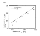
- Fig. 12 is a graph showing the temperature dependency of the electromotive force of the oxygen gas concentration cell.
- Fig. 13 is a graph showing changes of the electromotive force of the oxygen gas concentration cell as time advances when the oxygen concentration was changed at a low temperature of 250°C.
- the oxygen concentration was raised in a stepwise manner in the range 10% ⁇ 100%, and then when it was lowered in a stepwise manner, an electromotive force was obtained in accordance with the oxygen concentration, and that electromotive force was shown to match the theoretical value for the most part.
- Fig. 14 is a graph showing the relationship between the oxygen partial pressure and the electromotive force at 250°C.
- the electromotive force was measured as being low by a fixed proportion, and the electromotive force changed in accordance with the oxygen partial pressure. This profile is similar to the theoretical value and shows linear changes. From Fig. 12, Fig. 13 and Fig. 14, it was shown that the solid electrolyte sensor in which the particle-dispersed complex of Example 4 is made an electrode can detect oxygen concentration at a low temperature of 250°C, which has not occurred up to this point. Further, the response time of the electrode at 227°C was 900 seconds.
- Example 4 Because ruthenium system fine particles are dispersed in a carbon matrix without aggregation, the ruthenium particles are highly active, and in the case where the electrode formed from the particle-dispersed complex of the examples is used as an electrode of an oxygen sensor or a solid electrolyte fuel cell, even the slightest of oxygen ion movement will be picked out as a signal, whereby operations at low temperature are possible.
- the electrode formed from the particle-dispersed complex of the examples is used as an electrode of an oxygen sensor or a solid electrolyte fuel cell, even the slightest of oxygen ion movement will be picked out as a signal, whereby operations at low temperature are possible.
- the electrode formed from the particle-dispersed complex of the examples is used as an electrode of an oxygen sensor or a solid electrolyte fuel cell, even the slightest of oxygen ion movement will be picked out as a signal, whereby operations at low temperature are possible.
- the electrode formed from the particle-dispersed complex of the examples is used as an electrode of an oxygen
- it can be used as an electrode of an exhaust gas sensor of an automobile or the like which is a limiting current method sensor. Furthermore, it can be used as an electrode of an oxygen sensor in molten metal, in particular an oxygen sensor in molten metal which contains lead, bismuth.
Landscapes
- Chemical & Material Sciences (AREA)
- Life Sciences & Earth Sciences (AREA)
- Health & Medical Sciences (AREA)
- Electrochemistry (AREA)
- Chemical Kinetics & Catalysis (AREA)
- General Physics & Mathematics (AREA)
- Pathology (AREA)
- Analytical Chemistry (AREA)
- Biochemistry (AREA)
- General Health & Medical Sciences (AREA)
- Molecular Biology (AREA)
- Immunology (AREA)
- Physics & Mathematics (AREA)
- Engineering & Computer Science (AREA)
- Materials Engineering (AREA)
- General Chemical & Material Sciences (AREA)
- Crystallography & Structural Chemistry (AREA)
- Nanotechnology (AREA)
- Inert Electrodes (AREA)
- Measuring Oxygen Concentration In Cells (AREA)
Applications Claiming Priority (2)
| Application Number | Priority Date | Filing Date | Title |
|---|---|---|---|
| JP2004045325A JP3624196B1 (ja) | 2004-02-20 | 2004-02-20 | 粒子分散複合物及びそれを用いた固体電解質型センサー |
| PCT/JP2004/013561 WO2005080955A1 (ja) | 2004-02-20 | 2004-09-16 | 粒子分散複合物及びそれを用いた固体電解質型センサー |
Publications (2)
| Publication Number | Publication Date |
|---|---|
| EP1720009A1 true EP1720009A1 (de) | 2006-11-08 |
| EP1720009A4 EP1720009A4 (de) | 2008-12-17 |
Family
ID=34373675
Family Applications (1)
| Application Number | Title | Priority Date | Filing Date |
|---|---|---|---|
| EP04821688A Withdrawn EP1720009A4 (de) | 2004-02-20 | 2004-09-16 | Teilchendispergierter komplex und diesen verwendender elektrolytischer feststoffsensor |
Country Status (6)
| Country | Link |
|---|---|
| US (1) | US8043491B2 (de) |
| EP (1) | EP1720009A4 (de) |
| JP (1) | JP3624196B1 (de) |
| KR (1) | KR101146549B1 (de) |
| CN (1) | CN1918469B (de) |
| WO (1) | WO2005080955A1 (de) |
Family Cites Families (21)
| Publication number | Priority date | Publication date | Assignee | Title |
|---|---|---|---|---|
| JPH088989B2 (ja) * | 1987-06-22 | 1996-01-31 | 田中貴金属工業株式会社 | 貴金属炭素触媒の製造方法 |
| US5314727A (en) * | 1992-07-28 | 1994-05-24 | Minnesota Mining & Mfg. Co./Regents Of The University Of Minnesota | Chemical vapor deposition of iron, ruthenium, and osmium |
| US5543239A (en) * | 1995-04-19 | 1996-08-06 | Electric Power Research Institute | Electrode design for solid state devices, fuel cells and sensors |
| JP3377016B2 (ja) * | 1996-01-26 | 2003-02-17 | 矢崎総業株式会社 | 排気ガス中の酸素濃度測定用限界電流式酸素センサ |
| US6471745B1 (en) * | 1996-06-28 | 2002-10-29 | University Of Delaware | Nanoporous carbon catalytic membranes and method for making the same |
| US6303011B1 (en) * | 1997-06-23 | 2001-10-16 | Kabushiki Kaisha Riken | Gas sensor |
| US6811612B2 (en) * | 2000-01-27 | 2004-11-02 | The University Of Chicago | Patterning of nanocrystalline diamond films for diamond microstructures useful in MEMS and other devices |
| JP4479039B2 (ja) * | 2000-03-03 | 2010-06-09 | パナソニック株式会社 | 電気化学デバイス |
| US6669996B2 (en) * | 2000-07-06 | 2003-12-30 | University Of Louisville | Method of synthesizing metal doped diamond-like carbon films |
| JP4607303B2 (ja) | 2000-09-13 | 2011-01-05 | 株式会社フルヤ金属 | 金属電極から白金族金属を回収する方法 |
| US6562747B2 (en) * | 2000-12-19 | 2003-05-13 | Delphi Technologies, Inc. | Gas sensor electrolyte |
| KR100727372B1 (ko) * | 2001-09-12 | 2007-06-12 | 토소가부시키가이샤 | 루테늄착체, 그 제조방법 및 박막의 제조방법 |
| CN1226086C (zh) * | 2001-12-11 | 2005-11-09 | 中国科学院大连化学物理研究所 | 一种担载型金属催化剂及其制备方法 |
| JP2003187851A (ja) | 2001-12-21 | 2003-07-04 | Toyota Central Res & Dev Lab Inc | 固体高分子型燃料電池、その燃料極触媒および固体高分子型燃料電池を用いた発電方法 |
| JP4327405B2 (ja) | 2002-03-22 | 2009-09-09 | 株式会社フルヤ金属 | 固体電解質用電極の製造方法 |
| JP2003317728A (ja) | 2002-04-26 | 2003-11-07 | Ube Ind Ltd | 多孔質炭素フィルムを用いた燃料電池用電極、膜−電極接合体及び燃料電池 |
| US6682640B2 (en) * | 2002-06-13 | 2004-01-27 | Delphi Technologies, Inc. | Co-fired oxygen sensor elements |
| JP4917244B2 (ja) * | 2002-07-19 | 2012-04-18 | 株式会社フルヤ金属 | 固体電解質用電極、その製造方法、その使用方法並びに固体電解質型酸素センサー及び排ガスセンサー |
| KR100759547B1 (ko) | 2002-07-29 | 2007-09-18 | 삼성에스디아이 주식회사 | 연료전지용 탄소나노튜브, 그 제조방법 및 이를 채용한연료전지 |
| US7097875B2 (en) * | 2002-12-19 | 2006-08-29 | Delphi Technologies, Inc | Methods of making gas sensors and sensors formed therefrom |
| CN1150998C (zh) * | 2002-12-27 | 2004-05-26 | 浙江大学 | 在碳纳米管表面负载铂-钌合金纳米粒子的方法 |
-
2004
- 2004-02-20 JP JP2004045325A patent/JP3624196B1/ja not_active Expired - Fee Related
- 2004-09-16 KR KR1020067016590A patent/KR101146549B1/ko not_active Expired - Fee Related
- 2004-09-16 EP EP04821688A patent/EP1720009A4/de not_active Withdrawn
- 2004-09-16 US US10/590,079 patent/US8043491B2/en not_active Expired - Fee Related
- 2004-09-16 CN CN2004800418322A patent/CN1918469B/zh not_active Expired - Fee Related
- 2004-09-16 WO PCT/JP2004/013561 patent/WO2005080955A1/ja not_active Ceased
Also Published As
| Publication number | Publication date |
|---|---|
| CN1918469A (zh) | 2007-02-21 |
| JP3624196B1 (ja) | 2005-03-02 |
| US8043491B2 (en) | 2011-10-25 |
| WO2005080955A1 (ja) | 2005-09-01 |
| KR20070022213A (ko) | 2007-02-26 |
| JP2005233851A (ja) | 2005-09-02 |
| CN1918469B (zh) | 2010-05-26 |
| EP1720009A4 (de) | 2008-12-17 |
| US20070170399A1 (en) | 2007-07-26 |
| KR101146549B1 (ko) | 2012-05-25 |
Similar Documents
| Publication | Publication Date | Title |
|---|---|---|
| Wang et al. | Nano-metal diborides-supported anode catalyst with strongly coupled TaOx/IrO2 catalytic layer for low-iridium-loading proton exchange membrane electrolyzer | |
| Kwak et al. | In situ synthesis of supported metal nanocatalysts through heterogeneous doping | |
| EP2945909B1 (de) | Kern-hülle-katalysator enthaltend mischmetalloxidmaterial aus zinn und titan | |
| Chouki et al. | Solvothermal synthesis of iron phosphides and their application for efficient electrocatalytic hydrogen evolution | |
| Ma et al. | Greatly enhanced CO2 electrocatalytic reduction performance of Ag2Se nanocatalyst via phase-engineering | |
| Lim et al. | Atomic layer deposition of Pt@ CsH2PO4 for the cathodes of solid acid fuel cells | |
| Wain-Martin et al. | Scalable synthetic method for SOFC compounds | |
| Kimura et al. | Oxygen evolution behavior of La1− x Sr x FeO3− δ electrodes in LiCl–KCl melt | |
| Taninouchi et al. | High oxide-ion conductivity of monovalent-metal-doped bismuth vanadate at intermediate temperatures | |
| Bicer et al. | Electrochemical synthesis of CdS nanowires by underpotential deposition in anodic alumina membrane templates | |
| US8043491B2 (en) | Particle-dispersed complex and solid electrolytic sensor using it | |
| Sata et al. | Hydrogen spillover phenomenon: Enhanced reversible hydrogen adsorption/desorption at Ta2O5-coated Pt electrode in acidic media | |
| González-Cobos et al. | Electrochemical activation of Au nanoparticles for the selective partial oxidation of methanol | |
| JP5207461B2 (ja) | 電極触媒及びそれを用いた電極 | |
| Goto et al. | Electrochemical properties of iridium-carbon nano composite films prepared by MOCVD | |
| Mahesh et al. | Efficient electrooxidation of ethanol on Bi@ Pt/C nanoparticles:(i) Effect of monolayer Bi deposition on specific sites of Pt nanoparticle (ii) Calculation of average number of es without help of chemical analysis | |
| Randin | Electrochemical deposition of sodium tungsten bronzes | |
| JP4917244B2 (ja) | 固体電解質用電極、その製造方法、その使用方法並びに固体電解質型酸素センサー及び排ガスセンサー | |
| Nur’aini et al. | An investigation of non-noble metal electrodes for carbon dioxide electrolysis in molten lithium carbonate | |
| Massot et al. | Comparison between derived Sol-Gel and conventional methods for the preparation of dimensionally stable Ta/IrO2 anodes for oxygen evolution | |
| Han et al. | Al-modified Pb-Ag anode alloy with enhanced corrosion resistance and reduced overpotential | |
| Bergmann et al. | Kinetic studies on electrochemical antimony removal from concentrated sulfuric acid systems | |
| EP4495290A1 (de) | Elektrode, elektrolyseur, herstellungsverfahren und verwendung der elektrode | |
| JP5393538B2 (ja) | 固体電解質型酸素センサー及び排ガスセンサー | |
| Shapoval et al. | Physicochemical properties of tungsten carbide powders prepared from ionic melts |
Legal Events
| Date | Code | Title | Description |
|---|---|---|---|
| PUAI | Public reference made under article 153(3) epc to a published international application that has entered the european phase |
Free format text: ORIGINAL CODE: 0009012 |
|
| 17P | Request for examination filed |
Effective date: 20060905 |
|
| AK | Designated contracting states |
Kind code of ref document: A1 Designated state(s): AT BE BG CH CY CZ DE DK EE ES FI FR GB GR HU IE IT LI LU MC NL PL PT RO SE SI SK TR |
|
| DAX | Request for extension of the european patent (deleted) | ||
| A4 | Supplementary search report drawn up and despatched |
Effective date: 20081119 |
|
| 17Q | First examination report despatched |
Effective date: 20090213 |
|
| GRAP | Despatch of communication of intention to grant a patent |
Free format text: ORIGINAL CODE: EPIDOSNIGR1 |
|
| INTG | Intention to grant announced |
Effective date: 20140218 |
|
| RIN1 | Information on inventor provided before grant (corrected) |
Inventor name: SUZUKI, HAJIME Inventor name: JINUSHI, KEIICHIRO Inventor name: KIMURA, TEIICHI Inventor name: GOTO, TAKASHI |
|
| STAA | Information on the status of an ep patent application or granted ep patent |
Free format text: STATUS: THE APPLICATION IS DEEMED TO BE WITHDRAWN |
|
| 18D | Application deemed to be withdrawn |
Effective date: 20140701 |