EP1719980B1 - Ultrasonic flowmeter and ultrasonic flow rate measurement method - Google Patents
Ultrasonic flowmeter and ultrasonic flow rate measurement method Download PDFInfo
- Publication number
- EP1719980B1 EP1719980B1 EP05719456.5A EP05719456A EP1719980B1 EP 1719980 B1 EP1719980 B1 EP 1719980B1 EP 05719456 A EP05719456 A EP 05719456A EP 1719980 B1 EP1719980 B1 EP 1719980B1
- Authority
- EP
- European Patent Office
- Prior art keywords
- flow rate
- unit
- transducer
- pipe
- measurement
- Prior art date
- Legal status (The legal status is an assumption and is not a legal conclusion. Google has not performed a legal analysis and makes no representation as to the accuracy of the status listed.)
- Active
Links
- 238000000691 measurement method Methods 0.000 title claims description 18
- 238000000034 method Methods 0.000 claims description 242
- 238000005259 measurement Methods 0.000 claims description 166
- 230000005540 biological transmission Effects 0.000 claims description 100
- 239000012530 fluid Substances 0.000 claims description 68
- 238000004364 calculation method Methods 0.000 claims description 46
- 238000006243 chemical reaction Methods 0.000 claims description 13
- 230000003321 amplification Effects 0.000 claims description 8
- 238000003199 nucleic acid amplification method Methods 0.000 claims description 8
- 238000001514 detection method Methods 0.000 description 26
- 238000010586 diagram Methods 0.000 description 26
- 238000012545 processing Methods 0.000 description 23
- 238000011144 upstream manufacturing Methods 0.000 description 20
- 230000014509 gene expression Effects 0.000 description 15
- 230000008859 change Effects 0.000 description 9
- 238000009826 distribution Methods 0.000 description 7
- 230000004044 response Effects 0.000 description 5
- 239000012535 impurity Substances 0.000 description 4
- 238000009434 installation Methods 0.000 description 4
- 238000005070 sampling Methods 0.000 description 4
- 238000007796 conventional method Methods 0.000 description 3
- 230000006872 improvement Effects 0.000 description 3
- 230000000977 initiatory effect Effects 0.000 description 3
- 238000004519 manufacturing process Methods 0.000 description 3
- 230000010355 oscillation Effects 0.000 description 3
- 230000009467 reduction Effects 0.000 description 3
- 230000006870 function Effects 0.000 description 2
- 238000003780 insertion Methods 0.000 description 2
- 230000037431 insertion Effects 0.000 description 2
- 230000008569 process Effects 0.000 description 2
- 230000001902 propagating effect Effects 0.000 description 2
- 239000002131 composite material Substances 0.000 description 1
- 230000003111 delayed effect Effects 0.000 description 1
- 230000010354 integration Effects 0.000 description 1
- 239000000463 material Substances 0.000 description 1
- 230000003252 repetitive effect Effects 0.000 description 1
- 230000000153 supplemental effect Effects 0.000 description 1
- 238000002604 ultrasonography Methods 0.000 description 1
- XLYOFNOQVPJJNP-UHFFFAOYSA-N water Substances O XLYOFNOQVPJJNP-UHFFFAOYSA-N 0.000 description 1
- 230000010356 wave oscillation Effects 0.000 description 1
Images


Classifications
-
- G—PHYSICS
- G01—MEASURING; TESTING
- G01F—MEASURING VOLUME, VOLUME FLOW, MASS FLOW OR LIQUID LEVEL; METERING BY VOLUME
- G01F1/00—Measuring the volume flow or mass flow of fluid or fluent solid material wherein the fluid passes through a meter in a continuous flow
- G01F1/66—Measuring the volume flow or mass flow of fluid or fluent solid material wherein the fluid passes through a meter in a continuous flow by measuring frequency, phase shift or propagation time of electromagnetic or other waves, e.g. using ultrasonic flowmeters
- G01F1/663—Measuring the volume flow or mass flow of fluid or fluent solid material wherein the fluid passes through a meter in a continuous flow by measuring frequency, phase shift or propagation time of electromagnetic or other waves, e.g. using ultrasonic flowmeters by measuring Doppler frequency shift
-
- G—PHYSICS
- G01—MEASURING; TESTING
- G01F—MEASURING VOLUME, VOLUME FLOW, MASS FLOW OR LIQUID LEVEL; METERING BY VOLUME
- G01F1/00—Measuring the volume flow or mass flow of fluid or fluent solid material wherein the fluid passes through a meter in a continuous flow
- G01F1/66—Measuring the volume flow or mass flow of fluid or fluent solid material wherein the fluid passes through a meter in a continuous flow by measuring frequency, phase shift or propagation time of electromagnetic or other waves, e.g. using ultrasonic flowmeters
- G01F1/662—Constructional details
-
- G—PHYSICS
- G01—MEASURING; TESTING
- G01F—MEASURING VOLUME, VOLUME FLOW, MASS FLOW OR LIQUID LEVEL; METERING BY VOLUME
- G01F1/00—Measuring the volume flow or mass flow of fluid or fluent solid material wherein the fluid passes through a meter in a continuous flow
- G01F1/66—Measuring the volume flow or mass flow of fluid or fluent solid material wherein the fluid passes through a meter in a continuous flow by measuring frequency, phase shift or propagation time of electromagnetic or other waves, e.g. using ultrasonic flowmeters
- G01F1/667—Arrangements of transducers for ultrasonic flowmeters; Circuits for operating ultrasonic flowmeters
-
- G—PHYSICS
- G01—MEASURING; TESTING
- G01F—MEASURING VOLUME, VOLUME FLOW, MASS FLOW OR LIQUID LEVEL; METERING BY VOLUME
- G01F7/00—Volume-flow measuring devices with two or more measuring ranges; Compound meters
Definitions
- the present invention relates to an ultrasonic flowmeter for measuring a flow rate of a fluid by emitting an ultrasonic wave into the fluid as the subject of measurement, and in particular to an ultrasonic flowmeter and ultrasonic flow rate measurement method effectively applicable to a flow rate measurement of diverse kinds of fluid, et cetera.
- This method is capable of a high precision and high speed response, and has excellent anti-bubble qualities.
- the method is faced with a technical problem of incapability of measuring a fluid with a small amount of impurities and of a limitation of a measurable velocity range.
- V MAX the maximum measurable velocity range. That is, the maximum measurable velocity V MAX is expressed by: [Expression 2] V MAX ⁇ C f 2 / 8 ⁇ D ⁇ f 0 ⁇ sin ⁇ f where C f is the sonic velocity of a fluid, D is the inner diameter of the pipe, and f 0 is the transmission frequency of an ultrasonic wave.
- a patent document 3 has disclosed a method for making two divided distributions, by dividing a measured velocity distribution into two at the center of the flowing fluid section and acquiring a flow velocity of the entire flowing fluid section by folding one of the divided distributions with a smaller fluctuation.
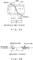
- the transit time method is a method which employs a pair of detectors integrated with transmitter/receiver as shown by Fig. 2A , and compares an ultrasonic transmission time T1 (refer to Fig. 2B ) from the upstream to downstream side with an ultrasonic transmission time T2 (refer to Fig. 2C ) from the downstream to upstream side and acquires the average flow velocity V and flow rate Q according to the expressions (6) and (7).
- V t D sin 2 ⁇ f ⁇ T T 0 ⁇ ⁇ 2
- Q ⁇ 4 D 2 ⁇ 1 K ⁇ V t
- ⁇ T T2-T1
- D pipe diameter
- ⁇ f angle of incidence of ultrasonic wave into a fluid
- ⁇ a propagation time in a pipe wall and wedge
- K a conversion coefficient for the average flow velocity.
- the method has problems, such as a low accuracy, a slow response and a vulnerability to bubbles or impurities, as compared to the above described pulse Doppler method, it has advantages such as the capability of measurement of a fluid without bubbles or impurities, and an absence of a limitation of a measurable range contrary to the pulse Doppler method.
- a pair of multi-frequency ultrasound transducer surround a fluid flow and are configured to operate under computer control in both a mono-static and a bi-static mode at each of themultiplefrequencies.
- the mono-static mode pulsed wideband Doppler shift measurements provide the velocity profile across the fluid flow which can be combined with measured pressure drops to determine the rheogram-a plot of shear stress versus shear rate.
- Velocity profile data from each frequency can be combined to form a composite velocity profile.
- transmission data is collected that improves the accuracy and robustness of the velocity profile and provides supplemental material property information.
- the system is configured for automated operation for a wide variety of fluid types and can be reconfigured and/or monitored remotely.
- a purpose of the present invention is to provide an ultrasonic flowmeter and ultrasonic flow rate measurement method which are capable of improving measurement accuracy and a measurable range without being influenced by the state of a fluid such as a flow velocity and an amount of bubbles.
- Another purpose of the present invention is to accomplish a reduction of production cost and simplification of installing a detector for an ultrasonic flowmeter.
- Still another purpose of the present invention is to provide a flow rate measurement method and apparatus which are capable of measuring a flow rate with high accuracy across a wide range of velocity by switching between two measurement methods, i.e., the pulse Doppler method and the transit time method, according to a condition, such as a flow velocity profile or an amount of bubbles of a fluid as the subject of measurement.
- an ultrasonic flow rate measurement method as set out in claim 4.
- a first aspect of the disclosure is an ultrasonic flowmeter comprising a plurality of flow rate measurement units for measuring a flow rate of a fluid in a pipe by using an ultrasonic wave in mutually different measurement principles.
- a second aspect of the disclosure is an ultrasonic flowmeter comprising: a plurality of flow rate measurement units for measuring a flow rate of a fluid in a pipe by mutually different measurement principles using an ultrasonic wave; and a transducer unit for carrying out an interconversion between an acoustic signal and electric signal by being mounted onto the pipe and being shared among a plurality of the flow rate measurement units.
- a third aspect of the disclosure is an ultrasonic flowmeter comprising: a first flow rate measurement unit for detecting a flow rate of a fluid in a pipe by using a transit time method; a second flow rate measurement unit for detecting a flow rate of a fluid in the pipe by using a pulse Doppler method; a plurality of first and second transducer units, being mounted onto the pipe in which a fluid as the subject of measurement flows through, each of which carries out an interconversion between an acoustic signal and electric signal; and a transducer changeover unit for making the first and second flow rate measurement units share the transducer unit.
- a fourth aspect of the disclosure is an ultrasonic flow rate measurement method for measuring a flow rate of a fluid within a pipe by using an ultrasonic wave, measuring a flow rate by a plurality of flow rate measurement units, which use respectively different measurement principles, sharing a plurality of transducer units, each of which, being mounted onto the pipe, carries out an interconversion between an acoustic signal and an electric signal, and changing over a connection of the transducer unit for each of the flow rate measurement units.
- a plurality of said flow rate measurement units for example may be configured to include a first flow rate measurement unit for detecting a flow rate of a fluid within said pipe by using a transit time method and a second flow rate measurement unit for detecting a flow rate of the fluid within the pipe by using a pulse Doppler method.
- a detector changeover unit maybe equipped which allows an operation by at least one detector, so as to enable the pulse Doppler method to use at least one of a pair of detectors for use in the transit time method which requires two detectors.
- a configuration may be such that a pair of detectors can be placed on the mutually opposite sides across the axis of a pipe and at mutually displaced positions in the direction of the flow of a fluid, or may also be such that a pair of detectors can be placed on the same side of a pipe and at mutually separated positions in the direction of the flow of a fluid.
- the ultrasonic flowmeter comprises the first flow rate measurement unit and the second flow rate measurement unit with different measurement principles for using them either mutually independently or both simultaneously, thereby making it possible to measure a flow rate of a fluid over a wide range and with high accuracy without an influence of various states of the fluid as the subject of measurement such as a velocity and bubbles by mutually complementing a shortcoming of the other method.
- a common use of a pair of detectors for a measurement by the pulse Doppler method and a combination with a measurement result using the both detectors makes it possible to improve the measurement accuracy of a flow rate by preventing a degraded measurement accuracy close to the pipe wall on the installed side, in the case of using a single detector while suppressing a cost increase.
- a fifth aspect of the disclosure is an ultrasonic flowmeter capable of measuring a flow rate by the pulse Doppler method and the transit time method simultaneously in parallel.
- the present flowmeter comprises at least one pair of electric/ultrasonic transducers necessary for measuring a flow rate by a transit time method; a hardware unit (e.g., consisting of a transmission & receiving time control unit and pulse generator) for providing at least one pair of electric/ultrasonic transducers with a pulse signal necessary for measuring a flow rate by the pulse Doppler method and necessary for measuring a flow rate by the transit time method; a detection circuit for detecting a Doppler frequency shift from a received signal obtained from a discretionary transducer including the one pair of electric/ultrasonic transducers; a conversion circuit for amplifying and analog/digital-converting a first received signal obtained by an ultrasonic pulse transmission from the upstream to the downstream, and a second received signal obtained by an ultrasonic pulse transmission from the downstream to the upstream, both by the one pair of
- a later described fourth embodiment is configured to further comprise a second electric/ultrasonic transducer used only for measuring a flow rate by a pulse Doppler method, wherein the hardware unit provides both the one pair of electric/ultrasonic transducers and the second electric/ultrasonic transducer with a transmission pulse signal, and the detection circuit detects the Doppler frequency shift from a received signal obtained from the second electric/ultrasonic transducer.
- a later described fifth embodiment is configured such that the at least one pair of electric/ultrasonic transducers is one pair only, and the ultrasonic flow rate meter further comprises a switch unit, being inserted between an input of a pulse signal output and the conversion unit of the hardware unit for a Doppler method and one transducer of the one pair only electric/ultrasonic transducers, for connecting a circuit only for a measuring period by the pulse Doppler method, wherein the detection circuit detects the Doppler frequency shift from a received signal which is an echo of an ultrasonic pulse output from the one transducer.
- the configuration may be such that the control unit and hardware unit collaborate in changing flow rate measurement modes, i.e., a pulse Doppler method, a transit time method and a simultaneous use of both methods, according to an external command or signal.
- changing flow rate measurement modes i.e., a pulse Doppler method, a transit time method and a simultaneous use of both methods, according to an external command or signal.
- a fifth aspect of the disclosure is an ultrasonic flowmeter capable of carrying out a flow rate measurement by changing over between a pulse Doppler method and a transit time method.
- the present ultrasonic flowmeter comprises at least one pair of electric/ultrasonic transducers necessary for measuring a flow rate by a transit time method; a pulse generation unit, comprising a single output terminal, for providing the one pair of electric/ultrasonic transducers with a pulse signal, from the aforementioned terminal, necessary for measuring a flow rate by the transit time method, and to generate and output a pulse signal to one of the one pair of electric/ultrasonic transducers, necessary for measuring a flow rate by the pulse Doppler method; a detection circuit for detecting a Doppler frequency shift necessary for calculating a flow rate by the pulse Doppler method by using one discretionary transducer including the one pair of electric/ultrasonic transducers; a changeover unit (i.e., the transmission & receiving timing control unit) for enabling an amplification
- a detection circuit is configured to comprise an amplifier at a front stage thereof and one pair of analog/digital converters for processing a real part of data and an imaginary part of data respectively at a rear stage
- the changeover unit comprises one pair of single-pole dual-throw switch units, being inserted immediately before the one pair of analog/digital converters, for connecting a circuit only for a measurement period of a pulse Doppler method, while connecting an output of the amplifier to one input of the one pair of analog/digital converters, and further comprises a second switch unit whose common terminal is connected to an output terminal of the pulse generation unit and an input terminal of the detection circuit, and one pair of contacts of which is connected to the single pair of electric/ultrasonic transducers
- the changeover unit controls change over between the first pair of switch units and the second single-pole dual-throw switch unit for connecting an output of the amplifier to one of the transducers during a measurement period for the pulse Doppler method and changing over to the second switch unit during a measurement period for
- the configuration is such that the at least one pair of electric/ultrasonic transducers are a plurality of pairs of transducers, a second switch unit is a single-pole switch comprising two times the plural number of contacts which are connected to the plural pairs of transducers one by one, and the changeover unit allocates a measurement period of a pulse Doppler method and that of a transit time method to each pair of the plural pairs of transducers and, for the each pair, changes over the second switch unit so that an input of the amplifier is connected to one of the applicable pair of transducers during a measurement period of the pulse Doppler method, while the amplifier is connected to the applicable pair of transducers for a measurement period of the transit time method according to a measurement algorithm thereof.
- the configuration may be such that the control unit and the changeover unit collaborate in changing flow rate measurement modes, i.e., a pulse Doppler method, a transit time method and a simultaneous use of both methods, according to an external command or signal.
- changing flow rate measurement modes i.e., a pulse Doppler method, a transit time method and a simultaneous use of both methods, according to an external command or signal.
- Fig. 3 is a conceptual diagram exemplifying a comprisal of an ultrasonic flowmeter for carrying out an ultrasonic flow rate measurement method according to an embodiment of the disclosure.
- the ultrasonic flowmeter being mounted onto a pipe 50 in which a fluid 51 as the subject of measurement flows, comprises a plurality of detectors 41, 42 and 43 (i.e., the transducer units) comprising a piezoelectric element, et cetera, each of which functions as an ultrasonic transmitter & receiver.
- each of the detectors 41, 42 and 43 comprises a piezoelectric element 40a for carrying out an interconversion between an acoustic signal, such as an ultrasonic oscillation, and electric signal and a wedge body 40b, lying between the wedge body 40b and the outer wall surface of the pipe 50, for transmitting an ultrasonic oscillation generated by the piezoelectric element 40a into the pipe 50 at a predetermined incidence angle to transmit the ultrasonic oscillation of the side of the pipe 50 to the piezoelectric element 40a, for example as shown by Fig. 7 .
- the detector 43 is installed so that the emitting path of its ultrasonic wave through the center axis of the pipe 50 is in a direction slanting toward the downstream when viewed from the installed position of the detector 43.
- the pair of detectors 41 and 42 is connected to the applicable detector changeover switch 15, received signal amplification control unit 11, A/D converter 12, propagation time calculation unit 13, flow rate calculation unit 14 and a transit time method unit 10 (i.e., a first flow rate measurement unit) which is comprised of a transmission pulse generation unit 31 and transmission & reception time control unit 32 by way of a detector changeover switch 15.
- a transit time method unit 10 i.e., a first flow rate measurement unit
- the transit time method unit 10 (1) generates an ultrasonic wave oscillation by applying a transmission pulse power, which is output from the transmission pulse generation unit 31 synchronously with a transmission initiation signal 32a output from the transmission & reception time control unit 32, to one detector 41 by way of the detector changeover switch 15; which is (2) immediately followed by changing over the detector changeover switch 15 to the detector 42 side, receiving an ultrasonic wave arriving thereat, converting it into an electric signal, inputting it to the received signal amplification control unit 11 for amplification, further followed by the A/D converter 12 converting the received signal to digital synchronously with an A/D sampling clock 32b which is output from the transmission & reception time control unit 32 and inputting it to the propagation time calculation unit 13.
- the aforementioned operations (1) and (2) are carried out alternately by changeover operations of the applicable detector changeover switch 15 changing over between a transmission and a reception side of the detectors 41 and 42.
- the detector 43 is connected to a received signal amplification control unit 21, A/D converter 22, flow velocity profile calculation unit 23, integral calculation unit 24 and pulse Doppler method unit 20 (i.e., a second flow rate measurement unit) comprised of the transmission pulse generation unit 31 and transmission & reception time control unit 32 which are common to the transit time method unit 10.
- a received signal amplification control unit 21 A/D converter 22, flow velocity profile calculation unit 23, integral calculation unit 24 and pulse Doppler method unit 20 (i.e., a second flow rate measurement unit) comprised of the transmission pulse generation unit 31 and transmission & reception time control unit 32 which are common to the transit time method unit 10.
- the transmission pulse generation unit 31 and transmission & reception time control unit 32 which are equipped commonly to the transit time method unit 10 and pulse Doppler method unit 20, as is the measurement value output changeover switch 34, are controlled so as to determine which of the operations is to be carried out, that is, for the above described transit time method unit 10 or pulse Doppler method unit 20 by an output selection signal 33a and measurement method selection signal 33b which are output from a measurement method changeover control unit 33.
- measurement state data 13a and the measurement state data 23a which are output from the propagation time calculation unit 13 comprised by the transit time method unit 10 and the flow velocity profile calculation unit 23 comprised by the pulse Doppler method unit 20, respectively, are input to the measurement method changeover control unit 33 which then judges whether the transit time method unit 10, pulse Doppler method unit 20, or both, is to operate based on the data.
- the present embodiment is configured to measure a flow rate of the fluid 51 within the pipe 50 by changing over between the transit time method unit 10 and pulse Doppler method unit 20 by the measurement method changeover control unit 33 controlling the transit time method unit 10 and pulse Doppler method unit 20, and further the measurement value output changeover switch 34, while making judgment of operating conditions of the transit time method unit 10 and pulse Doppler method unit 20 based on information such as the measurement state data 13a and the measurement state data 23a. Therefore, it is possible to measure a flow rate over a limitlessly wide range of measurement and with high accuracy by employing the respective advantages of the transit time method unit 10 and pulse Doppler method unit 20.
- the transit time method unit 10 is initiated and at the same time an output of the measurement value output changeover switch 34 is changed over to the transit time method unit 10, thereby enabling a continuation of the measurement.
- the measurement method changeover control unit 33 determines a state of the fluid 51 within the pipe 50 from each measurement result based on the measurement state data 13a and the measurement state data 23a and changes over to a suitable method among a parallel operation of the transit time method unit 10 and pulse Doppler method unit 20, the former method only or the latter method only by a changeover control to the transmission pulse generation unit 31 and transmission & reception time control unit 32 by the output selection signal 33a and a change control of the measurement value output changeover switch 34 by the measurement method selection signal 33b, thereby making it possible to accomplish a high measurement accuracy for a wide measurement range without an influence of a state of a fluid.
- Fig. 4 is a conceptual diagram exemplifying a comprisal of an ultrasonic flowmeter according to an embodiment of the present invention.
- the comprisal shown by Fig. 4 exemplifies the case of placing a detector changeover switch 35 at the front stage of the received signal amplification control unit 21 comprised by the pulse Doppler method unit 20 and sharing both of a pair of detector 41 (i.e., a first transducer unit) and detector 42 (i.e., a second transducer unit) with the pulse Doppler method unit 20 in the comprisal shown by the above described Fig. 3 .
- detector 41 i.e., a first transducer unit
- detector 42 i.e., a second transducer unit
- the example comprisal shown by Fig. 4 reduces the number of detectors from three to two from that of the Fig. 3 by eliminating the detector 43 dedicated to the pulse Doppler method unit 20 as a result of sharing either one or both of the pair of detectors 41 and 42 used by the transit time method unit 10 by connecting the pair thereof to the pulse Doppler method unit 20 by way of the detector changeover switch 35.
- a pair of the detectors 41 and 42 is mounted on mutually opposite sides across the center axis of the pipe 50 and displaced toward the upstream and the downstream, with each being positioned on the path of the ultrasonic wave emitted from the other of the detectors 41 and 42 as exemplified by Fig. 4 .
- a flow velocity profile calculation part comprises a flow velocity profile calculation unit 23-1 for calculating a flow velocity profile (i.e., the left half of Fig. 5 ) detected by connecting the detector changeover switch 35 to the side of detector 41, a flow velocity profile calculation unit 23-2 for calculating a flow velocity profile (i.e., the right half of Fig. 5 ) detected by connecting the detector changeover switch 35 to the side of detector 42 and an input changeover switch 23-3 for changing over between the flow velocity profile calculation unit 23-1 and flow velocity profile calculation unit 23-2 by a selection signal 32d from the transmission & reception time control unit 32 by linking with the changeover operation of the detector changeover switch 35.
- a flow velocity profile calculation unit 23-1 for calculating a flow velocity profile (i.e., the left half of Fig. 5 ) detected by connecting the detector changeover switch 35 to the side of detector 41
- a flow velocity profile calculation unit 23-2 for calculating a flow velocity profile (i.e., the right half of Fig. 5 ) detected by connecting the
- This configuration measures a flow velocity profile 51a for the half of the cross section on the far side from the detector 41 by making the flow velocity profile calculation unit 23-1 operate in the state of connecting the pulse Doppler method unit 20 to the applicable detector 41, while measuring a flow velocity profile 51b for the half of the cross section on the far side from the detector 42 in the state of being connected to the applicable detector 42, and the integral calculation unit 24 at the later stage outputs a flow rate measurement value by calculating a flow rate based on a flow velocity profile 51c of the entire cross sectional area as a result of adding respective flow velocity profiles of the flow velocity profile calculation unit 23-1 (i.e., the detector 41) and flow velocity profile calculation unit 23-2 (i.e., the detector 42), as exemplified by Fig. 5 .
- the present embodiment shown by Figs. 4 and 5 makes the pulse Doppler method unit 20 side employing the pulse Doppler method share a pair of the detectors 41 and 42, which is necessary for the transit time method of the transit time method unit 10, by way of the detector changeover switch 35, thereby compensating for a degraded accuracy of a flow velocity profile measurement close to a detector, which is a technical problem of the pulse Doppler method in the case of using a single detector, by adding the measurement data of the detectors 41 and 42, hence accomplishing an improvement of a measurement accuracy.
- the transit time method unit 10 measure a flow rate distribution in parallel with a measurement processing of the pulse Doppler method unit 20 by receiving an acoustic signal by connecting the detector 42 (or the detector 41), which is not connected to the pulse Doppler method unit 20, to the transit time method unit 10 during a flow rate measurement by using the detector 41 (or the detector 42) of the aforementioned pulse Doppler method unit 20.
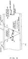
- Fig. 6 is a block diagram exemplifying a comprisal of an ultrasonic flowmeter according to another embodiment of the disclosure.
- Figs. 7 and 8 are conceptual diagrams describing example operations thereof.
- the embodiment shown by Fig. 6 is configured to place a detector 41 in the downstream of the axial direction on the same side of the pipe 50 and place a detector 42 in the upstream so that the propagation paths of ultrasonic waves emitted from the detectors 41 and 42 form a V shape as a result of being reflected by the wall on the other side of the center axis of the pipe 50 at the time of measurement by the transit time method unit 10.
- a placement method for detectors is summarily called a "V method.”
- the transit time method unit 10 causes the detector 41 to send out an ultrasonic wave and measure a flow velocity profile of the fluid 51 in the pipe 50 by detecting an acoustic signal incident on the other detector 42 after the ultrasonic wave is reflected by the wall surface on the other side.
- the pulse Doppler method unit 20 carries out a measurement operation of a flow velocity profile as described later by using the detectors 41 and 41 by way of the detector changeover switch 35.
- a flow velocity is acquired assuming the flow velocity V f (in the direction of flow) to be parallel with the axis of the pipe 50, and as such the Doppler shift frequency is f d ⁇ V f *sin ⁇ f , where the incident angle of an ultrasonic wave vis-à-vis the fluid 51 is ⁇ f as shown by Fig. 7 .
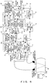
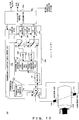
- Fig. 9 is a summary block diagram showing a comprisal of an ultrasonic flowmeter according to a fourth embodiment of the disclosure.
- an ultrasonic flowmeter 101 according to the present disclosure is capable of carrying out both flow rate measurement by the pulse Doppler method and the transit time method simultaneously in parallel by comprising both of a measurement system (110 plus 130) for the pulse Doppler method and that (111 plus 140) for the transit time method.
- the calculation control unit 150 sends a flow rate measurement start instruction MS to the transmission & reception timing control unit 120.
- the transmission & reception timing control unit 120 provides the transmission pulse generator 122 an instruction to transmit a pulse Doppler method measurement-use transmission pulse TD and a transit time method measurement-use first transmission pulse (i.e., a transmission pulse for providing to the upstream transducer 111u for example) TP1, and the transmission pulse generator 122 transmits and outputs a transmission pulses TD and TP1 immediately. This initiates a flow rate measurement by the pulse Doppler method and by the transit time method simultaneously.
- a flow rate calculation processing of the pulse Doppler method carried out by the Doppler frequency shift detection unit 130 and calculation control unit 150 may be carried out by any flow rate calculation method, including the conventional method and a flow rate calculation method which might be formulated in the future.
- a flow rate calculation processing of the transit time method carried out by the received signal processing unit 140 and calculation control unit 150 maybe carried out by any flow rate calculation method, including the conventional method and a flow rate calculation method which might be formulated in the future.
- a transmission pulse TD is applied to the transducer 110
- an ultrasonic signal is emitted into the pipe from the transducer 110
- an echo of the ultrasonic signal is converted into an electric signal by the transducer 110 and the electric signal is received therefrom as a received signal RD.
- the received signal RD is input to the Doppler frequency shift detection unit 130 for detecting a Doppler frequency shift.
- the calculation control unit 150 calculates a flow velocity profile and a flow rate based on the received data from the Doppler frequency shift detection unit 130.
- the next step is to connect the common terminal of the switch SW to the contact "a" (step 218) to cause the received signal processing unit 140 to sample and A/D-convert a received signal RP2 from the transducer 111u in a predetermined interval to hand the result over to the calculation control unit 150 (step 220).
- the calculation control unit 150 calculates a flow velocity and flow rate based on the received data from the received signal processing unit 140.
- the received signal RP1 sensed and converted by the downstream transducer 111d is supplied from the switch SW2 to an input terminal of the received signal processing unit 140 by way of the contact SW2b for use in a flow rate measurement by the transit time method.
- the received signal RP2 is supplied from the switch SW2 to an input terminal of the received signal processing unit 140 by way of the contact "a" of the switch SW2, and is used for a flow rate calculation of the transit time method together with the above described received signal RP1.
- the ultrasonic pulse output from the transducer 111d is scattered by bubbles, etcetera, within the fluid, with a part of the scattered ultrasonic wave returning to the transducer 111d as an echo which is then supplied to the Doppler frequency shift detection unit 130 by way of the contact "b" of the switch SW1 as an echo signal of the transmission pulse TD.
- a repetition of the above described measurement cycles for a predefined number of times carries out flow rate measurements by the pulse Doppler method and transit time method simultaneously in parallel.
- the Doppler frequency shift detection unit 130a is the same as the Doppler frequency shift detection unit 130 except for the insertion of a switch SW3 between the filter 133R and the A/D converter 134R and the insertion of a switch SW4 between the filter 133I and the A/D converter 134I.
- Fig. 15A is a summary block diagram showing a comprisal of an ultrasonic flowmeter according to an embodiment of the present invention.
- an ultrasonic flowmeter 104 according to the present embodiment is the same as the ultrasonic flowmeter 103 shown by Fig. 13 , except for the replacement of the transmission & reception timing control unit 120b by 120c and the switch SW1 by a six-contact single-pole switch SW1a, and the addition of the pairs of transducers 112 and 113.
- the description here only deals with the differences.
- the pairs of transducers 111, 112 and 113 are placed on the outer circumference of the pipe at approximately the same intervals.
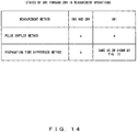
- a measurement by the transit time method only requires changing the both switches SW3 and SW4 over to "b".
- a circuit made up of the switch SW1-T, amplifier 131, switch SW4 and A/D converter 134I becomes the same as the circuit made up of the transducer 110 and Doppler frequency shift detection unit 130 shown by Fig. 9 demonstrating that a measurement by the transit time method is enabled.
- the same changeover control is carried out for the switch SW1-T as for the switch SW as shown by Fig. 10 (where the u and d for identifying contacts correspond to a and b respectively).
- the second embodiment is configured to measure by the pulse Doppler method an echo signal of the first transmission pulse of each measurement cycle by using the transducer 111u
- the present invention makes it possible to measure a flow rate of a fluid over a wide range and with a high accuracy without an influence by a state of the fluid such as the velocity and amount of bubbles.
Landscapes
- Physics & Mathematics (AREA)
- Fluid Mechanics (AREA)
- General Physics & Mathematics (AREA)
- Electromagnetism (AREA)
- Measuring Volume Flow (AREA)
Description
- The present invention relates to an ultrasonic flowmeter for measuring a flow rate of a fluid by emitting an ultrasonic wave into the fluid as the subject of measurement, and in particular to an ultrasonic flowmeter and ultrasonic flow rate measurement method effectively applicable to a flow rate measurement of diverse kinds of fluid, et cetera.
- A clamp-on type ultrasonic flowmeter for installing a detector on the outer wall of a pipe, emitting an ultrasonic wave into a fluid flowing in the pipe from the outside of the pipe, and measuring a flow rate on the inside of the pipe by measuring a change of the ultrasonic wave propagating within the fluid has many advantages such as an existing pipe not requiring specific installation work, and a minimal influence by the temperature or pressure of the fluid or its corrosiveness.
- There are known techniques as a flow rate measurement method for such a flowmeter, such as the pulse Doppler method and the transit time method.
- A flow rate measurement by the pulse Doppler method has at least one detector with an integrated transmitter-receiver emitting an ultrasonic pulse into a fluid as the subject of measurement and receives an ultrasonic echo wave reflected by a foreign body such as a bubble mixed in the fluid as shown by
Fig. 1A . - This is an application of the principle that the frequency of the echo wave shifts by an amount in proportion to a flow velocity. Since the echo wave returns quickly f rom a part of a fluid close to the detector, and the return time is delayed with distance, the use of the phenomenon obtains a flow velocity profile Vx at positions along the traverse line and then an integration of the distribution across the whole section (A) of the pipe obtains a flow rate as expressed by (1).
[Expression 1]
- This method is capable of a high precision and high speed response, and has excellent anti-bubble qualities. However, the method is faced with a technical problem of incapability of measuring a fluid with a small amount of impurities and of a limitation of a measurable velocity range.
- A
patent document 1 has noted the measurable velocity range. That is, the maximum measurable velocity VMAX is expressed by:
[Expression 2]
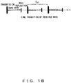
- This is because the pulse Doppler method figures out fd by sampling a Doppler shift frequency fd at a repetitive frequency fprf as shown by
Fig. 1B and1C , and accordingly, it is necessary that:
[Expression 3]
[Expression 4]
- Furthermore, when the velocity of a fluid under measurement is Vf, the Doppler shift frequency fd is expressed by:
[Expression 5]
- A combination of the expressions (3) through (5) results in the expression (2), making it apparent that there is an upper limit to the measurable flow velocity.
- Another problem with regard to the pulse Doppler method is the fact that it is not possible to detect the flow velocity close to the pipe wall on the detector side. That is, a flow rate measurement by the pulse Doppler method is capable of measuring a flow velocity profile if at least a detector with an integrated transmitter/receiver is used, but the velocity measurement accuracy is degraded close to the pipe wall on the detector side. As a countermeasure to the problem, a
patent document 2 has disclosed a method for acquiring a flow rate of a fluid by extrapolating the normally detected flow velocity of a pipe wall part on the opposite side to the pipe wall part equipped with the detector. And a patent document 3 has disclosed a method for making two divided distributions, by dividing a measured velocity distribution into two at the center of the flowing fluid section and acquiring a flow velocity of the entire flowing fluid section by folding one of the divided distributions with a smaller fluctuation. - Both these methods, however, assume the flow of a fluid to be a convex and symmetrical flow and result in degraded flow rate measurement accuracy for asymmetrical flows such as a flow at a bend or at a merge. Also assumed is that the flow only has an axial component, thus degraded flow rate measurement accuracy results if a radial component occurs in a flow at a bend or at a merge.
- On the other hand, the transit time method is a method which employs a pair of detectors integrated with transmitter/receiver as shown by
Fig. 2A , and compares an ultrasonic transmission time T1 (refer toFig. 2B ) from the upstream to downstream side with an ultrasonic transmission time T2 (refer toFig. 2C ) from the downstream to upstream side and acquires the average flow velocity V and flow rate Q according to the expressions (6) and (7).
[Expression 6] :
[Expression 7] :
- While the method has problems, such as a low accuracy, a slow response and a vulnerability to bubbles or impurities, as compared to the above described pulse Doppler method, it has advantages such as the capability of measurement of a fluid without bubbles or impurities, and an absence of a limitation of a measurable range contrary to the pulse Doppler method.
- As described so far, there are advantages and disadvantages to both the pulse Doppler method and the transit time method, since the conventional method for measuring a flow rate using a single measurement instrument utilized either the pulse Doppler method or the transit time method, is faced with the technical problem of a reduced measurement accuracy or inability of measurement depending on the velocity of a fluid as the subject of measurement or the conditions such as inclusion of bubbles.
- According to
US 2004/0006436 a pair of multi-frequency ultrasound transducer surround a fluid flow and are configured to operate under computer control in both a mono-static and a bi-static mode at each of themultiplefrequencies. In the mono-static mode, pulsed wideband Doppler shift measurements provide the velocity profile across the fluid flow which can be combined with measured pressure drops to determine the rheogram-a plot of shear stress versus shear rate. Velocity profile data from each frequency can be combined to form a composite velocity profile. In the bi-static mode, transmission data is collected that improves the accuracy and robustness of the velocity profile and provides supplemental material property information. The system is configured for automated operation for a wide variety of fluid types and can be reconfigured and/or monitored remotely. - [Patent document 1] laid-open Japanese patent application publication No.
2004-12205 - [Patent document 2] laid-open Japanese patent application publication No.
10-281832 - [Patent document 3] laid-open Japanese patent application publication No.
2004-12204 - A purpose of the present invention is to provide an ultrasonic flowmeter and ultrasonic flow rate measurement method which are capable of improving measurement accuracy and a measurable range without being influenced by the state of a fluid such as a flow velocity and an amount of bubbles.
- Another purpose of the present invention is to accomplish a reduction of production cost and simplification of installing a detector for an ultrasonic flowmeter.
- Yet another purpose of the present invention is to accomplish an improvement of measurement accuracy of a flow rate by eliminating a technical problem inherent to the pulse Doppler method in the case of a single detector while suppressing a cost increase.
- Furthermore, still another purpose of the present invention is to provide a flow rate measurement method and apparatus which are capable of measuring a flow rate with high accuracy across a wide range of velocity by switching between two measurement methods, i.e., the pulse Doppler method and the transit time method, according to a condition, such as a flow velocity profile or an amount of bubbles of a fluid as the subject of measurement.
- According to the present invention there is provided an ultrasonic flowmeter as set out in
claim 1. Further features are set out inclaims 2 and 3 to which attention is hereby directed. - According to the present invention there is provided an ultrasonic flow rate measurement method as set out in claim 4.
- A first aspect of the disclosure is an ultrasonic flowmeter comprising a plurality of flow rate measurement units for measuring a flow rate of a fluid in a pipe by using an ultrasonic wave in mutually different measurement principles.
- A second aspect of the disclosure is an ultrasonic flowmeter comprising: a plurality of flow rate measurement units for measuring a flow rate of a fluid in a pipe by mutually different measurement principles using an ultrasonic wave; and a transducer unit for carrying out an interconversion between an acoustic signal and electric signal by being mounted onto the pipe and being shared among a plurality of the flow rate measurement units.
- A third aspect of the disclosure is an ultrasonic flowmeter comprising: a first flow rate measurement unit for detecting a flow rate of a fluid in a pipe by using a transit time method; a second flow rate measurement unit for detecting a flow rate of a fluid in the pipe by using a pulse Doppler method; a plurality of first and second transducer units, being mounted onto the pipe in which a fluid as the subject of measurement flows through, each of which carries out an interconversion between an acoustic signal and electric signal; and a transducer changeover unit for making the first and second flow rate measurement units share the transducer unit.
- A fourth aspect of the disclosure is an ultrasonic flow rate measurement method for measuring a flow rate of a fluid within a pipe by using an ultrasonic wave, measuring a flow rate by a plurality of flow rate measurement units, which use respectively different measurement principles, sharing a plurality of transducer units, each of which, being mounted onto the pipe, carries out an interconversion between an acoustic signal and an electric signal, and changing over a connection of the transducer unit for each of the flow rate measurement units.
- A plurality of said flow rate measurement units for example may be configured to include a first flow rate measurement unit for detecting a flow rate of a fluid within said pipe by using a transit time method and a second flow rate measurement unit for detecting a flow rate of the fluid within the pipe by using a pulse Doppler method.
- And a detector changeover unit maybe equipped which allows an operation by at least one detector, so as to enable the pulse Doppler method to use at least one of a pair of detectors for use in the transit time method which requires two detectors.
- A configuration may be such that a pair of detectors can be placed on the mutually opposite sides across the axis of a pipe and at mutually displaced positions in the direction of the flow of a fluid, or may also be such that a pair of detectors can be placed on the same side of a pipe and at mutually separated positions in the direction of the flow of a fluid.
- As described above, the ultrasonic flowmeter according to the disclosure comprises the first flow rate measurement unit and the second flow rate measurement unit with different measurement principles for using them either mutually independently or both simultaneously, thereby making it possible to measure a flow rate of a fluid over a wide range and with high accuracy without an influence of various states of the fluid as the subject of measurement such as a velocity and bubbles by mutually complementing a shortcoming of the other method.
- And sharing a detector by a plurality of measurement methods makes it possible to reduce the number of detectors, and the production and installation costs thereof, thus enabling a measurement of a flow rate of a fluid over a wide range and with a high accuracy, at a low cost.
- And a common use of a pair of detectors for a measurement by the pulse Doppler method and a combination with a measurement result using the both detectors makes it possible to improve the measurement accuracy of a flow rate by preventing a degraded measurement accuracy close to the pipe wall on the installed side, in the case of using a single detector while suppressing a cost increase.
- Furthermore, a fifth aspect of the disclosure is an ultrasonic flowmeter capable of measuring a flow rate by the pulse Doppler method and the transit time method simultaneously in parallel. The present flowmeter comprises at least one pair of electric/ultrasonic transducers necessary for measuring a flow rate by a transit time method; a hardware unit (e.g., consisting of a transmission & receiving time control unit and pulse generator) for providing at least one pair of electric/ultrasonic transducers with a pulse signal necessary for measuring a flow rate by the pulse Doppler method and necessary for measuring a flow rate by the transit time method; a detection circuit for detecting a Doppler frequency shift from a received signal obtained from a discretionary transducer including the one pair of electric/ultrasonic transducers; a conversion circuit for amplifying and analog/digital-converting a first received signal obtained by an ultrasonic pulse transmission from the upstream to the downstream, and a second received signal obtained by an ultrasonic pulse transmission from the downstream to the upstream, both by the one pair of electric and ultrasonic transducers; and a control unit for calculating a flow rate from the detected Doppler frequency shift by the pulse Doppler method and also a flow rate from the output of the conversion circuit by the transit time method.
- A later described fourth embodiment is configured to further comprise a second electric/ultrasonic transducer used only for measuring a flow rate by a pulse Doppler method, wherein the hardware unit provides both the one pair of electric/ultrasonic transducers and the second electric/ultrasonic transducer with a transmission pulse signal, and the detection circuit detects the Doppler frequency shift from a received signal obtained from the second electric/ultrasonic transducer.
- A later described fifth embodiment is configured such that the at least one pair of electric/ultrasonic transducers is one pair only, and the ultrasonic flow rate meter further comprises a switch unit, being inserted between an input of a pulse signal output and the conversion unit of the hardware unit for a Doppler method and one transducer of the one pair only electric/ultrasonic transducers, for connecting a circuit only for a measuring period by the pulse Doppler method, wherein the detection circuit detects the Doppler frequency shift from a received signal which is an echo of an ultrasonic pulse output from the one transducer.
- The configuration may be such that the control unit and hardware unit collaborate in changing flow rate measurement modes, i.e., a pulse Doppler method, a transit time method and a simultaneous use of both methods, according to an external command or signal.
- Moreover, a fifth aspect of the disclosure is an ultrasonic flowmeter capable of carrying out a flow rate measurement by changing over between a pulse Doppler method and a transit time method. The present ultrasonic flowmeter comprises at least one pair of electric/ultrasonic transducers necessary for measuring a flow rate by a transit time method; a pulse generation unit, comprising a single output terminal, for providing the one pair of electric/ultrasonic transducers with a pulse signal, from the aforementioned terminal, necessary for measuring a flow rate by the transit time method, and to generate and output a pulse signal to one of the one pair of electric/ultrasonic transducers, necessary for measuring a flow rate by the pulse Doppler method; a detection circuit for detecting a Doppler frequency shift necessary for calculating a flow rate by the pulse Doppler method by using one discretionary transducer including the one pair of electric/ultrasonic transducers; a changeover unit (i.e., the transmission & receiving timing control unit) for enabling an amplification and analog/digital conversion of a first received signal obtained by an ultrasonic pulse transmission from the upstream to the downstream and of a second received signal obtained by an ultrasonic pulse transmission from the downstream to the upstream by the above mentioned resources in the present embodiment; and a control unit for calculating a flow rate by the pulse Doppler method from the detected Doppler frequency shift and calculating a flow rate by the transit time method from a result of the analog/digital conversion.
- In a later described sixth embodiment, a detection circuit is configured to comprise an amplifier at a front stage thereof and one pair of analog/digital converters for processing a real part of data and an imaginary part of data respectively at a rear stage, the changeover unit comprises one pair of single-pole dual-throw switch units, being inserted immediately before the one pair of analog/digital converters, for connecting a circuit only for a measurement period of a pulse Doppler method, while connecting an output of the amplifier to one input of the one pair of analog/digital converters, and further comprises a second switch unit whose common terminal is connected to an output terminal of the pulse generation unit and an input terminal of the detection circuit, and one pair of contacts of which is connected to the single pair of electric/ultrasonic transducers, wherein the changeover unit controls change over between the first pair of switch units and the second single-pole dual-throw switch unit for connecting an output of the amplifier to one of the transducers during a measurement period for the pulse Doppler method and changing over to the second switch unit during a measurement period for the transit time method according to a measurement algorithm thereof.
- In a later described seventh embodiment, the configuration is such that the at least one pair of electric/ultrasonic transducers are a plurality of pairs of transducers, a second switch unit is a single-pole switch comprising two times the plural number of contacts which are connected to the plural pairs of transducers one by one, and the changeover unit allocates a measurement period of a pulse Doppler method and that of a transit time method to each pair of the plural pairs of transducers and, for the each pair, changes over the second switch unit so that an input of the amplifier is connected to one of the applicable pair of transducers during a measurement period of the pulse Doppler method, while the amplifier is connected to the applicable pair of transducers for a measurement period of the transit time method according to a measurement algorithm thereof.
- The configuration may be such that the control unit and the changeover unit collaborate in changing flow rate measurement modes, i.e., a pulse Doppler method, a transit time method and a simultaneous use of both methods, according to an external command or signal.
-
-
Fig. 1A is a conceptual diagram describing the principle of a flow rate measurement by a pulse Doppler method by using an ultrasonic wave; -
Fig. 1B is a conceptual diagram describing the principle of a flow rate measurement by a pulse Doppler method by using an ultrasonic wave; -
Fig. 1C is a conceptual diagram describing the principle of a flow rate measurement by a pulse Doppler method by using an ultrasonic wave; -
Fig. 2A is a conceptual diagram describing the principle of a flow rate measurement by a transit time method by using an ultrasonic wave; -
Fig. 2B is a conceptual diagram describing the principle of a flow rate measurement by a transit time method by using an ultrasonic wave; -
Fig. 2C is a conceptual diagram describing the principle of a flow rate measurement by a transit time method by using an ultrasonic wave; -
Fig. 3 is a conceptual diagram exemplifying a comprisal of an ultrasonic flowmeter; -
Fig. 4 is a conceptual diagram exemplifying a comprisal of an ultrasonic flowmeter; -
Fig. 5 is a conceptual diagram exemplifying an operation of the ultrasonic flowmeter shown byFig. 4 ; -
Fig. 6 is a block diagram exemplifying a comprisal of an ultrasonic flowmeter; -
Fig. 7 is a conceptual diagram exemplifying an operation of the ultrasonic flowmeter shown byFig. 6 ; -
Fig. 8 is a conceptual diagram exemplifying an operation of the ultrasonic flowmeter shown byFig. 6 ; -
Fig. 9 is a summary block diagram showing a comprisal of an ultrasonic flowmeter; -
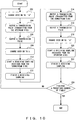
Fig. 10 is a flow chart exemplifying a flow rate measurement operation of the transit time method carried out by atransmission pulse generator 122,transducers signal processing unit 140; -
Fig. 11 is a summary block diagram showing a comprisal of an ultrasonic flowmeter; -
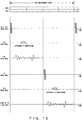
Fig. 12 shows a state of a switch, and signal timings, in the process of measurement operations being carried out by both methods; -
Fig. 13 is a summary block diagram showing a comprisal of an ultrasonic flowmeter; -
Fig. 14 describes states ofswitches SW 1, SW 3 and SW 4 in an operation of an ultrasonic flowmeter; -
Fig. 15A is a summary block diagram showing a comprisal of an ultrasonic flowmeter; -
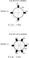
Fig. 15B is a summary cross-sectional diagram exemplifying a placement of transducers for an ultrasonic flowmeter; -
Fig. 15C is a summary cross-sectional diagram exemplifying a placement of transducers for an ultrasonic flowmeter; and -
Fig. 16 describes states of switches SW1a, SW 3 and SW 4 in an operation of anultrasonic flowmeter 104 which is operated on one of the pairs of transducers (e.g., T= 111, 112 or 113). - The following is a detailed description of the preferred embodiments of the disclosure while referring to the accompanying drawings. Note that those components common to respective drawings and embodiments are designated by the same component reference labels and duplicate descriptions are omitted in the following descriptions.
-
Fig. 3 is a conceptual diagram exemplifying a comprisal of an ultrasonic flowmeter for carrying out an ultrasonic flow rate measurement method according to an embodiment of the disclosure. - The ultrasonic flowmeter according to the present embodiment, being mounted onto a
pipe 50 in which a fluid 51 as the subject of measurement flows, comprises a plurality ofdetectors detectors piezoelectric element 40a for carrying out an interconversion between an acoustic signal, such as an ultrasonic oscillation, and electric signal and awedge body 40b, lying between thewedge body 40b and the outer wall surface of thepipe 50, for transmitting an ultrasonic oscillation generated by thepiezoelectric element 40a into thepipe 50 at a predetermined incidence angle to transmit the ultrasonic oscillation of the side of thepipe 50 to thepiezoelectric element 40a, for example as shown byFig. 7 . - The pair of
detectors pipe 50 and in positions displaced toward the upstream and downstream of the flow direction of the fluid 51, with the mutual positions being on the propagation paths of the ultrasonic waves emitted from each other. Such a mounting method for detectors is summarily called a "Z method" for convenience. - And the
detector 43 is installed so that the emitting path of its ultrasonic wave through the center axis of thepipe 50 is in a direction slanting toward the downstream when viewed from the installed position of thedetector 43. - The pair of
detectors detector changeover switch 15, received signalamplification control unit 11, A/D converter 12, propagationtime calculation unit 13, flowrate calculation unit 14 and a transit time method unit 10 (i.e., a first flow rate measurement unit) which is comprised of a transmissionpulse generation unit 31 and transmission & receptiontime control unit 32 by way of adetector changeover switch 15. - The transit time method unit 10: (1) generates an ultrasonic wave oscillation by applying a transmission pulse power, which is output from the transmission
pulse generation unit 31 synchronously with atransmission initiation signal 32a output from the transmission & receptiontime control unit 32, to onedetector 41 by way of thedetector changeover switch 15; which is (2) immediately followed by changing over thedetector changeover switch 15 to thedetector 42 side, receiving an ultrasonic wave arriving thereat, converting it into an electric signal, inputting it to the received signalamplification control unit 11 for amplification, further followed by the A/D converter 12 converting the received signal to digital synchronously with an A/D sampling clock 32b which is output from the transmission & receptiontime control unit 32 and inputting it to the propagationtime calculation unit 13. The aforementioned operations (1) and (2) are carried out alternately by changeover operations of the applicabledetector changeover switch 15 changing over between a transmission and a reception side of thedetectors - And the propagation
time calculation unit 13 detects a flow velocity of the fluid 51 based on the transmission delay time of the ultrasonic wave propagating through thepipe 50 between thedetectors Fig. 2A through 2C , and the flowrate calculation unit 14 carries out the operations of calculating a flow rate from the flow velocity and outputting it by way of a measurement valueoutput changeover switch 34. - And the
detector 43 is connected to a received signalamplification control unit 21, A/D converter 22, flow velocityprofile calculation unit 23,integral calculation unit 24 and pulse Doppler method unit 20 (i.e., a second flow rate measurement unit) comprised of the transmissionpulse generation unit 31 and transmission & receptiontime control unit 32 which are common to the transittime method unit 10. - And the pulse
Doppler method unit 20 emits an ultrasonic wave into thepipe 50 by applying a transmission pulse power, which is output from the transmissionpulse generation unit 31 synchronously with thetransmission initiation signal 32a output from the transmission & receptiontime control unit 32, to thedetector 43, amplifies an echo wave reflected by bubbles, et cetera, within the fluid 51 and received by the received signalamplification control unit 21, and inputs to the flow velocityprofile calculation unit 23 by converting it into a digital signal by the A/D converter 22 synchronously with an A/D sampling clock 32c output from the transmission & receptiontime control unit 32; while the flow velocityprofile calculation unit 23 carries out the operations of calculating a flow velocity profile within thepipe 50 according to the principle exemplified byFig. 1A through 1C , converts it into a flow rate by theintegral calculation unit 24 and outputs it to the measurement valueoutput changeover switch 34. - The comprisal is such that on the output sides of the transit
time method unit 10 and pulseDoppler method unit 20 is equipped the measurement valueoutput changeover switch 34, by way of which the outputs of the transittime method unit 10 and pulseDoppler method unit 20 are selectively output. - The transmission
pulse generation unit 31 and transmission & receptiontime control unit 32, which are equipped commonly to the transittime method unit 10 and pulseDoppler method unit 20, as is the measurement valueoutput changeover switch 34, are controlled so as to determine which of the operations is to be carried out, that is, for the above described transittime method unit 10 or pulseDoppler method unit 20 by anoutput selection signal 33a and measurementmethod selection signal 33b which are output from a measurement methodchangeover control unit 33. - And
measurement state data 13a and themeasurement state data 23a, which are output from the propagationtime calculation unit 13 comprised by the transittime method unit 10 and the flow velocityprofile calculation unit 23 comprised by the pulseDoppler method unit 20, respectively, are input to the measurement methodchangeover control unit 33 which then judges whether the transittime method unit 10, pulseDoppler method unit 20, or both, is to operate based on the data. - As described above, the present embodiment is configured to measure a flow rate of the fluid 51 within the
pipe 50 by changing over between the transittime method unit 10 and pulseDoppler method unit 20 by the measurement methodchangeover control unit 33 controlling the transittime method unit 10 and pulseDoppler method unit 20, and further the measurement valueoutput changeover switch 34, while making judgment of operating conditions of the transittime method unit 10 and pulseDoppler method unit 20 based on information such as themeasurement state data 13a and themeasurement state data 23a. Therefore, it is possible to measure a flow rate over a limitlessly wide range of measurement and with high accuracy by employing the respective advantages of the transittime method unit 10 and pulseDoppler method unit 20. - For instance, if a measurable range is found to be exceeded by the
measurement state data 23a during a measurement by the pulseDoppler method unit 20, or an absence of bubbles or impurities within the fluid 51 has precluded a measurement, then the transittime method unit 10 is initiated and at the same time an output of the measurement valueoutput changeover switch 34 is changed over to the transittime method unit 10, thereby enabling a continuation of the measurement. - As described above, the measurement method
changeover control unit 33 determines a state of the fluid 51 within thepipe 50 from each measurement result based on themeasurement state data 13a and themeasurement state data 23a and changes over to a suitable method among a parallel operation of the transittime method unit 10 and pulseDoppler method unit 20, the former method only or the latter method only by a changeover control to the transmissionpulse generation unit 31 and transmission & receptiontime control unit 32 by theoutput selection signal 33a and a change control of the measurement valueoutput changeover switch 34 by the measurementmethod selection signal 33b, thereby making it possible to accomplish a high measurement accuracy for a wide measurement range without an influence of a state of a fluid. -
Fig. 4 is a conceptual diagram exemplifying a comprisal of an ultrasonic flowmeter according to an embodiment of the present invention. The comprisal shown byFig. 4 exemplifies the case of placing adetector changeover switch 35 at the front stage of the received signalamplification control unit 21 comprised by the pulseDoppler method unit 20 and sharing both of a pair of detector 41 (i.e., a first transducer unit) and detector 42 (i.e., a second transducer unit) with the pulseDoppler method unit 20 in the comprisal shown by the above describedFig. 3 . - That is, the example comprisal shown by
Fig. 4 reduces the number of detectors from three to two from that of theFig. 3 by eliminating thedetector 43 dedicated to the pulseDoppler method unit 20 as a result of sharing either one or both of the pair ofdetectors time method unit 10 by connecting the pair thereof to the pulseDoppler method unit 20 by way of thedetector changeover switch 35. - There are two methods, i.e., the above described "Z method" and a later described "V method", of mounting the detectors for the transit time method in the transit
time method unit 10. - In the "Z method", a pair of the
detectors pipe 50 and displaced toward the upstream and the downstream, with each being positioned on the path of the ultrasonic wave emitted from the other of thedetectors Fig. 4 . - And in the case of mounting by the "Z method", sharing both of the pair of the
detectors detector changeover switch 35 and acquiring a flow velocity profile over the entire diameter of the pipe by combining the parts from the pipe center to the pipe wall on the opposite side (i.e., the far side of the applicable detector) among a flow velocity profile measured by each of thedetectors Fig. 5 , thereby enabling a high accuracy flow rate measurement even for an asymmetrical flow. - That is, for the pulse
Doppler method unit 20 according to the example comprisal shown byFig. 4 , a flow velocity profile calculation part comprises a flow velocity profile calculation unit 23-1 for calculating a flow velocity profile (i.e., the left half ofFig. 5 ) detected by connecting thedetector changeover switch 35 to the side ofdetector 41, a flow velocity profile calculation unit 23-2 for calculating a flow velocity profile (i.e., the right half ofFig. 5 ) detected by connecting thedetector changeover switch 35 to the side ofdetector 42 and an input changeover switch 23-3 for changing over between the flow velocity profile calculation unit 23-1 and flow velocity profile calculation unit 23-2 by aselection signal 32d from the transmission & receptiontime control unit 32 by linking with the changeover operation of thedetector changeover switch 35. - This configuration measures a
flow velocity profile 51a for the half of the cross section on the far side from thedetector 41 by making the flow velocity profile calculation unit 23-1 operate in the state of connecting the pulseDoppler method unit 20 to theapplicable detector 41, while measuring aflow velocity profile 51b for the half of the cross section on the far side from thedetector 42 in the state of being connected to theapplicable detector 42, and theintegral calculation unit 24 at the later stage outputs a flow rate measurement value by calculating a flow rate based on aflow velocity profile 51c of the entire cross sectional area as a result of adding respective flow velocity profiles of the flow velocity profile calculation unit 23-1 (i.e., the detector 41) and flow velocity profile calculation unit 23-2 (i.e., the detector 42), as exemplified byFig. 5 . - As described above, the present embodiment shown by
Figs. 4 and5 makes the pulseDoppler method unit 20 side employing the pulse Doppler method share a pair of thedetectors time method unit 10, by way of thedetector changeover switch 35, thereby compensating for a degraded accuracy of a flow velocity profile measurement close to a detector, which is a technical problem of the pulse Doppler method in the case of using a single detector, by adding the measurement data of thedetectors - It is also possible to make the transit
time method unit 10 measure a flow rate distribution in parallel with a measurement processing of the pulseDoppler method unit 20 by receiving an acoustic signal by connecting the detector 42 (or the detector 41), which is not connected to the pulseDoppler method unit 20, to the transittime method unit 10 during a flow rate measurement by using the detector 41 (or the detector 42) of the aforementioned pulseDoppler method unit 20. -
Fig. 6 is a block diagram exemplifying a comprisal of an ultrasonic flowmeter according to another embodiment of the disclosure; andFigs. 7 and8 are conceptual diagrams describing example operations thereof. - The embodiment shown by
Fig. 6 is configured to place adetector 41 in the downstream of the axial direction on the same side of thepipe 50 and place adetector 42 in the upstream so that the propagation paths of ultrasonic waves emitted from thedetectors pipe 50 at the time of measurement by the transittime method unit 10. Such a placement method for detectors is summarily called a "V method." - And in the embodiment shown by
Fig. 6 , the transittime method unit 10 causes thedetector 41 to send out an ultrasonic wave and measure a flow velocity profile of the fluid 51 in thepipe 50 by detecting an acoustic signal incident on theother detector 42 after the ultrasonic wave is reflected by the wall surface on the other side. - Meanwhile, the pulse
Doppler method unit 20 carries out a measurement operation of a flow velocity profile as described later by using thedetectors detector changeover switch 35. - That is, in the case of measuring a flow velocity by using one detector in the pulse Doppler method, a flow velocity is acquired assuming the flow velocity Vf (in the direction of flow) to be parallel with the axis of the
pipe 50, and as such the Doppler shift frequency is fd ∞ Vf*sinθf, where the incident angle of an ultrasonic wave vis-à-vis the fluid 51 is θf as shown byFig. 7 . - Because of this, if the flow direction (with a flow velocity Vfx) of the fluid 51 is not parallel with the axial direction of the
pipe 50, having an error component Vfh in the direction of the diameter of thepipe 50, then a velocity distribution α of onedetector 41 is expressed by the expression (8), resulting in a measured flow velocity value including an error component, i.e., Vfh*cosθf as shown byFig. 8 .
[Expression 8]
[Expression 9]
- Accordingly, if the
detectors Fig. 6 , both of a pair of thedetectors time method unit 10 and pulseDoppler method unit 20 so as to cancel the component Vfh in the direction of the diameter by taking the difference of flow velocity profiles measured by the respective detectors, thereby making it possible to calculate a velocity distribution in the direction of the axis and measure the flow rate with high accuracy. - That is, a flow velocityprofile α of the expression (8) of one
detector 41 and a flow velocity profile β of the expression (9) of theother detector 42 are respectively calculated by the flow velocity profile calculation unit 23-1 and flow velocity profile calculation unit 23-2 comprised by the pulseDoppler method unit 20 as shown byFig. 8 , and the difference of the two flow velocity profiles is averaged, that is, (α -β)/2, to make it the flow velocity profile, thereby enabling an accurate flow velocity profile and a flow rate measurement based thereon if there is an asymmetrical flow or a radial direction component in the fluid 51 within thepipe 50. - As described above, the embodiment according to the disclosure enables a flow rate measurement by using the pulse
Doppler method unit 20 of the pulse Doppler method and the transittime method unit 10 of the transit time method either in parallel or by changing over depending on the state of the fluid 51 flowing in thepipe 50, hence making it possible to improve a measurement accuracy and measurable range. Also, sharing thedetectors - Also, the pulse
Doppler method unit 20, which needs at least one detector, sharing a relevant detector of the transittime method unit 10 which needs at least one pair of detectors and the pulseDoppler method unit 20 combining a plurality of flow velocity measurement results measured by each detector makes it possible to improve a measurement accuracy of a flow rate by the pulse Doppler method for a fluid flow with an asymmetrical flow or with a component in the radial direction, while suppressing a cost increase. - While the above described each embodiment has considered the case of using the transit time method and pulse Doppler method, each embodiment may be widely applied to ultrasonic flow rate measurement techniques for measuring flow velocity and flow rate by using ultrasonic waves.
-
Fig. 9 is a summary block diagram showing a comprisal of an ultrasonic flowmeter according to a fourth embodiment of the disclosure. Referring toFig. 9 , anultrasonic flowmeter 101 according to the present disclosure is capable of carrying out both flow rate measurement by the pulse Doppler method and the transit time method simultaneously in parallel by comprising both of a measurement system (110 plus 130) for the pulse Doppler method and that (111 plus 140) for the transit time method. - That is, the ultrasonic flowmeter 101 comprises an electric/ultrasonic transducer (simply "transducer" hereinafter) 110 for transmitting and receiving an ultrasonic wave by being mounted onto the outer wall of a pipe, in which flows a fluid as the subject of measurement, in order to measure a flow rate by the pulse Doppler method, one pair of transducers 111u and 111d (simply "111" as a group hereinafter) which are mounted onto the pipe wall of the pipe at corresponding positions on the upstream and downstream sides in order to measure a flow rate by the transit time method, a transmission & reception timing control unit 120 for controlling a timing of a transmission pulse for supplying the above described transducers 110 and 111 and a timing of processing a received signal from the transducer, a transmission pulse generator 122 for generating a transmission pulse for the transducers 110 and 112 according to a transmission initiation signal from the transmission & reception timing control unit 120, a Doppler frequency shift detection unit 130 for detecting a Doppler frequency shift from a received signal of the pulse Doppler method measurement-use transducer 110, a received signal processing unit 140 for processing a received signal from a transit time method measurement-use transducer 111, a switch SW for switching a transmission & reception signal relating to a measurement by the transit time method, and a calculation control unit 150 for calculating a flow rate from data handed over from the received signal processing unit 140 as well as a flow rate from an real data and an imaginary data obtained from the Doppler frequency shift detection unit 130. The
calculation control unit 150 comprises a microcomputer including a CPU (central processing unit; not shown herein) and typically operates under a control of a program stored by a ROM (read only memory apparatus), thereby controlling the entirety of theultrasonic flowmeter 101. While the transmission & receptiontiming control unit 120 can be constituted by individual components, it can easily be accomplished by use of a PAL (programmable array logic), et cetera. - The Doppler frequency
shift detection unit 130 comprises anamplifier 131 for amplifying a signal from thetransducer 110, anorthogonal wave detector 132 whose input is connected to an output of theamplifier 131, a pair offilters 133R and 133I which is connected to an real part data output and an imaginary part data output, respectively, and a pair of analog/digital (A/D)converters 134R and 134I which is connected to thefilters 133R and 133I, respectively. Meanwhile, the receivedsignal processing unit 140 comprises anamplifier 131P, which is the same as theamplifier 131, and anA/D converter 134P. - Let an operation of the
ultrasonic flowmeter 101 according to the present embodiment of the disclosure be described briefly. First, thecalculation control unit 150 sends a flow rate measurement start instruction MS to the transmission & receptiontiming control unit 120. In response to this, the transmission & receptiontiming control unit 120 provides thetransmission pulse generator 122 an instruction to transmit a pulse Doppler method measurement-use transmission pulse TD and a transit time method measurement-use first transmission pulse (i.e., a transmission pulse for providing to theupstream transducer 111u for example) TP1, and thetransmission pulse generator 122 transmits and outputs a transmission pulses TD and TP1 immediately. This initiates a flow rate measurement by the pulse Doppler method and by the transit time method simultaneously. - A flow rate calculation processing of the pulse Doppler method carried out by the Doppler frequency
shift detection unit 130 andcalculation control unit 150 may be carried out by any flow rate calculation method, including the conventional method and a flow rate calculation method which might be formulated in the future. Likewise, a flow rate calculation processing of the transit time method carried out by the receivedsignal processing unit 140 andcalculation control unit 150 maybe carried out by any flow rate calculation method, including the conventional method and a flow rate calculation method which might be formulated in the future. - First, in a flow rate measurement by the pulse Doppler method, as a transmission pulse TD is applied to the
transducer 110, an ultrasonic signal is emitted into the pipe from thetransducer 110, an echo of the ultrasonic signal is converted into an electric signal by thetransducer 110 and the electric signal is received therefrom as a received signal RD. The received signal RD is input to the Doppler frequencyshift detection unit 130 for detecting a Doppler frequency shift. Thecalculation control unit 150 calculates a flow velocity profile and a flow rate based on the received data from the Doppler frequencyshift detection unit 130. -
Fig. 10 is a flow chart exemplifying a flow rate measurement operation of the transit time method carried out by thetransmission pulse generator 122, thetransducers signal processing unit 140. InFig. 10 , a common terminal of the switch SW is connected to the contact "a" (step 202) to let thetransmission pulse generator 122 transmit the first transmission pulse TP 1 (step 204). This causes theupstream side transducer 111u to output an ultrasonic pulse toward thedownstream side transducer 111d (step 206). The next step is to connect the common terminal of the switch SW to the contact b (step 208), and to let the receivedsignal processing unit 140 sample and A/D-convert a received signal RP1 from thetransducer 111d in a predetermined interval to hand the result over to the calculation control unit 150 (step 210). Upon finishing the A/D conversion (step 212), let thetransmission pulse generator 122 transmit the second transmission signal TP2 (step 214) which causes thedownstream transducer 111d to output an ultrasonic pulse toward the upstream transducer 111u (step 216). The next step is to connect the common terminal of the switch SW to the contact "a" (step 218) to cause the receivedsignal processing unit 140 to sample and A/D-convert a received signal RP2 from thetransducer 111u in a predetermined interval to hand the result over to the calculation control unit 150 (step 220). Upon finishing the A/D conversion (step 222), judge whether or not the above described processing has been carried out a predefined number of times and repeat the processing until the predefined number of times is reached (step 224) . Thecalculation control unit 150 calculates a flow velocity and flow rate based on the received data from the receivedsignal processing unit 140. - As described above, the
ultrasonic flowmeter 101 shown byFig. 9 is fully furnished with the measurement system of the pulse Doppler method (110 plus 130) and that of the transit time method (111 plus 140) so as to be capable of carrying out flow measurements by the pulse Doppler method and transit time method simultaneously in parallel. -
Fig. 11 is a summary block diagram showing a comprisal of an ultrasonic flowmeter according to an embodiment of the present invention. Referring toFig. 11 , theultrasonic flowmeter 102 according to the present embodiment is the same as theultrasonic flowmeter 101 shown byFig. 9 with the exceptions that a switch SW1 is added, the switch SW is replaced by a switch SW2 and the transmission & receptiontiming control unit 120 is replaced by a transmission & receptiontiming control unit 120a, all in place of the pulse Doppler method measurement-use transducer 110 which is eliminated. Accordingly, the description here only deals with the differing portions. To begin with, the contacts a and b of the switch SW2, which replaces the switch SW, are additionally connected to the contacts a and b of the switch SW1, respectively. The common terminal of the switch SW1 is connected to the output terminal of a transmission signal TD of thetransmission pulse generator 122 and an input terminal of the Doppler frequencyshift detection unit 130. The "a" contacts of the switches SW1 and SW2 are connected to theupstream side transducer 111u and the b contacts of the switches SW1 and SW2 are connected to thedownstream side transducer 111d. - The
ultrasonic flowmeter 102 according to the present embodiment is furnished with both the Doppler frequencyshift detection unit 130 and receivedsignal processing unit 140 and accordingly requires a signal changeover by the switch SW1 to use the pair oftransducers - The next description is of an operation of the
ultrasonic flowmeter 102 according to the fifth embodiment of the present invention. First, thecalculation control unit 150 transmits a flow rate measurement start instruction MS to the transmission & receptiontiming control unit 120a. In response to this, the transmission & receptiontiming control unit 120a provides thetransmission pulse generator 122 an instruction for transmitting a transmission signal TD (also a TP1) for a common use between the pulse Doppler method and transit time method so that thetransmission pulse generator 122 transmits and outputs a transmission pulse TD (also a TP1) promptly. This initiates flow rate measurements by the pulse Doppler method and transit time method simultaneously. -
Fig. 12 shows a state of a switch, and various signal timings, in the process of measurement operations being carried out by both the pulse Doppler method and transit time method simultaneously in parallel according to the fifth embodiments of the present invention. Referring toFig. 12 , the transmission & receptiontiming control unit 120a connects the common terminal of the switch SW1 to the contact "a" as the initial setup (simply stated as "change the switch SW1 over to 'a' " hereinafter) and also changes the switch SW2 over to "b". As described above, when thetransmission pulse generator 122 outputs a transmission signal TD (also a TP1) which is then supplied to theupstream transducer 111u from the contact "a" of the switch SW1. A part of an ultrasonic pulse which is output from thetransducer 111u is reflected to return thereto while the other part is sensed by thedownstream transducer 111d. - The received signal RP1 sensed and converted by the
downstream transducer 111d is supplied from the switch SW2 to an input terminal of the receivedsignal processing unit 140 by way of the contact SW2b for use in a flow rate measurement by the transit time method. - In the meantime, the ultrasonic pulse returning to the
transducer 111u is converted into an electric signal to become the received signal RD which is then supplied from the switch SW1 to an input terminal of the Doppler frequencyshift detection unit 130 by way of the contact "a" of the switch SW1 for use in a flow rate calculation of the pulse Doppler method. - Then, the transmission & reception
timing control unit 120a change the switch SW1 over to "b" and the switch SW2 over to "a"; and then causes thetransmission pulse generator 122 to generate a pulse Doppler method measurement-use transmission signal TD (which also has a role as the second transmission signal TP2 for use in a flow rate measurement by the transit time method) . The transmission signal TD (also the TP2) is supplied to thedownstream transducer 111d by way of the contact b of the switch SW1. The transmission signal TD is output from thetransducer 111d as an ultrasonic pulse which is then converted into an electric signal by theupstream transducer 111u to become a received signal RP2. The received signal RP2 is supplied from the switch SW2 to an input terminal of the receivedsignal processing unit 140 by way of the contact "a" of the switch SW2, and is used for a flow rate calculation of the transit time method together with the above described received signal RP1. And the ultrasonic pulse output from thetransducer 111d is scattered by bubbles, etcetera, within the fluid, with a part of the scattered ultrasonic wave returning to thetransducer 111d as an echo which is then supplied to the Doppler frequencyshift detection unit 130 by way of the contact "b" of the switch SW1 as an echo signal of the transmission pulse TD. - A repetition of the above described measurement cycles for a predefined number of times carries out flow rate measurements by the pulse Doppler method and transit time method simultaneously in parallel.
- Note that though in the above description measurement by the pulse Doppler method is repeated two times in one measurement cycle, one measurement alone may, however, be adequate.
- Also, the above described simultaneous parallel two-method operation does not use a transit time method-use pulse output of the
transmission pulse generator 122. Accordingly, thetransmission pulse generator 122 can only have a function of generating a single kind of pulse while carrying out the both methods simultaneously in parallel. The ultrasonic flowmeter shown byFig. 11 , however, has an output terminal for the pulse Doppler method and one for the transit time method in thetransmission pulse generator 122 by assuming the case of making the both methods operate by changing over therebetween by using differently specified transmission pulses. -
Fig. 13 is a summary block diagram showing a comprisal of an ultrasonic flowmeter according to an embodiment of the present invention. Referring toFig. 13 , theultrasonic flowmeter 103 according to the present embodiment is the same as theultrasonic flowmeter 102 shown byFig. 11 , with the exception of the removal of the switch SW2 and receivedsignal processing unit 140, the replacement of the transmission & receptiontiming control unit 120a by the 120 b, the replacement of thetransmission pulse generator 122 by the 122a and the replacement of the Doppler frequencyshift detection unit 130 by the 130a. Therefore, the description here only pertains to the differences. The Doppler frequencyshift detection unit 130a is the same as the Doppler frequencyshift detection unit 130 except for the insertion of a switch SW3 between thefilter 133R and the A/D converter 134R and the insertion of a switch SW4 between the filter 133I and the A/D converter 134I. - That is, the present embodiment uses the amplifier and A/D converter comprised by the Doppler frequency shift detection unit both for the pulse Doppler method and transit time method. Therefore, a flow rate measurement is enabled by using the both methods alternately or by selecting either method by an instruction from an upper echelon system such as a microcomputer, while a measurement signal processing of the both methods cannot be carried out simultaneously in parallel.
- Note that the present embodiment carries out a flow rate measurement by the pulse Doppler method and by the transit time method alternately, and therefore the
transmission pulse generator 122a has only one transmission signal output terminal, and generates and outputs a transmission signal Tm (where m equals D, P1 or P2). -
Fig. 14 describes states of switches SW1, SW3 and SW4 in an operation of theultrasonic flowmeter 103 according to the present embodiment of the present invention. First, in the case of measurement by the pulse Doppler method all the switches SW1, SW3 and SW4 are changed over to "a". As such a circuit comprised of thetransducer 111u, switch SW1 and Doppler frequencyshift detection unit 130a becomes the same as the circuit made up of thetransducer 110 and Doppler frequencyshift detection unit 130, thus enabling a measurement by the pulse Doppler method. Incidentally, changing the switches SW3 and SW4 over to "a" and the switch SW1 over to "b" enables a measurement by the pulse Doppler method by using thedownstream transducer 111d, which is apparent to the business entity of the present invention. - On the other hand, the case of measurement by the transit time method only requires a change of both of the switches SW3 and SW4 over to "b". This makes it clear that a circuit composed of the switch SW1,
amplifier 131, switch SW4 and A/D converter 134I becomes the same as the circuit made up of the switch SW1,amplifier 131P and A/D converter 134P shown byFig. 9 , thus enabling a measurement by the transit time method. During a measurement by the transit time method, exactly the same changeover control is carried out for the switch SW1 as the switch SW shown byFig. 10 . Note that although the functionality of the switch SW3 is not necessary, the present embodiment shows the switch SW3 because it is desirable to make signal paths of the sine and cosine components between the orthogonal wave detection and AD conversion equal. -
Fig. 15A is a summary block diagram showing a comprisal of an ultrasonic flowmeter according to an embodiment of the present invention. Referring toFig. 15A , anultrasonic flowmeter 104 according to the present embodiment is the same as theultrasonic flowmeter 103 shown byFig. 13 , except for the replacement of the transmission & receptiontiming control unit 120b by 120c and the switch SW1 by a six-contact single-pole switch SW1a, and the addition of the pairs oftransducers Fig. 15B and 15C , the pairs oftransducers downstream transducers - The
ultrasonic flowmeter 104 according to the present embodiment measures by the pulse Doppler method and transit time method for each of the pairs oftransducers -
Fig. 16 describes states of switches SW1a, SW3 and SW4 in an operation of theultrasonic flowmeter 104 which is operated using one of the pairs of transducers T (e.g., T= 111, 112 or 113) according to the present embodiment. In the case of measurement by the pulse Doppler method, both of the switches SW3 and SW4 are changed over to "a", and the switch SW1-T is changed over to SW1-Tu. By so doing, a circuit comprised of the upstream transducer Tu, switch SW1a and Doppler frequencyshift detection unit 130a becomes the same as the circuit comprised of thetransducer 110 and Doppler frequencyshift detection unit 130 shown byFig. 9 , thus a measurement by the pulse Doppler method is enabled. It is of course apparent to the business entity of the present invention that a measurement by the pulse Doppler method is enabled by using the downstream transducer by changing the switch SW1-T over to SW1-Td. - And, a measurement by the transit time method only requires changing the both switches SW3 and SW4 over to "b". By so doing, a circuit made up of the switch SW1-T,
amplifier 131, switch SW4 and A/D converter 134I becomes the same as the circuit made up of thetransducer 110 and Doppler frequencyshift detection unit 130 shown byFig. 9 demonstrating that a measurement by the transit time method is enabled. During a measurement by the transit time method, the same changeover control is carried out for the switch SW1-T as for the switch SW as shown byFig. 10 (where the u and d for identifying contacts correspond to a and b respectively). - While the present embodiment describes the example of using three pairs of transducers, it is, however, possible to accomplish a similar result with two, four, or more pairs thereof by equalizing the number of transducers with that of the contacts of the switch SW1a.
- It is easy for the business entity to change, modify or add to the above described embodiments in accordance with the technical concept or principle of the present invention as set out in the claims.
- For instance, while the second embodiment is configured to measure by the pulse Doppler method an echo signal of the first transmission pulse of each measurement cycle by using the
transducer 111u, it is also possible to measure by the pulse Doppler method an echo signal of the second transmission pulse by using thetransducer 111d. - Meanwhile, the third and fourth embodiments have shown examples of changing over between the pulse Doppler method and transit time method, a changeover method, however, can conceivably be different. For instance, the configuration may be such that the
calculation control unit 150a is disposed for receiving a method changeover command or signal externally (e.g., of a user or an upper echelon system). In response to the method changeover command or signal, thecalculation control unit 150 may let the transmission & receptiontiming control unit 120b change over methods. - And while the fourth and fifth embodiments describe the example of carrying out the pulse Doppler method and transit time method simultaneously in parallel, the configuration may also be such that the
calculation control unit 150 is disposed for receiving a method changeover command or signal externally (e.g., of a user or an upper echelon system) and thecalculation control unit 150a receiving the signal lets the transmission & reception timing control unit change over flow rate measurement modes between the pulse Doppler method, transit time method and both methods simultaneously according to the method changeover command or signal. - The present invention makes it possible to measure a flow rate of a fluid over a wide range and with a high accuracy without an influence by a state of the fluid such as the velocity and amount of bubbles.
- Also the present invention makes it possible to accomplish a reduction of production cost and simplification of installation of a detector for an ultrasonic flowmeter capable of improving a measurement accuracy and measurable range without being influenced by a state of the fluid, such as the velocity and quantity of bubbles.
- Also the present invention makes it possible to accomplish an improvement of flow rate measurement accuracy by eliminating a technical problem specific to the pulse Doppler method in the case of using a single detector while suppressing a cost increase.
- Further the present invention comprises resources necessary for flow rate measurements by both the pulse Doppler method and transit time method, thereby enabling flow rate measurements by the both methods and a flow rate measurement with a high accuracy and over wide range of flow velocities.
Claims (4)
- An ultrasonic flowmeter comprising:a first flow rate measurement unit (10; 140; 130a) for detecting a flow rate of a fluid in a pipe by using a transit time method;a second flow rate measurement unit (20; 130; 130a) for detecting a flow rate of a fluid in the pipe by using a pulse Doppler method;a plurality of first (41; 111u; 112u, 113u) and second (42; 111d; 112d, 113d) transducer units, being mounted onto the pipe in which a fluid as the subject of measurement flows through, each of which carries out an interconversion between an acoustic signal and electric signal; anda transducer changeover unit (33; 120a; 120b; 120c) for making the first and second flow rate measurement units share the transducer unit, whereinsaid plurality of said first and second transducer units are mounted onto said pipe with the first and second transducer units mutually on the opposite sides across the axis of the pipe and at mutually displaced positions in the flow direction of said fluid,
characterized in thatsaid first flow rate measurement unit is adapted to measure a flow rate of the fluid by measuring the time difference between a propagation time of an acoustic signal which is transmitted from the first transducer unit and received by the second transducer unit, and a propagation time of an acoustic signal which is transmitted from the second transducer and received by the first transducer, andsaid second flow rate measurement unit is adapted to acquire a flow velocity profile (51c) of the entire diameter of the pipe by combining the measurement values of flow velocity profiles (51a, 51b) from the center to the pipe wall on the far side as seen from the aforementioned respective transducers from among the flow velocity profile measured by using each of the first and second transducers. - The ultrasonic flowmeter according to claim 1, wherein
said first flow rate measurement unit (10; 140; 130a) includes
a pair of transducer units (41, 42; 111u, 111d; 112u, 112d, 113u, 113d), being mounted onto said pipe, for carrying out an interconversion between an acoustic signal and an electric signal,
a transmission pulse generation unit (31; 122; 122a) for applying a transmission pulse to the transducer units for an ultrasonic transmission,
a receiving signal amplifier control unit (11, 21; 131, 131P; 131) for inputting an ultrasonic receiving signal received at the transducer units,
an analog/digital (A/D) conversion unit (12, 22; 134R, 134I, 134P; 134R, 134I) for converting the receiving signal to a digital signal,
a propagation time operation unit (13) for operating a propagation time difference from a propagation time measured by switching a transmission side and reception side of a pair of the transducer units alternatively,
a flow rate calculation unit (14; 150; 150a) for calculating a flow rate based on the propagation time difference, and
a transmission & reception timing control unit (32; 120a; 120b; 120c), being equipped commonly to said second flow rate measurement unit, for controlling the transmission pulse generation unit and the A/D conversion unit. - The ultrasonic flowmeter according to claim 1, wherein
said second flow rate measurement unit (20; 130; 130a) includes
a transducer unit, being mounted onto said pipe, for carrying out an interconversion between an acoustic signal and an electric signal,
a transmission pulse generation unit (31; 122; 122a) for applying a transmission pulse to the transducer units for an ultrasonic transmission,
a receiving signal amplification control unit 11, 21; 131, 131P; 131) for inputting an acoustic signal received at the transducer unit,
an analog/digital (A/D) conversion unit (12, 22; 134R, 134I, 134P; 134R, 134I) for converting the received signal to a digital signal,
a flowvelocityprofile operation unit (23-1, 23-2; 150; 150a) for measuring a flow velocity profile of said fluid within the cross section of the pipe based on a Doppler shift frequency of an ultrasonic wave which is transmitted and received between the transducer unit and the fluid,
an integral operation unit (24; 150; 150a) for determining a flow rate by integrating the flow velocity profile, and
a transmission & reception timing control unit (32; 120a; 120b; 120c), being equipped commonly with said first flow rate measurement unit, for controlling the transmission pulse generation unit and the A/D conversion unit. - An ultrasonic flow rate measurement method for measuring a flow rate of a fluid within a pipe by using an ultrasonic wave, which method comprises the steps of:measuring a flow rate by a plurality of flow rate measurement units, which uses mutually different measurement principles, sharing a plurality of first (41; 111u; 112u, 113u) and second (42; 111d; 112d, 113d) transducer units, each of which, being mounted onto the pipe, carries out an interconversion between an acoustic signal and an electric signal, and changing over a connection of the transducer unit for each of the flow rate measurement units;wherein said plurality of said flow rate measurement units includes a first flow rate measurement unit (10; 140; 130a) for detecting a flow rate of a fluid within said pipe by using a transit time method and a second flow rate measurement unit (20; 130; 130a) for detecting a flow rate of the fluid within the pipe by using a pulse Doppler method; and the method further comprises the steps of:mounting said first and second transducer units on the mutually opposite sides across the axis of the pipe and at mutually displaced positions in the flow direction of the fluid,
characterized in thatthe first flow rate measurement unit measuring a flow rate of the fluid by measuring a time difference of a propagation time of an acoustic signal transmitted by the first transducer unit and received by the second transducer unit from that of an acoustic signal transmitted by the second transducer unit and received by the first transducer unit, andthe second flow rate measurement unit calculating a flow velocity profile (51c) for the entire diameter of the pipe by combining measurement values from the center of the pipe to the pipe wall on the opposite side viewed from the first and second transducer units respectively, of flow velocity profiles (51a, 51b) which are measured by the aforementioned transducer units respectively.
Applications Claiming Priority (3)
| Application Number | Priority Date | Filing Date | Title |
|---|---|---|---|
| JP2004052348 | 2004-02-26 | ||
| JP2004055250 | 2004-02-27 | ||
| PCT/JP2005/003006 WO2005083370A1 (en) | 2004-02-26 | 2005-02-24 | Ultrasonic flowmeter and ultrasonic flow rate measurement method |
Publications (3)
| Publication Number | Publication Date |
|---|---|
| EP1719980A1 EP1719980A1 (en) | 2006-11-08 |
| EP1719980A4 EP1719980A4 (en) | 2008-03-05 |
| EP1719980B1 true EP1719980B1 (en) | 2017-05-03 |
Family
ID=34914446
Family Applications (1)
| Application Number | Title | Priority Date | Filing Date |
|---|---|---|---|
| EP05719456.5A Active EP1719980B1 (en) | 2004-02-26 | 2005-02-24 | Ultrasonic flowmeter and ultrasonic flow rate measurement method |
Country Status (5)
| Country | Link |
|---|---|
| US (1) | US7437948B2 (en) |
| EP (1) | EP1719980B1 (en) |
| JP (1) | JP4544247B2 (en) |
| CA (1) | CA2557432C (en) |
| WO (1) | WO2005083370A1 (en) |
Families Citing this family (35)
| Publication number | Priority date | Publication date | Assignee | Title |
|---|---|---|---|---|
| JP2006078362A (en) | 2004-09-10 | 2006-03-23 | Kaijo Sonic Corp | Coaxial-type doppler ultrasonic current meter |
| US7523676B2 (en) * | 2006-12-07 | 2009-04-28 | General Electric Company | Ultrasonic flow rate measurement method and system |
| US8019559B1 (en) * | 2007-05-30 | 2011-09-13 | Racine Federated, Inc. | Sonic flow meter and method |
| DE102007029957A1 (en) * | 2007-06-28 | 2009-01-02 | Robert Bosch Gmbh | Ultrasonic sensor with reciprocal transmitting and receiving circuit |
| WO2010015234A2 (en) | 2008-08-04 | 2010-02-11 | Hydro Vision Gmbh | Method and device for determining a flow rate of a fluid |
| JP5321106B2 (en) * | 2009-02-06 | 2013-10-23 | 横河電機株式会社 | Ultrasonic measuring instrument |
| WO2010111355A1 (en) * | 2009-03-24 | 2010-09-30 | Norcross Corporation | In-line viscometer with no moving parts and methods and computer-readable media for maintaining a desired viscosity |
| WO2011040037A1 (en) * | 2009-10-01 | 2011-04-07 | パナソニック株式会社 | Ultrasonic flow rate measuring unit |
| EP2345876B1 (en) * | 2010-01-18 | 2019-09-11 | Flow-Tronic S.A. | Method for avoiding jumps in measurement results and improving accuracy in hybrid flow meters |
| CN101936756B (en) * | 2010-08-31 | 2012-12-19 | 华南理工大学 | Multifrequency phased array ultrasonic Doppler flow detection system and method |
| IL208815A0 (en) | 2010-10-19 | 2011-01-31 | Raphael Valves Ind 1975 Ltd | An integrated ultrasonic flowmeter and hydraulic valve |
| JP2014081281A (en) * | 2012-10-16 | 2014-05-08 | Horiba Ltd | Ultrasonic flow meter |
| CN104864923A (en) * | 2014-02-24 | 2015-08-26 | 通用电气公司 | Circuit assemblies for transmitting and receiving ultrasonic signals as well as system and method adopting circuit assemblies |
| JP2015215171A (en) * | 2014-05-07 | 2015-12-03 | アズビル株式会社 | Ultrasonic flow meter and abnormality determination method for ultrasonic absorber |
| JP2015232519A (en) * | 2014-06-10 | 2015-12-24 | アズビル株式会社 | Clamp-on type ultrasonic flow meter and flow measurement method |
| SG11201609000YA (en) * | 2014-07-29 | 2016-11-29 | Hydrovision Asia Pte Ltd | Improved signal travel time flow meter |
| CN105737916B (en) | 2014-12-08 | 2019-06-18 | 通用电气公司 | Ultrasonic fluid measuring system and method |
| CN104601131B (en) * | 2014-12-23 | 2017-02-22 | 重庆川仪自动化股份有限公司 | Receipt signal strength automatic gain control method for gas ultrasonic flow meter transducer |
| JP6454219B2 (en) * | 2015-05-14 | 2019-01-16 | 株式会社キーエンス | Ultrasonic flow switch |
| CN106404084B (en) * | 2015-08-10 | 2019-02-05 | 杭州思筑智能设备有限公司 | A method of measurement gas flow |
| DE102016006244A1 (en) * | 2016-01-14 | 2017-07-20 | Diehl Metering Gmbh | Ultrasonic fluid meter and method for flow and / or volume determination of a flowing medium |
| CN107218980A (en) * | 2016-03-21 | 2017-09-29 | 深圳市兴源智能仪表股份有限公司 | Full digital device for measuring ultrasonic wave flow |
| JP6751609B2 (en) * | 2016-07-05 | 2020-09-09 | サーパス工業株式会社 | Flow control device |
| DE102016011256A1 (en) | 2016-09-17 | 2018-03-22 | Diehl Metering Gmbh | Method for determining the flow of a flowing medium |
| CN108007509B (en) * | 2016-10-27 | 2020-01-07 | 龙芯中科技术有限公司 | Fluid flow measurement system |
| US10495499B2 (en) | 2017-10-27 | 2019-12-03 | METER Group, Inc. USA | Sonic anemometer |
| EP3517184A1 (en) | 2018-01-24 | 2019-07-31 | Marioff Corporation OY | Fire sprinkler system |
| EP3521773B1 (en) * | 2018-02-06 | 2021-09-29 | SICK Engineering GmbH | Ultrasound flow meter and method of determining a flow speed |
| US11454642B2 (en) * | 2018-08-11 | 2022-09-27 | Yanqin Li | Method and system of acoustic wave measurement of axial velocity distribution and flow rate |
| US10739174B2 (en) * | 2018-08-11 | 2020-08-11 | Yanqin Li | Method and system of acoustic wave measurement of axial velocity distribution and flow rate |
| JP7383256B2 (en) * | 2019-09-18 | 2023-11-20 | 善胤 田村 | Fluid behavior measurement method using reticular ultrasound |
| CN110567543A (en) * | 2019-10-28 | 2019-12-13 | 北京奥特美克科技股份有限公司 | channel flow measuring equipment |
| CN111398626A (en) * | 2019-12-31 | 2020-07-10 | 江苏启泰物联网科技有限公司 | Liquid flow rate monitoring method for railway |
| CN114814285B (en) * | 2022-06-23 | 2022-09-09 | 沈阳佳德联益能源科技股份有限公司 | Ultrasonic flow measurement method |
| TWI846492B (en) * | 2023-05-30 | 2024-06-21 | 桓達科技股份有限公司 | Hybrid ultrasonic flowmeter and its measurement method |
Family Cites Families (25)
| Publication number | Priority date | Publication date | Assignee | Title |
|---|---|---|---|---|
| US4162630A (en) * | 1976-09-20 | 1979-07-31 | University Of Utah | Measurement and reconstruction of three-dimensional fluid flow |
| US4271708A (en) * | 1978-05-16 | 1981-06-09 | Fuji Electric Co., Ltd. | Ultrasonic measuring apparatus |
| JPS5527938A (en) * | 1978-08-21 | 1980-02-28 | Toshiba Corp | Ultrasonic wave flow meter |
| JPS6018005B2 (en) * | 1979-12-16 | 1985-05-08 | 株式会社荏原製作所 | Ultrasonic flow meter that can automatically switch between transmission measurement mode and reflection measurement mode |
| JPS584075A (en) * | 1981-06-30 | 1983-01-11 | 日本特殊陶業株式会社 | Piezoelectric transformer for ultrasonic folw meter |
| JPS59126212A (en) * | 1983-01-07 | 1984-07-20 | Fuji Electric Co Ltd | Ultrasonic type flow rate measuring apparatus |
| JPS59171814A (en) * | 1983-03-22 | 1984-09-28 | Fuji Electric Co Ltd | Ultrasonic flowmeter |
| US4818100A (en) * | 1987-09-30 | 1989-04-04 | Eaton Corporation | Laser doppler and time of flight range measurement |
| US4947852A (en) * | 1988-10-05 | 1990-08-14 | Cardiometrics, Inc. | Apparatus and method for continuously measuring volumetric blood flow using multiple transducer and catheter for use therewith |
| US5228347A (en) * | 1991-10-18 | 1993-07-20 | Ore International, Inc. | Method and apparatus for measuring flow by using phase advance |
| DE4232526C2 (en) * | 1992-09-29 | 1996-06-20 | Georg F Wagner | Device for measuring small liquid flows with high-frequency ultrasound and their use |
| JPH10281832A (en) | 1997-04-08 | 1998-10-23 | Hitachi Ltd | Pulse doppler type ultrasonic flowmeter |
| JPH11237264A (en) * | 1998-02-19 | 1999-08-31 | Kaijo Corp | Ultrasonic flowmeter |
| JP2000097742A (en) * | 1998-09-25 | 2000-04-07 | Tokyo Electric Power Co Inc:The | Doppler-type ultrasonic flowmeter |
| DE10012395B4 (en) * | 2000-03-15 | 2010-04-29 | Abb Research Ltd. | Flowmeter |
| US6457371B1 (en) * | 2000-06-13 | 2002-10-01 | Murray F. Feller | Ultrasonic flow sensor with error detection and compensation |
| JP2002000340A (en) | 2000-06-22 | 2002-01-08 | Kanematsu Kogyo Kk | Nipper-type nail clippers |
| KR100374429B1 (en) * | 2000-09-15 | 2003-03-04 | 인터내셔날하이드로손닉 주식회사 | Multi-path Ultrasonic Flow rate Measuring Method |
| JP2002340644A (en) * | 2001-05-15 | 2002-11-27 | Hironari Kikura | Ultrasonic flow and flow velocity-measuring instrument and ultrasonic flow and flow velocity-measuring method |
| TW530402B (en) * | 2002-03-01 | 2003-05-01 | Advanced Semiconductor Eng | Bump process |
| JP2004028994A (en) | 2002-04-30 | 2004-01-29 | Matsushita Electric Ind Co Ltd | Ultrasonic flowmeter and method for measuring flow rate |
| JP3648216B2 (en) | 2002-06-04 | 2005-05-18 | 東京電力株式会社 | Doppler type ultrasonic flowmeter, flow measurement method using Doppler type ultrasonic flowmeter, and program for flow measurement |
| JP3602112B2 (en) | 2002-06-04 | 2004-12-15 | 東京電力株式会社 | Doppler ultrasonic flowmeter, flow measurement method using Doppler ultrasonic flowmeter, and flow measurement program |
| US6871148B2 (en) * | 2002-07-02 | 2005-03-22 | Battelle Memorial Institute | Ultrasonic system and technique for fluid characterization |
| CN100401022C (en) | 2004-02-26 | 2008-07-09 | 富士电机系统株式会社 | Ultrasonic flowmeter and ultrasonic flow rate measurement method |
-
2005
- 2005-02-24 JP JP2006510441A patent/JP4544247B2/en active Active
- 2005-02-24 CA CA2557432A patent/CA2557432C/en active Active
- 2005-02-24 US US10/590,393 patent/US7437948B2/en active Active
- 2005-02-24 WO PCT/JP2005/003006 patent/WO2005083370A1/en active Application Filing
- 2005-02-24 EP EP05719456.5A patent/EP1719980B1/en active Active
Non-Patent Citations (1)
| Title |
|---|
| None * |
Also Published As
| Publication number | Publication date |
|---|---|
| JP4544247B2 (en) | 2010-09-15 |
| US7437948B2 (en) | 2008-10-21 |
| US20070220995A1 (en) | 2007-09-27 |
| EP1719980A1 (en) | 2006-11-08 |
| CA2557432A1 (en) | 2005-09-09 |
| EP1719980A4 (en) | 2008-03-05 |
| JPWO2005083370A1 (en) | 2007-11-22 |
| CA2557432C (en) | 2012-09-04 |
| WO2005083370A1 (en) | 2005-09-09 |
Similar Documents
| Publication | Publication Date | Title |
|---|---|---|
| EP1719980B1 (en) | Ultrasonic flowmeter and ultrasonic flow rate measurement method | |
| CN100401022C (en) | Ultrasonic flowmeter and ultrasonic flow rate measurement method | |
| JP6043904B2 (en) | Method for ultrasonic clamp-on flow measurement and apparatus for carrying out the method | |
| RU2478190C2 (en) | Method and measurement system for determination and/or monitoring of measured medium flow rate via measuring tube | |
| JP5122453B2 (en) | Flow velocity distribution measuring device and ultrasonic flow meter | |
| CN111183332B (en) | Method and device for measuring the layer thickness and the sound velocity of a layer of a single-layer or multi-layer sample | |
| US20170059380A1 (en) | Ultrasonic signal transmitting and receiving circuit assembly and ultrasonic system and method using the same | |
| EP0984250A1 (en) | Ultrasonic 2-phase flow apparatus and method | |
| EP1719979A1 (en) | Ultrasonic flowmeter compatible with both of pulse doppler method and propagation time difference method, method and program for automatically selecting the measurement method in the flowmeter, and electronic device for the flowmeter | |
| CN107076602B (en) | Method and arrangement for clamp-on ultrasonic flow measurement and circuit arrangement for controlling clamp-on ultrasonic flow measurement | |
| JP4535065B2 (en) | Doppler ultrasonic flow meter | |
| JP2001304931A (en) | Clamping-on ultrasonic flow rate measuring method and multipath ultrasonic flow rate measuring method as well as clamping-on ultrasonic flowmeter and multipath ultrasonic flowmeter | |
| KR101513697B1 (en) | Ultrasonic transducing apparatus for measuring pipe thickness and apparatus for measuring flow velocity using the same | |
| EP0712486B1 (en) | Improvements relating to fluid flow monitoring | |
| JP2011038870A (en) | Ultrasonic flow meter and flow rate measuring method using the same | |
| US20230243682A1 (en) | Ultrasonic flow measurement | |
| JP3469405B2 (en) | Temperature measurement device | |
| JP5316795B2 (en) | Ultrasonic measuring instrument | |
| WO2019049658A1 (en) | Flow rate measuring device | |
| RU2313068C2 (en) | Mode of measuring gas consumption in main pipelines and an arrangement for its execution | |
| JP2010185823A (en) | Ultrasonic flowmeter | |
| JP2005061944A (en) | Apparatus and method for measuring internal pressure of pipe | |
| JP2005345357A (en) | Ultrasonic flowmeter, ultrasonic flow measuring method, and computer program | |
| JPH0331767A (en) | Ultrasonic current meter |
Legal Events
| Date | Code | Title | Description |
|---|---|---|---|
| PUAI | Public reference made under article 153(3) epc to a published international application that has entered the european phase |
Free format text: ORIGINAL CODE: 0009012 |
|
| 17P | Request for examination filed |
Effective date: 20060821 |
|
| AK | Designated contracting states |
Kind code of ref document: A1 Designated state(s): CH DE FR GB IT LI |
|
| DAX | Request for extension of the european patent (deleted) | ||
| RBV | Designated contracting states (corrected) |
Designated state(s): CH DE FR GB IT LI |
|
| A4 | Supplementary search report drawn up and despatched |
Effective date: 20080201 |
|
| 17Q | First examination report despatched |
Effective date: 20110606 |
|
| RAP1 | Party data changed (applicant data changed or rights of an application transferred) |
Owner name: FUJI ELECTRIC CO., LTD. |
|
| GRAP | Despatch of communication of intention to grant a patent |
Free format text: ORIGINAL CODE: EPIDOSNIGR1 |
|
| RIC1 | Information provided on ipc code assigned before grant |
Ipc: G01F 1/66 20060101AFI20161017BHEP Ipc: G01F 7/00 20060101ALI20161017BHEP |
|
| INTG | Intention to grant announced |
Effective date: 20161107 |
|
| RIN1 | Information on inventor provided before grant (corrected) |
Inventor name: YAMAMOTO, TOSHIHIRO Inventor name: YAO, HIRONOBU Inventor name: KISHIRO, MASAMI Inventor name: OHMURO, YOSHINORI Inventor name: HIRAYAMA, NORITOMO Inventor name: HAGIWARA, KOUJI |
|
| GRAJ | Information related to disapproval of communication of intention to grant by the applicant or resumption of examination proceedings by the epo deleted |
Free format text: ORIGINAL CODE: EPIDOSDIGR1 |
|
| GRAR | Information related to intention to grant a patent recorded |
Free format text: ORIGINAL CODE: EPIDOSNIGR71 |
|
| GRAS | Grant fee paid |
Free format text: ORIGINAL CODE: EPIDOSNIGR3 |
|
| GRAA | (expected) grant |
Free format text: ORIGINAL CODE: 0009210 |
|
| INTC | Intention to grant announced (deleted) | ||
| INTG | Intention to grant announced |
Effective date: 20170323 |
|
| AK | Designated contracting states |
Kind code of ref document: B1 Designated state(s): CH DE FR GB IT LI |
|
| REG | Reference to a national code |
Ref country code: GB Ref legal event code: FG4D |
|
| REG | Reference to a national code |
Ref country code: CH Ref legal event code: EP Ref country code: CH Ref legal event code: NV Representative=s name: BRAUNPAT BRAUN EDER AG, CH |
|
| REG | Reference to a national code |
Ref country code: DE Ref legal event code: R096 Ref document number: 602005051862 Country of ref document: DE |
|
| REG | Reference to a national code |
Ref country code: FR Ref legal event code: PLFP Year of fee payment: 14 |
|
| REG | Reference to a national code |
Ref country code: DE Ref legal event code: R097 Ref document number: 602005051862 Country of ref document: DE |
|
| PG25 | Lapsed in a contracting state [announced via postgrant information from national office to epo] |
Ref country code: IT Free format text: LAPSE BECAUSE OF FAILURE TO SUBMIT A TRANSLATION OF THE DESCRIPTION OR TO PAY THE FEE WITHIN THE PRESCRIBED TIME-LIMIT Effective date: 20170503 |
|
| PLBE | No opposition filed within time limit |
Free format text: ORIGINAL CODE: 0009261 |
|
| STAA | Information on the status of an ep patent application or granted ep patent |
Free format text: STATUS: NO OPPOSITION FILED WITHIN TIME LIMIT |
|
| 26N | No opposition filed |
Effective date: 20180206 |
|
| REG | Reference to a national code |
Ref country code: CH Ref legal event code: PCAR Free format text: NEW ADDRESS: HOLEESTRASSE 87, 4054 BASEL (CH) |
|
| PGFP | Annual fee paid to national office [announced via postgrant information from national office to epo] |
Ref country code: DE Payment date: 20231229 Year of fee payment: 20 Ref country code: CH Payment date: 20240301 Year of fee payment: 20 Ref country code: GB Payment date: 20240108 Year of fee payment: 20 |
|
| PGFP | Annual fee paid to national office [announced via postgrant information from national office to epo] |
Ref country code: FR Payment date: 20240103 Year of fee payment: 20 |