JP5321106B2 - Ultrasonic measuring instrument - Google Patents
Ultrasonic measuring instrument Download PDFInfo
- Publication number
- JP5321106B2 JP5321106B2 JP2009026120A JP2009026120A JP5321106B2 JP 5321106 B2 JP5321106 B2 JP 5321106B2 JP 2009026120 A JP2009026120 A JP 2009026120A JP 2009026120 A JP2009026120 A JP 2009026120A JP 5321106 B2 JP5321106 B2 JP 5321106B2
- Authority
- JP
- Japan
- Prior art keywords
- flow velocity
- ultrasonic
- average flow
- fluid
- transmission
- Prior art date
- Legal status (The legal status is an assumption and is not a legal conclusion. Google has not performed a legal analysis and makes no representation as to the accuracy of the status listed.)
- Expired - Fee Related
Links
Images
Description
本発明は、超音波を用いて流体の流速や流量を計測する超音波計測器に関する。 The present invention relates to an ultrasonic measuring instrument that measures the flow velocity and flow rate of a fluid using ultrasonic waves.
周知のように、流量計の一種に反射相関法を利用した反射相関型超音波流量計がある。
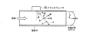
この反射相関型超音波流量計は、図7に示すように、トランスデューサTDから管路TBに流れる流体Fに向けて所定の時間差で照射した2つの超音波Sが、流体Fに含まれる気泡や粒子等の反射物(a、b、c)によって反射して得られる反射波に、相互相関処理を施すことにより管路TBにおける径方向の流速分布を求め、その流速分布から算出した平均流速VMに管路断面積Stを乗算することで流量Qを演算するものである。
As is well known, there is a reflection correlation type ultrasonic flowmeter using a reflection correlation method as one type of flowmeter.
As shown in FIG. 7, this reflection correlation type ultrasonic flowmeter has two ultrasonic waves S irradiated from the transducer TD toward the fluid F flowing in the pipe TB with a predetermined time difference, and bubbles contained in the fluid F A cross-correlation process is performed on the reflected wave obtained by reflection by the reflecting material (a, b, c) such as particles to obtain a radial flow velocity distribution in the pipe TB, and an average flow velocity VM calculated from the flow velocity distribution is obtained. Is multiplied by the pipe cross-sectional area St to calculate the flow rate Q.
一般的に、管路TBの中心付近の流速は速く、管路壁面近傍の流速は遅くなるため、管路TBにおける径方向の位置をxとすると、各位置xに対する流速Vxはxの関数f(x)で表される。つまり、流速分布はVx=f(x)から求めることができる。また、平均流速VMは、Vxを径方向に積分することで算出することができる。このように、反射相関型超音波流量計では、流速分布から平均流速VMを算出することができるため、透過法(伝播時間差法)と比べて精度良く流量Qを計測することができる。
なお、反射相関型超音波流量計に関する先行技術文献としては、下記特許文献1及び2等がある。
In general, since the flow velocity near the center of the pipe TB is high and the flow velocity near the pipe wall surface is slow, assuming that the radial position in the pipe TB is x, the flow velocity Vx for each position x is a function f of x. It is represented by (x). That is, the flow velocity distribution can be obtained from Vx = f (x). Further, the average flow velocity VM can be calculated by integrating Vx in the radial direction. Thus, since the reflection correlation type ultrasonic flowmeter can calculate the average flow velocity VM from the flow velocity distribution, the flow rate Q can be measured with higher accuracy than the transmission method (propagation time difference method).
As prior art documents related to the reflection correlation type ultrasonic flowmeter, there are
ところで、図7に示すように、超音波Sの射出角をθ、平均流速VMの軸流成分(管路TBの軸方向の成分)をVG、偏流成分(管路TBの径方向の成分)をVEとすると、平均流速VMは下記(1)式で表される。
VM = VG・sinθ−VE・cosθ ・・・・(1)
つまり、従来の反射相関型超音波流量計によって流量Qを計測する場合、平均流速VMには誤差要因となる偏流成分VEが含まれることになるため、正確な流量Qを求めることが困難であった。
By the way, as shown in FIG. 7, the emission angle of the ultrasonic wave S is θ, the axial flow component (component in the axial direction of the pipe TB) of the average flow velocity VM is VG, and the drift component (component in the radial direction of the pipe TB). If VE is VE, the average flow velocity VM is expressed by the following equation (1).
VM = VG · sin θ−VE · cos θ (1)
That is, when the flow rate Q is measured by a conventional reflection correlation type ultrasonic flowmeter, the average flow velocity VM includes a drift component VE that causes an error, and thus it is difficult to obtain an accurate flow rate Q. It was.
本発明は、上述した事情に鑑みてなされたものであり、高精度に流体の物理量を計測することが可能な超音波計測器を提供することを目的とする。 The present invention has been made in view of the above-described circumstances, and an object thereof is to provide an ultrasonic measuring instrument capable of measuring a physical quantity of a fluid with high accuracy.
上記課題を解決するために、本発明の超音波計測器は、超音波を用いて管路に流れる流体に関する物理量を計測する超音波計測器であって、前記管路内に超音波を送信する一方、受信した超音波に応じた受信信号を出力する超音波送受信部と、少なくとも2つの超音波が所定の時間差で送信されるように前記超音波送受信部を制御する制御部と、管路壁面で反射される前に流体中の反射物で反射されて受信された少なくとも2つの超音波に対応する受信信号を基に反射相関法を用いて算出した第1の平均流速と、前記管路壁面で反射された後に前記反射物で反射されて受信された少なくとも2つの超音波に対応する受信信号を基に反射相関法を用いて算出した第2の平均流速とに基づいて前記流体の平均流速を算出する信号処理部とを備えることを特徴とする。 In order to solve the above-described problem, an ultrasonic measuring instrument of the present invention is an ultrasonic measuring instrument that measures a physical quantity related to a fluid flowing in a pipe using ultrasonic waves, and transmits the ultrasonic wave into the pipe. On the other hand, an ultrasonic transmission / reception unit that outputs a reception signal corresponding to the received ultrasonic wave, a control unit that controls the ultrasonic transmission / reception unit so that at least two ultrasonic waves are transmitted with a predetermined time difference, and a pipe wall surface A first average flow velocity calculated using a reflection correlation method based on a reception signal corresponding to at least two ultrasonic waves reflected and received by a reflector in the fluid before being reflected by the fluid, and the pipe wall surface And the second average flow velocity calculated using the reflection correlation method based on the reception signals corresponding to the at least two ultrasonic waves reflected and received by the reflector after being reflected by the reflector, and the average flow velocity of the fluid A signal processing unit for calculating And wherein the door.
また、本発明の超音波計測器において、前記信号処理部は、前記第1の平均流速と前記第2の平均流速との加算値を2で除算することにより、前記流体の平均流速を算出することを特徴とする。 In the ultrasonic measuring instrument according to the present invention, the signal processing unit may calculate an average flow velocity of the fluid by dividing an addition value of the first average flow velocity and the second average flow velocity by 2. It is characterized by that.
また、本発明の超音波計測器において、2つの前記超音波送受信部が、前記管路を挟んで互いに超音波の送受信が可能になるように設けられ、前記制御部は、反射相関法使用時には、少なくとも2つの超音波が所定の時間差で送信されるように一方の超音波送受信部を制御し、透過法使用時には、交互に超音波が送受信されるように2つの超音波送受信部を制御し、前記信号処理部は、前記反射相関法使用時に算出した前記流体の平均流速と、前記透過法使用時に2つの超音波送受信部によって交互に超音波が送受信されることで得られる受信信号を基に算出した前記流体の平均流速との関係から流量補正係数を求めることを特徴とする。 Further, in the ultrasonic measuring instrument of the present invention, the two ultrasonic transmission / reception units are provided so as to be able to transmit / receive ultrasonic waves to / from each other across the pipeline, and the control unit is configured to use the reflection correlation method. One ultrasonic transmission / reception unit is controlled so that at least two ultrasonic waves are transmitted at a predetermined time difference, and when using the transmission method, the two ultrasonic transmission / reception units are controlled so that ultrasonic waves are alternately transmitted / received. The signal processing unit is based on an average flow velocity of the fluid calculated when using the reflection correlation method and a received signal obtained by transmitting and receiving ultrasonic waves alternately by two ultrasonic transmission and reception units when using the transmission method. The flow rate correction coefficient is obtained from the relationship with the average flow velocity of the fluid calculated in (1).
また、本発明の超音波計測器において、前記信号処理部は、前記透過法使用時には、透過法を用いて算出した前記流体の平均流速と前記流量補正係数とを基に前記流体の流量を算出することを特徴とする。 In the ultrasonic measuring instrument of the present invention, the signal processing unit calculates the flow rate of the fluid based on the average flow velocity of the fluid and the flow rate correction coefficient calculated using the transmission method when the transmission method is used. It is characterized by doing.
また、本発明の超音波計測器において、前記信号処理部は、透過法を用いて算出した前記流体の平均流速と前記流量補正係数との対応関係を表す対応関係データを作成し、前記透過法使用時には、透過法を用いて算出した前記流体の平均流速に対応する流量補正係数を前記対応関係データから抽出し、該抽出した流量補正係数と前記透過法を用いて算出した前記流体の平均流速とを基に前記流体の流量を算出することを特徴とする。 In the ultrasonic measuring instrument of the present invention, the signal processing unit creates correspondence data representing a correspondence between the average flow velocity of the fluid calculated using a transmission method and the flow rate correction coefficient, and transmits the transmission method. In use, a flow rate correction coefficient corresponding to the average flow velocity of the fluid calculated using a permeation method is extracted from the correspondence data, and the average flow velocity of the fluid calculated using the extracted flow rate correction coefficient and the permeation method is used. Based on the above, the flow rate of the fluid is calculated.
また、本発明の超音波計測器において、前記信号処理部は、前記第1の平均流速と前記第2の平均流速との差分を前記平均流速の偏流成分として求めることを特徴とする。 In the ultrasonic measuring instrument according to the present invention, the signal processing unit obtains a difference between the first average flow velocity and the second average flow velocity as a drift component of the average flow velocity.
本発明によれば、平均流速から誤差要因となる偏流成分を除去することが可能となるため、正確な平均流速を求めることができる。また、そのような正確な平均流速から流量を求めることができるため、流量の計測精度の向上を図ることができる。 According to the present invention, it is possible to remove the drift component that causes an error from the average flow velocity, so that an accurate average flow velocity can be obtained. Further, since the flow rate can be obtained from such an accurate average flow velocity, the measurement accuracy of the flow rate can be improved.
以下、図面を参照して、本発明の一実施形態について説明する。
〔第1実施形態〕
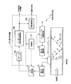
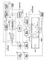
図1は、第1実施形態に係る超音波計測器1の機能構成を示すブロック図である。この図1に示すように、超音波計測器1は、インターバル送信回路11、第1の増幅器12、トランスデューサ13、第2の増幅器14、A/D変換器15、信号処理部16及び制御部17から構成されている。さらに、信号処理部16は、ウォールフィルタ16a、インターバル反射相関演算部16b及び流量演算部16cを備えている。
Hereinafter, an embodiment of the present invention will be described with reference to the drawings.
[First Embodiment]
FIG. 1 is a block diagram showing a functional configuration of the ultrasonic measuring instrument 1 according to the first embodiment. As shown in FIG. 1, the ultrasonic measuring instrument 1 includes an
なお、これら各機能構成要素の内、インターバル送信回路11、第1の増幅器12、トランスデューサ13、第2の増幅器14及びA/D変換器15は、本発明における超音波送受信部に相当するものである。また、第1の増幅器12、第2の増幅器14及びウォールフィルタ16aは、必須の構成要素ではなく、必要に応じて削除しても良いものである。
Of these functional components, the
このような超音波計測器1は、所定の断面形状を有する管路TB内を流れる流体Fの流速分布を演算し、この流速分布から得られる平均流速VMと管路TBの断面積Sとに基づいて流体Fの流量Qを演算する計測器である。また、この超音波計測器1において、ウォールフィルタ16a、インターバル反射相関演算部16b及び流量演算部16cは、ソフトウェア的に信号処理する信号処理部16の機能構成要素である。この信号処理部16の内部メモリには、上記断面積S等、流速分布及び流量Qの演算に必要なパラメータや演算アルゴリズムを規定する演算プログラム(ソフトウェア)が予め記憶されている。
Such an ultrasonic measuring instrument 1 calculates the flow velocity distribution of the fluid F flowing in the pipe TB having a predetermined cross-sectional shape, and calculates the average flow velocity VM obtained from the flow velocity distribution and the cross-sectional area S of the pipe TB. It is a measuring instrument that calculates the flow rate Q of the fluid F based on it. In the ultrasonic measuring instrument 1, the
インターバル送信回路11は、制御部17による制御の下、超音波の周波数帯域、例えば500kHz〜2MkHzの周波数帯域の何れかの周波数fを有すると共に、所定の時間差(タイムインターバルT1)でパルス状(バースト状)に間欠する2つの送信バースト信号を第1の増幅器12に出力する電子回路であり、正弦波発振回路と、該正弦波発振回路が発振した周波数fの正弦波信号(連続信号)を上記タイムインターバルT1で繰り返すバースト信号に強度変調する強度変調回路から構成されている。第1の増幅器12は、インターバル送信回路11から入力された送信バースト信号を所定の増幅度で増幅してトランスデューサ13に出力する。
Under the control of the
トランスデューサ13は、図示するように、管路TBの外表面に設けられており、第1の増幅器12から入力された送信バースト信号を計測用超音波バースト信号USに変換し、流体Fの流れ方向に直交する方向に対して射出角度θで管路TB内に送信(出射)すると共に、流体Fに含まれる気泡や粒子等の反射物で反射された計測用超音波バースト信号USを評価用超音波バースト信号UAとして受信し、その受信した評価用超音波バースト信号UAを電気信号(受信信号)に変換して第2の増幅器14に出力する。
As shown in the figure, the transducer 13 is provided on the outer surface of the pipe TB, converts the transmission burst signal input from the
上記計測用超音波バースト信号USは、第1の増幅器12から入力された送信バースト信号(電気信号)を超音波に変換したものなので、送信バースト信号が有する正弦波の周波数fと同一周波数を有すると共にタイムインターバルT1で繰り返すバースト状の音響信号である。このような計測用超音波バースト信号USは、管路TB内において図1に示す経路(パス)P1に沿って伝播し、管路壁面で反射された後はパスP2に沿って伝播する。
The measurement ultrasonic burst signal US is obtained by converting the transmission burst signal (electric signal) input from the
計測用超音波バースト信号USは、パスP1及びP2を伝播する間に、流体F中の反射物によって反射され、評価用超音波バースト信号UAとしてトランスデューサ13に順次受信される。なお、本実施形態では、説明の便宜上、パスP1上に反射物a、b、cが存在し、パスP2上に反射物d、e、fが存在するものと仮定する。 The ultrasonic burst signal US for measurement is reflected by the reflector in the fluid F while propagating through the paths P1 and P2, and is sequentially received by the transducer 13 as the ultrasonic burst signal UA for evaluation. In the present embodiment, for convenience of explanation, it is assumed that the reflectors a, b, and c exist on the path P1, and the reflectors d, e, and f exist on the path P2.
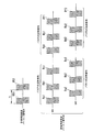
図2は、計測用超音波バースト信号US及び評価用超音波バースト信号UAの波形を示す波形図である。計測用超音波バースト信号USは、周波数fの正弦波である第1の超音波バースト信号US1及び第2の超音波バースト信号US2からなり、これら第1の超音波バースト信号US1と第2の超音波バースト信号US2とはタイムインターバルT1で隣り合う関係に設定されている。 FIG. 2 is a waveform diagram showing waveforms of the measurement ultrasonic burst signal US and the evaluation ultrasonic burst signal UA. The measurement ultrasonic burst signal US includes a first ultrasonic burst signal US1 and a second ultrasonic burst signal US2 which are sine waves having a frequency f, and the first ultrasonic burst signal US1 and the second ultrasonic burst signal US1. The sound wave burst signal US2 is set to be adjacent to each other at the time interval T1.
評価用超音波バースト信号UAは、上記第1の超音波バースト信号US1がパスP1及びP2を伝播する間に、流体F中の反射物a、b、c、d、e、fによって反射されて発生する反射信号Ra1、Rb1、Rc1、Rd1、Re1、Rf1を含む第1の反射超音波バースト信号UA1と、上記第2の超音波バースト信号US2がパスP1及びP2を伝播する間に、流体F中の反射物a、b、c、d、e、fによって反射されて発生する反射信号Ra2、Rb2、Rc2、Rd2、Re2、Rf2を含む第2の反射超音波バースト信号UA2とからなる。このような評価用超音波バースト信号UAは、トランスデューサ13によって受信されることにより第1及び第2の反射超音波バースト信号UA1、UA2に相当する2つのバースト信号(電気信号)からなる受信信号に変換される。 The evaluation ultrasonic burst signal UA is reflected by the reflectors a, b, c, d, e, and f in the fluid F while the first ultrasonic burst signal US1 propagates through the paths P1 and P2. While the first reflected ultrasonic burst signal UA1 including the generated reflected signals Ra1, Rb1, Rc1, Rd1, Re1, Rf1 and the second ultrasonic burst signal US2 propagates through the paths P1 and P2, the fluid F And a second reflected ultrasonic burst signal UA2 including reflected signals Ra2, Rb2, Rc2, Rd2, Re2, and Rf2 generated by being reflected by the reflectors a, b, c, d, e, and f. The evaluation ultrasonic burst signal UA is received by the transducer 13 to be a reception signal composed of two burst signals (electrical signals) corresponding to the first and second reflected ultrasonic burst signals UA1 and UA2. Converted.
第2の増幅器14は、トランスデューサ13から入力された受信信号を所定の増幅度で増幅してA/D変換器15に出力する。A/D変換器15は、上記第2の増幅器14から入力された受信信号(アナログ信号)を、サンプリング定理を満たす所定のサンプリングレート、つまり上記周波数fの2倍以上の繰返し周期でサンプリングすることによりデジタル信号(受信データ)に変換して信号処理部16(詳細にはウォールフィルタ16a)に出力する。
The
信号処理部16のウォールフィルタ16aは、所定のアルゴリズムのフィルタ処理を上記受信データに施すことにより、受信データに含まれる管路TBからの反響成分(ノイズ信号)を除去し、流体F中の気泡や粒子による反射成分のみを含む受信データをインターバル反射相関演算部16bに出力する。
The
インターバル反射相関演算部16bは、ウォールフィルタ16aから入力される受信データを基に反射相関法を用いて相関演算処理を行うことにより気泡や粒子の移動速度の分布、つまり管路TBにおける径方向の流速分布を求め、この流速分布から流体Fの平均流速VMを算出する。このインターバル反射相関演算部16bの演算結果である平均流速VMは、流量演算部16cに出力されると共に超音波計測器1の計測値の1つとして外部に出力される。なお、このようなインターバル反射相関演算部16bの詳細処理については動作説明として後述する。
The interval reflection
流量演算部16cは、インターバル反射相関演算部16bで求められた平均流速VMと管路TBの断面積Sとを乗算することにより流体Fの流量Qを演算する。制御部17は、上述したインターバル送信回路11、A/D変換器15及び信号処理部16を同期制御することにより、インターバル送信回路11における送信バースト信号の発生タイミングに同期して受信信号をA/D変換器15で受信データに変換させると共に該受信データを信号処理部16で演算処理させる。
The flow
次に、上記のように構成された第1実施形態に係る超音波計測器1の詳細動作について、図3、図4を参照して説明する。 Next, detailed operation of the ultrasonic measuring instrument 1 according to the first embodiment configured as described above will be described with reference to FIGS. 3 and 4.
インターバル送信回路11は、制御部17から測定開始を示す送信指示信号が入力されると、上述した送信バースト信号を第1の増幅器12に出力する。この送信バースト信号は、第1の増幅器12で増幅された後、トランスデューサ13に入力されて超音波に変換されて、図2に示すような計測用超音波バースト信号USとして管路TB内に出射される。この計測用超音波バースト信号USは、パスP1及びパスP2を伝播する間に、管路TB内を上流から下流に向かって流れる流体F中の反射物a〜fによって反射され、評価用超音波バースト信号UAとしてトランスデューサ13に受信される。
The
すなわち、トランスデューサ13は、計測用超音波バースト信号USにおける第1の超音波バースト信号US1が反射物a〜fによって反射されて発生する反射信号Ra1〜Rf1を含む第1の反射超音波バースト信号UA1と、同じく計測用超音波バースト信号USにおける第2の超音波バースト信号US2が反射物a〜fによって反射されて発生する反射信号Ra2〜Rf2を含む第2の反射超音波バースト信号UA2とからなる評価用超音波バースト信号UAを受信信号に変換して第2の増幅器14に出力する。
That is, the transducer 13 includes the first reflected ultrasonic burst signal UA1 including the reflected signals Ra1 to Rf1 that are generated when the first ultrasonic burst signal US1 in the measurement ultrasonic burst signal US is reflected by the reflectors a to f. And a second reflected ultrasonic burst signal UA2 including reflected signals Ra2 to Rf2 generated when the second ultrasonic burst signal US2 in the measurement ultrasonic burst signal US is reflected by the reflectors a to f. The evaluation ultrasonic burst signal UA is converted into a reception signal and output to the
この受信信号は、評価用超音波バースト信号UAを電気信号に変換したものなので、信号として第1及び第2の反射超音波バースト信号UA1、UA2と同様な情報を内包する信号である。このような受信信号(アナログ信号)は、A/D変換器15によって受信データ(デジタル信号)に変換されてウォールフィルタ16aに入力されるが、A/D変換器15における量子化処理は、サンプリング定理を満足するものなので、受信データは上記受信信号と同様な情報を内包する信号である。
Since this received signal is obtained by converting the ultrasonic burst signal UA for evaluation into an electrical signal, it is a signal that contains the same information as the first and second reflected ultrasonic burst signals UA1 and UA2 as signals. Such a reception signal (analog signal) is converted into reception data (digital signal) by the A /
このような受信データは、ウォールフィルタ16aによって上述したフィルタ処理が施されることにより、流体F中の反射物によって反射された信号成分のみを含む信号となり、インターバル反射相関演算部16bに入力される。インターバル反射相関演算部16bは、
ウォールフィルタ16aから入力される受信データ(つまり、第1及び第2の反射超音波バースト信号UA1、UA2からなる評価用超音波バースト信号UAを示すデータ)を基に、反射相関法を用いて相関演算処理を行うことにより管路TBにおける径方向の流速分布を求め、この流速分布から流体Fの平均流速VMを算出する。
Such received data is subjected to the filtering process described above by the
Based on the reception data input from the
具体的には、インターバル反射相関演算部16bは、まず、管路壁面で反射される前、つまりパスP1を伝播する間に流体F中の反射物で反射されて受信された2つの超音波に対応する受信信号を基に相関演算処理を行うことにより、パスP1についての流速分布を求め、その流速分布から平均流速VM1を算出する。つまり、インターバル反射相関演算部16bは、第1の反射超音波バースト信号UA1からパスP1を伝播する間に得られた反射超音波、つまり反射信号Ra1、Rb1、Rc1を抽出すると共に、第2の反射超音波バースト信号UA2からパスP1を伝播する間に得られた反射超音波、つまり反射信号Ra2、Rb2、Rc2を抽出する。
Specifically, the interval reflection
そして、インターバル反射相関演算部16bは、反射信号Ra1とRa2との相関演算処理、反射信号Rb1とRb2との相関演算処理、反射信号Rc1とRc2との相関演算処理を行うことで、反射物a、b、cのそれぞれの位置(管路TBにおける径方向の位置)における流速Va、Vb、Vcを求める。
The interval reflection
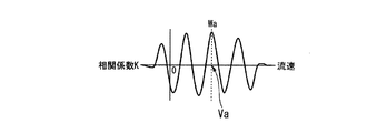
周知のように、相関演算処理とは、演算対象となる2つの信号の時間軸上での相対位置関係を順次オフセットさせて相関係数を演算することを指す。図3は、反射信号Ra1とRa2との相関演算処理を行うことで得られる相関係数Kを表したものである。図3において、横軸は流体Fの流速を示す。この図3に示すように、相関係数Kは正弦波状に変化するが、最も相関係数Kが高いピーク点Waに対応する流速が反射物aの位置における流速Vaとして求めることができる。同様に、インターバル反射相関演算部16bは、反射信号Rb1とRb2との相関係数K、反射信号Rc1とRc2との相関係数Kを求めることにより、反射物b、cのそれぞれの位置における流速Vb、Vcを求める。
As is well known, the correlation calculation processing refers to calculating a correlation coefficient by sequentially offsetting the relative positional relationship between two signals to be calculated on the time axis. FIG. 3 shows a correlation coefficient K obtained by performing a correlation calculation process between the reflected signals Ra1 and Ra2. In FIG. 3, the horizontal axis indicates the flow rate of the fluid F. As shown in FIG. 3, the correlation coefficient K changes sinusoidally, but the flow velocity corresponding to the peak point Wa having the highest correlation coefficient K can be obtained as the flow velocity Va at the position of the reflector a. Similarly, the interval reflection
インターバル反射相関演算部16bは、上記のように求めた流速Va、Vb、VcからパスP1についての流速分布を求める。すなわち、管路TBにおける径方向の位置をxとすると、各位置xに対する流速Vxはxの関数f(x)で表される。つまり、流速分布はVx=f(x)で表すことができる。そして、インターバル反射相関演算部16bは、Vxを径方向に積分することにより、パスP1についての平均流速(第1の平均流速)VM1を算出する。
The interval reflection
続いて、インターバル反射相関演算部16bは、管路壁面で反射された後、つまりパスP2を伝播する間に流体F中の反射物で反射されて受信された2つの超音波に対応する受信信号を基に相関演算処理を行うことにより、パスP2についての流速分布を求め、その流速分布から平均流速(第2の平均流速)VM2を算出する。
Subsequently, the interval reflection
つまり、インターバル反射相関演算部16bは、第1の反射超音波バースト信号UA1からパスP2を伝播する間に得られた反射超音波、つまり反射信号Rd1、Re1、Rf1を抽出すると共に、第2の反射超音波バースト信号UA2からパスP2を伝播する間に得られた反射超音波、つまり反射信号Rd2、Re2、Rf2を抽出する。
That is, the interval reflection
そして、インターバル反射相関演算部16bは、パスP1と同様に、反射信号Rd1とRd2との相関演算処理、反射信号Re1とRe2との相関演算処理、反射信号Rf1とRf2との相関演算処理を行うことで、反射物d、e、fのそれぞれの位置における流速Vd、Ve、Vfを求める。インターバル反射相関演算部16bは、上記のように求めた流速Vd、Ve、VfからパスP2についての流速分布Vxを求め、Vxを径方向に積分することにより、パスP2についての平均流速VM2を算出する。
Then, similarly to the path P1, the interval reflection
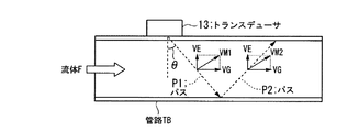
そして、インターバル反射相関演算部16bは、上記のように求めたパスP1についての平均流速VM1と、パスP2についての平均流速VM2とを加算することで流体Fの平均流速VMを算出する。ここで、図4に示すように、計測用超音波バースト信号USの射出角をθ、平均流速VMの軸流成分(管路TBの軸方向の成分)をVG、偏流成分(管路TBの径方向の成分)をVEとすると、パスP1についての平均流速VM1は下記(2)式で表され、パスP2についての平均流速VM2は下記(3)式で表される。
VM1 = VG・sinθ−VE・cosθ ・・・・(2)
VM2 = VG・sinθ+VE・cosθ ・・・・(3)
Then, the interval reflection
VM1 = VG · sin θ−VE · cos θ (2)
VM2 = VG · sin θ + VE · cos θ (3)
つまり、パスP1についての平均流速VM1と、パスP2についての平均流速VM2とを加算することにより、誤差要因となる偏流成分VEが除去され、正確な平均流速VMを得ることができる。なお、上記(2)、(3)式からわかるように、VM1とVM2とを単純に加算すると、VM=2・VG・sinθとなるため、VMを2で除算することで平均化処理する必要がある。 That is, by adding the average flow velocity VM1 for the path P1 and the average flow velocity VM2 for the path P2, the drift component VE that is an error factor is removed, and an accurate average flow velocity VM can be obtained. As can be seen from the above formulas (2) and (3), when VM1 and VM2 are simply added, VM = 2 · VG · sinθ, so it is necessary to perform an averaging process by dividing VM by 2 There is.
一方、流量演算部16cは、インターバル反射相関演算部16bによって算出された平
均流速VMと管路TBの断面積Stとを乗算することで流体Fの流量Qを演算し、外部に計測結果として出力する。
On the other hand, the flow
以上説明したように、第1実施形態に係る超音波計測器1によれば、誤差要因となる偏流成分VEを除去した正確な平均流速VMを算出することができ、その結果、流体Fの流量Qを高精度に計測することが可能となる。 As described above, according to the ultrasonic measuring instrument 1 according to the first embodiment, it is possible to calculate the accurate average flow velocity VM from which the drift component VE that causes an error is removed, and as a result, the flow rate of the fluid F Q can be measured with high accuracy.
〔第2実施形態〕
次に、本発明に係る超音波計測器の第2実施形態について説明する。上記第1実施形態の超音波計測器1では反射相関法を利用するため、反射物を含まないような流体Fが管路TBを流れる場合には流量Qを計測することが困難である。これに対して、第2実施形態では、反射物の有無に関わらず流量Qを正確に計測可能な超音波計測器を提示するものである。
[Second Embodiment]
Next, a second embodiment of the ultrasonic measuring instrument according to the present invention will be described. Since the ultrasonic measuring instrument 1 of the first embodiment uses the reflection correlation method, it is difficult to measure the flow rate Q when a fluid F that does not include a reflector flows through the pipe TB. On the other hand, in 2nd Embodiment, the ultrasonic measuring device which can measure the flow volume Q correctly irrespective of the presence or absence of a reflector is shown.
図5は、第2実施形態に係る超音波計測器2のブロック構成図である。なお、図5において、図1(第1実施形態)と同様の構成要素には同一符号を付して説明を省略する。この図5に示すように、第2実施形態に係る超音波計測器2は、第3の増幅器21、トランスデューサ22、第4の増幅器23、A/D変換器24、透過法演算部16d、流量補正係数演算部16e及び補正係数記憶部16fを新たに備えている。なお、透過法演算部16d、流量補正係数演算部16e及び補正係数記憶部16fは、信号処理部16’の機能構成要素である。
FIG. 5 is a block configuration diagram of the
また、第2実施形態におけるインターバル送信回路11’は、第1実施形態で説明した機能の他、制御部17’による制御の下、透過法(伝播時間差法)使用時には、トランスデューサ13とトランスデューサ22との間で、交互に超音波が送受信されるように送信バースト信号を生成して第1の増幅器12と第3の増幅器21とに出力する。つまり、このインターバル送信回路11’は、透過法(伝播時間差法)使用時には、1つ目の送信バースト信号を第1の増幅器12に出力した後、所定時間の経過後に2つ目の送信バースト信号を第3の増幅器21に出力する。
In addition to the functions described in the first embodiment, the
第3の増幅器21は、インターバル送信回路11’から入力された送信バースト信号を所定の増幅度で増幅してトランスデューサ22に出力する。トランスデューサ22は、トランスデューサ13に対して管路TBを挟んで対向する位置に配置されており、第3の増幅器21から入力された送信バースト信号を透過用超音波バースト信号USaに変換し、流体Fの流れ方向に直交する方向に対して射出角度θでトランスデューサ13に向けて送信(出射)すると共に、トランスデューサ13から送信された透過用超音波バースト信号USbを受信し、その受信した透過用超音波バースト信号USbを電気信号(受信信号)に変換して第4の増幅器23に出力する。
The
第4の増幅器23は、トランスデューサ22から入力された受信信号を所定の増幅度で増幅してA/D変換器24に出力する。A/D変換器24は、上記第4の増幅器23から入力された受信信号(アナログ信号)を、サンプリング定理を満たす所定のサンプリングレートでサンプリングすることによりデジタル信号(受信データ)に変換して信号処理部16’(詳細には透過法演算部16d)に出力する。
The
信号処理部16’の透過法演算部16dは、A/D変換器15及びA/D変換器24から出力される受信データを入力とし、透過法使用時にトランスデューサ13とトランスデューサ22との間で交互に超音波が送受信されることで、A/D変換器15及びA/D変換器24から得られる受信データを基に透過法を用いて流体Fの平均流速VM’を算出して流量演算部16c’及び流量補正係数演算部16eに出力する。
The transmission method calculation unit 16d of the
流量補正係数演算部16eは、透過法演算部16dによって算出された平均流速VM’と、インターバル反射相関演算部16bによって算出された平均流速VMとの関係から流量補正係数Cを算出し、補正係数記憶部16fに記憶させる。補正係数記憶部16fは、流量補正係数演算部16eの要求に応じて流量補正係数Cを記憶する一方、流量演算部16c’の要求に応じて流量補正係数Cを流量演算部16c’に出力する。
The flow rate correction
流量演算部16c’は、反射相関法使用時には、インターバル反射相関演算部16bによって算出された平均流速VMから流体Fの流量Qを算出する一方、透過法使用時には、透過法演算部16dによって算出された平均流速VM’と、補正係数記憶部16fに記憶されている流量補正係数Cとを基に流量Qを算出する。
The flow
制御部17’は、反射相関法使用時には、第1実施形態で説明したように、インターバル送信回路11’、A/D変換器15及び信号処理部16’(ウォールフィルタ16a、インターバル反射相関演算部16b及び流量演算部16c’)を同期制御する一方、透過法使用時には、トランスデューサ13とトランスデューサ22との間で交互に超音波が送受信されるように、インターバル送信回路11’、A/D変換器15、A/D変換器24及び信号処理部16’(透過法演算部16d、流量補正係数演算部16e及び流量演算部16c’)を同期制御する。
When the reflection correlation method is used, the
次に、上記のように構成された第2実施形態に係る超音波計測器2の動作について説明する。
制御部17’は、測定開始タイミングが到来すると、まず、反射相関法を使用して平均流速VMを求めるために、第1実施形態と同様に、インターバル送信回路11’に対して、タイムインターバルT1を有する送信バースト信号を第1の増幅器12に出力するように指示する。以下の動作は第1実施形態と同様なので説明を省略するが、これにより、信号処理部16’のインターバル反射相関演算部16bによって平均流速VMが算出され、流速演算部16cによって流量Qが算出される。
Next, the operation of the
When the measurement start timing arrives, the
上記のように反射相関法を用いて平均流速VM及び流量Qが算出されると、制御部17’は、透過法を使用して平均流速VM’を求めるために、インターバル送信回路11’に対して、トランスデューサ13とトランスデューサ22との間で、交互に超音波が送受信されるように送信バースト信号を生成して第1の増幅器12と第3の増幅器21とに出力する。つまり、このインターバル送信回路11’は、透過法使用時には、1つ目の送信バースト信号を第1の増幅器12に出力した後、所定時間の経過後に2つ目の送信バースト信号を第3の増幅器21に出力する。
When the average flow velocity VM and the flow rate Q are calculated using the reflection correlation method as described above, the
トランスデューサ13は、1つ目の送信バースト信号に応じた透過用超音波バースト信号USbをパスP1に沿ってトランスデューサ22に向けて出射(送信)する。一方、トランスデューサ22は、トランスデューサ13から送信された透過用超音波バースト信号USbを受信し、その受信した透過用超音波バースト信号USbを受信信号に変換して第4の増幅器23に出力する。第4の増幅器23によって増幅された受信信号はA/D変換器24に入力されて受信データに変換された後、透過法演算部16dに出力される。
The transducer 13 emits (transmits) the transmission ultrasonic burst signal USb corresponding to the first transmission burst signal toward the transducer 22 along the path P1. On the other hand, the transducer 22 receives the transmission ultrasonic burst signal USb transmitted from the transducer 13, converts the received transmission ultrasonic burst signal USb into a reception signal, and outputs the received signal to the
また、トランスデューサ22は、2つ目の送信バースト信号に応じた透過用超音波バースト信号USaをパスP1に沿ってトランスデューサ13に向けて出射(送信)する。一方、トランスデューサ13は、トランスデューサ22から送信された透過用超音波バースト信号USaを受信し、その受信した透過用超音波バースト信号USaを受信信号に変換して第2の増幅器14に出力する。第2の増幅器14によって増幅された受信信号はA/D変換器15に入力されて受信データに変換された後、透過法演算部16dに出力される。
Further, the transducer 22 emits (transmits) the transmission ultrasonic burst signal USa corresponding to the second transmission burst signal toward the transducer 13 along the path P1. On the other hand, the transducer 13 receives the transmission ultrasonic burst signal USa transmitted from the transducer 22, converts the received transmission ultrasonic burst signal USa into a reception signal, and outputs the received signal to the
透過法演算部16dは、A/D変換器15及び24から入力される受信データを基に、透過法を用いて平均流速VM’を算出する。つまり、透過法演算部16dは、上流側のトランスデューサ13から下流側のトランスデューサ22へ向けて送信された透過用超音波バースト信号USbの伝播時間と、下流側のトランスデューサ22から上流側のトランスデューサ13へ向けて送信された透過用超音波バースト信号USaの伝播時間との差(伝播時間差)から平均流速VM’を算出する。なお、このような透過法を用いた平均流速VM’の算出手法は公知の技術であるため、詳細な説明を省略する。
The transmission method calculation unit 16d calculates the average flow velocity VM ′ using the transmission method based on the reception data input from the A /
そして、流量補正係数演算部16eは、透過法演算部16dによって算出された平均流速VM’と、インターバル反射相関演算部16bによって算出された平均流速VMとの関係から流量補正係数Cを算出し、補正係数記憶部16fに記憶させる。具体的には、流量補正係数演算部16eは、下記(4)式を基に流量補正係数Cを算出する。
C = VM/VM’ ・・・・(4)
Then, the flow rate correction
C = VM / VM ′ (4)
ここで、透過法演算部16dによって算出された平均流速VM’は、流速分布から得られた値ではないため、正確な平均流速を示すものではない。従って、従来では、透過法を用いて流量Qを求める場合、予め実験等を実施することで得た流量補正係数を平均流速に乗ずることにより、流量Qを補正していた。本実施形態では、インターバル反射相関演算部16bによって算出された平均流速VMは、流速分布から得られた値で且つ偏流成分が除去されているため、正確な平均流速を示しており、この平均流速VMと透過法を用いて算出した平均流速VM’との関係から、予め実験等を実施することなく、容易に正確な流量補正係数Cを求めることが可能となる。
Here, the average flow velocity VM ′ calculated by the permeation method calculation unit 16d is not a value obtained from the flow velocity distribution, and thus does not indicate an accurate average flow velocity. Therefore, conventionally, when the flow rate Q is obtained using the permeation method, the flow rate Q is corrected by multiplying the average flow velocity by a flow rate correction coefficient obtained by conducting an experiment or the like in advance. In the present embodiment, the average flow velocity VM calculated by the interval reflection
流量演算部16c’は、反射相関法使用時には、インターバル反射相関演算部16bによって算出された平均流速VMから流体Fの流量Qを算出する一方、透過法使用時には、透過法演算部16dによって算出された平均流速VM’と、補正係数記憶部16fに記憶されている流量補正係数Cとを基に流量Qを算出する。
The flow
このように、第2実施形態に係る超音波計測器2によれば、流体Fに反射物が含まれており、反射相関法を使用することができる場合には、インターバル反射相関演算部16bによって算出された平均流速VMから流体Fの流量Qを算出することで、正確な流量Qを得ることができる。一方、流体Fに反射物が含まれておらず、反射相関法を使用することができない場合には、透過法演算部16dによって算出された平均流速VM’と、補正係数記憶部16fに記憶されている流量補正係数Cとを基に流量Qを算出することで、正確な流量Qを得ることができる。
As described above, according to the
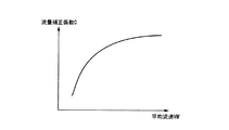
なお、反射相関法を使用できる頻度が少ない場合、図6に示すように、透過法を用いて算出した平均流速VM’と流量補正係数Cとの対応関係を表す対応関係データをマッピング(作成)して、補正係数記憶部16fに記憶させる機能を透過法演算部16dに設け、透過法使用時には、透過法を用いて算出した平均流速VM’に対応する流量補正係数Cを上記の対応関係データから抽出し、該抽出した流量補正係数Cと透過法を用いて算出した平均流速VM’とを基に流体Fの流量Qを算出する機能を流量演算部16c’に設けても良い。これにより、平均流速VM’に対応する流量補正係数Cをより正確に求めることが可能となり、流量Qの計測精度の向上に寄与する。
If the frequency at which the reflection correlation method can be used is low, mapping (creating) correspondence data representing the correspondence between the average flow velocity VM ′ calculated using the transmission method and the flow rate correction coefficient C as shown in FIG. Then, the function to be stored in the correction
また、上記第1及び第2実施形態では、インターバル反射相関演算部16bによって平均流速VMを算出する際、パスP1についての平均流速VM1と、パスP2についての平均流速VM2とを加算して平均化したが、上記(2)及び(3)式からわかるように、パスP1についての平均流速VM1とパスP2についての平均流速VM2との差分をとることにより、誤差要因となる偏流成分を求めることができる。よって、このように求めた偏流成分を不図示の記憶部に記憶しておき、外部に出力するような機能を設けることにより、管路TBを流れる流体Fの振る舞いを解析する際に役立てることが可能となる。
In the first and second embodiments, when the average flow velocity VM is calculated by the interval reflection
1、2…超音波計測器、11、11’…インターバル送信回路、12…第1の増幅器、13、22…トランスデューサ、14…第2の増幅器、15、24…A/D変換器、16、16’…信号処理部、17、17’…制御部、16a…ウォールフィルタ、16b…インターバル反射相関演算部、16c、16c’…流量演算部、21…第3の増幅器、23…第4の増幅器、16d…透過法演算部、16e…流量補正係数演算部、16f…補正係数記憶部、TB…管路、F…流体
DESCRIPTION OF
Claims (6)
前記管路内に超音波を送信する一方、受信した超音波に応じた受信信号を出力する超音
波送受信部と、
少なくとも2つの超音波が所定の時間差で送信されるように前記超音波送受信部を制御する制御部と、
管路壁面で反射される前に流体中の反射物で反射されて受信された少なくとも2つの超音波に対応する受信信号を基に反射相関法を用いて算出した第1の平均流速と、前記管路壁面で反射された後に前記反射物で反射されて受信された少なくとも2つの超音波に対応する受信信号を基に反射相関法を用いて算出した第2の平均流速とに基づいて前記流体の平均流速を算出する信号処理部と
を備えることを特徴とする超音波計測器。 An ultrasonic measuring instrument that measures a physical quantity related to a fluid flowing in a pipeline using ultrasonic waves,
An ultrasonic transmission / reception unit that transmits an ultrasonic wave in the pipe line and outputs a reception signal corresponding to the received ultrasonic wave;
A control unit that controls the ultrasonic transmission / reception unit so that at least two ultrasonic waves are transmitted at a predetermined time difference;
A first average flow velocity calculated using a reflection correlation method based on a reception signal corresponding to at least two ultrasonic waves reflected and received by a reflector in a fluid before being reflected by a pipe wall surface; The fluid based on a second average flow velocity calculated using a reflection correlation method based on a reception signal corresponding to at least two ultrasonic waves reflected and received by the reflector after being reflected by a pipe wall surface An ultrasonic measuring instrument comprising: a signal processing unit that calculates an average flow velocity of
前記制御部は、反射相関法使用時には、少なくとも2つの超音波が所定の時間差で送信されるように一方の超音波送受信部を制御し、透過法使用時には、交互に超音波が送受信されるように2つの超音波送受信部を制御し、
前記信号処理部は、前記反射相関法使用時に算出した前記流体の平均流速と、前記透過法使用時に2つの超音波送受信部によって交互に超音波が送受信されることで得られる受信信号を基に算出した前記流体の平均流速との関係から流量補正係数を求めることを特徴とする請求項1または2に記載の超音波計測器。 Two ultrasonic transmission / reception units are provided so as to be able to transmit / receive ultrasonic waves to / from each other across the pipeline,
The control unit controls one ultrasonic transmission / reception unit so that at least two ultrasonic waves are transmitted at a predetermined time difference when using the reflection correlation method, and alternately transmits and receives ultrasonic waves when using the transmission method. To control two ultrasonic transmitters and receivers,
The signal processing unit is based on an average flow velocity of the fluid calculated when using the reflection correlation method and a reception signal obtained by transmitting and receiving ultrasonic waves alternately by two ultrasonic transmission and reception units when using the transmission method. The ultrasonic measuring instrument according to claim 1, wherein a flow rate correction coefficient is obtained from the calculated relationship with the average flow velocity of the fluid.
Priority Applications (1)
| Application Number | Priority Date | Filing Date | Title |
|---|---|---|---|
| JP2009026120A JP5321106B2 (en) | 2009-02-06 | 2009-02-06 | Ultrasonic measuring instrument |
Applications Claiming Priority (1)
| Application Number | Priority Date | Filing Date | Title |
|---|---|---|---|
| JP2009026120A JP5321106B2 (en) | 2009-02-06 | 2009-02-06 | Ultrasonic measuring instrument |
Publications (2)
| Publication Number | Publication Date |
|---|---|
| JP2010181326A JP2010181326A (en) | 2010-08-19 |
| JP5321106B2 true JP5321106B2 (en) | 2013-10-23 |
Family
ID=42762973
Family Applications (1)
| Application Number | Title | Priority Date | Filing Date |
|---|---|---|---|
| JP2009026120A Expired - Fee Related JP5321106B2 (en) | 2009-02-06 | 2009-02-06 | Ultrasonic measuring instrument |
Country Status (1)
| Country | Link |
|---|---|
| JP (1) | JP5321106B2 (en) |
Cited By (7)
| Publication number | Priority date | Publication date | Assignee | Title |
|---|---|---|---|---|
| US8623247B2 (en) | 2003-06-19 | 2014-01-07 | Eastman Chemical Company | Process of making water-dispersible multicomponent fibers from sulfopolyesters |
| US8691130B2 (en) | 2003-06-19 | 2014-04-08 | Eastman Chemical Company | Process of making water-dispersible multicomponent fibers from sulfopolyesters |
| US8840757B2 (en) | 2012-01-31 | 2014-09-23 | Eastman Chemical Company | Processes to produce short cut microfibers |
| US9273417B2 (en) | 2010-10-21 | 2016-03-01 | Eastman Chemical Company | Wet-Laid process to produce a bound nonwoven article |
| US9303357B2 (en) | 2013-04-19 | 2016-04-05 | Eastman Chemical Company | Paper and nonwoven articles comprising synthetic microfiber binders |
| US9598802B2 (en) | 2013-12-17 | 2017-03-21 | Eastman Chemical Company | Ultrafiltration process for producing a sulfopolyester concentrate |
| US9605126B2 (en) | 2013-12-17 | 2017-03-28 | Eastman Chemical Company | Ultrafiltration process for the recovery of concentrated sulfopolyester dispersion |
Families Citing this family (2)
| Publication number | Priority date | Publication date | Assignee | Title |
|---|---|---|---|---|
| JP5447561B2 (en) | 2012-03-08 | 2014-03-19 | 横河電機株式会社 | Ultrasonic measuring instrument |
| JP6472617B2 (en) * | 2014-08-06 | 2019-02-20 | 関西電力株式会社 | External ultrasonic flowmeter for gas and gas flow measurement method |
Family Cites Families (9)
| Publication number | Priority date | Publication date | Assignee | Title |
|---|---|---|---|---|
| JPS5852487Y2 (en) * | 1979-01-19 | 1983-11-30 | 横河電機株式会社 | Flow rate measurement device using correlation technology |
| JPS5852488Y2 (en) * | 1979-01-19 | 1983-11-30 | 横河電機株式会社 | Flow rate measurement device using correlation technology |
| JP2002340644A (en) * | 2001-05-15 | 2002-11-27 | Hironari Kikura | Ultrasonic flow and flow velocity-measuring instrument and ultrasonic flow and flow velocity-measuring method |
| JP3669580B2 (en) * | 2002-05-24 | 2005-07-06 | 学校法人慶應義塾 | Ultrasonic flow velocity distribution and flow meter |
| JP2005181268A (en) * | 2003-12-24 | 2005-07-07 | Yokogawa Electric Corp | Ultrasonic flowmeter |
| WO2005083370A1 (en) * | 2004-02-26 | 2005-09-09 | Fuji Electric Systems Co., Ltd. | Ultrasonic flowmeter and ultrasonic flow rate measurement method |
| JP2008157677A (en) * | 2006-12-21 | 2008-07-10 | Tokyo Electric Power Co Inc:The | System and method for measuring quantity of flow, computer program, and ultrasonic transducer |
| JP4953001B2 (en) * | 2007-03-29 | 2012-06-13 | 東京電力株式会社 | Flow rate measuring device, flow rate measuring method, and computer program |
| JP4983787B2 (en) * | 2008-12-24 | 2012-07-25 | 横河電機株式会社 | Ultrasonic measuring instrument |
-
2009
- 2009-02-06 JP JP2009026120A patent/JP5321106B2/en not_active Expired - Fee Related
Cited By (12)
| Publication number | Priority date | Publication date | Assignee | Title |
|---|---|---|---|---|
| US8623247B2 (en) | 2003-06-19 | 2014-01-07 | Eastman Chemical Company | Process of making water-dispersible multicomponent fibers from sulfopolyesters |
| US8691130B2 (en) | 2003-06-19 | 2014-04-08 | Eastman Chemical Company | Process of making water-dispersible multicomponent fibers from sulfopolyesters |
| US9273417B2 (en) | 2010-10-21 | 2016-03-01 | Eastman Chemical Company | Wet-Laid process to produce a bound nonwoven article |
| US8840757B2 (en) | 2012-01-31 | 2014-09-23 | Eastman Chemical Company | Processes to produce short cut microfibers |
| US8840758B2 (en) | 2012-01-31 | 2014-09-23 | Eastman Chemical Company | Processes to produce short cut microfibers |
| US8871052B2 (en) | 2012-01-31 | 2014-10-28 | Eastman Chemical Company | Processes to produce short cut microfibers |
| US8882963B2 (en) | 2012-01-31 | 2014-11-11 | Eastman Chemical Company | Processes to produce short cut microfibers |
| US8906200B2 (en) | 2012-01-31 | 2014-12-09 | Eastman Chemical Company | Processes to produce short cut microfibers |
| US9175440B2 (en) | 2012-01-31 | 2015-11-03 | Eastman Chemical Company | Processes to produce short-cut microfibers |
| US9303357B2 (en) | 2013-04-19 | 2016-04-05 | Eastman Chemical Company | Paper and nonwoven articles comprising synthetic microfiber binders |
| US9598802B2 (en) | 2013-12-17 | 2017-03-21 | Eastman Chemical Company | Ultrafiltration process for producing a sulfopolyester concentrate |
| US9605126B2 (en) | 2013-12-17 | 2017-03-28 | Eastman Chemical Company | Ultrafiltration process for the recovery of concentrated sulfopolyester dispersion |
Also Published As
| Publication number | Publication date |
|---|---|
| JP2010181326A (en) | 2010-08-19 |
Similar Documents
| Publication | Publication Date | Title |
|---|---|---|
| JP5321106B2 (en) | Ultrasonic measuring instrument | |
| JP6682500B2 (en) | Signal transit time difference type flow meter | |
| JP6727308B2 (en) | Improved beam shaping acoustic signal propagation time difference type flow meter | |
| JP4983787B2 (en) | Ultrasonic measuring instrument | |
| JP4135056B2 (en) | Ultrasonic flow meter | |
| JP5447561B2 (en) | Ultrasonic measuring instrument | |
| JPWO2005083370A1 (en) | Ultrasonic flow meter and ultrasonic flow measuring method | |
| JP2005241546A (en) | Doppler ultrasonic flowmeter, processing device thereof and program | |
| JP7445666B2 (en) | Ultrasound echo processing when there is a Doppler shift | |
| US7806003B2 (en) | Doppler type ultrasonic flow meter | |
| JP5231278B2 (en) | Ultrasonic flow meter | |
| JP6187343B2 (en) | Ultrasonic measuring instrument | |
| JPH11351928A (en) | Flowmetr and flow rate measuring method | |
| JP5316795B2 (en) | Ultrasonic measuring instrument | |
| JP2010101767A (en) | Ultrasonic flowmeter | |
| RU2313068C2 (en) | Mode of measuring gas consumption in main pipelines and an arrangement for its execution | |
| RU2447406C1 (en) | Ultrasonic method of measuring liquid and gaseous media and apparatus for realising said method | |
| RU86759U1 (en) | ACOUSTIC RANGE DETERMINATION DEVICE | |
| RU2333499C2 (en) | Acoustic method of determining liquid or gas flow direction and velocity variation and device (versions) to this effect | |
| JP2005195372A (en) | Ultrasonic flowmeter, and wedge used for ultrasonic flowmeter |
Legal Events
| Date | Code | Title | Description |
|---|---|---|---|
| A621 | Written request for application examination |
Free format text: JAPANESE INTERMEDIATE CODE: A621 Effective date: 20111118 |
|
| A977 | Report on retrieval |
Free format text: JAPANESE INTERMEDIATE CODE: A971007 Effective date: 20130327 |
|
| TRDD | Decision of grant or rejection written | ||
| A01 | Written decision to grant a patent or to grant a registration (utility model) |
Free format text: JAPANESE INTERMEDIATE CODE: A01 Effective date: 20130618 |
|
| A61 | First payment of annual fees (during grant procedure) |
Free format text: JAPANESE INTERMEDIATE CODE: A61 Effective date: 20130701 |
|
| R150 | Certificate of patent or registration of utility model |
Free format text: JAPANESE INTERMEDIATE CODE: R150 |
|
| LAPS | Cancellation because of no payment of annual fees |