EP1719087B1 - Procede et appareil pour communiquer l'existence d'une situation d'urgence sans identifier de facon unique la source de la communication - Google Patents
Procede et appareil pour communiquer l'existence d'une situation d'urgence sans identifier de facon unique la source de la communication Download PDFInfo
- Publication number
- EP1719087B1 EP1719087B1 EP05702878A EP05702878A EP1719087B1 EP 1719087 B1 EP1719087 B1 EP 1719087B1 EP 05702878 A EP05702878 A EP 05702878A EP 05702878 A EP05702878 A EP 05702878A EP 1719087 B1 EP1719087 B1 EP 1719087B1
- Authority
- EP
- European Patent Office
- Prior art keywords
- predetermined
- sequence
- signal
- antenna
- frequency
- Prior art date
- Legal status (The legal status is an assumption and is not a legal conclusion. Google has not performed a legal analysis and makes no representation as to the accuracy of the status listed.)
- Not-in-force
Links
- 238000004891 communication Methods 0.000 title claims abstract description 25
- 238000000034 method Methods 0.000 title claims description 32
- 230000005540 biological transmission Effects 0.000 claims description 44
- 230000005684 electric field Effects 0.000 claims description 22
- 230000004044 response Effects 0.000 claims description 18
- 238000012545 processing Methods 0.000 claims description 7
- 238000012544 monitoring process Methods 0.000 claims description 5
- 230000003213 activating effect Effects 0.000 claims description 3
- 238000004804 winding Methods 0.000 claims 2
- 230000003595 spectral effect Effects 0.000 description 8
- 238000001228 spectrum Methods 0.000 description 6
- 239000003990 capacitor Substances 0.000 description 4
- 230000008901 benefit Effects 0.000 description 3
- 230000001360 synchronised effect Effects 0.000 description 3
- 238000012935 Averaging Methods 0.000 description 2
- 235000008694 Humulus lupulus Nutrition 0.000 description 2
- 238000010586 diagram Methods 0.000 description 2
- 238000001914 filtration Methods 0.000 description 2
- 238000012986 modification Methods 0.000 description 2
- 230000004048 modification Effects 0.000 description 2
- 230000010363 phase shift Effects 0.000 description 2
- 230000004913 activation Effects 0.000 description 1
- 230000004931 aggregating effect Effects 0.000 description 1
- 230000009118 appropriate response Effects 0.000 description 1
- 238000006243 chemical reaction Methods 0.000 description 1
- 230000000295 complement effect Effects 0.000 description 1
- 230000001010 compromised effect Effects 0.000 description 1
- 230000001934 delay Effects 0.000 description 1
- 238000013461 design Methods 0.000 description 1
- 238000001514 detection method Methods 0.000 description 1
- 230000002452 interceptive effect Effects 0.000 description 1
- 230000007246 mechanism Effects 0.000 description 1
- 238000001208 nuclear magnetic resonance pulse sequence Methods 0.000 description 1
- 238000005457 optimization Methods 0.000 description 1
- 230000000644 propagated effect Effects 0.000 description 1
- 230000005855 radiation Effects 0.000 description 1
- 230000001105 regulatory effect Effects 0.000 description 1
- 230000011664 signaling Effects 0.000 description 1
- 238000010200 validation analysis Methods 0.000 description 1
Images


Classifications
-
- G—PHYSICS
- G08—SIGNALLING
- G08B—SIGNALLING OR CALLING SYSTEMS; ORDER TELEGRAPHS; ALARM SYSTEMS
- G08B25/00—Alarm systems in which the location of the alarm condition is signalled to a central station, e.g. fire or police telegraphic systems
- G08B25/01—Alarm systems in which the location of the alarm condition is signalled to a central station, e.g. fire or police telegraphic systems characterised by the transmission medium
- G08B25/10—Alarm systems in which the location of the alarm condition is signalled to a central station, e.g. fire or police telegraphic systems characterised by the transmission medium using wireless transmission systems
-
- G—PHYSICS
- G08—SIGNALLING
- G08B—SIGNALLING OR CALLING SYSTEMS; ORDER TELEGRAPHS; ALARM SYSTEMS
- G08B25/00—Alarm systems in which the location of the alarm condition is signalled to a central station, e.g. fire or police telegraphic systems
- G08B25/007—Details of data content structure of message packets; data protocols
-
- G—PHYSICS
- G08—SIGNALLING
- G08B—SIGNALLING OR CALLING SYSTEMS; ORDER TELEGRAPHS; ALARM SYSTEMS
- G08B25/00—Alarm systems in which the location of the alarm condition is signalled to a central station, e.g. fire or police telegraphic systems
- G08B25/009—Signalling of the alarm condition to a substation whose identity is signalled to a central station, e.g. relaying alarm signals in order to extend communication range
Definitions
- the present invention relates generally to methods and apparatuses for communicating, and more particularly to a method and apparatus for communicating in an emergency situation.
- Repeater systems those that relay signals from station to station to increase the effective range of the overall system, must include additional information to identify their transmission as a copy of the original to prevent endless repeater loops from developing. Without this identification, the following scenario can develop.
- Repeater station A receives an unidentified transmission, waits until it concludes, then retransmits it without appending identification codes.
- Repeater station B receives the transmission from station A, waits until it concludes, then transmits it, again devoid of identification coding. Because station A is within range of station B, station A will again receive the unidentified transmission and will dutifully rebroadcast it, and upon receipt it will be repeated by station B.
- repeater systems typically add identification information to communications that they retransmit. This way, station A can recognize that it has already transmitted the message it received from station B and thus suppresses transmitting station B's relay. Moreover, things get increasingly complex, however, as the number of repeater stations increases.
- GB 2 238 930 A a method and apparatus for transmitting signals generated in response to the activation of a sensor in a security system is described.
- the signals are transmitted from a sensor to a remote receiver monitoring that sensor, by an electromagnetic link between transmitter and receiver.
- GB 2 238 930 A discloses a method for communicating an emergency signal, in which method an alarm sequence is transmitted as a predetermined repeating on/off sequence of a predetermined longwave frequency at a predetermined phase angle using a magnetic field as a primary mode of propagation and with a reduced electric field
- a personalized security system in which a portable transmitter transmits data relating specifically to an individual. The data is received by a receiver located in close proximity to the individual and is transmitted with additional data to a remote receiver. The remote receiver then forwards information relating to the data to emergency personnel who use the information to determine the location of the individual.
- the present invention is therefore directed to the problem of developing a method and apparatus for reducing the complexity in an emergency response communications system.
- the present invention solves this and other problems by providing a system in which one or more alarm sources can wirelessly communicate with a receiver to activate an alarm.
- the communication does not contain any identification that indicates the communication's source.
- the system includes "repeaters" whose function is to relay the communication from one station to another over distances longer than can be reached by a single transmitter.
- an exemplary embodiment of a method for communicating an emergency signal includes the following: transmitting an alarm sequence as a repeating predetermined on/off sequence of a predetermined longwave frequency and a predetermined phase angle using a magnetic field as a primary mode of propagation and with a reduced electric field; identifying by one or more repeaters the alarm sequence; synchronizing the one or more repeaters to the alarm sequence; rebroadcasting the alarm sequence from the one or more repeaters in synchronism with a source of the alarm sequence.
- the method may further include one or more of the following : activating an alarm response system upon determining a match of the predetermined sequence in one of the one or more transmissions; transmitting a response to the alarm sequence upon receipt by an emergency response system; and resetting one or more repeaters and a source transmitter upon receipt of the response.
- an apparatus for repeating an emergency signal includes a receiver, a transmitter and a synchronizer.
- the receiver monitors a predetermined longwave frequency and outputs a digital sequence upon receiving a transmission on the predetermined longwave frequency, which digital sequence represents an on/off sequence detected at the predetermined longwave frequency.
- the receiver includes a processor to correlate the received digital sequence against a predetermined sequence to identify the emergency signal.
- the transmitter includes a shielded antenna, a signal generator and a switch.
- the signal generator is coupled to the processor to generate a carrier signal at the predetermined longwave frequency and at a predetermined phase angle upon an identification of the emergency signal by the processor.
- the switch is coupled to the signal generator and interrupts the carrier signal or turns the signal generator on and off in the predetermined sequence and at the predetermined phase angle.
- the synchronizer is coupled to the switch and synchronizes the predetermined sequence generated at the output of the switch with the received digital sequence. This synchronization is with respect to both time and phase to prevent phase cancellation.
- the transmitter includes an antenna coupled to the switch to reradiate the predetermined signal in the predetermined sequence and predetermined phase angle as the emergency signal using a magnetic field as a primary mode of propagation as opposed to an electric field.
- an exemplary embodiment of a communication system for communicating an emergency signal includes an apparatus for transmitting, an apparatus for receiving and one or more of the above apparatuses for repeating.
- the apparatus for transmitting an emergency signal includes a signal generator, a switch and a shielded antenna.
- the signal generator generates a carrier signal at a predetermined longwave frequency and a predetermined phase angle.
- the switch is coupled to the signal generator and interrupts the carrier signal or turns the signal generator on and off in a predetermined sequence and at the predetermined phase angle.
- the antenna is coupled to the switch and radiates the interrupted longwave carrier signal in the predetermined sequence and predetermined phase angle as the emergency signal using a magnetic field as a primary mode of propagation and with a reduced electric field.
- the apparatus for receiving an emergency signal includes a receiver and a processor.
- the receiver monitors a predetermined longwave frequency and produces a digital sequence upon receiving a transmission at the predetermined longwave frequency, which digital sequence represents an on/off sequence detected at the predetermined longwave frequency.
- the processor correlates the digital sequence against a predetermined sequence to identify the emergency signal.
- any reference herein to "one embodiment” or “an embodiment” means that a particular feature, structure, or characteristic described in connection with the embodiment is included in at least one embodiment of the invention.
- the appearances of the phrase “in one embodiment” in various places in the specification are not necessarily all referring to the same embodiment.
- the present invention seeks inter alia to simplify the entire emergency response communication system based upon the premise that in an emergency situation in which help must be summoned, initial identification of the precise source of the emergency is not important. It matters only that the alarm be communicated and help be contacted. Once contacted, the source and nature of the emergency can be determined and assistance dispatched appropriately.
- the present invention relies on the fact that the information content in its message is exceptionally low (i.e., a call for help) and uses that fact to provide a very simple coding scheme that will permit the receiver to distinguish between random noise or interfering transmissions and actual alarms.
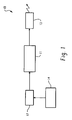
- the exemplary embodiment of the transmitter 10 includes a signal generator 11 that generates a signal having a predetermined longwave frequency. It should be noted that while signal generator 11 generates the "carrier" signal, the actual carrier signal frequency would be determined by the on/off rate of the switch. The nature of this frequency will be discussed later.
- the signal is then "modulated" in an ON/OFF keyed manner in a predetermined sequence and at a predetermined phase angle (e.g.
- the resulting signal is output to an antenna 13, which in turn radiates the signal modulated in an ON/OFF pattern with a predetermined phase angle.
- the antenna 13 can be any antenna suitable for the selected frequency.
- a preferential implementation of the antenna 13 includes a loop antenna, but many others are also possible without departing from the scope of the invention.
- the antenna is designed to propagate the resulting signal using a magnetic field as a primary mode of propagation (as opposed to an electric field, which is intentionally reduced to limit the range of the transmission). While the above implementation shows the signal generator being coupled to the antenna, the carrier generator could be coupled via the switch to the carrier generator, which switch is opened and closed in accordance with the predetermined pattern, thereby generator the desired on/off keyed (OOK) signal.
- OOK on/off keyed
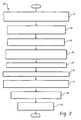
- FIG 2 an exemplary embodiment of a method for communicating an emergency signal is shown in FIG 2 .
- This method 20 communicates the fact that an emergency situation exists.
- the embodiment 20 accomplishes the coding scheme discussed above to transmit this simple fact by varying the repetition rate of a "carrier only" (unmodulated) on/off keyed (OOK) transmission at a specified rate and in a specified pattern (step 21).
- OSK on/off keyed
- the exact specified rate and exact pattern are not important other than that they are known to any potential receivers.
- the scheme that identifies a valid alarm may require that OOK transmissions occur at a repetition rate of 40 Hz for one second, then switch to a repetition rate of 50 Hz for 1 ⁇ 3 second then switch to a repetition rate of 30 Hz for 1 ⁇ 2 second, then nothing ( i.e. , no transmission) for 3 ⁇ 4 second.
- the cycle would then repeat until reset.
- the phase angle of the signal is controlled so that the phase begins at the same point in phase (such as zero or ninety degrees) each time the pulse begins.
- step 22 an electromagnetic wave is generated with a resulting signal in which a primary propagation mode is via magnetic field and which has a reduced electric field.
- the electric field is intentionally reduced to limit the range of the transmission, as well as to avoid interference caused by any application in which electric fields could be problematic.
- the end result is then transmitted as the emergency signal.
- a receiver monitors transmissions at the designated frequency for this pattern of repetition rates.
- a potential receiver monitors the designated frequency for transmissions and attempts to match any received transmissions against the known transmitter repetition rate and pattern.
- FIG 6 depicts an exemplary embodiment 60 of the steps to perform the monitoring step 23 according to another aspect of the present invention.
- the alarm sequence is received using an antenna, such as a loop antenna.
- the specifications of the antenna can be determined once the designated frequency is known as is known in the art.
- the receiving antenna is shielded to prevent interference caused by electric fields, as the desired signals is being propagated via magnetic field as opposed to electric field.
- step 62 complex impedance is tuned to the loop antenna and the transformer of the receiver to develop a resonant circuit.
- a transformer is driven with an output of the antenna in a receiver to provide voltage gain while at the same time reducing the antenna Q by reflecting a real resistance from the secondary to the primary.
- step 64 a band-limited output of the transformer is amplified for further processing.
- step 65 the received alarm sequence is detected in the amplified transformer output to provide an "on/off" keyed representation of the received alarm sequence.
- step 66 the detected representation is converted to a digital representation.
- the steps of envelope detection and conversion to a digital representation can also be performed in the digital domain using an analog-to-digital converter and a signal processor. The result is the same in that a digital sequence is produced from the received analog waveform.
- step 67 the digital representation is processed to determine whether or not the received signals conform to the predetermined sequence that defines the alarm sequence. This processing includes correlating a duration and a period of the digital representation with the predetermined sequence and perhaps averaging to reduce random noise and consequently increase a received signal to noise ratio.
- step 68 the receiver is shielded from electric fields so that the predominant mode being transmitted ( e.g ., via magnetic field propagation) is also the predominant mode being received ( e.g. , magnetic field propagation), thereby providing additional filtering of extraneous signals.
- step 24 when the receiver determines that the pattern is matched, the receiver activates the alarm system.
- This enables a response to be generated and transmitted to the source of the alarm, which can activate a different communications system or which enables a message to be now modulated on the transmitted signal, if desired to provide more information about the nature of the emergency.
- a transmission back to the source can be used to reset the source transmitter (and any intermediate repeaters) to end all transmissions of the original signal.
- a wide variety of responses are possible once an emergency situation is recognized to exist.
- one or more repeaters could identify the alarm sequence, thereby enabling the source to be transmitted to a distant central location over one or more hops, depending on the nature of the specific communication system being established and the environment in which the specific communication system is being located.
- the number of "hops" and their exact characteristics required would be predetermined, and would factor the probability of false alarm against the sequence, so any receiver would activate the alarm system upon receipt. It does not matter if the receiver is located in a home or the local grocery store; if help is required the alarm system is activated.
- each of the one or more repeaters synchronizes to the alarm sequence.
- Another significant advantage of the present invention is simplification of a repeater system. Because the "encoded" alarm message is a repeating cycle of changing pulse repetition rates (or pulse durations, for example), a repeater station need only identify that the pulses it sees are indeed an alarm sequence (as in step 25), then synchronize to the sequence (step 26).
- step 27 the synchronized sequence is then rebroadcast in lockstep with the source.
- the fact that the source may be another repeater station is irrelevant. Since the system is dedicated to the single purpose of summoning emergency assistance, it is permissible, even advantageous, for all repeaters to rebroadcast continually until the entire system is reset (as in step 29) following the emergency response (step 28). The more transmitters involved the higher signal to noise ratio that can be achieved at the receiver.
- the present invention need not consider the repeaters "stepping on each other", as the communication system does not rely on modulation characteristics to communicate the message.
- the alarm protocol preferably includes a programmed maximum dead space, in which no transmissions occur, so that the repeater system can be shut down should the alarm be cancelled, and to permit resynchronization of the repeater system in the event that individual timing variations among the individual repeaters has caused synchronization to be compromised.
- the transmission system can be chosen to reduce or eliminate other potential sources of interference. This would tend to steer an implementation away from the popular unlicensed RF bands.
- the desire to remain wireless requires examination of all regions of the electromagnetic spectrum, from long wavelength IR to RF as the transmission frequency, however, the present invention could be implemented using pressure waves in air (i.e. , sonic waves), for example.
- one exemplary embodiment of the communication system employs a transmission signal having a frequency in the lower frequency ranges, where the system relies on the fact that a poorly matched antenna (from a wavelength perspective) will make the predominate radiation mechanism a magnetic field.
- Radiating predominantly a magnetic field has advantages in limiting the range of the transmission because the magnetic field strength falls off as the cube of the distance from the transmitter. In contrast, electric fields fall off as the square of the distance, so typically transmissions having predominantly electric fields are preferred for long-range transmissions.
- the receiver can be shielded from electric fields using faraday cage techniques, thus reducing the demands on input bandwidth filtering. The point here is to attenuate the electric field without attenuating the magnetic field.
- the receiver 30 includes a shield 37.
- the preferred embodiment of the invention is to operate the transmission in the hundreds of kilohertz frequency range, such as from about 10 kHz to about 1000 kHz. Specific frequencies could be assigned to nearby regions that employ different emergency response systems so that only one communication system would be activated at a time. Operating at these low frequencies improves the "mismatch" between wavelength and the physical length of the antenna, thus favoring the propagation of magnetic fields over electric.
- the source transmitter 10 is then composed of an antenna 13, designed to maximize the generated magnetic field.
- the antenna 13 is driven at the chosen "carrier" frequency (by carrier generator 11), in an on and off pattern that complies with the established pulse repetition rate signature of the alarm indication.
- the sequence generator 14 controls the switch 12 to interrupt the carrier signal output by the signal generator 11 or to turn the signal generator on and off in the desired pattern.
- the transmitter shown in FIG 1 can also be used as a transmitter in a repeater, as discussed below.
- each receiver 30 also is equipped with at least one antenna, such as a multi-turn loop antenna 31 (disposed inside a shield 37), driving preferentially a transformer 32 to provide voltage multiplication as is known in the art.
- a transformer 32 By tuning the complex impedance of the transformer 32 and the antenna 31 with lumped complex impedance 38 (which is a tuning capacitor, which can be in series or in parallel), resonant circuits will result that are reasonably selective in the frequency domain.
- the lumped complex impedance comprises a series capacitor.
- the band-limited output is amplified by amplifier 33 and envelope detected by detector 34 to provide an "on/off' keyed representation of the transmission.
- This signal is then converted by converter 35 to a digital representation for signal processing that will be processed by a microprocessor 36 or other computing device to determine whether or not the received signals conform to the predetermined patterns that describe the alarm signal.
- Signal processing performed by the processor 36 would consist of correlation of the duration and period of received transmissions with the predetermined patterns. Techniques such as averaging (to reduce the contribution of random noise) could be employed to increase the received signal to noise ratio.
- FIG 4 shown therein is an exemplary embodiment 40 of a repeater station according to another aspect of the present invention.
- Repeater stations 40 will of course, retransmit the signal in lockstep with the original transmission should the pulse repetition patterns match those of an alarm.
- lockstep it is not sufficient to simply operate the switches in concert with each other; one must also ensure that each of the carrier generators are synchronized to avoid phase cancellation. This can be accomplished by actually switching the carrier generators on and off so that when each carrier generator is turned “on”, the carrier starts from 0 degrees (or some other predetermined angle) phase shift. This may be simpler than trying to separately synchronize the carrier generators as well as the switch operation.
- the repeater station 40 includes a receiver 30, as described above.
- the output of the receiver 30 (as described in relation to FIG 3 ) in this case would be a decision (e.g. , the alarm signal was received) as well as the pulse sequence, from which a synchronizer 41 would capture a clock signal that would in turn be used to drive the sequence generator in the transmitter 10, as described in relation to FIG 1 .
- Synchronization ensures that each carrier restarts (e.g. , the switch closes) at a predetermined phase shift (in this embodiment, zero degrees) thus all transmitters will operate in-phase with each other. Alternatively, one could simply switch the carrier on and off.
- an alarm receiver (as in FIG 3 ) would, upon validation of the pulse repetition pattern (i.e., a positive decision output by the receiver), perform the steps necessary to activate the emergency signaling to appropriate responders. Any number of events could then occur.
- a response signal would be transmitted so that the original source of the transmission, as well as any and all intermediate repeaters, would be turned off. Then, a subsequent communication channel could be established with the source transmitter in a variety of ways to enable communication of more information to an emergency management system, which would ultimately send the appropriate response.
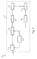
- inductor L 1 (element 72) represents the transmitting antenna.
- Diode D1 (element 74) keeps transistor Q1 (element 75) turned off during the predetermined off periods.
- Transistor Q 1 is a standard N-FET transistor.
- Resistor R1 (element 71) provides bias for the FET 75.
- Capacitor C2 (element 76) is the tuning capacitor so that the circuit is resonant at around 300 kHz.
- the central processing unit (CPU) (e.g. , the device for generating the predetermined pattern of pulses) turns on the FET 75 for a specified period of time (e.g. , 4-20 microseconds). This starts current flowing in the antenna (L1) 72 storing energy in the magnetic field of L1. At a very specific point in time the processor abruptly turns transistor Q1 75 off. This causes the L1-C2-D1 circuit to ring at the circuit's resonant frequency (300 kHz in this embodiment), with the ring starting from ground and the strength of the magnetic field produced by antenna (L1) 72 to oscillate proportional to the current flowing in L1 72. The current in L1 72 and its associated magnetic field strength will ring down based on the Q of the circuit.
- CPU central processing unit
- the circuit behavior is describable in the frequency domain as the convolution of the spectrum of the repeated pulses with the spectrum of the resonant circuit.
- the magnitude of the spectral lines is defined by the spectral envelope of the resonant circuit's "ring", but the location in frequency space of the spectral lines themselves is defined by the repetition rate, not the ring frequency.
- the transmission produces spectral lines spaced in the frequency domain at the desired repetition rate, but whose amplitude follows the spectral shape of the resonant circuit.
- This allows the spectral lines to be located in frequency space using an accurate low frequency source (e.g. , a signal generator of about 32 kHz) and receiver need not rely on the accuracy of the 300 kHz "ring frequency" for tuning.
- the transmitter generates a group of pulses spaced 32 kHz apart, each group being (for example) 12.5 milliseconds long (which in this example provides about 400 pulses). Then, for 12.5 milliseconds, for example, the transmitter sends nothing, and then transmits another 12.5 milliseconds of pulses at 32 kHz, and so on.
- the time domain signal that results is a group of 400 pulses repeating at a 40 Hz rate.
- the receiver then bandpass filters the received signal, and "tunes" the receiver to the expected spectral line (e.g. , in this continuing example, to 288 kHz, which is the ninth harmonic of 32 kHz).
- the receiver down converts the signal and band pass filters the signal at 32 kHz, for example.
- the receiver then down converts the signal again with an intermediate frequency (in this example) of about 32 kHz to isolate the 40 Hz signal, which is then filtered and envelope detected.
- the result is a train of pulses (a digital output) that is at 40 Hz.
- Synchronization of the transmit section of a repeater to the received signal is accomplished by using a conventional edge detector on the 40 Hz digital output to indicate the time at which the received 40 Hz pulse train began and using this information to start the repeater's transmitted pulse train coincidently.
- each repeater in the system is limited to transmitting for a limited period of time, for example 5 seconds, after which it will stop transmission and wait to be "re-activated" by another incoming signal.
- the transmit and stop transmitting times are determined by optimizations that include among others, system range, accuracy of the individual time sources of the repeaters, and the pulse repetition rate.
- this sequence can be further encoded by sending the emergency signal at "40 Hz", for example, for a period of time, then switching the emergency signal to 50 Hz, for example, and so on as described above.
- the transmitter transmits a "predetermined pattern" in a way that permits carrier phase synchronization, which in turn allows the communication system to synchronize multiple transmitters.
- the receiver could include an antenna, a transformer, an amplifier, and analog-to-digital converter and a digital signal processor, or other general-purpose computing device.
- the transmitter and synchronizer could also be implemented digitally. In the case of a digital implementation, care must be taken to accounting for the addition of computer delays.
Landscapes
- Business, Economics & Management (AREA)
- Emergency Management (AREA)
- Physics & Mathematics (AREA)
- General Physics & Mathematics (AREA)
- Engineering & Computer Science (AREA)
- Computer Networks & Wireless Communication (AREA)
- Alarm Systems (AREA)
- Radio Relay Systems (AREA)
- Mobile Radio Communication Systems (AREA)
- Emergency Alarm Devices (AREA)
- Radar Systems Or Details Thereof (AREA)
- Near-Field Transmission Systems (AREA)
Claims (20)
- Procédé (20) de communication d'un signal d'urgence comprenant:l'émission (22) d'une séquence d'alarme comme une séquence tout ou rien répétée prédéterminée d'une fréquence d'onde kilométrique prédéterminée à un angle de phase prédéterminé en utilisant un champ magnétique comme mode primaire de propagation et avec un champ électrique réduit;caractérisé en ce que le procédé comprend de plus les étapes suivantes:identification (25) de la séquence d'alarme par un ou plusieurs répéteurs;synchronisation (26) desdits un ou plusieurs répéteurs sur la séquence d'alarme; etrediffusion (27) de la séquence d'alarme à partir desdits un ou plusieurs répéteurs en synchronisme avec une source de la séquence d'alarme.
- Procédé (20) selon la revendication 1, comprenant de plus:l'activation (24) d'un système de réponse d'alarme à la détermination d'une correspondance de la séquence prédéterminée dans une desdites une ou plusieurs émissions.
- Procédé (20) selon la revendication 1, comprenant de plus:l'émission (28) d'une réponse à la séquence d'alarme à la réception par un système de réponse d'urgence; etl'initialisation (29) d'un ou de plusieurs répéteurs et d'un émetteur source à la réception de la réponse.
- Procédé (20) selon la revendication 1, dans lequel le support d'émission de fréquence prédéterminée inclut une onde acoustique.
- Procédé (20) selon la revendication 1, dans lequel la fréquence prédéterminée inclut un signal à basse fréquence.
- Procédé (20) selon la revendication 1, dans lequel ladite émission (22) comprend de plus:l'émission (53) de la séquence d'alarme de sorte qu'un mode prédominant de la séquence d'alarme soit émis via un champ magnétique.
- Procédé (20) selon la revendication 6, dans lequel ledit contrôle (23) comprend de plus:la protection (68) d'un récepteur de champs électriques.
- Procédé (20) selon la revendication 6, dans lequel le signal à basse fréquence inclut un support d'émission dans un intervalle d'à peu près 10 kilohertz à à peu près 1000 kilohertz.
- Procédé (20) selon la revendication 1, dans lequel ladite émission (21) comprend de plus:l'émission (51) de la séquence d'alarme en utilisant une antenne; etle pilotage (52) de l'antenne avec la fréquence prédéterminée commutée tout ou rien dans la séquence prédéterminée.
- Procédé (20) selon la revendication 9, dans lequel ledit contrôle (23) comprend de plus:la réception (61) de la séquence d'alarme en utilisant une antenne;la syntonisation (63) d'une impédance complexe à l'antenne du récepteur pour développer un circuit résonnant;l'amplification (64) d'une sortie à largeur de bande limitée de l'antenne;la détection (65) d'une enveloppe de la sortie amplifiée pour fournir une représentation "tout ou rien" de la séquence d'alarme reçue;la conversion (66) de la représentation détectée en une représentation numérique; etle traitement (67) de la représentation numérique pour déterminer si les signaux reçus sont ou non conformes à la séquence prédéterminée qui définit la séquence d'alarme.
- Procédé (20) selon la revendication 10, dans lequel ledit traitement (67) inclut:la corrélation d'une durée et d'une période de la représentation numérique avec la séquence prédéterminée.
- Procédé (20) selon la revendication 10, comprenant de plus:la réémission (27) du signal d'alarme en synchronisme avec l'émission originale dans le cas où les motifs de répétition d'impulsion correspondent à ceux d'une séquence d'alarme.
- Procédé (20) selon la revendication 10, comprenant de plus:le pilotage (62) d'un transformateur avec une sortie de l'antenne dans un récepteur pour réfléchir une résistance située dans un enroulement secondaire du transformateur en retour à un enroulement primaire du transformateur pour réduire un Q de l'antenne sans ajouter de résistance réelle et de bruit thermique.
- Procédé (20) selon la revendication 1, dans lequel la séquence d'alarme comprend un premier débit de répétition ayant une première fréquence pour une première période prédéterminée, suivi par un deuxième débit de répétition d'une deuxième fréquence pour une deuxième période prédéterminée, suivi par un troisième débit de répétition d'une troisième fréquence pour une troisième période prédéterminée, n'étant suivi par aucun signal pour une quatrième période prédéterminée.
- Appareil (40) de répétition d'un signal d'urgence comprenant:un récepteur (30) pour écouter sur une fréquence d'onde kilométrique prédéterminée et pour présenter en sortie une séquence numérique à la réception d'une émission de la fréquence d'onde kilométrique prédéterminée, cette séquence numérique représentant une séquence tout ou rien détectée dans la fréquence prédéterminée, ledit récepteur (30) incluant un processeur (36) pour corréler la séquence numérique reçue par rapport à une séquence prédéterminée pour identifier le signal d'urgence;un émetteur (10) incluant:un générateur de signal (11) couplé au processeur (36) pour générer un signal à la fréquence d'onde kilométrique prédéterminée et à un angle de phase prédéterminé lors d'une identification du signal d'urgence par le processeur (36);un commutateur (12) couplé au générateur de signal (11) pour amener une sortie de signal par le générateur de signal à être commutée tout ou rien dans la séquence prédéterminée et l'angle de phase prédéterminé; etune antenne (13) pour rayonner à nouveau le signal prédéterminé dans la séquence prédéterminée comme le signal d'urgence en utilisant un champ magnétique comme mode primaire de propagation et avec un champ électrique réduit; etun synchronisateur (41) couplé au commutateur (11) dans l'émetteur (10) pour synchroniser la séquence prédéterminée générée à la sortie du commutateur (11) avec la séquence numérique reçue et pour synchroniser une phase de la sortie de signal porteur à partir du générateur de signal avec une phase d'un signal porteur reçu par le récepteur (30).
- Appareil (40) selon la revendication 15, dans lequel le récepteur (30) comprend:une antenne blindée (31) pour recevoir une émission sur une porteuse d'onde kilométrique prédéterminée, ladite antenne blindée étant conçue pour générer un courant principalement à partir d'un champ magnétique changeant, et ladite antenne blindée étant conçue pour limiter les champs électriques autour de l'antenne.
- Appareil (40) selon la revendication 15, dans lequel le récepteur inclut:un amplificateur (33) pour amplifier un signal à partir de l'antenne (31); etun convertisseur (35) pour convertir la sortie de signal par l'antenne (31) en la séquence numérique.
- Appareil (40) selon la revendication 17, dans lequel le récepteur comprend de plus:un transformateur (32) couplé à l'antenne (31) et créant un circuit résonnant avec l'antenne (31) à la fréquence prédéterminée; etun blindage (37) au moins disposé autour de l'antenne pour protéger l'antenne de champs électriques.
- Appareil (40) selon la revendication 17, dans lequel le récepteur inclut un détecteur d'enveloppe pour détecter une enveloppe de la sortie de signal à partir de l'antenne, qui est utilisé par le convertisseur pour convertir le signal en la séquence numérique.
- Système de communication (10, 30, 40) pour communiquer un signal d'urgence, comprenant:un émetteur (10) pour émettre un signal d'urgence initial, ledit émetteur (10) incluant:un générateur de signal (11) pour générer un signal à une fréquence d'onde kilométrique prédéterminée et à un angle de phase prédéterminé;un commutateur (12) couplé au générateur de signal pour amener le signal à être interrompu dans une séquence prédéterminée et l'angle de phase prédéterminé; etune antenne (13) pour rayonner le signal interrompu dans la séquence prédéterminée et l'angle de phase prédéterminé comme signal d'urgence à une fréquence d'onde kilométrique en utilisant un champ magnétique comme mode primaire de propagation et avec un champ électrique réduit;un ou plusieurs répéteurs (40), chacun desdits un ou plusieurs répéteurs (40) incluant un appareil pour répéter un signal d'urgence selon la revendication 15; etun récepteur d'alarme (30) pour recevoir le signal d'urgence, ledit récepteur d'alarme (30) servant à écouter sur la fréquence d'onde kilométrique prédéterminée et à présenter en sortie une séquence numérique à la réception d'une émission sur la fréquence d'onde kilométrique prédéterminée, cette séquence numérique représentant une séquence tout ou rien détectée dans la fréquence d'onde kilométrique prédéterminée, ledit récepteur (30) incluant un processeur (36) pour corréler la séquence numérique reçue par rapport à une séquence prédéterminée pour identifier le signal d'urgence.
Applications Claiming Priority (2)
| Application Number | Priority Date | Filing Date | Title |
|---|---|---|---|
| US54582104P | 2004-02-19 | 2004-02-19 | |
| PCT/IB2005/050442 WO2005083649A1 (fr) | 2004-02-19 | 2005-02-02 | Procede et appareil pour communiquer l'existence d'une situation d'urgence sans identifier de façon unique la source de la communication |
Publications (2)
| Publication Number | Publication Date |
|---|---|
| EP1719087A1 EP1719087A1 (fr) | 2006-11-08 |
| EP1719087B1 true EP1719087B1 (fr) | 2008-05-07 |
Family
ID=34910735
Family Applications (1)
| Application Number | Title | Priority Date | Filing Date |
|---|---|---|---|
| EP05702878A Not-in-force EP1719087B1 (fr) | 2004-02-19 | 2005-02-02 | Procede et appareil pour communiquer l'existence d'une situation d'urgence sans identifier de facon unique la source de la communication |
Country Status (6)
| Country | Link |
|---|---|
| US (1) | US7656285B2 (fr) |
| EP (1) | EP1719087B1 (fr) |
| JP (1) | JP4804365B2 (fr) |
| AT (1) | ATE394765T1 (fr) |
| DE (1) | DE602005006532D1 (fr) |
| WO (1) | WO2005083649A1 (fr) |
Families Citing this family (5)
| Publication number | Priority date | Publication date | Assignee | Title |
|---|---|---|---|---|
| NZ581379A (en) * | 2007-05-22 | 2013-02-22 | Telstra Corp Ltd | A repeater system for extending cell coverage by repeating a signal at an alternate frequency |
| CA2700991A1 (fr) * | 2007-09-26 | 2009-04-02 | Radeum, Inc. Dba Freelinc | Systeme et procede de communications en champ proche presentant une securite locale |
| US8482391B2 (en) * | 2008-11-19 | 2013-07-09 | System General Corp. | Wall control interface with phase modulation and detection for power management |
| US8457216B2 (en) * | 2009-12-23 | 2013-06-04 | Alcatel Lucent | Communication via a multimode constellation |
| GB201103822D0 (en) | 2011-03-07 | 2011-04-20 | Isis Innovation | System for providing locality information and associated devices |
Family Cites Families (6)
| Publication number | Priority date | Publication date | Assignee | Title |
|---|---|---|---|---|
| US4251808A (en) | 1979-11-15 | 1981-02-17 | Lichtblau G J | Shielded balanced loop antennas for electronic security systems |
| GB8926505D0 (en) * | 1989-11-23 | 1990-01-10 | Woodbridge Marketing Limited | Method and apparatus for transmitting signals |
| US5926103A (en) | 1994-05-16 | 1999-07-20 | Petite; T. David | Personalized security system |
| US6535545B1 (en) * | 1999-10-15 | 2003-03-18 | Rf Waves Ltd. | RF modem utilizing saw resonator and correlator and communications transceiver constructed therefrom |
| US6501955B1 (en) * | 2000-06-19 | 2002-12-31 | Intel Corporation | RF signal repeater, mobile unit position determination system using the RF signal repeater, and method of communication therefor |
| US7151913B2 (en) * | 2003-06-30 | 2006-12-19 | M/A-Com, Inc. | Electromagnetic wave transmitter, receiver and transceiver systems, methods and articles of manufacture |
-
2005
- 2005-02-02 US US10/598,015 patent/US7656285B2/en active Active
- 2005-02-02 AT AT05702878T patent/ATE394765T1/de not_active IP Right Cessation
- 2005-02-02 EP EP05702878A patent/EP1719087B1/fr not_active Not-in-force
- 2005-02-02 JP JP2006553717A patent/JP4804365B2/ja not_active Expired - Fee Related
- 2005-02-02 DE DE602005006532T patent/DE602005006532D1/de active Active
- 2005-02-02 WO PCT/IB2005/050442 patent/WO2005083649A1/fr active IP Right Grant
Also Published As
| Publication number | Publication date |
|---|---|
| DE602005006532D1 (de) | 2008-06-19 |
| EP1719087A1 (fr) | 2006-11-08 |
| ATE394765T1 (de) | 2008-05-15 |
| US7656285B2 (en) | 2010-02-02 |
| JP2007523555A (ja) | 2007-08-16 |
| JP4804365B2 (ja) | 2011-11-02 |
| US20080151972A1 (en) | 2008-06-26 |
| WO2005083649A1 (fr) | 2005-09-09 |
Similar Documents
| Publication | Publication Date | Title |
|---|---|---|
| JP5438196B2 (ja) | 遠隔通信装置の間の見通し線(los)距離を判定する方法 | |
| EP0293167B1 (fr) | Brouilleur de communication | |
| US6823022B1 (en) | Method for mitigating effects of interference in impulse radio communication | |
| KR101305386B1 (ko) | Rf 기술을 이용한 객체 추적용 감소된 감쇄 방법 및시스템 | |
| EP1719087B1 (fr) | Procede et appareil pour communiquer l'existence d'une situation d'urgence sans identifier de facon unique la source de la communication | |
| KR101744898B1 (ko) | 통합형 금속 검출/전자식 물품 감시 시스템들에서 간섭의 효과를 감소시키기 위한 방법 및 시스템 | |
| JPH11168478A (ja) | 無線位置決定方法及びシステム | |
| US20070105524A1 (en) | Remotely powered wireless microphone | |
| CN104348605B (zh) | 关键应用中使用的用于无线网络的抗干扰技术 | |
| KR20090071567A (ko) | 통신 장치 및 통신 시스템 | |
| AU2019203824A1 (en) | Pulse transmission synchronization | |
| CN102257542A (zh) | 借助数据传输的无线电子商品防盗同步系统和方法 | |
| KR20050110267A (ko) | Tdd 방식의 중계기에서 동기 획득하는 방법 및 장치 | |
| CN100483089C (zh) | 干扰光抑制方法和测量仪器 | |
| JP3368223B2 (ja) | 無線lan装置 | |
| KR100632200B1 (ko) | 통화권 확인 방법 | |
| JP3718440B2 (ja) | 無線機および無線システム | |
| JPH0936816A (ja) | 無線通信装置 | |
| MXPA99010381A (en) | Enhanced identification system | |
| JPH0714089A (ja) | 無線監視装置および無線監視システム | |
| JPH05183478A (ja) | デイジタルセルコール中継システム | |
| JPH0746673A (ja) | 無線監視装置および無線監視システム | |
| KR20010046952A (ko) | 제밍 방지 무선 송수신 방법 | |
| JPH06164543A (ja) | スペクトラム拡散通信装置 |
Legal Events
| Date | Code | Title | Description |
|---|---|---|---|
| PUAI | Public reference made under article 153(3) epc to a published international application that has entered the european phase |
Free format text: ORIGINAL CODE: 0009012 |
|
| 17P | Request for examination filed |
Effective date: 20060919 |
|
| AK | Designated contracting states |
Kind code of ref document: A1 Designated state(s): AT BE BG CH CY CZ DE DK EE ES FI FR GB GR HU IE IS IT LI LT LU MC NL PL PT RO SE SI SK TR |
|
| DAX | Request for extension of the european patent (deleted) | ||
| 17Q | First examination report despatched |
Effective date: 20070507 |
|
| GRAP | Despatch of communication of intention to grant a patent |
Free format text: ORIGINAL CODE: EPIDOSNIGR1 |
|
| GRAS | Grant fee paid |
Free format text: ORIGINAL CODE: EPIDOSNIGR3 |
|
| GRAA | (expected) grant |
Free format text: ORIGINAL CODE: 0009210 |
|
| AK | Designated contracting states |
Kind code of ref document: B1 Designated state(s): AT BE BG CH CY CZ DE DK EE ES FI FR GB GR HU IE IS IT LI LT LU MC NL PL PT RO SE SI SK TR |
|
| REG | Reference to a national code |
Ref country code: GB Ref legal event code: FG4D |
|
| REG | Reference to a national code |
Ref country code: CH Ref legal event code: EP |
|
| REG | Reference to a national code |
Ref country code: IE Ref legal event code: FG4D Free format text: LANGUAGE OF EP DOCUMENT: FRENCH |
|
| REF | Corresponds to: |
Ref document number: 602005006532 Country of ref document: DE Date of ref document: 20080619 Kind code of ref document: P |
|
| PG25 | Lapsed in a contracting state [announced via postgrant information from national office to epo] |
Ref country code: SI Free format text: LAPSE BECAUSE OF FAILURE TO SUBMIT A TRANSLATION OF THE DESCRIPTION OR TO PAY THE FEE WITHIN THE PRESCRIBED TIME-LIMIT Effective date: 20080507 |
|
| PG25 | Lapsed in a contracting state [announced via postgrant information from national office to epo] |
Ref country code: ES Free format text: LAPSE BECAUSE OF FAILURE TO SUBMIT A TRANSLATION OF THE DESCRIPTION OR TO PAY THE FEE WITHIN THE PRESCRIBED TIME-LIMIT Effective date: 20080818 Ref country code: FI Free format text: LAPSE BECAUSE OF FAILURE TO SUBMIT A TRANSLATION OF THE DESCRIPTION OR TO PAY THE FEE WITHIN THE PRESCRIBED TIME-LIMIT Effective date: 20080507 Ref country code: NL Free format text: LAPSE BECAUSE OF FAILURE TO SUBMIT A TRANSLATION OF THE DESCRIPTION OR TO PAY THE FEE WITHIN THE PRESCRIBED TIME-LIMIT Effective date: 20080507 |
|
| NLV1 | Nl: lapsed or annulled due to failure to fulfill the requirements of art. 29p and 29m of the patents act | ||
| PG25 | Lapsed in a contracting state [announced via postgrant information from national office to epo] |
Ref country code: PL Free format text: LAPSE BECAUSE OF FAILURE TO SUBMIT A TRANSLATION OF THE DESCRIPTION OR TO PAY THE FEE WITHIN THE PRESCRIBED TIME-LIMIT Effective date: 20080507 Ref country code: AT Free format text: LAPSE BECAUSE OF FAILURE TO SUBMIT A TRANSLATION OF THE DESCRIPTION OR TO PAY THE FEE WITHIN THE PRESCRIBED TIME-LIMIT Effective date: 20080507 |
|
| PG25 | Lapsed in a contracting state [announced via postgrant information from national office to epo] |
Ref country code: IS Free format text: LAPSE BECAUSE OF FAILURE TO SUBMIT A TRANSLATION OF THE DESCRIPTION OR TO PAY THE FEE WITHIN THE PRESCRIBED TIME-LIMIT Effective date: 20080907 |
|
| PG25 | Lapsed in a contracting state [announced via postgrant information from national office to epo] |
Ref country code: CZ Free format text: LAPSE BECAUSE OF FAILURE TO SUBMIT A TRANSLATION OF THE DESCRIPTION OR TO PAY THE FEE WITHIN THE PRESCRIBED TIME-LIMIT Effective date: 20080507 Ref country code: DK Free format text: LAPSE BECAUSE OF FAILURE TO SUBMIT A TRANSLATION OF THE DESCRIPTION OR TO PAY THE FEE WITHIN THE PRESCRIBED TIME-LIMIT Effective date: 20080507 Ref country code: SE Free format text: LAPSE BECAUSE OF FAILURE TO SUBMIT A TRANSLATION OF THE DESCRIPTION OR TO PAY THE FEE WITHIN THE PRESCRIBED TIME-LIMIT Effective date: 20080807 Ref country code: LT Free format text: LAPSE BECAUSE OF FAILURE TO SUBMIT A TRANSLATION OF THE DESCRIPTION OR TO PAY THE FEE WITHIN THE PRESCRIBED TIME-LIMIT Effective date: 20080507 |
|
| PG25 | Lapsed in a contracting state [announced via postgrant information from national office to epo] |
Ref country code: SK Free format text: LAPSE BECAUSE OF FAILURE TO SUBMIT A TRANSLATION OF THE DESCRIPTION OR TO PAY THE FEE WITHIN THE PRESCRIBED TIME-LIMIT Effective date: 20080507 Ref country code: RO Free format text: LAPSE BECAUSE OF FAILURE TO SUBMIT A TRANSLATION OF THE DESCRIPTION OR TO PAY THE FEE WITHIN THE PRESCRIBED TIME-LIMIT Effective date: 20080507 Ref country code: PT Free format text: LAPSE BECAUSE OF FAILURE TO SUBMIT A TRANSLATION OF THE DESCRIPTION OR TO PAY THE FEE WITHIN THE PRESCRIBED TIME-LIMIT Effective date: 20081007 Ref country code: BE Free format text: LAPSE BECAUSE OF FAILURE TO SUBMIT A TRANSLATION OF THE DESCRIPTION OR TO PAY THE FEE WITHIN THE PRESCRIBED TIME-LIMIT Effective date: 20080507 |
|
| PLBE | No opposition filed within time limit |
Free format text: ORIGINAL CODE: 0009261 |
|
| STAA | Information on the status of an ep patent application or granted ep patent |
Free format text: STATUS: NO OPPOSITION FILED WITHIN TIME LIMIT |
|
| 26N | No opposition filed |
Effective date: 20090210 |
|
| PG25 | Lapsed in a contracting state [announced via postgrant information from national office to epo] |
Ref country code: EE Free format text: LAPSE BECAUSE OF FAILURE TO SUBMIT A TRANSLATION OF THE DESCRIPTION OR TO PAY THE FEE WITHIN THE PRESCRIBED TIME-LIMIT Effective date: 20080507 Ref country code: BG Free format text: LAPSE BECAUSE OF FAILURE TO SUBMIT A TRANSLATION OF THE DESCRIPTION OR TO PAY THE FEE WITHIN THE PRESCRIBED TIME-LIMIT Effective date: 20080807 |
|
| PG25 | Lapsed in a contracting state [announced via postgrant information from national office to epo] |
Ref country code: IT Free format text: LAPSE BECAUSE OF FAILURE TO SUBMIT A TRANSLATION OF THE DESCRIPTION OR TO PAY THE FEE WITHIN THE PRESCRIBED TIME-LIMIT Effective date: 20080507 |
|
| PG25 | Lapsed in a contracting state [announced via postgrant information from national office to epo] |
Ref country code: MC Free format text: LAPSE BECAUSE OF NON-PAYMENT OF DUE FEES Effective date: 20090228 |
|
| REG | Reference to a national code |
Ref country code: CH Ref legal event code: PL |
|
| PG25 | Lapsed in a contracting state [announced via postgrant information from national office to epo] |
Ref country code: LI Free format text: LAPSE BECAUSE OF NON-PAYMENT OF DUE FEES Effective date: 20090228 Ref country code: CH Free format text: LAPSE BECAUSE OF NON-PAYMENT OF DUE FEES Effective date: 20090228 |
|
| PG25 | Lapsed in a contracting state [announced via postgrant information from national office to epo] |
Ref country code: IE Free format text: LAPSE BECAUSE OF NON-PAYMENT OF DUE FEES Effective date: 20090202 |
|
| PG25 | Lapsed in a contracting state [announced via postgrant information from national office to epo] |
Ref country code: GR Free format text: LAPSE BECAUSE OF FAILURE TO SUBMIT A TRANSLATION OF THE DESCRIPTION OR TO PAY THE FEE WITHIN THE PRESCRIBED TIME-LIMIT Effective date: 20080808 |
|
| PG25 | Lapsed in a contracting state [announced via postgrant information from national office to epo] |
Ref country code: LU Free format text: LAPSE BECAUSE OF NON-PAYMENT OF DUE FEES Effective date: 20090202 |
|
| PG25 | Lapsed in a contracting state [announced via postgrant information from national office to epo] |
Ref country code: HU Free format text: LAPSE BECAUSE OF FAILURE TO SUBMIT A TRANSLATION OF THE DESCRIPTION OR TO PAY THE FEE WITHIN THE PRESCRIBED TIME-LIMIT Effective date: 20081108 |
|
| PG25 | Lapsed in a contracting state [announced via postgrant information from national office to epo] |
Ref country code: TR Free format text: LAPSE BECAUSE OF FAILURE TO SUBMIT A TRANSLATION OF THE DESCRIPTION OR TO PAY THE FEE WITHIN THE PRESCRIBED TIME-LIMIT Effective date: 20080507 |
|
| PG25 | Lapsed in a contracting state [announced via postgrant information from national office to epo] |
Ref country code: CY Free format text: LAPSE BECAUSE OF FAILURE TO SUBMIT A TRANSLATION OF THE DESCRIPTION OR TO PAY THE FEE WITHIN THE PRESCRIBED TIME-LIMIT Effective date: 20080507 |
|
| REG | Reference to a national code |
Ref country code: DE Ref legal event code: R082 Ref document number: 602005006532 Country of ref document: DE Representative=s name: MEISSNER, BOLTE & PARTNER GBR, DE |
|
| REG | Reference to a national code |
Ref country code: DE Ref legal event code: R081 Ref document number: 602005006532 Country of ref document: DE Owner name: KONINKLIJKE PHILIPS N.V., NL Free format text: FORMER OWNER: KONINKLIJKE PHILIPS ELECTRONICS N.V., EINDHOVEN, NL Effective date: 20140328 Ref country code: DE Ref legal event code: R082 Ref document number: 602005006532 Country of ref document: DE Representative=s name: MEISSNER, BOLTE & PARTNER GBR, DE Effective date: 20140328 Ref country code: DE Ref legal event code: R082 Ref document number: 602005006532 Country of ref document: DE Representative=s name: MEISSNER BOLTE PATENTANWAELTE RECHTSANWAELTE P, DE Effective date: 20140328 |
|
| REG | Reference to a national code |
Ref country code: FR Ref legal event code: CA Effective date: 20141126 Ref country code: FR Ref legal event code: CD Owner name: KONINKLIJKE PHILIPS N.V., NL Effective date: 20141126 |
|
| REG | Reference to a national code |
Ref country code: FR Ref legal event code: PLFP Year of fee payment: 12 |
|
| REG | Reference to a national code |
Ref country code: FR Ref legal event code: PLFP Year of fee payment: 13 |
|
| REG | Reference to a national code |
Ref country code: FR Ref legal event code: PLFP Year of fee payment: 14 |
|
| REG | Reference to a national code |
Ref country code: DE Ref legal event code: R082 Ref document number: 602005006532 Country of ref document: DE Representative=s name: HL KEMPNER PATENTANWALT, RECHTSANWALT, SOLICIT, DE Ref country code: DE Ref legal event code: R081 Ref document number: 602005006532 Country of ref document: DE Owner name: LIFELINE SYSTEMS COMPANY, FRAMINGHAM, US Free format text: FORMER OWNER: KONINKLIJKE PHILIPS N.V., EINDHOVEN, NL Ref country code: DE Ref legal event code: R082 Ref document number: 602005006532 Country of ref document: DE |
|
| REG | Reference to a national code |
Ref country code: DE Ref legal event code: R082 Ref document number: 602005006532 Country of ref document: DE Representative=s name: HL KEMPNER PATENTANWALT, RECHTSANWALT, SOLICIT, DE |
|
| REG | Reference to a national code |
Ref country code: GB Ref legal event code: 732E Free format text: REGISTERED BETWEEN 20211202 AND 20211209 |
|
| PGFP | Annual fee paid to national office [announced via postgrant information from national office to epo] |
Ref country code: FR Payment date: 20211217 Year of fee payment: 18 Ref country code: GB Payment date: 20211209 Year of fee payment: 18 |
|
| PGFP | Annual fee paid to national office [announced via postgrant information from national office to epo] |
Ref country code: DE Payment date: 20211207 Year of fee payment: 18 |
|
| REG | Reference to a national code |
Ref country code: DE Ref legal event code: R119 Ref document number: 602005006532 Country of ref document: DE |
|
| GBPC | Gb: european patent ceased through non-payment of renewal fee |
Effective date: 20230202 |
|
| PG25 | Lapsed in a contracting state [announced via postgrant information from national office to epo] |
Ref country code: GB Free format text: LAPSE BECAUSE OF NON-PAYMENT OF DUE FEES Effective date: 20230202 |
|
| PG25 | Lapsed in a contracting state [announced via postgrant information from national office to epo] |
Ref country code: GB Free format text: LAPSE BECAUSE OF NON-PAYMENT OF DUE FEES Effective date: 20230202 Ref country code: FR Free format text: LAPSE BECAUSE OF NON-PAYMENT OF DUE FEES Effective date: 20230228 Ref country code: DE Free format text: LAPSE BECAUSE OF NON-PAYMENT OF DUE FEES Effective date: 20230901 |