EP1718402B1 - Mikromischer - Google Patents
Mikromischer Download PDFInfo
- Publication number
- EP1718402B1 EP1718402B1 EP05707247A EP05707247A EP1718402B1 EP 1718402 B1 EP1718402 B1 EP 1718402B1 EP 05707247 A EP05707247 A EP 05707247A EP 05707247 A EP05707247 A EP 05707247A EP 1718402 B1 EP1718402 B1 EP 1718402B1
- Authority
- EP
- European Patent Office
- Prior art keywords
- mixing
- micromixer
- flow
- sub
- reaction zone
- Prior art date
- Legal status (The legal status is an assumption and is not a legal conclusion. Google has not performed a legal analysis and makes no representation as to the accuracy of the status listed.)
- Active
Links
- 238000002156 mixing Methods 0.000 claims abstract description 77
- 238000006243 chemical reaction Methods 0.000 claims abstract description 60
- 239000012530 fluid Substances 0.000 claims abstract description 30
- 238000001556 precipitation Methods 0.000 claims abstract description 15
- 239000000725 suspension Substances 0.000 claims abstract description 8
- 239000002245 particle Substances 0.000 claims description 21
- 238000000034 method Methods 0.000 claims description 17
- 238000004140 cleaning Methods 0.000 claims description 11
- 230000008569 process Effects 0.000 claims description 11
- 238000002425 crystallisation Methods 0.000 claims description 10
- 230000008025 crystallization Effects 0.000 claims description 10
- 239000012528 membrane Substances 0.000 claims description 9
- 230000004888 barrier function Effects 0.000 claims description 8
- 239000002105 nanoparticle Substances 0.000 claims description 8
- 239000002244 precipitate Substances 0.000 claims description 5
- 239000000126 substance Substances 0.000 claims description 5
- 238000002360 preparation method Methods 0.000 claims description 4
- OKTJSMMVPCPJKN-UHFFFAOYSA-N Carbon Chemical compound [C] OKTJSMMVPCPJKN-UHFFFAOYSA-N 0.000 claims description 2
- 239000002041 carbon nanotube Substances 0.000 claims description 2
- 229910021393 carbon nanotube Inorganic materials 0.000 claims description 2
- 230000004044 response Effects 0.000 claims description 2
- 238000010992 reflux Methods 0.000 claims 7
- XMWRBQBLMFGWIX-UHFFFAOYSA-N C60 fullerene Chemical class C12=C3C(C4=C56)=C7C8=C5C5=C9C%10=C6C6=C4C1=C1C4=C6C6=C%10C%10=C9C9=C%11C5=C8C5=C8C7=C3C3=C7C2=C1C1=C2C4=C6C4=C%10C6=C9C9=C%11C5=C5C8=C3C3=C7C1=C1C2=C4C6=C2C9=C5C3=C12 XMWRBQBLMFGWIX-UHFFFAOYSA-N 0.000 claims 1
- 229910003472 fullerene Inorganic materials 0.000 claims 1
- 239000010409 thin film Substances 0.000 claims 1
- 230000036961 partial effect Effects 0.000 abstract description 88
- 230000002265 prevention Effects 0.000 abstract 1
- 239000000047 product Substances 0.000 description 16
- 125000006850 spacer group Chemical group 0.000 description 10
- 239000007789 gas Substances 0.000 description 7
- 238000010899 nucleation Methods 0.000 description 7
- 230000006911 nucleation Effects 0.000 description 7
- 239000007787 solid Substances 0.000 description 7
- 238000004519 manufacturing process Methods 0.000 description 6
- 239000000463 material Substances 0.000 description 6
- 239000000203 mixture Substances 0.000 description 6
- 230000008901 benefit Effects 0.000 description 5
- 238000013461 design Methods 0.000 description 5
- 239000007788 liquid Substances 0.000 description 5
- 230000000694 effects Effects 0.000 description 4
- 230000015572 biosynthetic process Effects 0.000 description 3
- 239000007795 chemical reaction product Substances 0.000 description 3
- 238000005485 electric heating Methods 0.000 description 3
- 238000002347 injection Methods 0.000 description 3
- 239000007924 injection Substances 0.000 description 3
- 238000007789 sealing Methods 0.000 description 3
- 238000000926 separation method Methods 0.000 description 3
- MCMNRKCIXSYSNV-UHFFFAOYSA-N Zirconium dioxide Chemical compound O=[Zr]=O MCMNRKCIXSYSNV-UHFFFAOYSA-N 0.000 description 2
- IISBACLAFKSPIT-UHFFFAOYSA-N bisphenol A Chemical compound C=1C=C(O)C=CC=1C(C)(C)C1=CC=C(O)C=C1 IISBACLAFKSPIT-UHFFFAOYSA-N 0.000 description 2
- 238000010276 construction Methods 0.000 description 2
- 239000013078 crystal Substances 0.000 description 2
- 230000003670 easy-to-clean Effects 0.000 description 2
- 239000000839 emulsion Substances 0.000 description 2
- 230000006872 improvement Effects 0.000 description 2
- 238000009413 insulation Methods 0.000 description 2
- 238000004886 process control Methods 0.000 description 2
- 239000002904 solvent Substances 0.000 description 2
- 238000012546 transfer Methods 0.000 description 2
- QGZKDVFQNNGYKY-UHFFFAOYSA-N Ammonia Chemical compound N QGZKDVFQNNGYKY-UHFFFAOYSA-N 0.000 description 1
- 229910052581 Si3N4 Inorganic materials 0.000 description 1
- RTAQQCXQSZGOHL-UHFFFAOYSA-N Titanium Chemical compound [Ti] RTAQQCXQSZGOHL-UHFFFAOYSA-N 0.000 description 1
- 238000010521 absorption reaction Methods 0.000 description 1
- 230000001133 acceleration Effects 0.000 description 1
- 239000002253 acid Substances 0.000 description 1
- 239000004480 active ingredient Substances 0.000 description 1
- 239000013543 active substance Substances 0.000 description 1
- 230000001154 acute effect Effects 0.000 description 1
- 230000002411 adverse Effects 0.000 description 1
- 229910045601 alloy Inorganic materials 0.000 description 1
- 239000000956 alloy Substances 0.000 description 1
- PNEYBMLMFCGWSK-UHFFFAOYSA-N aluminium oxide Inorganic materials [O-2].[O-2].[O-2].[Al+3].[Al+3] PNEYBMLMFCGWSK-UHFFFAOYSA-N 0.000 description 1
- 238000000149 argon plasma sintering Methods 0.000 description 1
- 230000009286 beneficial effect Effects 0.000 description 1
- 230000002051 biphasic effect Effects 0.000 description 1
- 230000001914 calming effect Effects 0.000 description 1
- 230000015556 catabolic process Effects 0.000 description 1
- 230000003197 catalytic effect Effects 0.000 description 1
- 229910010293 ceramic material Inorganic materials 0.000 description 1
- 238000001311 chemical methods and process Methods 0.000 description 1
- 239000012295 chemical reaction liquid Substances 0.000 description 1
- 230000003750 conditioning effect Effects 0.000 description 1
- 238000001816 cooling Methods 0.000 description 1
- PMHQVHHXPFUNSP-UHFFFAOYSA-M copper(1+);methylsulfanylmethane;bromide Chemical compound Br[Cu].CSC PMHQVHHXPFUNSP-UHFFFAOYSA-M 0.000 description 1
- 230000001419 dependent effect Effects 0.000 description 1
- 238000009792 diffusion process Methods 0.000 description 1
- 238000010790 dilution Methods 0.000 description 1
- 239000012895 dilution Substances 0.000 description 1
- 239000003814 drug Substances 0.000 description 1
- 229940079593 drug Drugs 0.000 description 1
- 238000009760 electrical discharge machining Methods 0.000 description 1
- 238000005516 engineering process Methods 0.000 description 1
- 230000005284 excitation Effects 0.000 description 1
- 230000007717 exclusion Effects 0.000 description 1
- 230000002349 favourable effect Effects 0.000 description 1
- 238000001595 flow curve Methods 0.000 description 1
- 238000000227 grinding Methods 0.000 description 1
- 229930195733 hydrocarbon Natural products 0.000 description 1
- 150000002430 hydrocarbons Chemical class 0.000 description 1
- 230000001771 impaired effect Effects 0.000 description 1
- 238000011065 in-situ storage Methods 0.000 description 1
- 239000003112 inhibitor Substances 0.000 description 1
- 150000002484 inorganic compounds Chemical class 0.000 description 1
- 229910010272 inorganic material Inorganic materials 0.000 description 1
- 239000012212 insulator Substances 0.000 description 1
- 230000010354 integration Effects 0.000 description 1
- 230000001788 irregular Effects 0.000 description 1
- 238000003475 lamination Methods 0.000 description 1
- 238000003754 machining Methods 0.000 description 1
- 238000005259 measurement Methods 0.000 description 1
- 238000010327 methods by industry Methods 0.000 description 1
- 239000003595 mist Substances 0.000 description 1
- 239000000178 monomer Substances 0.000 description 1
- 238000003541 multi-stage reaction Methods 0.000 description 1
- 239000006070 nanosuspension Substances 0.000 description 1
- 238000006386 neutralization reaction Methods 0.000 description 1
- 230000003287 optical effect Effects 0.000 description 1
- 150000002894 organic compounds Chemical class 0.000 description 1
- 239000012860 organic pigment Substances 0.000 description 1
- 230000000737 periodic effect Effects 0.000 description 1
- 230000000704 physical effect Effects 0.000 description 1
- 229920000642 polymer Polymers 0.000 description 1
- 238000006116 polymerization reaction Methods 0.000 description 1
- 239000004810 polytetrafluoroethylene Substances 0.000 description 1
- 229920001343 polytetrafluoroethylene Polymers 0.000 description 1
- 238000010944 pre-mature reactiony Methods 0.000 description 1
- 230000036316 preload Effects 0.000 description 1
- 238000010903 primary nucleation Methods 0.000 description 1
- 238000012545 processing Methods 0.000 description 1
- 230000005855 radiation Effects 0.000 description 1
- 239000011541 reaction mixture Substances 0.000 description 1
- 230000002829 reductive effect Effects 0.000 description 1
- 230000011218 segmentation Effects 0.000 description 1
- HBMJWWWQQXIZIP-UHFFFAOYSA-N silicon carbide Chemical compound [Si+]#[C-] HBMJWWWQQXIZIP-UHFFFAOYSA-N 0.000 description 1
- 229910010271 silicon carbide Inorganic materials 0.000 description 1
- HQVNEWCFYHHQES-UHFFFAOYSA-N silicon nitride Chemical compound N12[Si]34N5[Si]62N3[Si]51N64 HQVNEWCFYHHQES-UHFFFAOYSA-N 0.000 description 1
- 239000012265 solid product Substances 0.000 description 1
- 239000000243 solution Substances 0.000 description 1
- 239000003381 stabilizer Substances 0.000 description 1
- 229910001220 stainless steel Inorganic materials 0.000 description 1
- 230000003068 static effect Effects 0.000 description 1
- 238000003756 stirring Methods 0.000 description 1
- 238000003786 synthesis reaction Methods 0.000 description 1
- 229910052715 tantalum Inorganic materials 0.000 description 1
- GUVRBAGPIYLISA-UHFFFAOYSA-N tantalum atom Chemical compound [Ta] GUVRBAGPIYLISA-UHFFFAOYSA-N 0.000 description 1
- 229910052719 titanium Inorganic materials 0.000 description 1
- 239000010936 titanium Substances 0.000 description 1
- 230000001960 triggered effect Effects 0.000 description 1
Images


Classifications
-
- B—PERFORMING OPERATIONS; TRANSPORTING
- B01—PHYSICAL OR CHEMICAL PROCESSES OR APPARATUS IN GENERAL
- B01F—MIXING, e.g. DISSOLVING, EMULSIFYING OR DISPERSING
- B01F25/00—Flow mixers; Mixers for falling materials, e.g. solid particles
-
- B—PERFORMING OPERATIONS; TRANSPORTING
- B82—NANOTECHNOLOGY
- B82Y—SPECIFIC USES OR APPLICATIONS OF NANOSTRUCTURES; MEASUREMENT OR ANALYSIS OF NANOSTRUCTURES; MANUFACTURE OR TREATMENT OF NANOSTRUCTURES
- B82Y30/00—Nanotechnology for materials or surface science, e.g. nanocomposites
-
- B—PERFORMING OPERATIONS; TRANSPORTING
- B01—PHYSICAL OR CHEMICAL PROCESSES OR APPARATUS IN GENERAL
- B01F—MIXING, e.g. DISSOLVING, EMULSIFYING OR DISPERSING
- B01F25/00—Flow mixers; Mixers for falling materials, e.g. solid particles
- B01F25/105—Mixing heads, i.e. compact mixing units or modules, using mixing valves for feeding and mixing at least two components
-
- B—PERFORMING OPERATIONS; TRANSPORTING
- B01—PHYSICAL OR CHEMICAL PROCESSES OR APPARATUS IN GENERAL
- B01F—MIXING, e.g. DISSOLVING, EMULSIFYING OR DISPERSING
- B01F35/00—Accessories for mixers; Auxiliary operations or auxiliary devices; Parts or details of general application
-
- B—PERFORMING OPERATIONS; TRANSPORTING
- B01—PHYSICAL OR CHEMICAL PROCESSES OR APPARATUS IN GENERAL
- B01F—MIXING, e.g. DISSOLVING, EMULSIFYING OR DISPERSING
- B01F35/00—Accessories for mixers; Auxiliary operations or auxiliary devices; Parts or details of general application
- B01F35/10—Maintenance of mixers
- B01F35/145—Washing or cleaning mixers not provided for in other groups in this subclass; Inhibiting build-up of material on machine parts using other means
-
- F—MECHANICAL ENGINEERING; LIGHTING; HEATING; WEAPONS; BLASTING
- F16—ENGINEERING ELEMENTS AND UNITS; GENERAL MEASURES FOR PRODUCING AND MAINTAINING EFFECTIVE FUNCTIONING OF MACHINES OR INSTALLATIONS; THERMAL INSULATION IN GENERAL
- F16K—VALVES; TAPS; COCKS; ACTUATING-FLOATS; DEVICES FOR VENTING OR AERATING
- F16K15/00—Check valves
- F16K15/02—Check valves with guided rigid valve members
- F16K15/025—Check valves with guided rigid valve members the valve being loaded by a spring
- F16K15/026—Check valves with guided rigid valve members the valve being loaded by a spring the valve member being a movable body around which the medium flows when the valve is open
-
- F—MECHANICAL ENGINEERING; LIGHTING; HEATING; WEAPONS; BLASTING
- F16—ENGINEERING ELEMENTS AND UNITS; GENERAL MEASURES FOR PRODUCING AND MAINTAINING EFFECTIVE FUNCTIONING OF MACHINES OR INSTALLATIONS; THERMAL INSULATION IN GENERAL
- F16K—VALVES; TAPS; COCKS; ACTUATING-FLOATS; DEVICES FOR VENTING OR AERATING
- F16K15/00—Check valves
- F16K15/02—Check valves with guided rigid valve members
- F16K15/06—Check valves with guided rigid valve members with guided stems
- F16K15/063—Check valves with guided rigid valve members with guided stems the valve being loaded by a spring
-
- F—MECHANICAL ENGINEERING; LIGHTING; HEATING; WEAPONS; BLASTING
- F16—ENGINEERING ELEMENTS AND UNITS; GENERAL MEASURES FOR PRODUCING AND MAINTAINING EFFECTIVE FUNCTIONING OF MACHINES OR INSTALLATIONS; THERMAL INSULATION IN GENERAL
- F16K—VALVES; TAPS; COCKS; ACTUATING-FLOATS; DEVICES FOR VENTING OR AERATING
- F16K15/00—Check valves
- F16K15/14—Check valves with flexible valve members
- F16K15/144—Check valves with flexible valve members the closure elements being fixed along all or a part of their periphery
- F16K15/145—Check valves with flexible valve members the closure elements being fixed along all or a part of their periphery the closure elements being shaped as a solids of revolution, e.g. cylindrical or conical
-
- F—MECHANICAL ENGINEERING; LIGHTING; HEATING; WEAPONS; BLASTING
- F16—ENGINEERING ELEMENTS AND UNITS; GENERAL MEASURES FOR PRODUCING AND MAINTAINING EFFECTIVE FUNCTIONING OF MACHINES OR INSTALLATIONS; THERMAL INSULATION IN GENERAL
- F16K—VALVES; TAPS; COCKS; ACTUATING-FLOATS; DEVICES FOR VENTING OR AERATING
- F16K17/00—Safety valves; Equalising valves, e.g. pressure relief valves
- F16K17/02—Safety valves; Equalising valves, e.g. pressure relief valves opening on surplus pressure on one side; closing on insufficient pressure on one side
- F16K17/04—Safety valves; Equalising valves, e.g. pressure relief valves opening on surplus pressure on one side; closing on insufficient pressure on one side spring-loaded
- F16K17/06—Safety valves; Equalising valves, e.g. pressure relief valves opening on surplus pressure on one side; closing on insufficient pressure on one side spring-loaded with special arrangements for adjusting the opening pressure
-
- B—PERFORMING OPERATIONS; TRANSPORTING
- B01—PHYSICAL OR CHEMICAL PROCESSES OR APPARATUS IN GENERAL
- B01F—MIXING, e.g. DISSOLVING, EMULSIFYING OR DISPERSING
- B01F33/00—Other mixers; Mixing plants; Combinations of mixers
- B01F33/30—Micromixers
-
- B—PERFORMING OPERATIONS; TRANSPORTING
- B82—NANOTECHNOLOGY
- B82Y—SPECIFIC USES OR APPLICATIONS OF NANOSTRUCTURES; MEASUREMENT OR ANALYSIS OF NANOSTRUCTURES; MANUFACTURE OR TREATMENT OF NANOSTRUCTURES
- B82Y40/00—Manufacture or treatment of nanostructures
Definitions
- the invention relates to a micromixer for mixing at least two fluids which react to form precipitates or suspensions.
- microstructured components in fluid mixing apparatus provides product quality advantages as well as reduces mixing time and size of required equipment compared to conventional designs.
- An essential feature of microstructured. Components are the small dimensions of the fluid channels, which are typically located in the range between 10 and 5,000 microns. For this reason, for example, with multilamination mixers fine fluid fins can be generated, between which due to their small thickness, a rapid mass transfer can occur by diffusion.
- the small dimensions of the flow-through cross sections also require special measures to protect them against deposits and blockages during operation. For example, particulate filters are used in the inflow of such components, the selection of the separation limit being based on the dimensions of the microstructure.
- a premature reaction of the fluids is thereby avoided and shifted to a non-critical region of a mixer device.
- Another way to prevent the deposits and blockages in the microstructures is in the DE 202 18 972 U1 described.
- the components of a static lamination micromixer are designed to be easily accessible and easy to clean.
- suspensions in microstructured components can then still be handled to the exclusion of blockages, if the dimensions of the microstructures are significantly larger than the occurring maximum particle dimensions.
- organic pigments are recommended for dimensioning the microstructured regions within a reactor such that the smallest clear width of the microstructures advantageously about ten times larger than the diameter of the largest particles.
- wall covering which has formed, for example, from solids participating in the chemical synthesis or the physical process, is almost completely removed.
- special design measures and special types of process control are known which prevent the formation of wall coverings and the clogging of the microstructured components.
- the separation fluid may adversely affect the reaction by causing dilution of a single-phase mixture and reducing the supersaturation for the precipitation reaction and hence the yield of the reaction.
- such separation fluid must then be separated from the product stream.
- inhalable drugs which consists of a micromixer, a Segmenter and a subsequent dwell.
- a micromixer for example, two liquid components are mixed, which are divided into individual units in the segmenter, wherein the individual units are separated by a different phase.
- This biphasic system is then heated in a residence zone to initiate the reaction leading to the formation of solids.
- the segmentation of the reacting phase prevents the formation of larger agglomerates.
- the point of collision between two jets of fluids is some distance from the nozzles, which are used to angle the fluids to each other, so that blockage of the jets can be precluded.
- the WO 01/62374 A2 describes a process for the preparation of nanosuspensions. The fluids enter after mixing in a mixing chamber in a nozzle, which they leave via an outlet channel. The mixing is achieved by turbulence, so that deposits and blockages of the microstructures is prevented in this way.
- document DE-A-197 07 165 discloses a mixer according to the preamble of claim 1.
- the solutions used hitherto against deposits and blockages of the microstructures consist in the following measures:
- the components of the microstructures are designed so that they are easily accessible and easy to clean, too If they are constructed significantly larger than the particles, in addition dwell lines and additional channels for auxiliary flows can be provided.
- the methods for preventing deposits and blockages on microreactors provide for process-accompanying cleaning, suitable flow guides, mixing away from the supply channels or generation of turbulence. All measures have in common that they affect the efficiency of the microreactors or signify great additional effort.
- the object of the present invention is to provide a micromixer for mixing at least two fluids, which ensures fast and efficient mixing of the fluids and at the same time good resistance to undesired ones. Has deposits and blockages in the microstructures.
- the object is surprisingly achieved by the micromixer according to the invention.
- the invention therefore provides micromixers for mixing at least two fluids which react to form precipitates or suspensions with the features of claim 1.
- the micromixer according to the invention for mixing at least two fluids reacting to form precipitates or suspensions has a first channel for the supply of a first partial flow and a second channel for the supply of a second partial flow. Both channels preferably open into narrow inlet gaps in a mixing and reaction zone and leave them via an outlet channel. Between the mixing and reaction zone and at least one channel for the supply of a partial flow, a backflow preventer is arranged. As an advantage of the micromixer according to the invention, it turns out that no backflows occur in the mixing and reaction zone. As a result, the associated precipitation reactions in the inlet areas of the mixing and reaction zone are avoided. In the mixing and reaction zone, the primary nucleation succeeds for the later precipitations and crystallization processes.
- Uniform growth of nucleated seeds into uniform particle size requires that the mixing and reaction zone complete a uniform flow field at low velocities. This is realized with advantage by an outlet channel with a smooth and widening geometry.
- the backflow barrier of the micromixer is preferably designed as a check valve or as a membrane arrangement.
- the bias of the spring of the check valve can be adjusted by mechanical means.
- the spring preload and / or the spring constant and thus the set pressure or the opening behavior of the check valve during operation of the mixer can be adjusted from the outside.
- the use of an electric, pneumatic, hydraulic or electromagnetic drive proves to be advantageous for the check valve.
- the width of at least one of the inlet column and / or the characteristic dimension of the mixing and reaction zone during operation of the mixer can be adjusted continuously or stepwise.
- the adjustment of these sizes can be achieved by mechanical, pneumatic, hydraulic, piezoelectric, electrostatic or electromagnetic drive.
- these variables can also be incorporated as manipulated variables in a control loop.
- the width of at least one of the inlet gaps and / or the characteristic dimension of the mixing and reaction zone preference is given to chemical or physical properties of the mixing or reaction product, in particular those which are distinguished by a determine fast online measurement, such as Temperature, color, light scattering or absorption behavior, pH or electrical conductivity, used.
- the inlet gaps for the various partial flows can be linear - then preferably parallel or radial, or curved - then preferably annularly concentric or axially in sequence - be arranged.
- Linearly arranged entrance gaps are particularly advantageously suitable for micromixers according to the invention for high volume flows; eg to realize above some 100 L / h.
- the non-return valve can be both part of the inner and / or the outer channel. In the event that the check valve is part of the inner channel, the operation of the mixer is in the FIGS. 1 to 5 described.
- the micromixer consists of at least one internal and one external non-return valve, see FIG. 9 .
- FIG. 10 illustrated embodiment of the invention additionally allows the mixing of more than two components.
- the inflowing into the mixing and reaction zone streams can be fanned in many ways by an appropriate design of the flow, whereby the mixing speed and thus the nucleation rate is increased.
- the inflowing into the mixing and reaction zone streams can be fanned in many ways by an appropriate design of the flow, whereby the mixing speed and thus the nucleation rate is increased.
- the FIGS. 1d . 2 B . 3a and 3b are provided with slotted plates, for example, provided with radial slits plates (16) inserted, which split the partial stream or the partial streams into a plurality of partial beams.
- the non-return valve can be controlled electrically, pneumatically, hydraulically or electromagnetically.
- the backflow lock can be moved periodically by an external exciter with high frequency.
- a mixer unit consisting of several identical arrangements of entry slits operated in parallel, each with separate backflow locks and mixing zones in a common housing and with common fluid supply, the fluid supply to the individual arrangements preferably being such designed and the opening pressures of the individual return flow, are coordinated with each other so that prevail in all mixing zones of the mixer unit in operation the same mixing and flow conditions.
- the micromixers according to the invention are preferably produced by processes of precision engineering and microfabrication technology. This includes all common methods, e.g. the machining, spark erosion or material processing with laser radiation. If a check valve is used as a non-return valve, then its sealing effect is achieved in an advantageous manner by equipping with an elastomeric seal. In another advantageous embodiment, the sealing effect of the check valve is achieved by grinding the valve cone into its seat. This form of seal is particularly advantageous if the mixer is to be used at high temperatures.
- the micromixers can advantageously be made of the materials commonly used in process engineering, such as stainless steels, nickel-base alloys, titanium. or tantalum are made. However, especially when using the micromixers under high temperatures or with corrosive media, ceramic materials such as e.g. Alumina, zirconia, silicon nitride, aluminum nitride or silicon carbide use.
- microreactors according to the invention are preferably used for crystallization and precipitation reactions.
- the non-return valves can be provided with cleaning pins, which preferably have a needle-shaped tip.
- the cleaning pins free the microstructures during each opening and closing operation from any deposits.
- the cleaning pins can either be introduced counter to the flow direction into a respective outlet opening or in the flow direction. If any deposits are pushed out by the cleaning pins in the flow direction, this proves to be particularly advantageous.
- the microstructures can also be freed from deposits by briefly actuating the non-return valves during operation with the aid of the cleaning pins. The operation does not have to be interrupted for this. Short-term closing for cleaning purposes can be triggered manually, via specifically applied pressure fluctuations or via an external control circuit.
- the supply of the partial streams in a circular or annular cross-section can be carried out under high pressure and from fine nozzles. Since crystallization processes take place in different phases, which are influenced by the shear gradients, the meeting of the partial flows at different angles is advantageous in order to realize different velocity gradients between the partial flows.
- the partial flows preferably meet at an angle of between 5 and 175 °. If the partial flows meet at acute angles, then a main component has its movement in the outflow direction, so that the relative speeds of the individual partial flows slowly converge. In this way, high shear gradients can be realized at the injection point to promote nucleation. The subsequent decrease in relative velocities has a favorable effect on crystal growth.
- a first partial flow can be moved through a second partial flow in the outflow direction, wherein the relative velocity between the partial flows is reduced.
- the nucleation rate can be further increased if the injection is at an obtuse angle, for example 175 °. In this case, the largest velocity gradients occur at the injection site.
- crystallization and precipitation products require further treatment in order, for example, to control the pH in the product stream by subsequent addition of an acid or a lye or to control the crystal size with the aid of inhibitors or stabilizers. Often, this requires additional dosing points. These can be realized in one or more devices connected in series. In this context, it may also be necessary to specifically temper the inflowing media, an entire component, the mixing and reaction zone or other adjoining components.
- An influence on the particle size of the formed crystallization or precipitation products can take place by the cross section of the outlet channel is made regular or irregular. Due to their different density from the medium, the precipitation products move usually at a lower speed than the flowing liquid. At a bottleneck there is an acceleration of the flow, at an extension to a calming of the flow. In this way, targeted speed gradients can be impressed, which cause a breakdown of large aggregates or their enlargement.
- Precipitation and crystallization products tend to deposit on the walls of the micromixer depending on their properties, wall roughness and flow conditions. It therefore proves to be beneficial to include the effluent products in the outlet channel in a jacketed jet which is fed between the wall of the outlet channel and the effluent product as a closed film.
- this is in the region of the outlet channel of a particularly resistant to adhesion material, such. PTFE, made, the wall of the outlet channel is coated with such a material and / or the surface of this wall is, for. by using a polish or electropolishing process; very smooth.
- particles or nanoparticles is preferably at least one of the streams supplied to the mixer, a liquid, gas, a condensed gas, a supercritical solvent, a mist, a gas with solid, optionally catalytically active ingredients or an emulsion, or due to the occurring in the mixing zone processes in the mixer forming medium.
- the reaction may be interrupted by the introduction of another stream, or further layers of other solids may be applied to the particles produced by precipitation.
- the mixer u.a. advantageous for the production of particles or nanoparticles with a plurality of 'arranged in concentric sequence' layers of different substances.
- surface-active substances can furthermore be supplied to the product stream.
- the mixer according to the invention also allows the production of nanoparticles in the gas phase, wherein at least one of the supplied partial streams may already contain finely divided particles such as nanoparticles with catalytic activity.
- the mixer can advantageously be used for mixing gaseous hydrocarbons mixed with catalytically active nanoparticles and ammonia gas in order to produce carbon nanotubes by chemical reaction of the mixture thus produced.
- a further advantageous use of the mixer is the precipitation or crystallization of particles using supercritical solvents and highly compressed or condensed gases, since the micromixer makes it possible in a particularly advantageous manner to work at high pressures.
- the product of the mixture downstream of the mixer may advantageously be cooled by adiabatic relaxation of the carrier medium. Such cooling can take place very quickly and thus advantageously initiate rapid nucleation or stop the chemical reaction or further particle growth very shortly after the onset of particle growth.
- the mixer according to the invention can also be combined with other components that are necessary for the construction of a microreaction system, such. Heat exchangers, electric heating modules (27), thermal insulators (25), further metered-through metering points (26) or mixers, such. Domestic mixers, control units etc. as well as measuring devices, e.g. for the determination of temperatures, pressure, pH, electrical or optical properties of the substances flowing through.
- domestic mixers, control units etc. as well as measuring devices, e.g. for the determination of temperatures, pressure, pH, electrical or optical properties of the substances flowing through.
- downstream of the micromixer are preferably to use those components that are not clogged by the particles generated in the mixer or otherwise impaired in their function and / or can be disassembled and cleaned with little effort.
- Downstream of the mixer arranged metering can also be used to control the temperature of the product stream by supplying this a suitably tempered fluid.
- micromixer according to the invention will be explained by way of example with reference to the following figures.
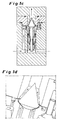
- FIG. 1a an inventive valve mixer is shown in longitudinal section.
- the valve mixer consists of a base body 1, a middle part 2 and a lid 3. These three components are sealed to the outside by two O-rings 4, 5.
- the first O-ring 4 is arranged between the base body 1 and the middle part 2
- the second O-ring 5 is located between the middle part 2 and the cover 3.
- the two partial flows 6, 7 occur from the left and from the right in the Basic body 1 a. They are each indicated by horizontally extending black arrows.
- the first partial flow 6 is guided in the left region of the main body 1 through a bore upwards, which opens into an annular channel 8 for the first partial flow 6.
- the first partial flow 6 occurs just above a valve tappet 9 in a mixing and reaction zone 10.
- the second partial flow 7 is guided centrally through the micromixer. It flows around the valve stem 9 and is supplied via a plurality of holes 12 of the underside of the head of the valve stem 9 and from there into the mixing and reaction zone 10.
- the reaction mixture consisting of the first partial flow 6 and the second partial flow 7, via an outlet channel 11 derived.
- the valve stem 9, the mixing and reaction zone 10 and the outlet channel 11 are rotationally symmetrical.
- This force must be applied by the pressure difference that exists between the pressure in the bores 12 for the second partial flow 7 and the mixing and reaction zone 10.
- the valve tappet 9 is displaced upward and clears the path for the second partial flow 7 into the mixing and reaction zone 10. If there is a pressure drop in the holes 12 or increases by deposits and blockages in the mixing and reaction zone 10 or in the outlet channel 11, the pressure strongly, the valve stem 9 is pressed down against the valve body 17, and a return flow from the mixing - And reaction zone 10 in the inlet region for the second partial stream 7 prevented.
- the micromixer is thus equipped with a non-return valve for the second partial flow 7 in the form of a check valve.
- the sealing effect can be further improved by that between the valve stem 9 and the valve body 17, an elastomeric seal is used, which is not shown here.
- the valve body 17 is sealed by a third O-ring 18 against the base body 1, so that a mixing of the two partial streams 6, 7 outside the mixing and reaction zone 10 is excluded.
- a flat spacer disk 16 Between the valve body 17 and the middle part 2 of the micromixer is a flat spacer disk 16, which is in different thicknesses, preferably in a thickness between 20 and 5000 microns, executed. By varying the pane thickness of the spacer disk 16, the width of the gap between the valve body 17 and the middle part 2, from which the first partial stream 6 flows into the mixing and reaction zone 10 changes.
- FIG. 1b provides an enlarged view of the environment of the mixing and reaction zone 10 of the micromixer of FIG. 1a
- the guidance of the two partial flows 6, 7 can be seen particularly clearly here.
- the first partial flow 6 passes from the annular channel 8 via a first entrance slit 19, whose width is determined by the spacer disk 16, in the mixing and reaction zone 10. Due to the uniform thickness of the first entrance slit 19 of the first partial stream 6 flows as a closed film of the Valve body 17 off. Behind this, the first partial flow 6 impinges on the second partial flow 7, which likewise emerges as a closed and uniform film.
- the second partial flow 7 exits from a second inlet gap 20 between the valve tappet 9 and the valve body 17.
- the two partial streams 6, 7 formed as films flow parallel to one another through the mixing and reaction zone 10 to the outlet channel 11. An improvement in the mixing quality is achieved when the spacer disk 16 is microstructured.
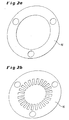
- FIGS. 1a and 1b each give the flow of the FIGS. 1a and 1b again. Reference signs have been omitted.
- the flow curves are each represented by the black arrows.
- Shims 16 are respectively shown, as used to adjust the height of the first entrance gap 19 between the valve body 17 and the middle part 2 for the first partial flow 6.
- the spacer 16 of the FIG. 2b is different from the one in the FIG. 2a in that it additionally has a microstructured configuration in the region of the first entry gap 19 for the first partial flow 6.
- By the spacer disk 16 in the FIG. 2b can be achieved an improvement in the mixing of the two partial streams 6, 7, since the closed film of the first partial stream 6 is decomposed into several individual beams and the speed of these individual beams at the first entrance slit 19 is significantly increased, so that the rays penetrate into the second partial flow 7 and be enclosed by it. In this way, the advantages of microtechnology for the production of small fluid fins are exploited without causing deposits and blockages of the microstructures.
- FIGS. 3a and 3b represent flow patterns in the mixing and reaction zone 10
- FIG. 3a a perspective view of the mixing and reaction zone 10, wherein a spacer disk 16 according to the FIG. 2b has been used.
- the first partial flow 6 is indicated by the black arrows 6, and the second partial flow 7 is represented by white arrows. It can be seen that the first partial flow 6 has been divided into a plurality of individual jets, which are respectively enclosed by the second partial flow 7.
- FIG. 3b is a cross section through the mixing and reaction zone 10 of FIG. 3a reproduced with the corresponding flow path of the first partial flow 6 and the second partial flow 7.
- the FIG. 4 illustrates a valve stem 9 with a structured micro-surface 21.
- the patterned micro-surface 21 is circled and enlarged on the right in a circle. Due to the structured micro-surface 21, the second partial flow 7, which otherwise emerges as a closed fluid film between the valve tappet 9 and the valve body 17 from the second inlet gap 20, is divided into a plurality of individual jets.
- the structures of the structured micro-surface 21 are preferably between 50 and 3000 microns high, and they are placed in the mixing and reaction zone 10 so that the webs connect with the valve stem 9 closed to the wall, so that the second partial flow 7 actually into separate individual jets is split. In this way, a field with very high velocity gradients is generated via the flow cross section of the second partial flow 7 measured. This favors the mixing of the first partial flow 6 with the second partial flow 7.
- FIGS. 5a to 5d each represent a longitudinal section through a micromixer with a check valve as Ragströmsperre.
- Die FIGS. 5a and 5b show a micromixer with a narrow first entrance nip 19.
- the check valve In the FIG. 5a the check valve is closed, and in the FIG. 5b the check valve is open and releases a second entrance slit 20 for the second partial flow 7.
- the FIGS. 5c and 5d represent a micromixer with a wide first entrance slit 19.
- the check valve is closed, and in the FIG. 5d the check valve is open and releases a second entrance slit 20 for the second partial flow 7.
- the first partial flow 6 experiences a much higher speed than in the case of FIG. 5d with a wide first entrance nip 19.
- the width of the first entrance nip 19 and thus also the width of the gap 30, in which the two partial streams 6, 7 converge, and in its extension downstream of the mixing and reaction zone, vary.
- FIG. 6a is a micromixer according to the invention with a membrane body 34 as Ragströmsperre seen in longitudinal section.
- this micromixer also comprises a main body 1, a central part 2 and a lid 3.
- the lid 3 is composed of upper and lower halves, and the middle part 2 is also composed of upper and lower parts.
- the second and the third partial flow 7, 37 are each fed via a non-return valve in the manner of a membrane body 34 to the mixing and reaction zone 10.
- different materials come into question. It can be adjusted by different wall thicknesses of the membrane body 34 and different elasticity of the material to be applied by the differential pressure required opening force. This is similar to the setting in the micromixer FIG.
- the micromixer with membrane body 34 either only a further partial stream or else two further partial streams 7, 37 can be added to your first partial stream 6. It is also conceivable that the first partial flow 6 carries particles with it. The particles can be the. Microstructure penetrate unhindered, since the micromixer has minimum dimensions in the range between 500 and 3,000 microns.
- FIG. 6b is an enlarged view of the FIG. 6a shown in the vicinity of the mixing and reaction zone 10.
- FIGS. 6c and 6d give the flow of the Figures 6a and 6b again. Reference signs have been omitted.
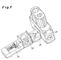
- FIG. 7 a designed as a valve mixer module 24 is shown, which is combined with a further metering point 26 and an electric heating module 27 to form an integrated component. Between the module 24 designed as a valve mixer and the further metering point 26, an insulation module 25 is provided for the thermal decoupling of these adjacent components.
- FIG. 8 represents an advantageous embodiment of the valve mixer with annular coaxial disorder of the entrance column 19, 20, wherein the remindströmsperre is formed in the region of the outer of the two inlet column.
- the return flow lock is realized here by an axially movable valve ring 41 which is sealed by a piston seal 42 relative to the housing 43 and is pressed by an occlusive force 45 against the opposite edge of the entrance slit 19. If the force exerted on the valve ring by the pressure of the first partial flow exceeds the closing force 45, the inlet gap 20 opens and the first partial flow enters the mixing and reaction zone 10.
- FIG. 9 is a further advantageous embodiment of the valve mixer with a ring-shaped coaxial arrangement of the entrance column 19, 20 shown, in which both in the region of the first and the second entrance gap, a return flow lock is formed.
- a return flow lock is formed.
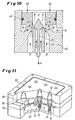
- FIG. 10 shows a likewise advantageous embodiment of the valve mixer, which consists of the in FIG. 9 illustrated embodiment is characterized in that the mixing and reaction zone 10, a third partial flow 37 through a further annular inlet gap 38 which is arranged between the entrance slit for the first 19 and the entrance slit 20 for the second partial flow is supplied.
- FIG. 11 is a parallel arrangement of several inventive valve mixer units in a common housing (51-53) shown with common supply of the partial flows, which can be advantageously used for the mixing of larger volume flows.
- the two supply channels for the first (56) and second partial flow (57) are arranged in this embodiment in two superimposed planes.
- the opening pressure of the check valve is individually variable in order to set a uniform volume flow ratio of the partial flows on all mixer units can.
- the mixture product leaves the individual mixing units in a common outlet channel, which in direct connection above in the FIG. 11 shown assembly is arranged.
Landscapes
- Engineering & Computer Science (AREA)
- General Engineering & Computer Science (AREA)
- Chemical & Material Sciences (AREA)
- Mechanical Engineering (AREA)
- Chemical Kinetics & Catalysis (AREA)
- Nanotechnology (AREA)
- Crystallography & Structural Chemistry (AREA)
- Materials Engineering (AREA)
- General Physics & Mathematics (AREA)
- Condensed Matter Physics & Semiconductors (AREA)
- Composite Materials (AREA)
- Physics & Mathematics (AREA)
- Physical Or Chemical Processes And Apparatus (AREA)
- Accessories For Mixers (AREA)
- Weting (AREA)
- Micromachines (AREA)
Priority Applications (1)
| Application Number | Priority Date | Filing Date | Title |
|---|---|---|---|
| EP05707247A EP1718402B1 (de) | 2004-02-17 | 2005-02-08 | Mikromischer |
Applications Claiming Priority (4)
| Application Number | Priority Date | Filing Date | Title |
|---|---|---|---|
| EP04003471A EP1666132A1 (de) | 2004-02-17 | 2004-02-17 | Mikromischer |
| DE102005003965A DE102005003965A1 (de) | 2005-01-27 | 2005-01-27 | Mikromischer |
| EP05707247A EP1718402B1 (de) | 2004-02-17 | 2005-02-08 | Mikromischer |
| PCT/EP2005/001227 WO2005079964A1 (de) | 2004-02-17 | 2005-02-08 | Mikromischer |
Publications (2)
| Publication Number | Publication Date |
|---|---|
| EP1718402A1 EP1718402A1 (de) | 2006-11-08 |
| EP1718402B1 true EP1718402B1 (de) | 2008-08-13 |
Family
ID=34888843
Family Applications (1)
| Application Number | Title | Priority Date | Filing Date |
|---|---|---|---|
| EP05707247A Active EP1718402B1 (de) | 2004-02-17 | 2005-02-08 | Mikromischer |
Country Status (8)
| Country | Link |
|---|---|
| US (1) | US7934865B2 (ja) |
| EP (1) | EP1718402B1 (ja) |
| JP (1) | JP4920427B2 (ja) |
| KR (1) | KR101186708B1 (ja) |
| CN (1) | CN1921931B (ja) |
| AT (1) | ATE404273T1 (ja) |
| DE (1) | DE502005005027D1 (ja) |
| WO (1) | WO2005079964A1 (ja) |
Families Citing this family (49)
| Publication number | Priority date | Publication date | Assignee | Title |
|---|---|---|---|---|
| JP4920427B2 (ja) | 2004-02-17 | 2012-04-18 | エーアフェルト・ミクロテッヒニク・ベーテーエス・ゲゼルシャフト・ミット・ベシュレンクテル・ハフツング | マイクロミキサー |
| US7622509B2 (en) | 2004-10-01 | 2009-11-24 | Velocys, Inc. | Multiphase mixing process using microchannel process technology |
| JP5704786B2 (ja) | 2004-11-16 | 2015-04-22 | ヴェロシス,インク. | マイクロチャネル技術を用いる多相反応プロセス |
| DE502004005576D1 (de) * | 2004-12-30 | 2008-01-03 | Grundfos Nonox As | Vorrichtung zur Erzeugung eines Reduktionsmittel-Luft-Gemisches |
| DE102005047758A1 (de) | 2005-09-28 | 2007-03-29 | Siemens Ag | Verfahren zum Durchführen einer Reaktion in einer Mikroreaktionskammer |
| DE102005049294C5 (de) | 2005-10-14 | 2012-05-03 | Ehrfeld Mikrotechnik Bts Gmbh | Verfahren zur Herstellung organischer Peroxide mittels Mikroreaktionstechnik |
| DE102005060280B4 (de) * | 2005-12-16 | 2018-12-27 | Ehrfeld Mikrotechnik Bts Gmbh | Integrierbarer Mikromischer sowie dessen Verwendung |
| JP2007268503A (ja) * | 2006-03-31 | 2007-10-18 | National Institute Of Advanced Industrial & Technology | 超臨界マイクロ混合デバイス |
| DE602007009175D1 (de) * | 2006-12-09 | 2010-10-28 | Haldor Topsoe As | Verfahren und Vorrichtung zum Mischen zweier oder mehrerer Fluidströme |
| DE102007014487A1 (de) * | 2007-03-22 | 2008-10-09 | Bayer Technology Services Gmbh | Strahldispergator |
| EP2095872A1 (en) * | 2008-02-29 | 2009-09-02 | Corning Incorporated | Injector assemblies and microreactors incorporating the same |
| US8187554B2 (en) * | 2008-04-23 | 2012-05-29 | Microfluidics International Corporation | Apparatus and methods for nanoparticle generation and process intensification of transport and reaction systems |
| JP2010247071A (ja) | 2009-04-16 | 2010-11-04 | Hitachi Plant Technologies Ltd | 流体混合器 |
| DE102009018539A1 (de) * | 2009-04-24 | 2010-11-18 | Bayer Technology Services Gmbh | Modulare Mischer |
| JP2011088108A (ja) * | 2009-10-26 | 2011-05-06 | Sugino Machine Ltd | 衝突装置 |
| CN101757864B (zh) * | 2010-02-09 | 2012-05-09 | 华北电力大学 | 一种气泡摆动式微混合系统 |
| EP2383245A3 (de) | 2010-04-20 | 2012-02-22 | Bayer Technology Services GmbH | Verfahren zur kontinuierlichen Oxidation von Thioethern |
| KR101324405B1 (ko) * | 2010-06-28 | 2013-11-01 | 디아이씨 가부시끼가이샤 | 마이크로 믹서 |
| WO2012025548A1 (en) | 2010-08-27 | 2012-03-01 | Solvay Sa | Process for the preparation of alkenones |
| CN102000518A (zh) * | 2010-09-27 | 2011-04-06 | 华北电力大学 | 一种微汽泡泵环路驱动的脉动流微混合系统 |
| US10350556B2 (en) * | 2011-01-07 | 2019-07-16 | Microfluidics International Corporation | Low holdup volume mixing chamber |
| US9079140B2 (en) | 2011-04-13 | 2015-07-14 | Microfluidics International Corporation | Compact interaction chamber with multiple cross micro impinging jets |
| US9199209B2 (en) * | 2011-04-13 | 2015-12-01 | Microfluidics International Corporation | Interaction chamber with flow inlet optimization |
| EP2664607A1 (en) | 2012-05-16 | 2013-11-20 | Solvay Sa | Fluorination process |
| FR2993791B1 (fr) * | 2012-07-27 | 2014-07-11 | Eveon | Distributeur fluidique et dispositif de reconstitution in situ et d'administration |
| CN103322247A (zh) * | 2013-06-09 | 2013-09-25 | 安徽艾可蓝节能环保科技有限公司 | 一种气液混合腔逆向止流装置 |
| JP6280704B2 (ja) * | 2013-07-23 | 2018-02-14 | Kyb株式会社 | 制御バルブ |
| GB2519171B (en) | 2013-10-14 | 2016-02-17 | Redd & Whyte Ltd | Micro-Valve |
| CN103585909A (zh) * | 2013-11-20 | 2014-02-19 | 北京工商大学 | 锥封微射流均质阀 |
| JP2015201646A (ja) | 2014-04-07 | 2015-11-12 | ラム リサーチ コーポレーションLam Research Corporation | 構成独立型のガス供給システム |
| CN105457512B (zh) * | 2014-09-12 | 2018-03-02 | 泉州市汇辰产品设计有限公司 | 一种液体混合器 |
| CN105457515B (zh) * | 2014-09-12 | 2017-08-25 | 中山市雅西环保科技有限公司 | 一种同步混合装置 |
| US10557197B2 (en) | 2014-10-17 | 2020-02-11 | Lam Research Corporation | Monolithic gas distribution manifold and various construction techniques and use cases therefor |
| DE102015006727A1 (de) * | 2015-05-30 | 2016-12-01 | Rainer Pommersheim | Verfahren und technischer Prozess zur Herstellung von Mikro- und Nanopartikeln unterschiedlicher Größe |
| WO2017009161A1 (en) | 2015-07-10 | 2017-01-19 | Covestro Deutschland Ag | Process and apparatus for continuous production of aqueous polyurethane dispersions |
| US10022689B2 (en) * | 2015-07-24 | 2018-07-17 | Lam Research Corporation | Fluid mixing hub for semiconductor processing tool |
| US10215317B2 (en) | 2016-01-15 | 2019-02-26 | Lam Research Corporation | Additively manufactured gas distribution manifold |
| DE102016108872A1 (de) * | 2016-05-13 | 2017-11-30 | Karlsruher Institut für Technologie | Vorrichtung und Verfahren für die Durchführung von Fällungsreaktionen unter Beteiligung von mindestens zwei Ausgangsprodukten |
| CN106195347B (zh) * | 2016-07-11 | 2018-12-04 | 常州大学 | 一种设有储液器的防冰堵的自动注液节流阀 |
| US10627001B2 (en) * | 2018-06-29 | 2020-04-21 | Sulzer Mixpac Ag | Check valve system |
| EP3804704A1 (de) | 2019-10-10 | 2021-04-14 | Bayer AG | Verfahren zur herstellung nanopartikulären rivaroxabans |
| EP4041203A1 (en) | 2019-10-10 | 2022-08-17 | Bayer Aktiengesellschaft | Process for the preparation of a nanoparticulate active ingredient |
| EP3804703A1 (de) | 2019-10-10 | 2021-04-14 | Bayer AG | Verfahren zur herstellung eines nanopartikulären wirkstoffs |
| DE102020104325A1 (de) * | 2020-02-19 | 2021-08-19 | Dürr Systems Ag | Spülvorrichtung zum Verbinden mit einem Applikationsmittel-Hauptkanal eines Applikationsmittelwechslers |
| CN111558113B (zh) * | 2020-04-30 | 2021-09-24 | 北京快舒尔医疗技术有限公司 | 无针注射器主体和无针注射器 |
| CN111558112B (zh) * | 2020-04-30 | 2021-09-24 | 北京快舒尔医疗技术有限公司 | 无针注射器的注射头、无针注射器主体和无针注射器 |
| CN111661470A (zh) * | 2020-06-24 | 2020-09-15 | 沈胜洲 | 一种便于使用的物料出料装置 |
| CN112844148B (zh) * | 2021-03-02 | 2022-12-09 | 江苏永邦智能装备科技有限公司 | 一种石墨烯原料混均设备 |
| CN114962844B (zh) * | 2022-04-26 | 2023-07-21 | 重庆海浦洛自动化科技有限公司 | 高粘度介质用蓄能装置及其使用方法 |
Family Cites Families (30)
| Publication number | Priority date | Publication date | Assignee | Title |
|---|---|---|---|---|
| US154544A (en) * | 1874-09-01 | Improvement in feed-water heaters | ||
| US401021A (en) * | 1889-04-09 | fellowes | ||
| FR1161144A (fr) * | 1956-01-12 | 1958-08-21 | Perfectionnements apportés aux vannes pour mélanger des fluides ayant des températures différentes | |
| US3540474A (en) * | 1968-04-01 | 1970-11-17 | Beckman Instruments Inc | Rapid mixer |
| US4051769A (en) * | 1975-08-27 | 1977-10-04 | The B. F. Goodrich Company | Solar powered method and apparatus for venting gaseous material from an enclosed space to atmosphere |
| FR2343179A1 (fr) * | 1976-03-05 | 1977-09-30 | Poclain Sa | Clapet de decharge tare et dispositif de reglage a distance de tarages |
| AU668147B2 (en) | 1992-03-17 | 1996-04-26 | Nordson Corporation | Two-component dispensing system |
| DE4243860C2 (de) * | 1992-12-23 | 1995-02-23 | Imm Inst Mikrotech | Mikrominiaturisierte, elektrostatische Pumpe und Verfahren zu deren Herstellung |
| US5874644A (en) | 1996-04-12 | 1999-02-23 | Gammill; Ben | Method and system for bisphenol a production using controlled turbulence |
| DE19707165A1 (de) * | 1997-02-22 | 1998-08-27 | Gelhard Volker Dipl Ing Dipl W | Vorrichtung und Verfahren zum Vermischen eines ersten Fluids mit einem zweiten Fluid |
| FR2770151B1 (fr) | 1997-10-28 | 2001-06-22 | Atochem Elf Sa | Procede et dispositif pour le micromelange de fluides en continu et leur utilisation, notamment pour des reactions de polymerisation |
| WO2000061275A2 (de) | 1999-04-08 | 2000-10-19 | Bernd Penth | Verfahren und vorrichtung zur durchführung chemischer und physikalischer prozesse |
| EP1127606A1 (en) | 2000-02-24 | 2001-08-29 | Stichting Energieonderzoek Centrum Nederland(ECN) | Membrane module for the separation of fluid mixtures |
| JP4927287B2 (ja) * | 2000-03-31 | 2012-05-09 | マイクロニックス、インコーポレーテッド | タンパク質の結晶化のマイクロ流動体装置 |
| US6520197B2 (en) * | 2000-06-02 | 2003-02-18 | The Regents Of The University Of California | Continuous laminar fluid mixing in micro-electromechanical systems |
| DE10031558A1 (de) | 2000-06-28 | 2002-01-10 | Clariant Gmbh | Verfahren zur Konditionierung von organischen Pigmenten |
| US6644944B2 (en) * | 2000-11-06 | 2003-11-11 | Nanostream, Inc. | Uni-directional flow microfluidic components |
| FR2818727B1 (fr) * | 2000-12-21 | 2004-12-17 | Taema | Soupape a amplification d'ouverture et regulateur de pression equipe d'une telle soupape |
| DE10119718A1 (de) | 2001-04-21 | 2002-10-31 | Boehringer Ingelheim Pharma | Verfahren zur kontinuierlichen Herstellung inhalierfähiger Arzneistoffe, Vorrichtung zur Durchführung des Verfahrens und nach diesem Verfahren hergestellter Arzneistoff |
| DE10143189A1 (de) | 2001-09-04 | 2003-03-20 | Clariant Gmbh | Verfahren und Vorrichtung zur prozeßbegleitenden Reinigung von Mikro-und Minireaktoren |
| DE10148615B4 (de) | 2001-09-26 | 2005-03-31 | INSTITUT FüR MIKROTECHNIK MAINZ GMBH | Verfahren und Vorrichtung zur Durchführung chemischer Prozesse |
| US6939032B2 (en) * | 2001-10-25 | 2005-09-06 | Erie Scientific Company | Cover slip mixing apparatus |
| US20030175947A1 (en) * | 2001-11-05 | 2003-09-18 | Liu Robin Hui | Enhanced mixing in microfluidic devices |
| JP3727595B2 (ja) * | 2002-01-18 | 2005-12-14 | 富士写真フイルム株式会社 | マイクロミキサー |
| US20040008572A1 (en) * | 2002-07-09 | 2004-01-15 | Stuart Joseph Y. | Coaxial jet mixer nozzle with protruding centerbody and method for mixing two or more fluid components |
| JP2004069498A (ja) | 2002-08-06 | 2004-03-04 | Canon Inc | 液体搬送装置及び液体搬送方法 |
| EP1545780B1 (en) * | 2002-09-06 | 2007-02-28 | Epigem Limited | Modular microfluidic system |
| DE20218972U1 (de) | 2002-12-07 | 2003-02-13 | Ehrfeld Mikrotechnik Ag | Statischer Laminationsmikrovermischer |
| US20050047967A1 (en) * | 2003-09-03 | 2005-03-03 | Industrial Technology Research Institute | Microfluidic component providing multi-directional fluid movement |
| JP4920427B2 (ja) | 2004-02-17 | 2012-04-18 | エーアフェルト・ミクロテッヒニク・ベーテーエス・ゲゼルシャフト・ミット・ベシュレンクテル・ハフツング | マイクロミキサー |
-
2005
- 2005-02-08 JP JP2006553487A patent/JP4920427B2/ja active Active
- 2005-02-08 US US10/587,404 patent/US7934865B2/en active Active
- 2005-02-08 EP EP05707247A patent/EP1718402B1/de active Active
- 2005-02-08 AT AT05707247T patent/ATE404273T1/de active
- 2005-02-08 CN CN200580005265XA patent/CN1921931B/zh active Active
- 2005-02-08 KR KR1020067016426A patent/KR101186708B1/ko active IP Right Grant
- 2005-02-08 DE DE502005005027T patent/DE502005005027D1/de active Active
- 2005-02-08 WO PCT/EP2005/001227 patent/WO2005079964A1/de active IP Right Grant
Also Published As
| Publication number | Publication date |
|---|---|
| DE502005005027D1 (de) | 2008-09-25 |
| EP1718402A1 (de) | 2006-11-08 |
| JP4920427B2 (ja) | 2012-04-18 |
| ATE404273T1 (de) | 2008-08-15 |
| CN1921931A (zh) | 2007-02-28 |
| CN1921931B (zh) | 2012-05-09 |
| US20070291581A1 (en) | 2007-12-20 |
| KR101186708B1 (ko) | 2012-09-27 |
| KR20070009563A (ko) | 2007-01-18 |
| US7934865B2 (en) | 2011-05-03 |
| WO2005079964A1 (de) | 2005-09-01 |
| JP2007525319A (ja) | 2007-09-06 |
Similar Documents
| Publication | Publication Date | Title |
|---|---|---|
| EP1718402B1 (de) | Mikromischer | |
| EP1613424B1 (de) | Mikroreaktor in plattenbauweise mit einem katalysator | |
| DE19917148C2 (de) | Verfahren und Mikrovermischer zur Herstellung einer Dispersion | |
| EP1658129B1 (de) | Statischer mikromischer | |
| DE10041823C2 (de) | Verfahren und statischer Mikrovermischer zum Mischen mindestens zweier Fluide | |
| WO2010099884A1 (de) | Koaxialer kompaktstatikmischer sowie dessen verwendung | |
| WO1998033582A1 (de) | Verfahren und vorrichtung zur herstellung eines dispersen gemisches | |
| EP1165224A2 (de) | Verfahren und vorrichtung zur durchführung chemischer und physikalischer prozesse | |
| DE19928123A1 (de) | Statischer Mikrovermischer | |
| DE102005015433A1 (de) | Mischersystem, Reaktor und Reaktorsystem | |
| EP1648581B1 (de) | Extraktionsverfahren unter verwendung eines statischen mikromischers | |
| DE10123092B4 (de) | Verfahren und statischer Mischer zum Mischen mindestens zweier Fluide | |
| WO1996009112A1 (de) | Vorrichtung zur erzeugung flüssiger systeme, insbesondere von emulsionen, suspensionen od. dgl. in einem hydrodynamischen kavitationsfeld | |
| WO2018234217A1 (de) | Fluidreaktor | |
| EP2915581B1 (de) | Statischer Mischer | |
| WO2003068381A1 (de) | Verfahren zum erzeugen monodisperser nanotropfen oder nanopartikel und zwei vorrichtungen zur durchführung des verfahrens | |
| WO2004098758A1 (de) | Dispergiervorrichtung | |
| DE60311667T2 (de) | Fluidbehandlungsvorrichtung mit ringförmigen strömungswegen, system und verfahren | |
| EP1666132A1 (de) | Mikromischer | |
| DE102005003965A1 (de) | Mikromischer | |
| DE202006001952U1 (de) | Vorrichtung zum Herstellen von Dispersionen | |
| EP2315627A1 (de) | Verfahren zur herstellung von nanoskaligen organischen feststoffpartikeln | |
| EP2129454B1 (de) | Strahldispergator | |
| EP1933977A1 (de) | Dehnströmungs-trennschicht-reaktor | |
| DE102005060280B4 (de) | Integrierbarer Mikromischer sowie dessen Verwendung |
Legal Events
| Date | Code | Title | Description |
|---|---|---|---|
| PUAI | Public reference made under article 153(3) epc to a published international application that has entered the european phase |
Free format text: ORIGINAL CODE: 0009012 |
|
| 17P | Request for examination filed |
Effective date: 20060918 |
|
| AK | Designated contracting states |
Kind code of ref document: A1 Designated state(s): AT BE BG CH CY CZ DE DK EE ES FI FR GB GR HU IE IS IT LI LT LU MC NL PL PT RO SE SI SK TR |
|
| 17Q | First examination report despatched |
Effective date: 20070411 |
|
| DAX | Request for extension of the european patent (deleted) | ||
| GRAP | Despatch of communication of intention to grant a patent |
Free format text: ORIGINAL CODE: EPIDOSNIGR1 |
|
| GRAS | Grant fee paid |
Free format text: ORIGINAL CODE: EPIDOSNIGR3 |
|
| GRAA | (expected) grant |
Free format text: ORIGINAL CODE: 0009210 |
|
| AK | Designated contracting states |
Kind code of ref document: B1 Designated state(s): AT BE BG CH CY CZ DE DK EE ES FI FR GB GR HU IE IS IT LI LT LU MC NL PL PT RO SE SI SK TR |
|
| REG | Reference to a national code |
Ref country code: GB Ref legal event code: FG4D Free format text: NOT ENGLISH |
|
| REG | Reference to a national code |
Ref country code: CH Ref legal event code: EP |
|
| REG | Reference to a national code |
Ref country code: CH Ref legal event code: NV Representative=s name: E. BLUM & CO. AG PATENT- UND MARKENANWAELTE VSP |
|
| REG | Reference to a national code |
Ref country code: IE Ref legal event code: FG4D Free format text: LANGUAGE OF EP DOCUMENT: GERMAN |
|
| REF | Corresponds to: |
Ref document number: 502005005027 Country of ref document: DE Date of ref document: 20080925 Kind code of ref document: P |
|
| PG25 | Lapsed in a contracting state [announced via postgrant information from national office to epo] |
Ref country code: IS Free format text: LAPSE BECAUSE OF FAILURE TO SUBMIT A TRANSLATION OF THE DESCRIPTION OR TO PAY THE FEE WITHIN THE PRESCRIBED TIME-LIMIT Effective date: 20081213 Ref country code: LT Free format text: LAPSE BECAUSE OF FAILURE TO SUBMIT A TRANSLATION OF THE DESCRIPTION OR TO PAY THE FEE WITHIN THE PRESCRIBED TIME-LIMIT Effective date: 20080813 |
|
| PG25 | Lapsed in a contracting state [announced via postgrant information from national office to epo] |
Ref country code: SI Free format text: LAPSE BECAUSE OF FAILURE TO SUBMIT A TRANSLATION OF THE DESCRIPTION OR TO PAY THE FEE WITHIN THE PRESCRIBED TIME-LIMIT Effective date: 20080813 Ref country code: FI Free format text: LAPSE BECAUSE OF FAILURE TO SUBMIT A TRANSLATION OF THE DESCRIPTION OR TO PAY THE FEE WITHIN THE PRESCRIBED TIME-LIMIT Effective date: 20080813 Ref country code: ES Free format text: LAPSE BECAUSE OF FAILURE TO SUBMIT A TRANSLATION OF THE DESCRIPTION OR TO PAY THE FEE WITHIN THE PRESCRIBED TIME-LIMIT Effective date: 20081124 |
|
| REG | Reference to a national code |
Ref country code: IE Ref legal event code: FD4D |
|
| PG25 | Lapsed in a contracting state [announced via postgrant information from national office to epo] |
Ref country code: IE Free format text: LAPSE BECAUSE OF FAILURE TO SUBMIT A TRANSLATION OF THE DESCRIPTION OR TO PAY THE FEE WITHIN THE PRESCRIBED TIME-LIMIT Effective date: 20080813 Ref country code: BG Free format text: LAPSE BECAUSE OF FAILURE TO SUBMIT A TRANSLATION OF THE DESCRIPTION OR TO PAY THE FEE WITHIN THE PRESCRIBED TIME-LIMIT Effective date: 20081113 Ref country code: DK Free format text: LAPSE BECAUSE OF FAILURE TO SUBMIT A TRANSLATION OF THE DESCRIPTION OR TO PAY THE FEE WITHIN THE PRESCRIBED TIME-LIMIT Effective date: 20080813 |
|
| PG25 | Lapsed in a contracting state [announced via postgrant information from national office to epo] |
Ref country code: PT Free format text: LAPSE BECAUSE OF FAILURE TO SUBMIT A TRANSLATION OF THE DESCRIPTION OR TO PAY THE FEE WITHIN THE PRESCRIBED TIME-LIMIT Effective date: 20090113 Ref country code: CZ Free format text: LAPSE BECAUSE OF FAILURE TO SUBMIT A TRANSLATION OF THE DESCRIPTION OR TO PAY THE FEE WITHIN THE PRESCRIBED TIME-LIMIT Effective date: 20080813 Ref country code: SK Free format text: LAPSE BECAUSE OF FAILURE TO SUBMIT A TRANSLATION OF THE DESCRIPTION OR TO PAY THE FEE WITHIN THE PRESCRIBED TIME-LIMIT Effective date: 20080813 Ref country code: RO Free format text: LAPSE BECAUSE OF FAILURE TO SUBMIT A TRANSLATION OF THE DESCRIPTION OR TO PAY THE FEE WITHIN THE PRESCRIBED TIME-LIMIT Effective date: 20080813 |
|
| PLBE | No opposition filed within time limit |
Free format text: ORIGINAL CODE: 0009261 |
|
| STAA | Information on the status of an ep patent application or granted ep patent |
Free format text: STATUS: NO OPPOSITION FILED WITHIN TIME LIMIT |
|
| 26N | No opposition filed |
Effective date: 20090514 |
|
| PG25 | Lapsed in a contracting state [announced via postgrant information from national office to epo] |
Ref country code: EE Free format text: LAPSE BECAUSE OF FAILURE TO SUBMIT A TRANSLATION OF THE DESCRIPTION OR TO PAY THE FEE WITHIN THE PRESCRIBED TIME-LIMIT Effective date: 20080813 |
|
| PG25 | Lapsed in a contracting state [announced via postgrant information from national office to epo] |
Ref country code: IT Free format text: LAPSE BECAUSE OF FAILURE TO SUBMIT A TRANSLATION OF THE DESCRIPTION OR TO PAY THE FEE WITHIN THE PRESCRIBED TIME-LIMIT Effective date: 20080813 |
|
| PG25 | Lapsed in a contracting state [announced via postgrant information from national office to epo] |
Ref country code: MC Free format text: LAPSE BECAUSE OF NON-PAYMENT OF DUE FEES Effective date: 20090228 |
|
| PG25 | Lapsed in a contracting state [announced via postgrant information from national office to epo] |
Ref country code: SE Free format text: LAPSE BECAUSE OF FAILURE TO SUBMIT A TRANSLATION OF THE DESCRIPTION OR TO PAY THE FEE WITHIN THE PRESCRIBED TIME-LIMIT Effective date: 20081113 |
|
| PG25 | Lapsed in a contracting state [announced via postgrant information from national office to epo] |
Ref country code: PL Free format text: LAPSE BECAUSE OF FAILURE TO SUBMIT A TRANSLATION OF THE DESCRIPTION OR TO PAY THE FEE WITHIN THE PRESCRIBED TIME-LIMIT Effective date: 20080813 |
|
| PG25 | Lapsed in a contracting state [announced via postgrant information from national office to epo] |
Ref country code: GR Free format text: LAPSE BECAUSE OF FAILURE TO SUBMIT A TRANSLATION OF THE DESCRIPTION OR TO PAY THE FEE WITHIN THE PRESCRIBED TIME-LIMIT Effective date: 20081114 |
|
| PG25 | Lapsed in a contracting state [announced via postgrant information from national office to epo] |
Ref country code: LU Free format text: LAPSE BECAUSE OF NON-PAYMENT OF DUE FEES Effective date: 20090208 |
|
| PG25 | Lapsed in a contracting state [announced via postgrant information from national office to epo] |
Ref country code: HU Free format text: LAPSE BECAUSE OF FAILURE TO SUBMIT A TRANSLATION OF THE DESCRIPTION OR TO PAY THE FEE WITHIN THE PRESCRIBED TIME-LIMIT Effective date: 20090214 |
|
| PG25 | Lapsed in a contracting state [announced via postgrant information from national office to epo] |
Ref country code: TR Free format text: LAPSE BECAUSE OF FAILURE TO SUBMIT A TRANSLATION OF THE DESCRIPTION OR TO PAY THE FEE WITHIN THE PRESCRIBED TIME-LIMIT Effective date: 20080813 |
|
| PG25 | Lapsed in a contracting state [announced via postgrant information from national office to epo] |
Ref country code: CY Free format text: LAPSE BECAUSE OF FAILURE TO SUBMIT A TRANSLATION OF THE DESCRIPTION OR TO PAY THE FEE WITHIN THE PRESCRIBED TIME-LIMIT Effective date: 20080813 |
|
| REG | Reference to a national code |
Ref country code: FR Ref legal event code: PLFP Year of fee payment: 12 |
|
| REG | Reference to a national code |
Ref country code: FR Ref legal event code: PLFP Year of fee payment: 13 |
|
| REG | Reference to a national code |
Ref country code: DE Ref legal event code: R082 Ref document number: 502005005027 Country of ref document: DE Representative=s name: COHAUSZ & FLORACK PATENT- UND RECHTSANWAELTE P, DE |
|
| REG | Reference to a national code |
Ref country code: FR Ref legal event code: PLFP Year of fee payment: 14 |
|
| REG | Reference to a national code |
Ref country code: DE Ref legal event code: R079 Ref document number: 502005005027 Country of ref document: DE Free format text: PREVIOUS MAIN CLASS: B01F0005000000 Ipc: B01F0025000000 |
|
| PGFP | Annual fee paid to national office [announced via postgrant information from national office to epo] |
Ref country code: FR Payment date: 20230223 Year of fee payment: 19 |
|
| PGFP | Annual fee paid to national office [announced via postgrant information from national office to epo] |
Ref country code: BE Payment date: 20230223 Year of fee payment: 19 |
|
| P01 | Opt-out of the competence of the unified patent court (upc) registered |
Effective date: 20230517 |
|
| PGFP | Annual fee paid to national office [announced via postgrant information from national office to epo] |
Ref country code: NL Payment date: 20240220 Year of fee payment: 20 |
|
| PGFP | Annual fee paid to national office [announced via postgrant information from national office to epo] |
Ref country code: AT Payment date: 20240222 Year of fee payment: 20 |
|
| PGFP | Annual fee paid to national office [announced via postgrant information from national office to epo] |
Ref country code: DE Payment date: 20240220 Year of fee payment: 20 Ref country code: GB Payment date: 20240220 Year of fee payment: 20 Ref country code: CH Payment date: 20240301 Year of fee payment: 20 |