EP1718402B1 - Micromixer - Google Patents
Micromixer Download PDFInfo
- Publication number
- EP1718402B1 EP1718402B1 EP05707247A EP05707247A EP1718402B1 EP 1718402 B1 EP1718402 B1 EP 1718402B1 EP 05707247 A EP05707247 A EP 05707247A EP 05707247 A EP05707247 A EP 05707247A EP 1718402 B1 EP1718402 B1 EP 1718402B1
- Authority
- EP
- European Patent Office
- Prior art keywords
- mixing
- micromixer
- flow
- sub
- reaction zone
- Prior art date
- Legal status (The legal status is an assumption and is not a legal conclusion. Google has not performed a legal analysis and makes no representation as to the accuracy of the status listed.)
- Active
Links
- 238000002156 mixing Methods 0.000 claims abstract description 77
- 238000006243 chemical reaction Methods 0.000 claims abstract description 60
- 239000012530 fluid Substances 0.000 claims abstract description 30
- 238000001556 precipitation Methods 0.000 claims abstract description 15
- 239000000725 suspension Substances 0.000 claims abstract description 8
- 239000002245 particle Substances 0.000 claims description 21
- 238000000034 method Methods 0.000 claims description 17
- 238000004140 cleaning Methods 0.000 claims description 11
- 230000008569 process Effects 0.000 claims description 11
- 238000002425 crystallisation Methods 0.000 claims description 10
- 230000008025 crystallization Effects 0.000 claims description 10
- 239000012528 membrane Substances 0.000 claims description 9
- 230000004888 barrier function Effects 0.000 claims description 8
- 239000002105 nanoparticle Substances 0.000 claims description 8
- 239000002244 precipitate Substances 0.000 claims description 5
- 239000000126 substance Substances 0.000 claims description 5
- 238000002360 preparation method Methods 0.000 claims description 4
- OKTJSMMVPCPJKN-UHFFFAOYSA-N Carbon Chemical compound [C] OKTJSMMVPCPJKN-UHFFFAOYSA-N 0.000 claims description 2
- 239000002041 carbon nanotube Substances 0.000 claims description 2
- 229910021393 carbon nanotube Inorganic materials 0.000 claims description 2
- 230000004044 response Effects 0.000 claims description 2
- 238000010992 reflux Methods 0.000 claims 7
- XMWRBQBLMFGWIX-UHFFFAOYSA-N C60 fullerene Chemical class C12=C3C(C4=C56)=C7C8=C5C5=C9C%10=C6C6=C4C1=C1C4=C6C6=C%10C%10=C9C9=C%11C5=C8C5=C8C7=C3C3=C7C2=C1C1=C2C4=C6C4=C%10C6=C9C9=C%11C5=C5C8=C3C3=C7C1=C1C2=C4C6=C2C9=C5C3=C12 XMWRBQBLMFGWIX-UHFFFAOYSA-N 0.000 claims 1
- 229910003472 fullerene Inorganic materials 0.000 claims 1
- 239000010409 thin film Substances 0.000 claims 1
- 230000036961 partial effect Effects 0.000 abstract description 88
- 230000002265 prevention Effects 0.000 abstract 1
- 239000000047 product Substances 0.000 description 16
- 125000006850 spacer group Chemical group 0.000 description 10
- 239000007789 gas Substances 0.000 description 7
- 238000010899 nucleation Methods 0.000 description 7
- 230000006911 nucleation Effects 0.000 description 7
- 239000007787 solid Substances 0.000 description 7
- 238000004519 manufacturing process Methods 0.000 description 6
- 239000000463 material Substances 0.000 description 6
- 239000000203 mixture Substances 0.000 description 6
- 230000008901 benefit Effects 0.000 description 5
- 238000013461 design Methods 0.000 description 5
- 239000007788 liquid Substances 0.000 description 5
- 230000000694 effects Effects 0.000 description 4
- 230000015572 biosynthetic process Effects 0.000 description 3
- 239000007795 chemical reaction product Substances 0.000 description 3
- 238000005485 electric heating Methods 0.000 description 3
- 238000002347 injection Methods 0.000 description 3
- 239000007924 injection Substances 0.000 description 3
- 238000007789 sealing Methods 0.000 description 3
- 238000000926 separation method Methods 0.000 description 3
- MCMNRKCIXSYSNV-UHFFFAOYSA-N Zirconium dioxide Chemical compound O=[Zr]=O MCMNRKCIXSYSNV-UHFFFAOYSA-N 0.000 description 2
- IISBACLAFKSPIT-UHFFFAOYSA-N bisphenol A Chemical compound C=1C=C(O)C=CC=1C(C)(C)C1=CC=C(O)C=C1 IISBACLAFKSPIT-UHFFFAOYSA-N 0.000 description 2
- 238000010276 construction Methods 0.000 description 2
- 239000013078 crystal Substances 0.000 description 2
- 230000003670 easy-to-clean Effects 0.000 description 2
- 239000000839 emulsion Substances 0.000 description 2
- 230000006872 improvement Effects 0.000 description 2
- 238000009413 insulation Methods 0.000 description 2
- 238000004886 process control Methods 0.000 description 2
- 239000002904 solvent Substances 0.000 description 2
- 238000012546 transfer Methods 0.000 description 2
- QGZKDVFQNNGYKY-UHFFFAOYSA-N Ammonia Chemical compound N QGZKDVFQNNGYKY-UHFFFAOYSA-N 0.000 description 1
- 229910052581 Si3N4 Inorganic materials 0.000 description 1
- RTAQQCXQSZGOHL-UHFFFAOYSA-N Titanium Chemical compound [Ti] RTAQQCXQSZGOHL-UHFFFAOYSA-N 0.000 description 1
- 238000010521 absorption reaction Methods 0.000 description 1
- 230000001133 acceleration Effects 0.000 description 1
- 239000002253 acid Substances 0.000 description 1
- 239000004480 active ingredient Substances 0.000 description 1
- 239000013543 active substance Substances 0.000 description 1
- 230000001154 acute effect Effects 0.000 description 1
- 230000002411 adverse Effects 0.000 description 1
- 229910045601 alloy Inorganic materials 0.000 description 1
- 239000000956 alloy Substances 0.000 description 1
- PNEYBMLMFCGWSK-UHFFFAOYSA-N aluminium oxide Inorganic materials [O-2].[O-2].[O-2].[Al+3].[Al+3] PNEYBMLMFCGWSK-UHFFFAOYSA-N 0.000 description 1
- 238000000149 argon plasma sintering Methods 0.000 description 1
- 230000009286 beneficial effect Effects 0.000 description 1
- 230000002051 biphasic effect Effects 0.000 description 1
- 230000001914 calming effect Effects 0.000 description 1
- 230000015556 catabolic process Effects 0.000 description 1
- 230000003197 catalytic effect Effects 0.000 description 1
- 229910010293 ceramic material Inorganic materials 0.000 description 1
- 238000001311 chemical methods and process Methods 0.000 description 1
- 239000012295 chemical reaction liquid Substances 0.000 description 1
- 230000003750 conditioning effect Effects 0.000 description 1
- 238000001816 cooling Methods 0.000 description 1
- PMHQVHHXPFUNSP-UHFFFAOYSA-M copper(1+);methylsulfanylmethane;bromide Chemical compound Br[Cu].CSC PMHQVHHXPFUNSP-UHFFFAOYSA-M 0.000 description 1
- 230000001419 dependent effect Effects 0.000 description 1
- 238000009792 diffusion process Methods 0.000 description 1
- 238000010790 dilution Methods 0.000 description 1
- 239000012895 dilution Substances 0.000 description 1
- 239000003814 drug Substances 0.000 description 1
- 229940079593 drug Drugs 0.000 description 1
- 238000009760 electrical discharge machining Methods 0.000 description 1
- 238000005516 engineering process Methods 0.000 description 1
- 230000005284 excitation Effects 0.000 description 1
- 230000007717 exclusion Effects 0.000 description 1
- 230000002349 favourable effect Effects 0.000 description 1
- 238000001595 flow curve Methods 0.000 description 1
- 238000000227 grinding Methods 0.000 description 1
- 229930195733 hydrocarbon Natural products 0.000 description 1
- 150000002430 hydrocarbons Chemical class 0.000 description 1
- 230000001771 impaired effect Effects 0.000 description 1
- 238000011065 in-situ storage Methods 0.000 description 1
- 239000003112 inhibitor Substances 0.000 description 1
- 150000002484 inorganic compounds Chemical class 0.000 description 1
- 229910010272 inorganic material Inorganic materials 0.000 description 1
- 239000012212 insulator Substances 0.000 description 1
- 230000010354 integration Effects 0.000 description 1
- 230000001788 irregular Effects 0.000 description 1
- 238000003475 lamination Methods 0.000 description 1
- 238000003754 machining Methods 0.000 description 1
- 238000005259 measurement Methods 0.000 description 1
- 238000010327 methods by industry Methods 0.000 description 1
- 239000003595 mist Substances 0.000 description 1
- 239000000178 monomer Substances 0.000 description 1
- 238000003541 multi-stage reaction Methods 0.000 description 1
- 239000006070 nanosuspension Substances 0.000 description 1
- 238000006386 neutralization reaction Methods 0.000 description 1
- 230000003287 optical effect Effects 0.000 description 1
- 150000002894 organic compounds Chemical class 0.000 description 1
- 239000012860 organic pigment Substances 0.000 description 1
- 230000000737 periodic effect Effects 0.000 description 1
- 230000000704 physical effect Effects 0.000 description 1
- 229920000642 polymer Polymers 0.000 description 1
- 238000006116 polymerization reaction Methods 0.000 description 1
- 239000004810 polytetrafluoroethylene Substances 0.000 description 1
- 229920001343 polytetrafluoroethylene Polymers 0.000 description 1
- 238000010944 pre-mature reactiony Methods 0.000 description 1
- 230000036316 preload Effects 0.000 description 1
- 238000010903 primary nucleation Methods 0.000 description 1
- 238000012545 processing Methods 0.000 description 1
- 230000005855 radiation Effects 0.000 description 1
- 239000011541 reaction mixture Substances 0.000 description 1
- 230000002829 reductive effect Effects 0.000 description 1
- 230000011218 segmentation Effects 0.000 description 1
- HBMJWWWQQXIZIP-UHFFFAOYSA-N silicon carbide Chemical compound [Si+]#[C-] HBMJWWWQQXIZIP-UHFFFAOYSA-N 0.000 description 1
- 229910010271 silicon carbide Inorganic materials 0.000 description 1
- HQVNEWCFYHHQES-UHFFFAOYSA-N silicon nitride Chemical compound N12[Si]34N5[Si]62N3[Si]51N64 HQVNEWCFYHHQES-UHFFFAOYSA-N 0.000 description 1
- 239000012265 solid product Substances 0.000 description 1
- 239000000243 solution Substances 0.000 description 1
- 239000003381 stabilizer Substances 0.000 description 1
- 229910001220 stainless steel Inorganic materials 0.000 description 1
- 230000003068 static effect Effects 0.000 description 1
- 238000003756 stirring Methods 0.000 description 1
- 238000003786 synthesis reaction Methods 0.000 description 1
- 229910052715 tantalum Inorganic materials 0.000 description 1
- GUVRBAGPIYLISA-UHFFFAOYSA-N tantalum atom Chemical compound [Ta] GUVRBAGPIYLISA-UHFFFAOYSA-N 0.000 description 1
- 229910052719 titanium Inorganic materials 0.000 description 1
- 239000010936 titanium Substances 0.000 description 1
- 230000001960 triggered effect Effects 0.000 description 1
Images


Classifications
-
- B—PERFORMING OPERATIONS; TRANSPORTING
- B01—PHYSICAL OR CHEMICAL PROCESSES OR APPARATUS IN GENERAL
- B01F—MIXING, e.g. DISSOLVING, EMULSIFYING OR DISPERSING
- B01F25/00—Flow mixers; Mixers for falling materials, e.g. solid particles
-
- B—PERFORMING OPERATIONS; TRANSPORTING
- B82—NANOTECHNOLOGY
- B82Y—SPECIFIC USES OR APPLICATIONS OF NANOSTRUCTURES; MEASUREMENT OR ANALYSIS OF NANOSTRUCTURES; MANUFACTURE OR TREATMENT OF NANOSTRUCTURES
- B82Y30/00—Nanotechnology for materials or surface science, e.g. nanocomposites
-
- B—PERFORMING OPERATIONS; TRANSPORTING
- B01—PHYSICAL OR CHEMICAL PROCESSES OR APPARATUS IN GENERAL
- B01F—MIXING, e.g. DISSOLVING, EMULSIFYING OR DISPERSING
- B01F25/00—Flow mixers; Mixers for falling materials, e.g. solid particles
- B01F25/105—Mixing heads, i.e. compact mixing units or modules, using mixing valves for feeding and mixing at least two components
-
- B—PERFORMING OPERATIONS; TRANSPORTING
- B01—PHYSICAL OR CHEMICAL PROCESSES OR APPARATUS IN GENERAL
- B01F—MIXING, e.g. DISSOLVING, EMULSIFYING OR DISPERSING
- B01F35/00—Accessories for mixers; Auxiliary operations or auxiliary devices; Parts or details of general application
-
- B—PERFORMING OPERATIONS; TRANSPORTING
- B01—PHYSICAL OR CHEMICAL PROCESSES OR APPARATUS IN GENERAL
- B01F—MIXING, e.g. DISSOLVING, EMULSIFYING OR DISPERSING
- B01F35/00—Accessories for mixers; Auxiliary operations or auxiliary devices; Parts or details of general application
- B01F35/10—Maintenance of mixers
- B01F35/145—Washing or cleaning mixers not provided for in other groups in this subclass; Inhibiting build-up of material on machine parts using other means
-
- F—MECHANICAL ENGINEERING; LIGHTING; HEATING; WEAPONS; BLASTING
- F16—ENGINEERING ELEMENTS AND UNITS; GENERAL MEASURES FOR PRODUCING AND MAINTAINING EFFECTIVE FUNCTIONING OF MACHINES OR INSTALLATIONS; THERMAL INSULATION IN GENERAL
- F16K—VALVES; TAPS; COCKS; ACTUATING-FLOATS; DEVICES FOR VENTING OR AERATING
- F16K15/00—Check valves
- F16K15/02—Check valves with guided rigid valve members
- F16K15/025—Check valves with guided rigid valve members the valve being loaded by a spring
- F16K15/026—Check valves with guided rigid valve members the valve being loaded by a spring the valve member being a movable body around which the medium flows when the valve is open
-
- F—MECHANICAL ENGINEERING; LIGHTING; HEATING; WEAPONS; BLASTING
- F16—ENGINEERING ELEMENTS AND UNITS; GENERAL MEASURES FOR PRODUCING AND MAINTAINING EFFECTIVE FUNCTIONING OF MACHINES OR INSTALLATIONS; THERMAL INSULATION IN GENERAL
- F16K—VALVES; TAPS; COCKS; ACTUATING-FLOATS; DEVICES FOR VENTING OR AERATING
- F16K15/00—Check valves
- F16K15/02—Check valves with guided rigid valve members
- F16K15/06—Check valves with guided rigid valve members with guided stems
- F16K15/063—Check valves with guided rigid valve members with guided stems the valve being loaded by a spring
-
- F—MECHANICAL ENGINEERING; LIGHTING; HEATING; WEAPONS; BLASTING
- F16—ENGINEERING ELEMENTS AND UNITS; GENERAL MEASURES FOR PRODUCING AND MAINTAINING EFFECTIVE FUNCTIONING OF MACHINES OR INSTALLATIONS; THERMAL INSULATION IN GENERAL
- F16K—VALVES; TAPS; COCKS; ACTUATING-FLOATS; DEVICES FOR VENTING OR AERATING
- F16K15/00—Check valves
- F16K15/14—Check valves with flexible valve members
- F16K15/144—Check valves with flexible valve members the closure elements being fixed along all or a part of their periphery
- F16K15/145—Check valves with flexible valve members the closure elements being fixed along all or a part of their periphery the closure elements being shaped as a solids of revolution, e.g. cylindrical or conical
-
- F—MECHANICAL ENGINEERING; LIGHTING; HEATING; WEAPONS; BLASTING
- F16—ENGINEERING ELEMENTS AND UNITS; GENERAL MEASURES FOR PRODUCING AND MAINTAINING EFFECTIVE FUNCTIONING OF MACHINES OR INSTALLATIONS; THERMAL INSULATION IN GENERAL
- F16K—VALVES; TAPS; COCKS; ACTUATING-FLOATS; DEVICES FOR VENTING OR AERATING
- F16K17/00—Safety valves; Equalising valves, e.g. pressure relief valves
- F16K17/02—Safety valves; Equalising valves, e.g. pressure relief valves opening on surplus pressure on one side; closing on insufficient pressure on one side
- F16K17/04—Safety valves; Equalising valves, e.g. pressure relief valves opening on surplus pressure on one side; closing on insufficient pressure on one side spring-loaded
- F16K17/06—Safety valves; Equalising valves, e.g. pressure relief valves opening on surplus pressure on one side; closing on insufficient pressure on one side spring-loaded with special arrangements for adjusting the opening pressure
-
- B—PERFORMING OPERATIONS; TRANSPORTING
- B01—PHYSICAL OR CHEMICAL PROCESSES OR APPARATUS IN GENERAL
- B01F—MIXING, e.g. DISSOLVING, EMULSIFYING OR DISPERSING
- B01F33/00—Other mixers; Mixing plants; Combinations of mixers
- B01F33/30—Micromixers
-
- B—PERFORMING OPERATIONS; TRANSPORTING
- B82—NANOTECHNOLOGY
- B82Y—SPECIFIC USES OR APPLICATIONS OF NANOSTRUCTURES; MEASUREMENT OR ANALYSIS OF NANOSTRUCTURES; MANUFACTURE OR TREATMENT OF NANOSTRUCTURES
- B82Y40/00—Manufacture or treatment of nanostructures
Definitions
- the invention relates to a micromixer for mixing at least two fluids which react to form precipitates or suspensions.
- microstructured components in fluid mixing apparatus provides product quality advantages as well as reduces mixing time and size of required equipment compared to conventional designs.
- An essential feature of microstructured. Components are the small dimensions of the fluid channels, which are typically located in the range between 10 and 5,000 microns. For this reason, for example, with multilamination mixers fine fluid fins can be generated, between which due to their small thickness, a rapid mass transfer can occur by diffusion.
- the small dimensions of the flow-through cross sections also require special measures to protect them against deposits and blockages during operation. For example, particulate filters are used in the inflow of such components, the selection of the separation limit being based on the dimensions of the microstructure.
- a premature reaction of the fluids is thereby avoided and shifted to a non-critical region of a mixer device.
- Another way to prevent the deposits and blockages in the microstructures is in the DE 202 18 972 U1 described.
- the components of a static lamination micromixer are designed to be easily accessible and easy to clean.
- suspensions in microstructured components can then still be handled to the exclusion of blockages, if the dimensions of the microstructures are significantly larger than the occurring maximum particle dimensions.
- organic pigments are recommended for dimensioning the microstructured regions within a reactor such that the smallest clear width of the microstructures advantageously about ten times larger than the diameter of the largest particles.
- wall covering which has formed, for example, from solids participating in the chemical synthesis or the physical process, is almost completely removed.
- special design measures and special types of process control are known which prevent the formation of wall coverings and the clogging of the microstructured components.
- the separation fluid may adversely affect the reaction by causing dilution of a single-phase mixture and reducing the supersaturation for the precipitation reaction and hence the yield of the reaction.
- such separation fluid must then be separated from the product stream.
- inhalable drugs which consists of a micromixer, a Segmenter and a subsequent dwell.
- a micromixer for example, two liquid components are mixed, which are divided into individual units in the segmenter, wherein the individual units are separated by a different phase.
- This biphasic system is then heated in a residence zone to initiate the reaction leading to the formation of solids.
- the segmentation of the reacting phase prevents the formation of larger agglomerates.
- the point of collision between two jets of fluids is some distance from the nozzles, which are used to angle the fluids to each other, so that blockage of the jets can be precluded.
- the WO 01/62374 A2 describes a process for the preparation of nanosuspensions. The fluids enter after mixing in a mixing chamber in a nozzle, which they leave via an outlet channel. The mixing is achieved by turbulence, so that deposits and blockages of the microstructures is prevented in this way.
- document DE-A-197 07 165 discloses a mixer according to the preamble of claim 1.
- the solutions used hitherto against deposits and blockages of the microstructures consist in the following measures:
- the components of the microstructures are designed so that they are easily accessible and easy to clean, too If they are constructed significantly larger than the particles, in addition dwell lines and additional channels for auxiliary flows can be provided.
- the methods for preventing deposits and blockages on microreactors provide for process-accompanying cleaning, suitable flow guides, mixing away from the supply channels or generation of turbulence. All measures have in common that they affect the efficiency of the microreactors or signify great additional effort.
- the object of the present invention is to provide a micromixer for mixing at least two fluids, which ensures fast and efficient mixing of the fluids and at the same time good resistance to undesired ones. Has deposits and blockages in the microstructures.
- the object is surprisingly achieved by the micromixer according to the invention.
- the invention therefore provides micromixers for mixing at least two fluids which react to form precipitates or suspensions with the features of claim 1.
- the micromixer according to the invention for mixing at least two fluids reacting to form precipitates or suspensions has a first channel for the supply of a first partial flow and a second channel for the supply of a second partial flow. Both channels preferably open into narrow inlet gaps in a mixing and reaction zone and leave them via an outlet channel. Between the mixing and reaction zone and at least one channel for the supply of a partial flow, a backflow preventer is arranged. As an advantage of the micromixer according to the invention, it turns out that no backflows occur in the mixing and reaction zone. As a result, the associated precipitation reactions in the inlet areas of the mixing and reaction zone are avoided. In the mixing and reaction zone, the primary nucleation succeeds for the later precipitations and crystallization processes.
- Uniform growth of nucleated seeds into uniform particle size requires that the mixing and reaction zone complete a uniform flow field at low velocities. This is realized with advantage by an outlet channel with a smooth and widening geometry.
- the backflow barrier of the micromixer is preferably designed as a check valve or as a membrane arrangement.
- the bias of the spring of the check valve can be adjusted by mechanical means.
- the spring preload and / or the spring constant and thus the set pressure or the opening behavior of the check valve during operation of the mixer can be adjusted from the outside.
- the use of an electric, pneumatic, hydraulic or electromagnetic drive proves to be advantageous for the check valve.
- the width of at least one of the inlet column and / or the characteristic dimension of the mixing and reaction zone during operation of the mixer can be adjusted continuously or stepwise.
- the adjustment of these sizes can be achieved by mechanical, pneumatic, hydraulic, piezoelectric, electrostatic or electromagnetic drive.
- these variables can also be incorporated as manipulated variables in a control loop.
- the width of at least one of the inlet gaps and / or the characteristic dimension of the mixing and reaction zone preference is given to chemical or physical properties of the mixing or reaction product, in particular those which are distinguished by a determine fast online measurement, such as Temperature, color, light scattering or absorption behavior, pH or electrical conductivity, used.
- the inlet gaps for the various partial flows can be linear - then preferably parallel or radial, or curved - then preferably annularly concentric or axially in sequence - be arranged.
- Linearly arranged entrance gaps are particularly advantageously suitable for micromixers according to the invention for high volume flows; eg to realize above some 100 L / h.
- the non-return valve can be both part of the inner and / or the outer channel. In the event that the check valve is part of the inner channel, the operation of the mixer is in the FIGS. 1 to 5 described.
- the micromixer consists of at least one internal and one external non-return valve, see FIG. 9 .
- FIG. 10 illustrated embodiment of the invention additionally allows the mixing of more than two components.
- the inflowing into the mixing and reaction zone streams can be fanned in many ways by an appropriate design of the flow, whereby the mixing speed and thus the nucleation rate is increased.
- the inflowing into the mixing and reaction zone streams can be fanned in many ways by an appropriate design of the flow, whereby the mixing speed and thus the nucleation rate is increased.
- the FIGS. 1d . 2 B . 3a and 3b are provided with slotted plates, for example, provided with radial slits plates (16) inserted, which split the partial stream or the partial streams into a plurality of partial beams.
- the non-return valve can be controlled electrically, pneumatically, hydraulically or electromagnetically.
- the backflow lock can be moved periodically by an external exciter with high frequency.
- a mixer unit consisting of several identical arrangements of entry slits operated in parallel, each with separate backflow locks and mixing zones in a common housing and with common fluid supply, the fluid supply to the individual arrangements preferably being such designed and the opening pressures of the individual return flow, are coordinated with each other so that prevail in all mixing zones of the mixer unit in operation the same mixing and flow conditions.
- the micromixers according to the invention are preferably produced by processes of precision engineering and microfabrication technology. This includes all common methods, e.g. the machining, spark erosion or material processing with laser radiation. If a check valve is used as a non-return valve, then its sealing effect is achieved in an advantageous manner by equipping with an elastomeric seal. In another advantageous embodiment, the sealing effect of the check valve is achieved by grinding the valve cone into its seat. This form of seal is particularly advantageous if the mixer is to be used at high temperatures.
- the micromixers can advantageously be made of the materials commonly used in process engineering, such as stainless steels, nickel-base alloys, titanium. or tantalum are made. However, especially when using the micromixers under high temperatures or with corrosive media, ceramic materials such as e.g. Alumina, zirconia, silicon nitride, aluminum nitride or silicon carbide use.
- microreactors according to the invention are preferably used for crystallization and precipitation reactions.
- the non-return valves can be provided with cleaning pins, which preferably have a needle-shaped tip.
- the cleaning pins free the microstructures during each opening and closing operation from any deposits.
- the cleaning pins can either be introduced counter to the flow direction into a respective outlet opening or in the flow direction. If any deposits are pushed out by the cleaning pins in the flow direction, this proves to be particularly advantageous.
- the microstructures can also be freed from deposits by briefly actuating the non-return valves during operation with the aid of the cleaning pins. The operation does not have to be interrupted for this. Short-term closing for cleaning purposes can be triggered manually, via specifically applied pressure fluctuations or via an external control circuit.
- the supply of the partial streams in a circular or annular cross-section can be carried out under high pressure and from fine nozzles. Since crystallization processes take place in different phases, which are influenced by the shear gradients, the meeting of the partial flows at different angles is advantageous in order to realize different velocity gradients between the partial flows.
- the partial flows preferably meet at an angle of between 5 and 175 °. If the partial flows meet at acute angles, then a main component has its movement in the outflow direction, so that the relative speeds of the individual partial flows slowly converge. In this way, high shear gradients can be realized at the injection point to promote nucleation. The subsequent decrease in relative velocities has a favorable effect on crystal growth.
- a first partial flow can be moved through a second partial flow in the outflow direction, wherein the relative velocity between the partial flows is reduced.
- the nucleation rate can be further increased if the injection is at an obtuse angle, for example 175 °. In this case, the largest velocity gradients occur at the injection site.
- crystallization and precipitation products require further treatment in order, for example, to control the pH in the product stream by subsequent addition of an acid or a lye or to control the crystal size with the aid of inhibitors or stabilizers. Often, this requires additional dosing points. These can be realized in one or more devices connected in series. In this context, it may also be necessary to specifically temper the inflowing media, an entire component, the mixing and reaction zone or other adjoining components.
- An influence on the particle size of the formed crystallization or precipitation products can take place by the cross section of the outlet channel is made regular or irregular. Due to their different density from the medium, the precipitation products move usually at a lower speed than the flowing liquid. At a bottleneck there is an acceleration of the flow, at an extension to a calming of the flow. In this way, targeted speed gradients can be impressed, which cause a breakdown of large aggregates or their enlargement.
- Precipitation and crystallization products tend to deposit on the walls of the micromixer depending on their properties, wall roughness and flow conditions. It therefore proves to be beneficial to include the effluent products in the outlet channel in a jacketed jet which is fed between the wall of the outlet channel and the effluent product as a closed film.
- this is in the region of the outlet channel of a particularly resistant to adhesion material, such. PTFE, made, the wall of the outlet channel is coated with such a material and / or the surface of this wall is, for. by using a polish or electropolishing process; very smooth.
- particles or nanoparticles is preferably at least one of the streams supplied to the mixer, a liquid, gas, a condensed gas, a supercritical solvent, a mist, a gas with solid, optionally catalytically active ingredients or an emulsion, or due to the occurring in the mixing zone processes in the mixer forming medium.
- the reaction may be interrupted by the introduction of another stream, or further layers of other solids may be applied to the particles produced by precipitation.
- the mixer u.a. advantageous for the production of particles or nanoparticles with a plurality of 'arranged in concentric sequence' layers of different substances.
- surface-active substances can furthermore be supplied to the product stream.
- the mixer according to the invention also allows the production of nanoparticles in the gas phase, wherein at least one of the supplied partial streams may already contain finely divided particles such as nanoparticles with catalytic activity.
- the mixer can advantageously be used for mixing gaseous hydrocarbons mixed with catalytically active nanoparticles and ammonia gas in order to produce carbon nanotubes by chemical reaction of the mixture thus produced.
- a further advantageous use of the mixer is the precipitation or crystallization of particles using supercritical solvents and highly compressed or condensed gases, since the micromixer makes it possible in a particularly advantageous manner to work at high pressures.
- the product of the mixture downstream of the mixer may advantageously be cooled by adiabatic relaxation of the carrier medium. Such cooling can take place very quickly and thus advantageously initiate rapid nucleation or stop the chemical reaction or further particle growth very shortly after the onset of particle growth.
- the mixer according to the invention can also be combined with other components that are necessary for the construction of a microreaction system, such. Heat exchangers, electric heating modules (27), thermal insulators (25), further metered-through metering points (26) or mixers, such. Domestic mixers, control units etc. as well as measuring devices, e.g. for the determination of temperatures, pressure, pH, electrical or optical properties of the substances flowing through.
- domestic mixers, control units etc. as well as measuring devices, e.g. for the determination of temperatures, pressure, pH, electrical or optical properties of the substances flowing through.
- downstream of the micromixer are preferably to use those components that are not clogged by the particles generated in the mixer or otherwise impaired in their function and / or can be disassembled and cleaned with little effort.
- Downstream of the mixer arranged metering can also be used to control the temperature of the product stream by supplying this a suitably tempered fluid.
- micromixer according to the invention will be explained by way of example with reference to the following figures.
- FIG. 1a an inventive valve mixer is shown in longitudinal section.
- the valve mixer consists of a base body 1, a middle part 2 and a lid 3. These three components are sealed to the outside by two O-rings 4, 5.
- the first O-ring 4 is arranged between the base body 1 and the middle part 2
- the second O-ring 5 is located between the middle part 2 and the cover 3.
- the two partial flows 6, 7 occur from the left and from the right in the Basic body 1 a. They are each indicated by horizontally extending black arrows.
- the first partial flow 6 is guided in the left region of the main body 1 through a bore upwards, which opens into an annular channel 8 for the first partial flow 6.
- the first partial flow 6 occurs just above a valve tappet 9 in a mixing and reaction zone 10.
- the second partial flow 7 is guided centrally through the micromixer. It flows around the valve stem 9 and is supplied via a plurality of holes 12 of the underside of the head of the valve stem 9 and from there into the mixing and reaction zone 10.
- the reaction mixture consisting of the first partial flow 6 and the second partial flow 7, via an outlet channel 11 derived.
- the valve stem 9, the mixing and reaction zone 10 and the outlet channel 11 are rotationally symmetrical.
- This force must be applied by the pressure difference that exists between the pressure in the bores 12 for the second partial flow 7 and the mixing and reaction zone 10.
- the valve tappet 9 is displaced upward and clears the path for the second partial flow 7 into the mixing and reaction zone 10. If there is a pressure drop in the holes 12 or increases by deposits and blockages in the mixing and reaction zone 10 or in the outlet channel 11, the pressure strongly, the valve stem 9 is pressed down against the valve body 17, and a return flow from the mixing - And reaction zone 10 in the inlet region for the second partial stream 7 prevented.
- the micromixer is thus equipped with a non-return valve for the second partial flow 7 in the form of a check valve.
- the sealing effect can be further improved by that between the valve stem 9 and the valve body 17, an elastomeric seal is used, which is not shown here.
- the valve body 17 is sealed by a third O-ring 18 against the base body 1, so that a mixing of the two partial streams 6, 7 outside the mixing and reaction zone 10 is excluded.
- a flat spacer disk 16 Between the valve body 17 and the middle part 2 of the micromixer is a flat spacer disk 16, which is in different thicknesses, preferably in a thickness between 20 and 5000 microns, executed. By varying the pane thickness of the spacer disk 16, the width of the gap between the valve body 17 and the middle part 2, from which the first partial stream 6 flows into the mixing and reaction zone 10 changes.
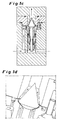
- FIG. 1b provides an enlarged view of the environment of the mixing and reaction zone 10 of the micromixer of FIG. 1a
- the guidance of the two partial flows 6, 7 can be seen particularly clearly here.
- the first partial flow 6 passes from the annular channel 8 via a first entrance slit 19, whose width is determined by the spacer disk 16, in the mixing and reaction zone 10. Due to the uniform thickness of the first entrance slit 19 of the first partial stream 6 flows as a closed film of the Valve body 17 off. Behind this, the first partial flow 6 impinges on the second partial flow 7, which likewise emerges as a closed and uniform film.
- the second partial flow 7 exits from a second inlet gap 20 between the valve tappet 9 and the valve body 17.
- the two partial streams 6, 7 formed as films flow parallel to one another through the mixing and reaction zone 10 to the outlet channel 11. An improvement in the mixing quality is achieved when the spacer disk 16 is microstructured.
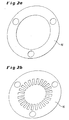
- FIGS. 1a and 1b each give the flow of the FIGS. 1a and 1b again. Reference signs have been omitted.
- the flow curves are each represented by the black arrows.
- Shims 16 are respectively shown, as used to adjust the height of the first entrance gap 19 between the valve body 17 and the middle part 2 for the first partial flow 6.
- the spacer 16 of the FIG. 2b is different from the one in the FIG. 2a in that it additionally has a microstructured configuration in the region of the first entry gap 19 for the first partial flow 6.
- By the spacer disk 16 in the FIG. 2b can be achieved an improvement in the mixing of the two partial streams 6, 7, since the closed film of the first partial stream 6 is decomposed into several individual beams and the speed of these individual beams at the first entrance slit 19 is significantly increased, so that the rays penetrate into the second partial flow 7 and be enclosed by it. In this way, the advantages of microtechnology for the production of small fluid fins are exploited without causing deposits and blockages of the microstructures.
- FIGS. 3a and 3b represent flow patterns in the mixing and reaction zone 10
- FIG. 3a a perspective view of the mixing and reaction zone 10, wherein a spacer disk 16 according to the FIG. 2b has been used.
- the first partial flow 6 is indicated by the black arrows 6, and the second partial flow 7 is represented by white arrows. It can be seen that the first partial flow 6 has been divided into a plurality of individual jets, which are respectively enclosed by the second partial flow 7.
- FIG. 3b is a cross section through the mixing and reaction zone 10 of FIG. 3a reproduced with the corresponding flow path of the first partial flow 6 and the second partial flow 7.
- the FIG. 4 illustrates a valve stem 9 with a structured micro-surface 21.
- the patterned micro-surface 21 is circled and enlarged on the right in a circle. Due to the structured micro-surface 21, the second partial flow 7, which otherwise emerges as a closed fluid film between the valve tappet 9 and the valve body 17 from the second inlet gap 20, is divided into a plurality of individual jets.
- the structures of the structured micro-surface 21 are preferably between 50 and 3000 microns high, and they are placed in the mixing and reaction zone 10 so that the webs connect with the valve stem 9 closed to the wall, so that the second partial flow 7 actually into separate individual jets is split. In this way, a field with very high velocity gradients is generated via the flow cross section of the second partial flow 7 measured. This favors the mixing of the first partial flow 6 with the second partial flow 7.
- FIGS. 5a to 5d each represent a longitudinal section through a micromixer with a check valve as Ragströmsperre.
- Die FIGS. 5a and 5b show a micromixer with a narrow first entrance nip 19.
- the check valve In the FIG. 5a the check valve is closed, and in the FIG. 5b the check valve is open and releases a second entrance slit 20 for the second partial flow 7.
- the FIGS. 5c and 5d represent a micromixer with a wide first entrance slit 19.
- the check valve is closed, and in the FIG. 5d the check valve is open and releases a second entrance slit 20 for the second partial flow 7.
- the first partial flow 6 experiences a much higher speed than in the case of FIG. 5d with a wide first entrance nip 19.
- the width of the first entrance nip 19 and thus also the width of the gap 30, in which the two partial streams 6, 7 converge, and in its extension downstream of the mixing and reaction zone, vary.
- FIG. 6a is a micromixer according to the invention with a membrane body 34 as Ragströmsperre seen in longitudinal section.
- this micromixer also comprises a main body 1, a central part 2 and a lid 3.
- the lid 3 is composed of upper and lower halves, and the middle part 2 is also composed of upper and lower parts.
- the second and the third partial flow 7, 37 are each fed via a non-return valve in the manner of a membrane body 34 to the mixing and reaction zone 10.
- different materials come into question. It can be adjusted by different wall thicknesses of the membrane body 34 and different elasticity of the material to be applied by the differential pressure required opening force. This is similar to the setting in the micromixer FIG.
- the micromixer with membrane body 34 either only a further partial stream or else two further partial streams 7, 37 can be added to your first partial stream 6. It is also conceivable that the first partial flow 6 carries particles with it. The particles can be the. Microstructure penetrate unhindered, since the micromixer has minimum dimensions in the range between 500 and 3,000 microns.
- FIG. 6b is an enlarged view of the FIG. 6a shown in the vicinity of the mixing and reaction zone 10.
- FIGS. 6c and 6d give the flow of the Figures 6a and 6b again. Reference signs have been omitted.
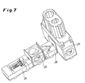
- FIG. 7 a designed as a valve mixer module 24 is shown, which is combined with a further metering point 26 and an electric heating module 27 to form an integrated component. Between the module 24 designed as a valve mixer and the further metering point 26, an insulation module 25 is provided for the thermal decoupling of these adjacent components.
- FIG. 8 represents an advantageous embodiment of the valve mixer with annular coaxial disorder of the entrance column 19, 20, wherein the remindströmsperre is formed in the region of the outer of the two inlet column.
- the return flow lock is realized here by an axially movable valve ring 41 which is sealed by a piston seal 42 relative to the housing 43 and is pressed by an occlusive force 45 against the opposite edge of the entrance slit 19. If the force exerted on the valve ring by the pressure of the first partial flow exceeds the closing force 45, the inlet gap 20 opens and the first partial flow enters the mixing and reaction zone 10.
- FIG. 9 is a further advantageous embodiment of the valve mixer with a ring-shaped coaxial arrangement of the entrance column 19, 20 shown, in which both in the region of the first and the second entrance gap, a return flow lock is formed.
- a return flow lock is formed.
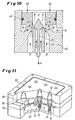
- FIG. 10 shows a likewise advantageous embodiment of the valve mixer, which consists of the in FIG. 9 illustrated embodiment is characterized in that the mixing and reaction zone 10, a third partial flow 37 through a further annular inlet gap 38 which is arranged between the entrance slit for the first 19 and the entrance slit 20 for the second partial flow is supplied.
- FIG. 11 is a parallel arrangement of several inventive valve mixer units in a common housing (51-53) shown with common supply of the partial flows, which can be advantageously used for the mixing of larger volume flows.
- the two supply channels for the first (56) and second partial flow (57) are arranged in this embodiment in two superimposed planes.
- the opening pressure of the check valve is individually variable in order to set a uniform volume flow ratio of the partial flows on all mixer units can.
- the mixture product leaves the individual mixing units in a common outlet channel, which in direct connection above in the FIG. 11 shown assembly is arranged.
Abstract
Description
Die Erfindung betrifft einen Mikromischer zum Vermischen von mindestens zwei unter Bildung von Ausfällungen oder Suspensionen reagierenden Fluiden.The invention relates to a micromixer for mixing at least two fluids which react to form precipitates or suspensions.
Durch den Einsatz mikrostrukturierter Bauteile in Apparaten zur Vermischung von Fluiden werden Vorteile bei der Produktqualität erzielt sowie Mischzeiten und Größe der erforderlichen Apparaturen im Vergleich zu herkömmlichen Aufbauten verringert. Ein wesentliches Merkmal mikrostrukturierter. Bauteile sind die kleinen Abmessungen der Fluidkanäle, die typischerweise im Bereich zwischen 10 und 5.000 µm angesiedelt sind. Aus diesem Grund können beispielsweise mit Multilaminationsmischern feine Fluidlamellen erzeugt werden, zwischen denen aufgrund ihrer geringen Dicke ein schneller Stoffaustausch durch Diffusion erfolgen kann. Die kleinen Abmessungen der durchströmten Querschnitte verlangen allerdings auch besondere Maßnahmen, um sie im Betrieb gegen Ablagerungen und Verstopfungen zu schützen. So werden beispielsweise im Zulauf derartiger Bauteile Partikelfilter eingesetzt, wobei sich die Auswahl der Trenngrenze an den Abmessungen der Mikrostruktur orientiert.The use of microstructured components in fluid mixing apparatus provides product quality advantages as well as reduces mixing time and size of required equipment compared to conventional designs. An essential feature of microstructured. Components are the small dimensions of the fluid channels, which are typically located in the range between 10 and 5,000 microns. For this reason, for example, with multilamination mixers fine fluid fins can be generated, between which due to their small thickness, a rapid mass transfer can occur by diffusion. However, the small dimensions of the flow-through cross sections also require special measures to protect them against deposits and blockages during operation. For example, particulate filters are used in the inflow of such components, the selection of the separation limit being based on the dimensions of the microstructure.
Außer durch Partikel, die über die Zulaufkanäle für die einströmenden Medien in einen Mikromischer gelangen können, besteht auch aufgrund von chemisch-physikalischen Prozessen, die in den Bauteilen etwa nach einer Vermischung ablaufen, die Gefahr von Ablagerungen und Verstopfungen. So können feste Produkte zum Beispiel durch Fällung in Folge einer Neutralisationsreaktion; durch Überschreiten des Löslichkeitsprodukts oder durch Kristallisation des Reaktionsprodukts bei einer Umsetzung organischer oder anorganischer Verbindungen gebildet werden. Aus der
Aufgabe der vorliegenden Erfindung ist es, einen Mikromischer zum Vermischen von mindestens zwei Fluiden zur Verfügung zu stellen, der eine schnelle und effiziente Vermischung der Fluide gewährleistet und gleichzeitig gute Beständigkeit gegenüber unerwünschten. Ablagerungen und Verstopfungen in der Mikrostrukturen aufweist.The object of the present invention is to provide a micromixer for mixing at least two fluids, which ensures fast and efficient mixing of the fluids and at the same time good resistance to undesired ones. Has deposits and blockages in the microstructures.
Die Aufgabe wird überraschenderweise durch den erfindungsgemäßen Mikromischer gelöst.The object is surprisingly achieved by the micromixer according to the invention.
Gegenstand der Erfindung sind daher Mikromischer zum Vermischen von mindestens zwei unter Bildung von Ausfällungen oder Suspensionen reagierenden Fluiden mit den Merkmalen des Anspruchs 1.The invention therefore provides micromixers for mixing at least two fluids which react to form precipitates or suspensions with the features of claim 1.
Der erfindungsgemäße Mikromischer zum Vermischen von mindestens zwei unter Bildung von Ausfällungen oder Suspensionen reagierenden Fluiden weist einen ersten Kanal für die Zufuhr eines ersten Teilstroms und einen zweiten Kanal für die Zufuhr eines zweiten Teilstroms auf. Beide Kanäle münden vorzugsweise in schmalen Eintrittsspalten in eine Misch- und Reaktionszone und verlassen diese über einen Auslasskanal. Zwischen der Misch- und Reaktionszone und mindestens einem Kanal für die Zufuhr, eines Teilstroms ist eine Rückströmsperre angeordnet. Als Vorteil des erfindungsgemäßen Mikromischers erweist es sich, dass in der Misch- und Reaktionszone keine Rückströmungen auftreten. Dadurch werden die damit verbundenen Fällungsreaktionen in den Einlaufbereichen der Misch- und Reaktionszone vermieden. In der Misch- und Reaktionszone erfolg die primäre Keimbildung für die später erfolgenden Ausfällungen und Kristallisationsprozesse. Zur Herstellung fein disperser Feststoffe, wie sie in Ausfällung oder Suspensionen auftreten, müssen hohe Keimbildungsraten erzielt werden. In großtechnischen Prozessen werde daher in entsprechenden Misch- und Reaktionszonen hohe Schergeschwindigkeiten durch schnelle Strömungen oder intensives Rühren realisiert. Hohe Keimbildungsraten mit Hilfe mikrostrukturierter Bauteile lassen sich erzielen, wenn feine Fluidstrahlen in ein strömendes Fluid injiziert werden. Die zugeführten Fluide können selbst bereits partikelhaltig sein.The micromixer according to the invention for mixing at least two fluids reacting to form precipitates or suspensions has a first channel for the supply of a first partial flow and a second channel for the supply of a second partial flow. Both channels preferably open into narrow inlet gaps in a mixing and reaction zone and leave them via an outlet channel. Between the mixing and reaction zone and at least one channel for the supply of a partial flow, a backflow preventer is arranged. As an advantage of the micromixer according to the invention, it turns out that no backflows occur in the mixing and reaction zone. As a result, the associated precipitation reactions in the inlet areas of the mixing and reaction zone are avoided. In the mixing and reaction zone, the primary nucleation succeeds for the later precipitations and crystallization processes. For the production of finely dispersed solids, as they occur in precipitation or suspensions, high nucleation rates must be achieved. In large-scale processes, therefore, high shear rates are achieved by rapid flows or intensive stirring in corresponding mixing and reaction zones. High nucleation rates with the aid of microstructured components can be achieved when fine fluid jets are injected into a flowing fluid. The supplied fluids themselves may already be particle-containing.
Vorteilhafte Ausführungsformen des Mikromischers sind Gegenstand der Unteransprüche.Advantageous embodiments of the micromixer are the subject of the dependent claims.
Ein gleichmäßiges Wachstum gebildeter Keime zu einheitlicher Partikelgröße setzt voraus, dass sich der Misch- und Reaktionszone ein gleichförmiges Strömungsfeld mit niedrigen Geschwindigkeiten abschließt. Dies wird mit Vorteil realisiert durch einen Auslasskanal mit einer glatten und sich aufweitenden Geometrie.Uniform growth of nucleated seeds into uniform particle size requires that the mixing and reaction zone complete a uniform flow field at low velocities. This is realized with advantage by an outlet channel with a smooth and widening geometry.
Die Rückströmsperre des Mikromischers ist vorzugsweise als Rückschlagventil oder als Membrananordnung ausgebildet. Die Vorspannung der Feder des Rückschlagventils kann mit Hilfe von mechanischen Mitteln eingestellt werden. In einer besonders vorteilhaften Ausführung kann die Federvorspannung und/oder die Federkonstante und damit der Ansprechdruck bzw. das Öffnungsverhalten des Rückschlagventils während des Betriebs des Mischers von außen eingestellt werden. Insbesondere bei einer Einbindung des Rückschlagventils in einen externen Regelkreis erweist sich die Verwendung eines elektrischen, pneumatischen, hydraulischen oder elektromagnetischen Antriebs für das Rückschlagventil als vorteilhaft.The backflow barrier of the micromixer is preferably designed as a check valve or as a membrane arrangement. The bias of the spring of the check valve can be adjusted by mechanical means. In a particularly advantageous embodiment, the spring preload and / or the spring constant and thus the set pressure or the opening behavior of the check valve during operation of the mixer can be adjusted from the outside. In particular, in an integration of the check valve in an external control loop, the use of an electric, pneumatic, hydraulic or electromagnetic drive proves to be advantageous for the check valve.
In einer weiteren vorteilhaften Ausführungsform des Mischers, kann die Breite wenigstens eines der Eintrittsspalte und/oder die charakteristische Dimension der Misch- und Reaktionszone während des Betriebs des Mischers kontinuierlich oder stufenweise eingestellt werden. Die Einstellung dieser Größen kann dabei durch mechanischen, pneumatischen, hydraulischen, piezoelektrischen, elektrostatischen oder elektromagnetischen Antrieb erfolgen. In einer besonders vorteilhaften Ausführung des Mischers können diese Größen darüber hinaus als Stellgrößen in einen Regelkreis eingebunden werden.In a further advantageous embodiment of the mixer, the width of at least one of the inlet column and / or the characteristic dimension of the mixing and reaction zone during operation of the mixer can be adjusted continuously or stepwise. The adjustment of these sizes can be achieved by mechanical, pneumatic, hydraulic, piezoelectric, electrostatic or electromagnetic drive. In a particularly advantageous embodiment of the mixer, these variables can also be incorporated as manipulated variables in a control loop.
Als Regelgrößen für die Einstellung des Ansprechdrucks bzw. Öffnungsverhaltens des Rückschlagventils, der Breite wenigstens einer der Eintrittsspalte und/oder der charakteristischen Dimension der Misch- und Reaktionszone werden bevorzugt chemische oder physikalische Eigenschaften des Misch- bzw. Reaktionsprodukts, insbesondere solche, die sich durch eine schnelle online-Messung ermitteln lassen, wie z.B. Temperatur, Farbe, Lichtstreu- oder Absorptionsverhalten, pH-Wert oder elektrische Leitfähigkeit, herangezogen.As controlled variables for the setting of the response pressure or opening behavior of the check valve, the width of at least one of the inlet gaps and / or the characteristic dimension of the mixing and reaction zone, preference is given to chemical or physical properties of the mixing or reaction product, in particular those which are distinguished by a determine fast online measurement, such as Temperature, color, light scattering or absorption behavior, pH or electrical conductivity, used.
Die Eintrittsspalte für die verschiedenen Teilströme können linear - dann vorzugsweise parallele oder radial, oder gekrümmt - dann vorzugsweise ringförmig konzentrisch oder axial in Folge - angeordnet sein. Linear angeordnete Eintrittsspalte eignen sich in besonders vorteilhafter Weise, um erfindungsgemäße Mikromischer für hohe Volumenströme; z.B. oberhalb einiger 100 L/h zu realisieren. Im Fall einer ebenfalls vorteilhaften ringförmigen konzentrischen Anordnung kann die Rückströmsperre sowohl Bestandteil des inneren und/oder des äußeren Kanals sein. Für den Fall, dass das Rückschlagventil Bestandteils des inneren Kanals ist, ist die Funktionsweise des Mischers in den
In einer weiteren bevorzugten Ausführungsform der Erfindung besteht der Mikromischer aus mindestens einem innen liegenden als auch einem außen liegenden Rückschlagventil, siehe
Die in die Misch- und Reaktionszone zulaufenden Teilströme können in vielfältiger Weise durch eine entsprechende Gestaltung der Strömungsführung aufgefächert werden, wodurch die Mischgeschwindigkeit und damit die Keimbildungsrate erhöht wird. In einer bevorzugten Ausführungsform der Erfindung, wie sie in den
In einer weiteren vorteilhaften Ausführung des erfindungsgemäßen Mikromischers ist die Rückstromsperre elektrisch, pneumatisch, hydraulisch oder elektromagnetisch ansteuerbar. Besonders vorteilhaft ist dabei eine Ausführung, bei der die Rückstromsperre durch einen äußeren Erreger mit hoher Frequenz periodisch bewegt werden kann. Besonders bevorzugt ist hier Ausführung als Rückschlagventil mit einem leichten Ventilteller und periodischer Erregung durch einen Piezoschwinger oder Elektromagneten. Als Erregerfrequenzen sind hierbei Frequenzen im Mega-Hertz-Bereich besonders bevorzugt.In a further advantageous embodiment of the micromixer according to the invention, the non-return valve can be controlled electrically, pneumatically, hydraulically or electromagnetically. Particularly advantageous is an embodiment in which the backflow lock can be moved periodically by an external exciter with high frequency. Particularly preferred here is execution as a check valve with a slight valve disk and periodic excitation by a piezoelectric oscillator or electromagnet. Frequencies in the megahertz range are particularly preferred as exciter frequencies.
Für den Einsatz des erfindungsgemäßen Mischers bei hohen Volumendurchsätzen der eingehenden Teilströme ist bevorzugt eine Mischereinheit bestehend aus mehreren parallel betriebenen identischen Anordnungen von Eintrittsspalten mit jeweils separaten Rückstromsperren und Mischzonen in einem gemeinsamen Gehäuse und mit gemeinsamer Fluidzuführung einzusetzen, wobei die Fluidzuführung zu den einzelnen Anordnungen bevorzugt derart gestaltet und die Öffnungsdrücke der einzelnen Rückstromsperren, derart aufeinander abgestimmt sind, dass in allen Mischzonen der Mischereinheit im Betrieb dieselben Mischungs- und Strömungsverhältnisse herrschen.For use of the mixer according to the invention at high volumetric throughputs of the incoming substreams, it is preferable to use a mixer unit consisting of several identical arrangements of entry slits operated in parallel, each with separate backflow locks and mixing zones in a common housing and with common fluid supply, the fluid supply to the individual arrangements preferably being such designed and the opening pressures of the individual return flow, are coordinated with each other so that prevail in all mixing zones of the mixer unit in operation the same mixing and flow conditions.
Die erfindungsgemäßen Mikromischer werden bevorzugt durch Verfahren der Feinwerktechnik und Mikrofertigungstechnik hergestellt. Dies umfasst alle gängigen Methoden, wie z.B. die spanabhebende Bearbeitung, Funkenerosion oder Materialbearbeitung mit Laserstrahlung. Wird ein Rückschlagventil als Rückströmsperre eingesetzt, so wird dessen Dichtwirkung in vorteilhafter Weise durch Ausstattung mit einer Elastomerdichtung erreicht. In einer anderen vorteilhaften Ausführung wird die Dichtwirkung des Rückschlagventils durch Einschleifen des Ventilkonus in seinen Sitz erreicht. Diese Form der Dichtung eignet sich in besonders vorteilhafter Weise, wenn der Mischer bei hohen Temperaturen eingesetzt werden soll.The micromixers according to the invention are preferably produced by processes of precision engineering and microfabrication technology. This includes all common methods, e.g. the machining, spark erosion or material processing with laser radiation. If a check valve is used as a non-return valve, then its sealing effect is achieved in an advantageous manner by equipping with an elastomeric seal. In another advantageous embodiment, the sealing effect of the check valve is achieved by grinding the valve cone into its seat. This form of seal is particularly advantageous if the mixer is to be used at high temperatures.
Die Mikromischer können dabei vorteilhaft aus den in der Verfahrenstechnik gängigen Materialien wie Edelstählen, Nickelbasis-Legierungen, Titan. oder Tantal gefertigt werden. Insbesondere bei Einsatz der Mikromischer unter hohen Temperaturen oder mit korrosiven Medien sind jedoch auch bevorzugt keramische Materialien wie z.B. Aluminiumoxid, Zirkonoxid, Siliziumnitrid, Aluminiumnitrid oder Siliziumcarbid einzusetzen.The micromixers can advantageously be made of the materials commonly used in process engineering, such as stainless steels, nickel-base alloys, titanium. or tantalum are made. However, especially when using the micromixers under high temperatures or with corrosive media, ceramic materials such as e.g. Alumina, zirconia, silicon nitride, aluminum nitride or silicon carbide use.
Die erfindungsgemäßen Mikroreaktoren werden dabei bevorzugt für Kristallisations- und Fällungsreaktionen eingesetzt.The microreactors according to the invention are preferably used for crystallization and precipitation reactions.
Wenn in den Mikromischer Substanzen eindringen, die spontan kristallisieren, ist es sinnvoll, die Rückströmsperren mit Reinigungsstiften zu versehen, die vorzugsweise eine nadelförmige Spitze aufweisen. Die Reinigungsstifte befreien die Mikrostrukturen bei jedem Öffnungs- und Schließvorgang von etwaigen Ablagerungen. Die Reinigungsstifte können entweder entgegen der Strömungsrichtung in eine betreffende Austrittsöffnung eingeführt werden oder in Strömungsrichtung. Werden etwaige Ablagerungen durch die Reinigungsstifte in Strömungsrichtung herausgedrückt, so erweist sich das als besonders vorteilhaft. Die Mikrostrukturen können auch durch kurzzeitiges Betätigen der Rückströmsperren im laufenden Betrieb mit Hilfe der Reinigungsstifte von Ablagerungen befreit werden. Der Betrieb muss dafür nicht unterbrochen werden. Das kurzzeitige Schließen zu Reinigungszwecken kann manuell, über gezielt aufgebrachte Druckschwankungen oder über einen externen Regelkreis ausgelöst werden.If substances that spontaneously crystallize penetrate into the micromixer, it is expedient to provide the non-return valves with cleaning pins, which preferably have a needle-shaped tip. The cleaning pins free the microstructures during each opening and closing operation from any deposits. The cleaning pins can either be introduced counter to the flow direction into a respective outlet opening or in the flow direction. If any deposits are pushed out by the cleaning pins in the flow direction, this proves to be particularly advantageous. The microstructures can also be freed from deposits by briefly actuating the non-return valves during operation with the aid of the cleaning pins. The operation does not have to be interrupted for this. Short-term closing for cleaning purposes can be triggered manually, via specifically applied pressure fluctuations or via an external control circuit.
Die Zuführung der Teilströme in einen kreis- oder ringförmigen Querschnitt kann unter hohem Druck und aus feinen Düsen erfolgen. Da Kristallisationsprozesse in verschiedenen Phasen ablaufen, die durch die Schergradienten beeinflusst werden, ist das Aufeinandertreffen der Teilströme unter verschiedenen Winkeln vorteilhaft, um unterschiedliche Geschwindigkeitsgradienten zwischen den Teilströmen zu realisieren. Die Teilströme treffen bevorzugt in einem Winkel zwischen 5 und 175° aufeinander. Treffen die Teilströme in spitzen Winkeln aufeinander, so weist eine Hauptkomponente ihre Bewegung in Ausströmrichtung, so dass sich die Relativgeschwindigkeiten der einzelnen Teilströme langsam angleichen. Auf diese Weise können am Einspritzpunkt hohe Schergradienten realisiert werden, um die Keimbildung zu begünstigen. Die nachfolgende Abnahme der Relativgeschwindigkeiten wirkt sich günstig auf das Kristallwachstum aus. Bei einer Einspritzung eines Teilstroms im rechten Winkel können höhere Geschwindigkeitsgradienten in der Nähe der Dosierstelle realisiert werden, woraus eine hohe Keimbildungsrate resultiert. Anschließend kann ein erster Teilstrom durch einen zweiten Teilstrom in Ausströmrichtung bewegt werden, wobei sich die Relativgeschwindigkeit zwischen den Teilströmen verringert. Die Keimbildungsrate lässt sich weiter steigern, wenn die Einspritzung unter einem stumpfen Winkel erfolgt, beilspielsweise 175°. In diesem Fall treten die größten Geschwindigkeitsgradienten an der Einspritzstelle auf.The supply of the partial streams in a circular or annular cross-section can be carried out under high pressure and from fine nozzles. Since crystallization processes take place in different phases, which are influenced by the shear gradients, the meeting of the partial flows at different angles is advantageous in order to realize different velocity gradients between the partial flows. The partial flows preferably meet at an angle of between 5 and 175 °. If the partial flows meet at acute angles, then a main component has its movement in the outflow direction, so that the relative speeds of the individual partial flows slowly converge. In this way, high shear gradients can be realized at the injection point to promote nucleation. The subsequent decrease in relative velocities has a favorable effect on crystal growth. When injecting a partial flow at right angles higher velocity gradients can be realized in the vicinity of the metering, resulting in a high nucleation rate. Subsequently, a first partial flow can be moved through a second partial flow in the outflow direction, wherein the relative velocity between the partial flows is reduced. The nucleation rate can be further increased if the injection is at an obtuse angle, for example 175 °. In this case, the largest velocity gradients occur at the injection site.
Kristallisations- und Fällungsprodukte bedürfen in vielen Fällen einer weiteren Behandlung, um beispielsweise den pH-Wert im Produktstrom durch Nachdosierung einer Säure oder einer Lauge zu regeln oder mit Hilfe von Inhibitoren oder Stabilisatoren die Kristallgröße zu steuern. Oft sind dafür weitere Dosierstellen erforderlich. Diese können in einem oder in mehreren hintereinander geschalteten Apparaturen realisiert werden. In diesem Zusammenhang kann es auch notwendig sein, die zuströmenden Medien, ein gesamtes Bauteil, die Misch- und Reaktionszone oder weitere sich anschließende Bauteile gezielt zu temperieren.In many cases, crystallization and precipitation products require further treatment in order, for example, to control the pH in the product stream by subsequent addition of an acid or a lye or to control the crystal size with the aid of inhibitors or stabilizers. Often, this requires additional dosing points. These can be realized in one or more devices connected in series. In this context, it may also be necessary to specifically temper the inflowing media, an entire component, the mixing and reaction zone or other adjoining components.
Eine Beeinflussung der Partikelgröße der gebildeten Kristallisations- oder Fällungsprodukte kann erfolgen, indem der Querschnitt des Auslasskanals regelmäßig oder unregelmäßig gestaltet wird. Aufgrund ihrer gegenüber dem Medium unterschiedlichen Dichte bewegen sich die Fällungsprodukte meist mit geringerer Geschwindigkeit als die strömende Flüssigkeit. An einer Engstelle kommt es zu einer Beschleunigung der Strömung, an einer Erweiterung zu einer Beruhigung der Strömung. Auf diese Weise können gezielt Geschwindigkeitsgradienten aufgeprägt werden, die eine Zerschlagung großer Aggregate oder deren Vergrößerung bewirken.An influence on the particle size of the formed crystallization or precipitation products can take place by the cross section of the outlet channel is made regular or irregular. Due to their different density from the medium, the precipitation products move usually at a lower speed than the flowing liquid. At a bottleneck there is an acceleration of the flow, at an extension to a calming of the flow. In this way, targeted speed gradients can be impressed, which cause a breakdown of large aggregates or their enlargement.
Fällungs- und Kristallisationsprodukte neigen in Abhängigkeit von ihren Eigenschaften, der Wandrauhigkeit und den Strömungsbedingungen zur Ablagerung an den Wandungen des Mikromischers. Es erweist sich daher als günstig, die ausströmenden Produkte im Auslasskanal in einen Mantelstrahl einzuschließen, der zwischen der Wandung des Auslasskanals und dem ausströmenden Produkt als geschlossener Film zugeleitet wird.Precipitation and crystallization products tend to deposit on the walls of the micromixer depending on their properties, wall roughness and flow conditions. It therefore proves to be beneficial to include the effluent products in the outlet channel in a jacketed jet which is fed between the wall of the outlet channel and the effluent product as a closed film.
In einer anderen vorteilhaften Ausführungsform des Mikromischers ist dieser im Bereich des Auslasskanals aus einem gegen Anhaftungen besonders resistenten Material, wie z.B. PTFE, gefertigt, die Wandung des Auslasskanals ist mit einem solchen Material beschichtet und/oder die Oberfläche dieser Wandung ist ,z.B. durch Einsatz eines Politur oder Elektropoliturverfahrens; besonders glatt ausgeführt.In another advantageous embodiment of the micromixer, this is in the region of the outlet channel of a particularly resistant to adhesion material, such. PTFE, made, the wall of the outlet channel is coated with such a material and / or the surface of this wall is, for. by using a polish or electropolishing process; very smooth.
Bei der Erzeugung von Partikeln oder Nanopartikeln ist vorzugsweise wenigstens einer der dem Mischer zugeführten Teilströme eine Flüssigkeit, Gas, ein kondensiertes Gas, ein überkritisches Lösungsmittel, ein Nebel, ein Gas mit festen, gegebenenfalls katalytisch aktiven Bestandteilen oder eine Emulsion, oder ein sich infolge der in der Mischzone stattfindenden Prozesse im Mischer bildendes Medium.In the production of particles or nanoparticles is preferably at least one of the streams supplied to the mixer, a liquid, gas, a condensed gas, a supercritical solvent, a mist, a gas with solid, optionally catalytically active ingredients or an emulsion, or due to the occurring in the mixing zone processes in the mixer forming medium.
Bei den Fällungsreaktionen kann die Reaktion beispielsweise durch die Zufuhr eines weiteren Stroms unterbrochen werden oder es können weitere Schichten anderer Feststoffe auf die durch Fällung erzeugten Partikel aufgebracht werden. Auf diese Weise eignet sich der Mischer u.a. vorteilhaft zur Erzeugung von Partikeln bzw. Nanopartikeln mit mehreren, in konzentrischer Abfolge angeordneten' Schichten aus unterschiedlichen Substanzen. Zur Beeinflussung der Teilchengröße sowie zwecks Überführung der erzeugten Partikel in eine andere fluide Phase können ferner oberflächenaktive Substanzen zum Produktstrom zugeführt werden.In the precipitation reactions, for example, the reaction may be interrupted by the introduction of another stream, or further layers of other solids may be applied to the particles produced by precipitation. In this way, the mixer u.a. advantageous for the production of particles or nanoparticles with a plurality of 'arranged in concentric sequence' layers of different substances. In order to influence the particle size and in order to transfer the particles produced into another fluid phase, surface-active substances can furthermore be supplied to the product stream.
Der erfindungsgemäße Mischer ermöglicht zudem die Herstellung von Nanopartikeln in der Gasphase, wobei wenigstens einer der zugeführten Teilströme bereits fein verteilte Partikel wie z.B. Nanopartikel mit katalytischer Wirkung enthalten kann. Auf diese Weise kann der Mischer z.B. vorteilhaft zur Vermischung von mit katalytisch aktiven Nanopartikeln versetzten gasförmigen Kohlenwasserstoffen und Ammoniakgas verwendet werden, um durch chemische Umsetzung des so erzeugten Gemischs Kohlenstoff-Nanoröhrehen zu erzeugen.The mixer according to the invention also allows the production of nanoparticles in the gas phase, wherein at least one of the supplied partial streams may already contain finely divided particles such as nanoparticles with catalytic activity. In this way, for example, the mixer can advantageously be used for mixing gaseous hydrocarbons mixed with catalytically active nanoparticles and ammonia gas in order to produce carbon nanotubes by chemical reaction of the mixture thus produced.
Ferner ist mit dem Mischer vorteilhaft die In-Situ-Herstellung von Emulsionen möglich, welche somit auch dann für die Durchführung von Fällungs- und Kristallisationsreaktionen sowie für die Herstellung von Nanopartikeln genutzt werden können, wenn sie sehr instabil sind.Furthermore, it is advantageously possible with the mixer to prepare in-situ emulsions, which can thus also be used for carrying out precipitation and crystallization reactions as well as for the production of nanoparticles if they are very unstable.
Eine weitere vorteilhafte Verwendung des Mischers besteht in der Fällung bzw. Kristallisation von Partikeln unter Verwendung überkritischer Lösungsmittel sowie hoch komprimierter oder kondensierter Gase, da der Mikromischer in besonders vorteilhafter Weise das Arbeiten bei hohen Drücken ermöglicht. Im Falle einer solchen Verwendung kann das Mischungsprodukt stromabwärts hinter dem Mischer auf vorteilhafte Weise durch adiabatische Entspannung des Trägermediums abgekühlt werden. Eine solche Abkühlung kann sehr schnell erfolgen und damit in vorteilhafter Weise eine schnelle Keimbildung einleiten oder aber sehr kurz nach dem Einsetzen des Partikelwachstums die chemische Reaktion bzw. ein weiteres Partikelwachstum stoppen.A further advantageous use of the mixer is the precipitation or crystallization of particles using supercritical solvents and highly compressed or condensed gases, since the micromixer makes it possible in a particularly advantageous manner to work at high pressures. In the case of such use, the product of the mixture downstream of the mixer may advantageously be cooled by adiabatic relaxation of the carrier medium. Such cooling can take place very quickly and thus advantageously initiate rapid nucleation or stop the chemical reaction or further particle growth very shortly after the onset of particle growth.
Diese Verwendungen sind ebenfalls Gegenstand der Erfindung.These uses are also the subject of the invention.
Für komplexere, z.B. mehrstufige Reaktionen kann der erfindungsgemäße Mischer auch mit weiteren Bauelementen kombiniert werden, die zum Aufbau eines Mikroreaktionssystems notwendig sind, wie z.B. Wärmetauscher, elektrische Heizmodule (27), thermische Isolatoren (25), weitere durchströmbare Dosierstellen (26) bzw. Mischer, wie z.B. Mantelstrommischer, Steuerungseinheiten etc. sowie Messeinrichtungen, z.B. zur Ermittlung von Temperaturen, Druck, pH-Wert, elektrischen oder optischen Eigenschaften der durchströmenden Substanzen. Insbesondere Stromabwärts des Mikromischers sind dabei bevorzugt solche Komponenten einzusetzen, die nicht durch die im Mischer erzeugten Partikel verstopfen oder sonst in ihrer Funktion beeinträchtigt werden und/oder sich mit geringem Aufwand demontieren und reinigen lassen.For more complex, e.g. Multi-stage reactions, the mixer according to the invention can also be combined with other components that are necessary for the construction of a microreaction system, such. Heat exchangers, electric heating modules (27), thermal insulators (25), further metered-through metering points (26) or mixers, such. Domestic mixers, control units etc. as well as measuring devices, e.g. for the determination of temperatures, pressure, pH, electrical or optical properties of the substances flowing through. In particular downstream of the micromixer are preferably to use those components that are not clogged by the particles generated in the mixer or otherwise impaired in their function and / or can be disassembled and cleaned with little effort.
Stromabwärts hinter dem Mischer angeordnete Dosierstellen können auch zur Temperierung des Produktstroms eingesetzt werden, indem sie diesem ein geeignet temperiertes Fluid zuführen.Downstream of the mixer arranged metering can also be used to control the temperature of the product stream by supplying this a suitably tempered fluid.
Der erfindungsgemäße Mikromischer wird anhand der folgenden Figuren beispielhaft erläutert.The micromixer according to the invention will be explained by way of example with reference to the following figures.
Es zeigen:
- Figur 1a
- einen erfindungsgemäßen Mikromischer, insbesondere einen Ventilmischer, mit Rückschlagventil im Längsschnitt,
- Figur 1b
- eine vergrößerte Ansicht des Mikromischers der
Figur 1a auf die Umgebung der Misch- und Reaktionszone, - Figur 1c
- die Strömungsverläufe im Mikromischer aus
Figur 1a , - Figur 1d
- die Strömungsverläufe in der vergrößerten Ansicht der
Figur 1b , - Figur 2a
- eine Abstandsscheibe zur Einstellung der Höhe des Eintrittsspalts für den ersten Teilstrom,
- Figur 2b
- eine Abstandsscheibe mit mikrostrukturierter Ausgestaltung,
- Figur 3a
- eine perspektivische Ansicht auf die Misch- und Reaktionszone des Mikromischers mit Rückschlagventil,
- Figur 3b
- einen Querschnitt durch die Misch- und Reaktionszone der
Figur 3a , Figur 4- einen Längsschnitt durch einen Ventilstößel mit mikrostrukturierter. Ausgestaltung der Oberfläche mit einer vergrößerten Ansicht in Wandnähe,
- Figur 5a
- einen Längsschnitt durch einen Ventilmischer mit schmalem ersten Eintrittsspalt und geschlossenem Rückschlagventil,
- Figur 5b
- einen Längsschnitt durch den Ventilmischer aus
Figur 5 a mit geöffnetem Rückschlagventil, - Figur 5c
- einen Längsschnitt durch einen Ventilmischer mit breitem ersten Eintrittsspalt und geschlossenem Rückschlagventil,
- Figur 5d
- einen Längsschnitt durch den Ventilmischer aus
Figur 5c mit geöffnetem Rückschlagventil, - Figur 6a
- einen erfindungsgemäßen Mikromischer mit Membrananordnung im Längsschnitt,
- Figur 6b
- eine vergrößerte Ansicht des Mikromischers der
Figur 6a im Umgebungsbereich der Misch- und Reaktionszone, - Figur 6c
- die Strömungsverläufe im Mikromischer der
Figur 6b , - Figur 6d
- die Strömungsverläufe in der vergrößerten Ansicht der
Figur 6b , Figur 7- einen erfindungsgemäßen Ventilmischer in Kombination mit einer weiteren Dosierstelle und einem beheizten Auslasskanal.
Figur 8- einen Ventilmischer mit einem außen liegenden Rückschlagventil
Figur 9- einen Ventilmischer mit einem außen liegenden und einem innen liegenden Rückschlagventil
Figur 10- einen Ventilmischer mit einem innen liegenden und einem außen liegenden Rückschlagventil, welcher einen zusätzlichen Strömungskanal und Eintrittsspalt zur Zuführung eines weiteren Teilstroms ausgebildet hat.
Figur 11- einen Ventilmischer für große Volumenströme, der als parallele Anordnung mehrerer identischer Ventilmischereinheiten in einem gemeinsamen Gehäuse mit gemeinsamer Zuführung der Teilströme sowie gemeinsamen, Abführung des Mischungsprodukts ausgebildet ist.
- FIG. 1a
- a micromixer according to the invention, in particular a valve mixer, with a check valve in longitudinal section,
- FIG. 1b
- an enlarged view of the micromixer of
FIG. 1a to the environment of the mixing and reaction zone, - Figure 1c
- the flow patterns in the micromixer
FIG. 1a . - Figure 1d
- the flow patterns in the enlarged view of
FIG. 1b . - FIG. 2a
- a spacer plate for adjusting the height of the entrance gap for the first partial flow,
- FIG. 2b
- a spacer disk with a microstructured design,
- FIG. 3a
- a perspective view of the mixing and reaction zone of the micromixer with check valve,
- FIG. 3b
- a cross section through the mixing and reaction zone of
FIG. 3a . - FIG. 4
- a longitudinal section through a valve stem with microstructured. Design of the surface with an enlarged view near the wall,
- FIG. 5a
- a longitudinal section through a valve mixer with narrow first entrance gap and closed check valve,
- FIG. 5b
- a longitudinal section through the valve mixer
FIG. 5 a with open check valve, - FIG. 5c
- a longitudinal section through a valve mixer with a wide first entrance gap and closed check valve,
- FIG. 5d
- a longitudinal section through the valve mixer
FIG. 5c with open check valve, - FIG. 6a
- a micromixer according to the invention with membrane arrangement in longitudinal section,
- FIG. 6b
- an enlarged view of the micromixer of
FIG. 6a in the surrounding area of the mixing and reaction zone, - FIG. 6c
- the flow patterns in the micromixer the
FIG. 6b . - FIG. 6d
- the flow patterns in the enlarged view of
FIG. 6b . - FIG. 7
- a valve mixer according to the invention in combination with a further metering point and a heated outlet channel.
- FIG. 8
- a valve mixer with an external check valve
- FIG. 9
- a valve mixer with an external and an internal check valve
- FIG. 10
- a valve mixer having an inner and an outer non-return valve, which has formed an additional flow channel and entrance slit for supplying a further partial flow.
- FIG. 11
- a large volume flow valve mixer, which is designed as a parallel arrangement of a plurality of identical valve mixing units in a common housing with a common supply of the partial flows and common, discharge of the mixture product.
In der
Die
Die
In den
Die
Die
Die
In der
In der
Die
In der
In
In
- 11
- Grundkörperbody
- 22
- Mittelteilmidsection
- 33
- Deckelcover
- 44
- erster O-Ringfirst O-ring
- 55
- zweiter O-Ringsecond O-ring
- 66
- erster Teilstromfirst partial flow
- 7.7th
- zweiter Teilstromsecond partial flow
- 88th
- Ringkanal für den ersten TeilstromsRing channel for the first partial flow
- 99
- Ventilstößeltappet
- 1010
- Misch-und ReaktionszoneMixing and reaction zone
- 1111
- Auslasskanalexhaust port
- 1212
- Bohrungen im Ventilkörper für den zweiten TeilstromHoles in the valve body for the second partial flow
- 1313
- Spiralfederspiral spring
- 1414
- Muttermother
- 1515
- Kontermutterlocknut
- 1616
- Abstandsscheibespacer
- 1717
- Ventilkörpervalve body
- 18 :18:
- dritter Ö-Ringthird Ö-ring
- 1919
- Eintrittsspalt für den ersten TeilstromEntrance gap for the first partial flow
- 2020
- Eintrittsspalt für den zweiten TeilstromEntrance gap for the second partial flow
- 2121
- mikrostrukturierte Oberfläche des Ventilstößelmicrostructured surface of the valve lifter
- 2424
- als Ventilmischer ausgebildetes Moduldesigned as a valve mixer module
- 2525
- Isolationsmodul zur thermischen Entkopplung benachbarter BauteileInsulation module for thermal decoupling of adjacent components
- 2626
- weitere Dosierstellefurther dosing point
- 2727
- elektrisches Heizmodulelectric heating module
- 3030
- Abstanddistance
- 3434
- Membrankörpermembrane body
- 3737
- dritter Teilstromthird partial flow
- 3838
- Eintrittsspalt für dritten TeilstromEntry slit for third partial flow
- 4040
- Zentraler KonusCentral cone
- 4141
- Ventilringvalve ring
- 4242
- Kolbendichtungpiston seal
- 4343
- Gehäusecasing
- 4545
- verschließende Kraftwirkung auf Ventilringclosing force on valve ring
- 4646
- verschließende Kraftwirkung auf Ventilstößelclosing force on the valve lifter
- 5151
- gemeinsamer Grundkörpercommon body
- 5252
- gemeinsamer Mittelteilcommon middle part
- 5353
- gemeinsame Auslassplattecommon outlet plate
- 5656
- gemeinsamer Versorgungskanal für ersten Teilstromcommon supply channel for the first partial flow
- 5757
- gemeinsamer Versorgungskanal für zweiten Teilstromcommon supply channel for second partial flow
Claims (13)
- Micromixer for mixing at least two fluids which react to form precipitates or suspensions, having a first channel for supplying a first sub-flow (6) and having a second channel for supplying a second sub-flow (7), which open in flat entry gaps (19, 20) into a mixing and reaction zone (10) and leave the mixing and reaction zone (10) via an outlet channel (11), a reflux barrier being arranged between the mixing and reaction zone (10) and at least one channel for supplying a sub-flow (6, 7, 37), characterized in that the element which defines the prestress of the reflux barrier is arranged in the flow direction in front of the entry of the sub-flow (6, 7, 37) which flows past the reflux barrier into the mixing and reaction zone (10).
- Micromixer according to Claim 1, characterized in that the reflux barrier is designed as a non-return valve.
- Micromixer according to Claim 2, characterized in that the prestress of the non-return valve is provided by mechanical means (13, 14, 15).
- Micromixer according to Claim 2, characterized in that the non-return valve is electrically, pneumatically, hydraulically or electromagnetically drivable.
- Micromixer according to one or more of Claims 1 to 4, characterized in that the non-return valve is designed as a membrane arrangement.
- Micromixer according to one or more of Claims 1 to 5, characterized in that deposits are cleaned from the reflux barrier in the course of operation by cleaning pins, which insert into the opening uncovered by the reflux barrier during each opening and closing process and are essentially designed with a needle shape.
- Micromixer according to one or more of Claims 1 to 6, characterized in that entry gaps (19, 20) for the sub-flows (6, 7, 37) are designed as narrow annular gaps, so that the sub-flows (6, 7, 37) meet each other as thin film layers.
- Micromixer according to one or more of Claims 1 to 7, characterized in that the entry gaps (19, 20) are bounded by microstructured components (16, 9), which contribute to dividing the sub-flows (6, 7, 37) into individual sub-streams.
- Micromixer one or more of Claims 1 to 8, characterized in that the outlet channel (11) has a smooth and widening geometry.
- Micromixer one or more of Claims 1 to 9, characterized in that a feed for an envelope stream, which encloses the mixed sub-flows (6, 7, 37) when they emerge, is provided in the outlet channel (11).
- Micromixer one or more of Claims 1 to 10, characterized in that the response pressure and/or the opening behaviour of the reflux barrier, the width of characteristic dimensions of the mixing and reaction characteristic dimensions of the mixing and reaction zone (10) are externally adjustable by mechanical, hydraulic, pneumatic, electrical or electromagnetic means and/or are automatically varied as control variables of an outer or inner control loop.
- Micromixer one or more of Claims 1 to 11, characterized in that two or more valve mixer units according to the invention are arranged in a common housing with common supplies of the sub-flows (6, 7, 37) and a common outlet channel (11), so that they can be operated in parallel.
- Use of the micromixer according to one or more of Claims 1 to 12 for precipitation and/or crystallization reactions, the preparation of nanoparticles, carbon nanotubes, fullerenes or particles/nanoparticles having a plurality of layers of different substances arranged in a concentric sequence.
Priority Applications (1)
| Application Number | Priority Date | Filing Date | Title |
|---|---|---|---|
| EP05707247A EP1718402B1 (en) | 2004-02-17 | 2005-02-08 | Micromixer |
Applications Claiming Priority (4)
| Application Number | Priority Date | Filing Date | Title |
|---|---|---|---|
| EP04003471A EP1666132A1 (en) | 2004-02-17 | 2004-02-17 | Micromixer |
| DE102005003965A DE102005003965A1 (en) | 2005-01-27 | 2005-01-27 | Micro-mixer for precipitation and/or crystallization reactions comprises reverse flow prevention unit placed between mixing and reaction zone and at least one channel for introducing partial stream |
| EP05707247A EP1718402B1 (en) | 2004-02-17 | 2005-02-08 | Micromixer |
| PCT/EP2005/001227 WO2005079964A1 (en) | 2004-02-17 | 2005-02-08 | Micromixer |
Publications (2)
| Publication Number | Publication Date |
|---|---|
| EP1718402A1 EP1718402A1 (en) | 2006-11-08 |
| EP1718402B1 true EP1718402B1 (en) | 2008-08-13 |
Family
ID=34888843
Family Applications (1)
| Application Number | Title | Priority Date | Filing Date |
|---|---|---|---|
| EP05707247A Active EP1718402B1 (en) | 2004-02-17 | 2005-02-08 | Micromixer |
Country Status (8)
| Country | Link |
|---|---|
| US (1) | US7934865B2 (en) |
| EP (1) | EP1718402B1 (en) |
| JP (1) | JP4920427B2 (en) |
| KR (1) | KR101186708B1 (en) |
| CN (1) | CN1921931B (en) |
| AT (1) | ATE404273T1 (en) |
| DE (1) | DE502005005027D1 (en) |
| WO (1) | WO2005079964A1 (en) |
Families Citing this family (49)
| Publication number | Priority date | Publication date | Assignee | Title |
|---|---|---|---|---|
| EP1718402B1 (en) | 2004-02-17 | 2008-08-13 | Ehrfeld Mikrotechnik BTS GmbH | Micromixer |
| EP1804964A1 (en) | 2004-10-01 | 2007-07-11 | Velocys Inc. | Multiphase mixing process using microchannel process technology |
| CA2587546C (en) | 2004-11-16 | 2013-07-09 | Velocys Inc. | Multiphase reaction process using microchannel technology |
| DE502004005576D1 (en) * | 2004-12-30 | 2008-01-03 | Grundfos Nonox As | Device for generating a reducing agent-air mixture |
| DE102005047758A1 (en) * | 2005-09-28 | 2007-03-29 | Siemens Ag | Procedure for carrying out PCR in DNA molecules, in a microreaction chamber, comprises continuous supply of nanoparticle compositions into the microreaction chamber through supply channels |
| DE102005049294C5 (en) | 2005-10-14 | 2012-05-03 | Ehrfeld Mikrotechnik Bts Gmbh | Process for the preparation of organic peroxides by microreaction technology |
| DE102005060280B4 (en) * | 2005-12-16 | 2018-12-27 | Ehrfeld Mikrotechnik Bts Gmbh | Integrated micromixer and its use |
| JP2007268503A (en) * | 2006-03-31 | 2007-10-18 | National Institute Of Advanced Industrial & Technology | Supercritical micro mixing device |
| ATE481159T1 (en) * | 2006-12-09 | 2010-10-15 | Haldor Topsoe As | METHOD AND DEVICE FOR MIXING TWO OR MORE FLUIDS STREAMS |
| DE102007014487A1 (en) * | 2007-03-22 | 2008-10-09 | Bayer Technology Services Gmbh | jet |
| EP2095872A1 (en) * | 2008-02-29 | 2009-09-02 | Corning Incorporated | Injector assemblies and microreactors incorporating the same |
| US8187554B2 (en) | 2008-04-23 | 2012-05-29 | Microfluidics International Corporation | Apparatus and methods for nanoparticle generation and process intensification of transport and reaction systems |
| JP2010247071A (en) * | 2009-04-16 | 2010-11-04 | Hitachi Plant Technologies Ltd | Fluid mixer |
| DE102009018539A1 (en) * | 2009-04-24 | 2010-11-18 | Bayer Technology Services Gmbh | Modular mixers |
| JP2011088108A (en) * | 2009-10-26 | 2011-05-06 | Sugino Machine Ltd | Collision apparatus |
| CN101757864B (en) * | 2010-02-09 | 2012-05-09 | 华北电力大学 | Bubble swinging micro-mixing system |
| EP2383245A3 (en) | 2010-04-20 | 2012-02-22 | Bayer Technology Services GmbH | Method for continuous oxidation of thioethers |
| JP5062383B2 (en) * | 2010-06-28 | 2012-10-31 | Dic株式会社 | Micro mixer |
| WO2012025548A1 (en) | 2010-08-27 | 2012-03-01 | Solvay Sa | Process for the preparation of alkenones |
| CN102000518A (en) * | 2010-09-27 | 2011-04-06 | 华北电力大学 | Micro mixing system of pulsating flow driven by micro bubble pump loop |
| US10350556B2 (en) * | 2011-01-07 | 2019-07-16 | Microfluidics International Corporation | Low holdup volume mixing chamber |
| US9079140B2 (en) | 2011-04-13 | 2015-07-14 | Microfluidics International Corporation | Compact interaction chamber with multiple cross micro impinging jets |
| US9199209B2 (en) | 2011-04-13 | 2015-12-01 | Microfluidics International Corporation | Interaction chamber with flow inlet optimization |
| EP2664607A1 (en) | 2012-05-16 | 2013-11-20 | Solvay Sa | Fluorination process |
| FR2993791B1 (en) * | 2012-07-27 | 2014-07-11 | Eveon | FLUID DISPENSER AND DEVICE FOR IN SITU RECONSTRUCTION AND ADMINISTRATION |
| CN103322247A (en) * | 2013-06-09 | 2013-09-25 | 安徽艾可蓝节能环保科技有限公司 | Gas-liquid mixing cavity reverse flow stopping device |
| JP6280704B2 (en) * | 2013-07-23 | 2018-02-14 | Kyb株式会社 | Control valve |
| GB2519171B (en) | 2013-10-14 | 2016-02-17 | Redd & Whyte Ltd | Micro-Valve |
| CN103585909A (en) * | 2013-11-20 | 2014-02-19 | 北京工商大学 | Conically sealed microjet homogenizing valve |
| TWI693638B (en) | 2014-04-07 | 2020-05-11 | 美商蘭姆研究公司 | Configuration independent gas delivery system |
| CN105457515B (en) * | 2014-09-12 | 2017-08-25 | 中山市雅西环保科技有限公司 | A kind of synchronized mixes device |
| CN107654700B (en) * | 2014-09-12 | 2018-12-21 | 石狮梵源服饰有限公司 | A kind of hydraulic control valve on the mixer |
| US10557197B2 (en) | 2014-10-17 | 2020-02-11 | Lam Research Corporation | Monolithic gas distribution manifold and various construction techniques and use cases therefor |
| DE102015006727A1 (en) * | 2015-05-30 | 2016-12-01 | Rainer Pommersheim | Process and technical process for the production of micro- and nanoparticles of different sizes |
| CN107849208B (en) * | 2015-07-10 | 2021-02-09 | 科思创德国股份有限公司 | Method and device for the continuous production of aqueous polyurethane dispersions |
| US10022689B2 (en) * | 2015-07-24 | 2018-07-17 | Lam Research Corporation | Fluid mixing hub for semiconductor processing tool |
| US10215317B2 (en) | 2016-01-15 | 2019-02-26 | Lam Research Corporation | Additively manufactured gas distribution manifold |
| DE102016108872A1 (en) * | 2016-05-13 | 2017-11-30 | Karlsruher Institut für Technologie | Apparatus and method for carrying out precipitation reactions involving at least two starting materials |
| CN106195347B (en) * | 2016-07-11 | 2018-12-04 | 常州大学 | A kind of anti-icing stifled automatic fluid injection throttle valve equipped with liquid storage device |
| US10627001B2 (en) * | 2018-06-29 | 2020-04-21 | Sulzer Mixpac Ag | Check valve system |
| EP3804703A1 (en) | 2019-10-10 | 2021-04-14 | Bayer AG | Method for producing a nanoparticulate active agent |
| EP3804704A1 (en) | 2019-10-10 | 2021-04-14 | Bayer AG | Method for producing nanoparticulate rivaroxaban |
| WO2021069344A1 (en) | 2019-10-10 | 2021-04-15 | Bayer Aktiengesellschaft | Process for the preparation of a nanoparticulate active ingredient |
| DE102020104325A1 (en) * | 2020-02-19 | 2021-08-19 | Dürr Systems Ag | Rinsing device for connecting to a main application agent channel of an application agent changer |
| CN111558113B (en) * | 2020-04-30 | 2021-09-24 | 北京快舒尔医疗技术有限公司 | Needleless injector body and needleless injector |
| CN111558112B (en) * | 2020-04-30 | 2021-09-24 | 北京快舒尔医疗技术有限公司 | Injection head of needleless injector, needleless injector body and needleless injector |
| CN111661470A (en) * | 2020-06-24 | 2020-09-15 | 沈胜洲 | Material discharging device convenient to use |
| CN112844148B (en) * | 2021-03-02 | 2022-12-09 | 江苏永邦智能装备科技有限公司 | Graphene raw material mixing and homogenizing equipment |
| CN114962844B (en) * | 2022-04-26 | 2023-07-21 | 重庆海浦洛自动化科技有限公司 | Energy storage device for high-viscosity medium and use method thereof |
Family Cites Families (30)
| Publication number | Priority date | Publication date | Assignee | Title |
|---|---|---|---|---|
| US401021A (en) * | 1889-04-09 | fellowes | ||
| US154544A (en) * | 1874-09-01 | Improvement in feed-water heaters | ||
| FR1161144A (en) * | 1956-01-12 | 1958-08-21 | Improvements to valves for mixing fluids with different temperatures | |
| US3540474A (en) | 1968-04-01 | 1970-11-17 | Beckman Instruments Inc | Rapid mixer |
| US4051769A (en) * | 1975-08-27 | 1977-10-04 | The B. F. Goodrich Company | Solar powered method and apparatus for venting gaseous material from an enclosed space to atmosphere |
| FR2343179A1 (en) * | 1976-03-05 | 1977-09-30 | Poclain Sa | TARE DISCHARGE VALVE AND REMOTE TARGET ADJUSTMENT DEVICE |
| DE69319230T2 (en) | 1992-03-17 | 1998-10-22 | Nordson Corp | TWO COMPONENT DELIVERY SYSTEM |
| DE4243860C2 (en) * | 1992-12-23 | 1995-02-23 | Imm Inst Mikrotech | Microminiaturized electrostatic pump and process for its manufacture |
| US5874644A (en) | 1996-04-12 | 1999-02-23 | Gammill; Ben | Method and system for bisphenol a production using controlled turbulence |
| DE19707165A1 (en) * | 1997-02-22 | 1998-08-27 | Gelhard Volker Dipl Ing Dipl W | Assembly passing first fluid through jet with second concentric powder inlet |
| FR2770151B1 (en) | 1997-10-28 | 2001-06-22 | Atochem Elf Sa | METHOD AND DEVICE FOR THE CONTINUOUS MICROMIXING OF FLUIDS AND THEIR USE, IN PARTICULAR FOR POLYMERIZATION REACTIONS |
| DE50000534D1 (en) | 1999-04-08 | 2002-10-24 | Bernd Penth | METHOD AND DEVICE FOR CARRYING OUT CHEMICAL AND PHYSICAL PROCESSES |
| EP1127606A1 (en) | 2000-02-24 | 2001-08-29 | Stichting Energieonderzoek Centrum Nederland(ECN) | Membrane module for the separation of fluid mixtures |
| EP1285106A2 (en) * | 2000-03-31 | 2003-02-26 | Micronics, Inc. | Protein crystallization in microfluidic structures |
| US6520197B2 (en) * | 2000-06-02 | 2003-02-18 | The Regents Of The University Of California | Continuous laminar fluid mixing in micro-electromechanical systems |
| DE10031558A1 (en) | 2000-06-28 | 2002-01-10 | Clariant Gmbh | Process for conditioning organic pigments |
| US6644944B2 (en) | 2000-11-06 | 2003-11-11 | Nanostream, Inc. | Uni-directional flow microfluidic components |
| FR2818727B1 (en) * | 2000-12-21 | 2004-12-17 | Taema | OPENING AMPLIFICATION VALVE AND PRESSURE REGULATOR PROVIDED WITH SUCH A VALVE |
| DE10119718A1 (en) | 2001-04-21 | 2002-10-31 | Boehringer Ingelheim Pharma | Process for the continuous production of inhalable medicinal substances, device for carrying out the process and medicinal substance produced by this process |
| DE10143189A1 (en) | 2001-09-04 | 2003-03-20 | Clariant Gmbh | Method and device for the in-process cleaning of micro and mini reactors |
| DE10148615B4 (en) | 2001-09-26 | 2005-03-31 | INSTITUT FüR MIKROTECHNIK MAINZ GMBH | Method and device for carrying out chemical processes |
| US6939032B2 (en) * | 2001-10-25 | 2005-09-06 | Erie Scientific Company | Cover slip mixing apparatus |
| US20030175947A1 (en) * | 2001-11-05 | 2003-09-18 | Liu Robin Hui | Enhanced mixing in microfluidic devices |
| JP3727595B2 (en) * | 2002-01-18 | 2005-12-14 | 富士写真フイルム株式会社 | Micro mixer |
| US20040008572A1 (en) * | 2002-07-09 | 2004-01-15 | Stuart Joseph Y. | Coaxial jet mixer nozzle with protruding centerbody and method for mixing two or more fluid components |
| JP2004069498A (en) * | 2002-08-06 | 2004-03-04 | Canon Inc | Liquid conveying device and method |
| WO2004022233A1 (en) * | 2002-09-06 | 2004-03-18 | Epigem Limited | Modular microfluidic system |
| DE20218972U1 (en) | 2002-12-07 | 2003-02-13 | Ehrfeld Mikrotechnik Ag | Static lamination micro mixer |
| US20050047967A1 (en) * | 2003-09-03 | 2005-03-03 | Industrial Technology Research Institute | Microfluidic component providing multi-directional fluid movement |
| EP1718402B1 (en) | 2004-02-17 | 2008-08-13 | Ehrfeld Mikrotechnik BTS GmbH | Micromixer |
-
2005
- 2005-02-08 EP EP05707247A patent/EP1718402B1/en active Active
- 2005-02-08 US US10/587,404 patent/US7934865B2/en active Active
- 2005-02-08 DE DE502005005027T patent/DE502005005027D1/en active Active
- 2005-02-08 KR KR1020067016426A patent/KR101186708B1/en active IP Right Grant
- 2005-02-08 AT AT05707247T patent/ATE404273T1/en active
- 2005-02-08 CN CN200580005265XA patent/CN1921931B/en active Active
- 2005-02-08 WO PCT/EP2005/001227 patent/WO2005079964A1/en active IP Right Grant
- 2005-02-08 JP JP2006553487A patent/JP4920427B2/en active Active
Also Published As
| Publication number | Publication date |
|---|---|
| CN1921931A (en) | 2007-02-28 |
| EP1718402A1 (en) | 2006-11-08 |
| ATE404273T1 (en) | 2008-08-15 |
| KR20070009563A (en) | 2007-01-18 |
| JP4920427B2 (en) | 2012-04-18 |
| JP2007525319A (en) | 2007-09-06 |
| WO2005079964A1 (en) | 2005-09-01 |
| US7934865B2 (en) | 2011-05-03 |
| US20070291581A1 (en) | 2007-12-20 |
| KR101186708B1 (en) | 2012-09-27 |
| DE502005005027D1 (en) | 2008-09-25 |
| CN1921931B (en) | 2012-05-09 |
Similar Documents
| Publication | Publication Date | Title |
|---|---|---|
| EP1718402B1 (en) | Micromixer | |
| EP1613424B1 (en) | Microreactor composed of plates and comprising a catalyst | |
| DE19917148C2 (en) | Process and micromixer for producing a dispersion | |
| EP1658129B1 (en) | Static micromixer | |
| EP1311341B1 (en) | Method and statistical micromixer for mixing at least two liquids | |
| WO2010099884A1 (en) | Coaxial compact static mixer and use thereof | |
| WO1998033582A1 (en) | Method and device for producing a dispersed mixture | |
| WO2000061275A2 (en) | Method and device for carrying out chemical and physical processes | |
| DE19928123A1 (en) | Static micromixer has a mixing chamber and a guiding component for guiding fluids to be mixed or dispersed with slit-like channels that widen in the direction of the inlet side | |
| DE102005015433A1 (en) | Mixer system, reactor and reactor system | |
| EP1648581B1 (en) | Extraction method using a static micromixer | |
| DE10123092B4 (en) | Method and static mixer for mixing at least two fluids | |
| WO1996009112A1 (en) | Device for generating liquid systems, in particular emulsions, suspensions or the like, in a hydrodynamic cavitation field | |
| EP2915581B1 (en) | Static mixer | |
| WO2003068381A1 (en) | Method for producing monodispersed nanodrops or nanoparticles and two devices for carrying out said method | |
| WO2004098758A1 (en) | Dispersing device | |
| DE60311667T2 (en) | FLUID TREATMENT DEVICE WITH ROLLED FLOW PATHS, SYSTEM AND METHOD | |
| EP1666132A1 (en) | Micromixer | |
| DE102005003965A1 (en) | Micro-mixer for precipitation and/or crystallization reactions comprises reverse flow prevention unit placed between mixing and reaction zone and at least one channel for introducing partial stream | |
| DE202006001952U1 (en) | Device for producing dispersions comprises units for introducing a continuous phase, units for introducing a phase to be dispersed, pre-dispersing units, a pre-dispersing chamber, dispersing nozzles and a fluidizing chamber | |
| EP2315627A1 (en) | Process for producing nanoscale organic solid particles | |
| EP2129454B1 (en) | Jet disperser | |
| EP1933977A1 (en) | Extensional flow layer separating reactor | |
| DE10218280C1 (en) | Integrated mixing and switching system for microreaction technology | |
| EP3189887A1 (en) | Cavitation reactor for treating flowable substances |
Legal Events
| Date | Code | Title | Description |
|---|---|---|---|
| PUAI | Public reference made under article 153(3) epc to a published international application that has entered the european phase |
Free format text: ORIGINAL CODE: 0009012 |
|
| 17P | Request for examination filed |
Effective date: 20060918 |
|
| AK | Designated contracting states |
Kind code of ref document: A1 Designated state(s): AT BE BG CH CY CZ DE DK EE ES FI FR GB GR HU IE IS IT LI LT LU MC NL PL PT RO SE SI SK TR |
|
| 17Q | First examination report despatched |
Effective date: 20070411 |
|
| DAX | Request for extension of the european patent (deleted) | ||
| GRAP | Despatch of communication of intention to grant a patent |
Free format text: ORIGINAL CODE: EPIDOSNIGR1 |
|
| GRAS | Grant fee paid |
Free format text: ORIGINAL CODE: EPIDOSNIGR3 |
|
| GRAA | (expected) grant |
Free format text: ORIGINAL CODE: 0009210 |
|
| AK | Designated contracting states |
Kind code of ref document: B1 Designated state(s): AT BE BG CH CY CZ DE DK EE ES FI FR GB GR HU IE IS IT LI LT LU MC NL PL PT RO SE SI SK TR |
|
| REG | Reference to a national code |
Ref country code: GB Ref legal event code: FG4D Free format text: NOT ENGLISH |
|
| REG | Reference to a national code |
Ref country code: CH Ref legal event code: EP |
|
| REG | Reference to a national code |
Ref country code: CH Ref legal event code: NV Representative=s name: E. BLUM & CO. AG PATENT- UND MARKENANWAELTE VSP |
|
| REG | Reference to a national code |
Ref country code: IE Ref legal event code: FG4D Free format text: LANGUAGE OF EP DOCUMENT: GERMAN |
|
| REF | Corresponds to: |
Ref document number: 502005005027 Country of ref document: DE Date of ref document: 20080925 Kind code of ref document: P |
|
| PG25 | Lapsed in a contracting state [announced via postgrant information from national office to epo] |
Ref country code: IS Free format text: LAPSE BECAUSE OF FAILURE TO SUBMIT A TRANSLATION OF THE DESCRIPTION OR TO PAY THE FEE WITHIN THE PRESCRIBED TIME-LIMIT Effective date: 20081213 Ref country code: LT Free format text: LAPSE BECAUSE OF FAILURE TO SUBMIT A TRANSLATION OF THE DESCRIPTION OR TO PAY THE FEE WITHIN THE PRESCRIBED TIME-LIMIT Effective date: 20080813 |
|
| PG25 | Lapsed in a contracting state [announced via postgrant information from national office to epo] |
Ref country code: SI Free format text: LAPSE BECAUSE OF FAILURE TO SUBMIT A TRANSLATION OF THE DESCRIPTION OR TO PAY THE FEE WITHIN THE PRESCRIBED TIME-LIMIT Effective date: 20080813 Ref country code: FI Free format text: LAPSE BECAUSE OF FAILURE TO SUBMIT A TRANSLATION OF THE DESCRIPTION OR TO PAY THE FEE WITHIN THE PRESCRIBED TIME-LIMIT Effective date: 20080813 Ref country code: ES Free format text: LAPSE BECAUSE OF FAILURE TO SUBMIT A TRANSLATION OF THE DESCRIPTION OR TO PAY THE FEE WITHIN THE PRESCRIBED TIME-LIMIT Effective date: 20081124 |
|
| REG | Reference to a national code |
Ref country code: IE Ref legal event code: FD4D |
|
| PG25 | Lapsed in a contracting state [announced via postgrant information from national office to epo] |
Ref country code: IE Free format text: LAPSE BECAUSE OF FAILURE TO SUBMIT A TRANSLATION OF THE DESCRIPTION OR TO PAY THE FEE WITHIN THE PRESCRIBED TIME-LIMIT Effective date: 20080813 Ref country code: BG Free format text: LAPSE BECAUSE OF FAILURE TO SUBMIT A TRANSLATION OF THE DESCRIPTION OR TO PAY THE FEE WITHIN THE PRESCRIBED TIME-LIMIT Effective date: 20081113 Ref country code: DK Free format text: LAPSE BECAUSE OF FAILURE TO SUBMIT A TRANSLATION OF THE DESCRIPTION OR TO PAY THE FEE WITHIN THE PRESCRIBED TIME-LIMIT Effective date: 20080813 |
|
| PG25 | Lapsed in a contracting state [announced via postgrant information from national office to epo] |
Ref country code: CZ Free format text: LAPSE BECAUSE OF FAILURE TO SUBMIT A TRANSLATION OF THE DESCRIPTION OR TO PAY THE FEE WITHIN THE PRESCRIBED TIME-LIMIT Effective date: 20080813 Ref country code: PT Free format text: LAPSE BECAUSE OF FAILURE TO SUBMIT A TRANSLATION OF THE DESCRIPTION OR TO PAY THE FEE WITHIN THE PRESCRIBED TIME-LIMIT Effective date: 20090113 Ref country code: SK Free format text: LAPSE BECAUSE OF FAILURE TO SUBMIT A TRANSLATION OF THE DESCRIPTION OR TO PAY THE FEE WITHIN THE PRESCRIBED TIME-LIMIT Effective date: 20080813 Ref country code: RO Free format text: LAPSE BECAUSE OF FAILURE TO SUBMIT A TRANSLATION OF THE DESCRIPTION OR TO PAY THE FEE WITHIN THE PRESCRIBED TIME-LIMIT Effective date: 20080813 |
|
| PLBE | No opposition filed within time limit |
Free format text: ORIGINAL CODE: 0009261 |
|
| STAA | Information on the status of an ep patent application or granted ep patent |
Free format text: STATUS: NO OPPOSITION FILED WITHIN TIME LIMIT |
|
| 26N | No opposition filed |
Effective date: 20090514 |
|
| PG25 | Lapsed in a contracting state [announced via postgrant information from national office to epo] |
Ref country code: EE Free format text: LAPSE BECAUSE OF FAILURE TO SUBMIT A TRANSLATION OF THE DESCRIPTION OR TO PAY THE FEE WITHIN THE PRESCRIBED TIME-LIMIT Effective date: 20080813 |
|
| PG25 | Lapsed in a contracting state [announced via postgrant information from national office to epo] |
Ref country code: IT Free format text: LAPSE BECAUSE OF FAILURE TO SUBMIT A TRANSLATION OF THE DESCRIPTION OR TO PAY THE FEE WITHIN THE PRESCRIBED TIME-LIMIT Effective date: 20080813 |
|
| PG25 | Lapsed in a contracting state [announced via postgrant information from national office to epo] |
Ref country code: MC Free format text: LAPSE BECAUSE OF NON-PAYMENT OF DUE FEES Effective date: 20090228 |
|
| PG25 | Lapsed in a contracting state [announced via postgrant information from national office to epo] |
Ref country code: SE Free format text: LAPSE BECAUSE OF FAILURE TO SUBMIT A TRANSLATION OF THE DESCRIPTION OR TO PAY THE FEE WITHIN THE PRESCRIBED TIME-LIMIT Effective date: 20081113 |
|
| PG25 | Lapsed in a contracting state [announced via postgrant information from national office to epo] |
Ref country code: PL Free format text: LAPSE BECAUSE OF FAILURE TO SUBMIT A TRANSLATION OF THE DESCRIPTION OR TO PAY THE FEE WITHIN THE PRESCRIBED TIME-LIMIT Effective date: 20080813 |
|
| PG25 | Lapsed in a contracting state [announced via postgrant information from national office to epo] |
Ref country code: GR Free format text: LAPSE BECAUSE OF FAILURE TO SUBMIT A TRANSLATION OF THE DESCRIPTION OR TO PAY THE FEE WITHIN THE PRESCRIBED TIME-LIMIT Effective date: 20081114 |
|
| PG25 | Lapsed in a contracting state [announced via postgrant information from national office to epo] |
Ref country code: LU Free format text: LAPSE BECAUSE OF NON-PAYMENT OF DUE FEES Effective date: 20090208 |
|
| PG25 | Lapsed in a contracting state [announced via postgrant information from national office to epo] |
Ref country code: HU Free format text: LAPSE BECAUSE OF FAILURE TO SUBMIT A TRANSLATION OF THE DESCRIPTION OR TO PAY THE FEE WITHIN THE PRESCRIBED TIME-LIMIT Effective date: 20090214 |
|
| PG25 | Lapsed in a contracting state [announced via postgrant information from national office to epo] |
Ref country code: TR Free format text: LAPSE BECAUSE OF FAILURE TO SUBMIT A TRANSLATION OF THE DESCRIPTION OR TO PAY THE FEE WITHIN THE PRESCRIBED TIME-LIMIT Effective date: 20080813 |
|
| PG25 | Lapsed in a contracting state [announced via postgrant information from national office to epo] |
Ref country code: CY Free format text: LAPSE BECAUSE OF FAILURE TO SUBMIT A TRANSLATION OF THE DESCRIPTION OR TO PAY THE FEE WITHIN THE PRESCRIBED TIME-LIMIT Effective date: 20080813 |
|
| REG | Reference to a national code |
Ref country code: FR Ref legal event code: PLFP Year of fee payment: 12 |
|
| REG | Reference to a national code |
Ref country code: FR Ref legal event code: PLFP Year of fee payment: 13 |
|
| REG | Reference to a national code |
Ref country code: DE Ref legal event code: R082 Ref document number: 502005005027 Country of ref document: DE Representative=s name: COHAUSZ & FLORACK PATENT- UND RECHTSANWAELTE P, DE |
|
| REG | Reference to a national code |
Ref country code: FR Ref legal event code: PLFP Year of fee payment: 14 |
|
| REG | Reference to a national code |
Ref country code: DE Ref legal event code: R079 Ref document number: 502005005027 Country of ref document: DE Free format text: PREVIOUS MAIN CLASS: B01F0005000000 Ipc: B01F0025000000 |
|
| PGFP | Annual fee paid to national office [announced via postgrant information from national office to epo] |
Ref country code: NL Payment date: 20230223 Year of fee payment: 19 |
|
| PGFP | Annual fee paid to national office [announced via postgrant information from national office to epo] |
Ref country code: FR Payment date: 20230223 Year of fee payment: 19 Ref country code: CH Payment date: 20230307 Year of fee payment: 19 Ref country code: AT Payment date: 20230224 Year of fee payment: 19 |
|
| PGFP | Annual fee paid to national office [announced via postgrant information from national office to epo] |
Ref country code: GB Payment date: 20230223 Year of fee payment: 19 Ref country code: DE Payment date: 20230223 Year of fee payment: 19 Ref country code: BE Payment date: 20230223 Year of fee payment: 19 |
|
| P01 | Opt-out of the competence of the unified patent court (upc) registered |
Effective date: 20230517 |
|
| PGFP | Annual fee paid to national office [announced via postgrant information from national office to epo] |
Ref country code: NL Payment date: 20240220 Year of fee payment: 20 |