EP1718117B1 - Induction Heating Device and Process for Controlling Temperature Distribution - Google Patents
Induction Heating Device and Process for Controlling Temperature Distribution Download PDFInfo
- Publication number
- EP1718117B1 EP1718117B1 EP06117255A EP06117255A EP1718117B1 EP 1718117 B1 EP1718117 B1 EP 1718117B1 EP 06117255 A EP06117255 A EP 06117255A EP 06117255 A EP06117255 A EP 06117255A EP 1718117 B1 EP1718117 B1 EP 1718117B1
- Authority
- EP
- European Patent Office
- Prior art keywords
- conductive material
- electrically conductive
- coil
- power
- coil sections
- Prior art date
- Legal status (The legal status is an assumption and is not a legal conclusion. Google has not performed a legal analysis and makes no representation as to the accuracy of the status listed.)
- Expired - Lifetime
Links
Images

Classifications
-
- H—ELECTRICITY
- H05—ELECTRIC TECHNIQUES NOT OTHERWISE PROVIDED FOR
- H05B—ELECTRIC HEATING; ELECTRIC LIGHT SOURCES NOT OTHERWISE PROVIDED FOR; CIRCUIT ARRANGEMENTS FOR ELECTRIC LIGHT SOURCES, IN GENERAL
- H05B6/00—Heating by electric, magnetic or electromagnetic fields
- H05B6/02—Induction heating
- H05B6/10—Induction heating apparatus, other than furnaces, for specific applications
- H05B6/105—Induction heating apparatus, other than furnaces, for specific applications using a susceptor
-
- H—ELECTRICITY
- H05—ELECTRIC TECHNIQUES NOT OTHERWISE PROVIDED FOR
- H05B—ELECTRIC HEATING; ELECTRIC LIGHT SOURCES NOT OTHERWISE PROVIDED FOR; CIRCUIT ARRANGEMENTS FOR ELECTRIC LIGHT SOURCES, IN GENERAL
- H05B6/00—Heating by electric, magnetic or electromagnetic fields
- H05B6/02—Induction heating
- H05B6/06—Control, e.g. of temperature, of power
- H05B6/067—Control, e.g. of temperature, of power for melting furnaces
-
- H—ELECTRICITY
- H05—ELECTRIC TECHNIQUES NOT OTHERWISE PROVIDED FOR
- H05B—ELECTRIC HEATING; ELECTRIC LIGHT SOURCES NOT OTHERWISE PROVIDED FOR; CIRCUIT ARRANGEMENTS FOR ELECTRIC LIGHT SOURCES, IN GENERAL
- H05B6/00—Heating by electric, magnetic or electromagnetic fields
- H05B6/02—Induction heating
- H05B6/10—Induction heating apparatus, other than furnaces, for specific applications
- H05B6/101—Induction heating apparatus, other than furnaces, for specific applications for local heating of metal pieces
Definitions
- the present invention relates to induction heating, and in particular to an induction heating device and process for controlling the temperature distribution in an electrically conductive material during heating.
- a non-electrically conductive material can be heated with a controlled temperature distribution by placing it in the vicinity of the electrically conductive material.
- Induction heating occurs in electrically conducting material when such material is placed in a time-varying magnetic field generated by an alternating current (ac) flowing in an induction heating coil. Eddy currents induced in the material create a source of heat in the material itself.
- Induction heating can also be used to heat or melt non-electrically conducting materials, such as silicon-based, non-electrically conductive fibers. Since significant eddy currents cannot be induced in non-electrically conductive materials, they cannot be heated or melted directly by induction.
- the non-electrically conductive material can be placed within an electrically conductive enclosure defined as a susceptor.
- a susceptor is a cylinder through which the non-electrically conductive material can be passed.
- an induction coil can be placed around a susceptor so that the electromagnetic field generated by the coil will pass through the susceptor.
- the susceptor is electrically conductive.
- a typical material for a susceptor is graphite, which is both electrically conductive and able to withstand very high temperatures. Since the susceptor is electrically conductive, an induction coil can induce significant eddy currents in the susceptor. The eddy currents will heat the susceptor and, by thermal conduction or radiation, the susceptor can be used to heat an electrically non-conductive workpiece placed within or near it.
- induction heating of non-electrically conductive materials such as artificial materials and silicon
- the susceptor can be surrounded with multiple induction coils along its length. Each coil, surrounding a longitudinal segment of the susceptor, could be connected to a separate high frequency ac power source set to a predetermined output level. The susceptor would be heated by induction to a longitudinal temperature distribution determined by the amount of current supplied by each power source to each coil.
- a disadvantage of this approach is that segments of the susceptor located between adjacent coils can overheat due to the additive induction heating effect of the two adjacent coils. Consequently, the ability to control the temperature distribution through these segments of the susceptor is limited.
- the multiple coils could be connected to a single high frequency ac power source for different time intervals via a controlled switching system. Since high electrical potentials can exist between the ends of two adjacent coils when using a single power supply, it may not be possible to locate the ends of the coils sufficiently close to each other to avoid insufficient heating in the segment of the susceptor between the ends of the coil without the increased risk of arcing between adjacent coil ends. Consequently, this approach also limits the ability to control the temperature distribution through these segments of the susceptor.
- US-A-4506131 (Rowan, Henry M et al ) describes an induction heating device for producing a controlled temperature distribution in a metal workpiece comprising a power source and a multi-section induction coil connected in series and discretely distributed along the metal workpiece.
- a heating device having an induction coil in which the turns of adjacent coil sections allow induction power to be delivered in a controlled manner to preselected sections along the length of the susceptor and, consequently, to a workpiece placed within or near the susceptor, including segments between coil sections, thus eliminating cold or hot spots and permitting a desired preselected temperature distribution along the length of the susceptor.
- This will permit a non-electrically conductive workpiece placed within the susceptor to be heated at the preselected temperature distribution by thermal conduction and radiation.
- the present invention fills that need.
- the present invention is an induction heating device for producing a controlled temperature distribution in an electrically conductive material or susceptor.
- the device includes a power source (typically comprising a rectifier and inverter).
- An induction coil that has one or more overlapped multiple coil sections disposed around the length of the susceptor, a switching circuit for switching power from the power source between the overlapped multiple coil sections, and a control circuit for controlling the power duration from the power source to each of the coil sections.
- the coil sections may be of varying length and have a variable number of turns per unit length.
- the switching circuit can include pairs of anti-parallel SCRs connected between the power source and each termination of a coil section. Application of varying power to each coil section induces varying levels of eddy currents in the susceptor, which causes sections of the susceptor surrounded by different coil sections to be heated to different temperatures as determined by the control circuit. Consequently, a controlled temperature distribution is achieved along the length of the susceptor.
- a non-electrically conductive material placed close to the susceptor will be heated by thermal conduction and radiation in a controlled fashion.
- the control circuit can also adjust the output of the power source to maintain a constant output when the switching circuit is switched between the coil sections.
- the control circuit can include sensing of a predetermined power set point for each coil section to preset average power to be supplied to each coil section.
- the control circuit can also include sensing of the temperature of the susceptor along its longitudinal points to adjust the power output to all coil sections in order to achieve the desired temperature distribution in the susceptor.
- FIG. 1 shows an embodiment of the present invention.
- coil sections 81, 82 and 83 of the multi-section induction coil 80 partially overlap along longitudinal segments 61 of the susceptor 60.
- the number of overlapping longitudinal segments 61 will depend upon the number of coil sections used. Depending upon the desired temperature distribution, not all segments need to be overlapped.
- the segments 61 may be of different lengths to achieve a particular temperature distribution.
- Each coil section has a pair of terminations: 84 and 85 for coil section 81; 86 and 87 for coil section 82; and 88 and 89 for coil section 83. As shown in FIG. 1 , one termination of each coil section is connected to switching circuit 31. The other termination of each coil section is connected to the second switching circuit 32.
- the switching circuits 31 and 32 include pairs of anti-parallel SCRs 31a, 31b, 31c, 32a, 32b and 32c.
- Each coil section has one termination connected to a pair of anti-parallel SCRs in switching circuit 31, and the other termination is connected to a pair of anti-parallel SCRs in switching circuit 32.
- termination 84 is connected to the pair of anti-parallel SCRs 31a
- termination 85 is connected to the pair of anti-parallel SCRs 32a.
- Power source 20 is connected to all pairs of anti-parallel SCRs as shown in FIG. 1 .
- Control circuit 50 controls the duration of power provided by the power source 20 to each of the three coil sections 81, 82 and 83, by the switching circuits 31 and 32. As indicated above, the control circuit 50 can also be used to adjust commutation of the SCRs used in the inverter of the power source 20 to maintain a constant inverter power output when the load impedance changes due to the switching between coil sections by the switching circuits 31 and 32.
- each of the three coil sections is connected to the power source 20 for a preselected time, or duty cycle, via its associated pair of anti-parallel SCRs in the switching circuits 31 and 32. Consequently, the associated SCRs conduct full coil section current and must withstand full coil voltage when in the open state.
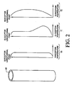
- a typical uniform temperature distribution 71 shown in FIG. 2 can be achieved in the susceptor 60 by the induction of eddy currents in the susceptor 60.
- the material By placing a non-electrically conductive material near the susceptor 60 with a controlled temperature distribution, the material can be heated in a controlled manner.
- each coil section may have a variable number of turns per unit length to achieve a particular temperature distribution in the susceptor 60.
- the selection of coil length, number of turns per unit length, and other features of the coil sections are based on factors that include, but are not limited to, the size and shape of the susceptor that is to be heated, the type of susceptor temperature distribution desired, and the type of switching circuit.
- the duration of power provided by the power source 20 via switching circuit 30 to each one of the three coil sections is controlled by control circuit 50.
- temperature distribution 70 with uniform longitudinal heating, temperature distribution 71 with increased heating at one end, or temperature distribution 72 with increased middle section heating, as shown in FIG. 2 can be achieved in the susceptor 60 by the induction of eddy currents in the susceptor.
- Temperature distributions 70, 71 and 72 are typical distribution profiles for all embodiments of the invention that can be achieved by application of the present invention.
- One type of power source 20 for supplying the high frequency ac in all embodiments of the invention is a solid state power supply which utilizes solid-state high-power thyristor devices such as silicon-controlled rectifiers (SCRs).
- SCRs silicon-controlled rectifiers
- FIGs 1 and 2 of U.S. Pat. No. 5,165,049 A block diagram of a typical power source used with induction heating apparatus, and an inverter circuit used in die power source, is described and depicted in Figures 1 and 2 of U.S. Pat. No. 5,165,049 .
- the power source in the referenced patent is used with an induction furnace (melt charge), an artisan will appreciate its use with a susceptor 60 in place of an induction furnace.
- the RLC circuit shown in Figure 1 of the referenced patent represents a coil section, or load, in the present invention.
- Suitable switching circuits 31, 32 for switching power to each of the three coil sections 81, 82 and 83, in FIG. 1 is circuitry including SCRs for electronic switching of power from the power source 20 between coil sections.
- the control circuit 50 can be used in all embodiments of the invention to adjust commutation of the SCRs used in the inverter of the power source 20 to maintain a constant inverter power output when the load impedance (coil sections 81, 82 and 83) changes due to switching between the coil sections by the switching circuits 31, 32.
- One particular type of control circuit that can be used is described in U.S. Patent No. 5,523,631 .
- inverter output power level is controlled when switching among a number of inductive loads.
- the coil sections 81, 82 and 83 represent the switched inductive loads.
- the power set potentiometer associated with each switched inductive load in the referenced patent can be used to set a desired average power level defined by the duration of power application to each of the coil sections 81, 82 and 83. Additional control features disclosed in the referenced patent, including means for adjusting the output of the power source (inverter) to each coil section based upon the overshoot or undershoot of the power value provided to the coil section during the previous switching cycle, are also applicable to the control circuit 50 and power source 20 of the present invention.
- One or more temperature sensors can be provided in or near the susceptor 60.
- the sensors can be used to provide feedback signals for the control circuit 50 to adjust the output of the power source 20 and the duration of the source's connection to each coil section by the switching circuitry, so that the temperature distribution along the length of the susceptor 60 can be closely regulated.
- the present invention provides a flexible and adaptable induction heating device for controlling temperature distribution.
- the control circuit of the invention and the construction of the multi-section induction coil greatly reduces the complexity and cost of the power source while providing greater efficiency and productivity.
Landscapes
- Physics & Mathematics (AREA)
- Electromagnetism (AREA)
- General Induction Heating (AREA)
Applications Claiming Priority (2)
| Application Number | Priority Date | Filing Date | Title |
|---|---|---|---|
| US09/187,562 US6121592A (en) | 1998-11-05 | 1998-11-05 | Induction heating device and process for the controlled heating of a non-electrically conductive material |
| EP99971998A EP1046321B1 (en) | 1998-11-05 | 1999-10-25 | Induction heating device and process for controlling temperature distribution |
Related Parent Applications (1)
| Application Number | Title | Priority Date | Filing Date |
|---|---|---|---|
| EP99971998A Division EP1046321B1 (en) | 1998-11-05 | 1999-10-25 | Induction heating device and process for controlling temperature distribution |
Publications (2)
| Publication Number | Publication Date |
|---|---|
| EP1718117A1 EP1718117A1 (en) | 2006-11-02 |
| EP1718117B1 true EP1718117B1 (en) | 2008-08-06 |
Family
ID=22689475
Family Applications (2)
| Application Number | Title | Priority Date | Filing Date |
|---|---|---|---|
| EP06117255A Expired - Lifetime EP1718117B1 (en) | 1998-11-05 | 1999-10-25 | Induction Heating Device and Process for Controlling Temperature Distribution |
| EP99971998A Expired - Lifetime EP1046321B1 (en) | 1998-11-05 | 1999-10-25 | Induction heating device and process for controlling temperature distribution |
Family Applications After (1)
| Application Number | Title | Priority Date | Filing Date |
|---|---|---|---|
| EP99971998A Expired - Lifetime EP1046321B1 (en) | 1998-11-05 | 1999-10-25 | Induction heating device and process for controlling temperature distribution |
Country Status (7)
| Country | Link |
|---|---|
| US (1) | US6121592A (enExample) |
| EP (2) | EP1718117B1 (enExample) |
| JP (1) | JP4450999B2 (enExample) |
| AU (1) | AU1229800A (enExample) |
| CA (1) | CA2317649C (enExample) |
| DE (2) | DE69939284D1 (enExample) |
| WO (1) | WO2000028787A1 (enExample) |
Families Citing this family (35)
| Publication number | Priority date | Publication date | Assignee | Title |
|---|---|---|---|---|
| JP4271790B2 (ja) * | 1999-09-22 | 2009-06-03 | 東芝テック株式会社 | 定着装置 |
| US7141768B2 (en) | 2000-04-28 | 2006-11-28 | Nexicor, Llc | Fastening device |
| IT1321031B1 (it) * | 2000-10-17 | 2003-12-30 | Minipack Torre Spa | Dispositivo a induzione per la retrazione di film termoretraibili suprodotti da confezionare, sistema di confezionamento comprendente tale |
| US6992406B2 (en) * | 2001-08-14 | 2006-01-31 | Inductotherm Corp. | Induction heating or melting power supply utilizing a tuning capacitor |
| GB0324831D0 (en) * | 2003-10-24 | 2003-11-26 | British Nuclear Fuels Plc | Induction heating |
| US6993061B2 (en) * | 2003-11-07 | 2006-01-31 | Battelle Energy Alliance, Llc | Operating an induction melter apparatus |
| US7323666B2 (en) | 2003-12-08 | 2008-01-29 | Saint-Gobain Performance Plastics Corporation | Inductively heatable components |
| RU2330743C2 (ru) * | 2004-10-14 | 2008-08-10 | Николай Павлович Селиванов | Способ изготовления гофрированной трубы, предпочтительно жаровой, технологический комплекс для изготовления гофрированных труб, предпочтительно жаровых, стан для гофрирования трубчатых заготовок, предпочтительно при изготовлении жаровых труб, устройство для локального разогрева токами высокой частоты трубы при прокатке ее гофр, гофрированная труба, предпочтительно жаровая |
| US9370049B2 (en) * | 2004-12-08 | 2016-06-14 | Inductotherm Corp. | Electric induction heating, melting and stirring of materials non-electrically conductive in the solid state |
| US7582851B2 (en) * | 2005-06-01 | 2009-09-01 | Inductotherm Corp. | Gradient induction heating of a workpiece |
| DE202005012523U1 (de) * | 2005-08-05 | 2006-12-21 | Rs Elektronik Gmbh | Vorrichtung zum induktiven Erwärmen von Werkzeugaufnahmen |
| US7466740B2 (en) * | 2005-12-07 | 2008-12-16 | Ajax Tocco Magnethermic Corporation | Induction coil having internal and external faradic rings |
| AU2007204999A1 (en) * | 2006-01-09 | 2007-07-19 | Inductotherm Corp. | Electromagnetically shielded induction heating apparatus |
| EP1974589A2 (en) * | 2006-01-09 | 2008-10-01 | Inductotherm Corp. | Induction heating apparatus for strip materials with variable parameters |
| DE102006032640B4 (de) * | 2006-07-13 | 2010-07-01 | Ema Indutec Gmbh | Umrichter, insbesondere zur Erzeugung von Wirkleistung für die induktive Erwärmung und Verfahren zum induktiven Schmelzen und Rühren |
| BRPI0716037A2 (pt) | 2006-08-07 | 2013-09-24 | Messier Bugatti | mÉtodo de densificaÇço de um substrato poroso; e reator para densificaÇço de prÉ-formas porosas usando um precursor matriz lÍquido |
| EP1945003B1 (en) * | 2007-01-12 | 2011-03-16 | Inductotherm Corp. | Directional solidification of a metal |
| US20080267251A1 (en) * | 2007-04-30 | 2008-10-30 | Gerszewski Charles C | Stacked induction furnace system |
| US8884199B2 (en) * | 2007-11-03 | 2014-11-11 | Inductotherm Corp. | Electric power system for electric induction heating and melting of materials in a susceptor vessel |
| JP5321210B2 (ja) * | 2009-04-10 | 2013-10-23 | 三菱電機株式会社 | 可変分散補償器 |
| RU2439772C2 (ru) * | 2009-06-01 | 2012-01-10 | Федеральное государственное автономное образовательное учреждение высшего профессионального образования "Уральский федеральный университет имени первого Президента России Б.Н. Ельцина" | Трехфазный с нулевым выводом двухчастотный инвертор напряжения для индукционного нагрева (варианты) |
| FR2951606B1 (fr) * | 2009-10-19 | 2012-01-06 | Electricite De France | Procede de chauffage par induction mis en oeuvre dans un dispositif comprenant des inducteurs couples magnetiquement |
| CN101782324B (zh) * | 2010-02-05 | 2011-09-28 | 新星化工冶金材料(深圳)有限公司 | 控制铝钛硼(碳)合金中TiB2(TiC)颗粒团平均名义直径的电磁感应熔炼电炉 |
| JP5534318B2 (ja) * | 2010-03-09 | 2014-06-25 | 高周波熱錬株式会社 | 電力供給装置 |
| CN103184435A (zh) * | 2011-12-27 | 2013-07-03 | 北京北方微电子基地设备工艺研究中心有限责任公司 | 一种加热装置、加热方法及半导体加工设备 |
| US10321524B2 (en) | 2014-01-17 | 2019-06-11 | Nike, Inc. | Conveyance curing system |
| US20150202830A1 (en) * | 2014-01-17 | 2015-07-23 | Nike, Inc. | Adjustable Conveyance Curing Method |
| US9677700B2 (en) * | 2014-10-27 | 2017-06-13 | Ajax Tocco Magnethermic Corporation | Pipe heating apparatus and methods for uniform end heating and controlled heating length |
| WO2017068098A1 (en) * | 2015-10-22 | 2017-04-27 | Philip Morris Products S.A. | Inductive heating device for heating an aerosol-forming substrate comprising a susceptor |
| DE102015016831A1 (de) * | 2015-12-28 | 2017-06-29 | Haimer Gmbh | Schrumpfgerät mit Heizkontrolle |
| CN110023537B (zh) * | 2016-09-19 | 2021-11-16 | 阿卜杜拉国王科技大学 | 基座 |
| KR102306832B1 (ko) * | 2016-10-19 | 2021-09-28 | 니코벤처스 트레이딩 리미티드 | 유도 가열 배열체 |
| KR101959633B1 (ko) * | 2017-09-29 | 2019-03-18 | 한전케이피에스 주식회사 | 발전기 리테이닝 링 유도가열 장치 및 방법 |
| US11956878B2 (en) * | 2019-07-24 | 2024-04-09 | Japan Tobacco Inc. | Methods and system for induction heating |
| DE102020103871A1 (de) | 2020-02-14 | 2021-08-19 | E. Zoller GmbH & Co. KG Einstell- und Messgeräte | Prozessgesteuerte Energieversorgung einer Induktionsspule zur Erwärmung von Warmschrumpffuttern |
Family Cites Families (11)
| Publication number | Priority date | Publication date | Assignee | Title |
|---|---|---|---|---|
| US4241250A (en) * | 1979-06-25 | 1980-12-23 | General Electric Company | Induction cooking system |
| US4506131A (en) * | 1983-08-29 | 1985-03-19 | Inductotherm Industries Inc. | Multiple zone induction coil power control apparatus and method |
| US4600823A (en) * | 1984-01-31 | 1986-07-15 | Sanyo Electric Co., Ltd. | Induction heating apparatus having adjustable heat output |
| JP2530812B2 (ja) * | 1985-12-12 | 1996-09-04 | 富士電機株式会社 | 高周波誘導加熱装置 |
| US5165049A (en) * | 1990-04-02 | 1992-11-17 | Inductotherm Corp. | Phase difference control circuit for induction furnace power supply |
| US5079399A (en) * | 1990-08-06 | 1992-01-07 | Denki Kogyo Co., Ltd. | High-frequency induction heating apparatus |
| GB2269465A (en) * | 1992-08-06 | 1994-02-09 | Inductotherm Europ | Induction heating |
| US5523631A (en) * | 1993-08-25 | 1996-06-04 | Inductotherm Corp. | Control system for powering plural inductive loads from a single inverter source |
| US5508497A (en) * | 1994-02-02 | 1996-04-16 | Abb Patent Gmbh | Method for open-loop/closed-loop control of at least two parallel oscillating circuit inverters feeding induction furnaces |
| JPH08264272A (ja) * | 1995-03-27 | 1996-10-11 | Seta Giken:Kk | 電磁誘導加熱装置 |
| US5908575A (en) * | 1997-05-16 | 1999-06-01 | Gas Research Institute | Method of inductively fusion joining plastic pipes |
-
1998
- 1998-11-05 US US09/187,562 patent/US6121592A/en not_active Expired - Lifetime
-
1999
- 1999-10-25 DE DE69939284T patent/DE69939284D1/de not_active Expired - Lifetime
- 1999-10-25 JP JP2000581857A patent/JP4450999B2/ja not_active Expired - Lifetime
- 1999-10-25 DE DE69933432T patent/DE69933432T2/de not_active Expired - Lifetime
- 1999-10-25 CA CA002317649A patent/CA2317649C/en not_active Expired - Fee Related
- 1999-10-25 EP EP06117255A patent/EP1718117B1/en not_active Expired - Lifetime
- 1999-10-25 AU AU12298/00A patent/AU1229800A/en not_active Abandoned
- 1999-10-25 EP EP99971998A patent/EP1046321B1/en not_active Expired - Lifetime
- 1999-10-25 WO PCT/US1999/024980 patent/WO2000028787A1/en not_active Ceased
Also Published As
| Publication number | Publication date |
|---|---|
| CA2317649C (en) | 2009-02-03 |
| EP1718117A1 (en) | 2006-11-02 |
| DE69933432D1 (de) | 2006-11-16 |
| DE69933432T2 (de) | 2007-08-23 |
| JP4450999B2 (ja) | 2010-04-14 |
| WO2000028787A1 (en) | 2000-05-18 |
| EP1046321B1 (en) | 2006-10-04 |
| EP1046321A1 (en) | 2000-10-25 |
| CA2317649A1 (en) | 2000-05-18 |
| DE69939284D1 (de) | 2008-09-18 |
| AU1229800A (en) | 2000-05-29 |
| JP2002529906A (ja) | 2002-09-10 |
| US6121592A (en) | 2000-09-19 |
| EP1046321A4 (en) | 2004-04-21 |
| WO2000028787A9 (en) | 2000-09-28 |
Similar Documents
| Publication | Publication Date | Title |
|---|---|---|
| EP1718117B1 (en) | Induction Heating Device and Process for Controlling Temperature Distribution | |
| EP0641145B1 (en) | Control system for powering plural inductive loads from a single inverter source | |
| EP1221826B1 (en) | Transverse flux induction heating apparatus | |
| KR101433054B1 (ko) | 워크피스의 유도 가열처리 | |
| EP2135483B1 (en) | Current fed inverter with pulse regulator for electric induction heating, melting and stirring | |
| US4755648A (en) | Cyclical, multiple frequency high-frequency induction heating apparatus | |
| RU2366117C2 (ru) | Сканирующий индукционный нагрев | |
| US20090314768A1 (en) | Gradient Induction Heating of a Workpiece | |
| EP1829426B1 (en) | Electric induction control system | |
| JP2002529906A5 (enExample) | ||
| US5426663A (en) | Glass melting | |
| US4531037A (en) | Process and means to control the average heating power induced in a flat conducting product maintained electromagnetically in position without contact | |
| CN101658066A (zh) | 用于电感应加热、熔化和搅拌的具有脉冲调节器的电流反馈逆变器 | |
| JP3510167B2 (ja) | 高周波加熱方法 | |
| MXPA00005550A (en) | Induction heating device and process for controlling temperature distribution | |
| RU2151201C1 (ru) | Способ индукционного градиентного нагрева и устройство для его реализации | |
| JPH0597443A (ja) | ガラスの電気溶融炉 | |
| JPH0821465B2 (ja) | 誘導加熱装置 | |
| EP1006757B1 (en) | Magnetic heating system | |
| US8071921B2 (en) | Method to supply electric current to a tube furnace | |
| RU2256304C2 (ru) | Индукционная установка сквозного нагрева мерных заготовок | |
| SU815976A1 (ru) | Индуктор дл нагрева металлическихзАгОТОВОК пОд плАСТичЕСКуюдЕфОРМАцию | |
| HK1097688A (en) | Gradient induction heating of a workpiece | |
| JPH07806B2 (ja) | 高周波通電焼入装置 | |
| HU186750B (en) | Method and apparatus for melting charges in arc furnace |
Legal Events
| Date | Code | Title | Description |
|---|---|---|---|
| PUAI | Public reference made under article 153(3) epc to a published international application that has entered the european phase |
Free format text: ORIGINAL CODE: 0009012 |
|
| 17P | Request for examination filed |
Effective date: 20060714 |
|
| AC | Divisional application: reference to earlier application |
Ref document number: 1046321 Country of ref document: EP Kind code of ref document: P |
|
| AK | Designated contracting states |
Kind code of ref document: A1 Designated state(s): DE FR IT |
|
| AKX | Designation fees paid |
Designated state(s): DE FR IT |
|
| 17Q | First examination report despatched |
Effective date: 20070618 |
|
| GRAC | Information related to communication of intention to grant a patent modified |
Free format text: ORIGINAL CODE: EPIDOSCIGR1 |
|
| GRAP | Despatch of communication of intention to grant a patent |
Free format text: ORIGINAL CODE: EPIDOSNIGR1 |
|
| GRAS | Grant fee paid |
Free format text: ORIGINAL CODE: EPIDOSNIGR3 |
|
| GRAA | (expected) grant |
Free format text: ORIGINAL CODE: 0009210 |
|
| RAP1 | Party data changed (applicant data changed or rights of an application transferred) |
Owner name: INDUCTOTHERM CORP. |
|
| RIN1 | Information on inventor provided before grant (corrected) |
Inventor name: PEYSAKHOVICH, VITALY, A. Inventor name: THE OTHER INVENTORS HAVE AGREED TO WAIVE THEIR ENT Inventor name: LAMPI, RUDOLPH, K. Inventor name: FISHMAN, OLEG |
|
| AC | Divisional application: reference to earlier application |
Ref document number: 1046321 Country of ref document: EP Kind code of ref document: P |
|
| AK | Designated contracting states |
Kind code of ref document: B1 Designated state(s): DE FR IT |
|
| REF | Corresponds to: |
Ref document number: 69939284 Country of ref document: DE Date of ref document: 20080918 Kind code of ref document: P |
|
| PLBE | No opposition filed within time limit |
Free format text: ORIGINAL CODE: 0009261 |
|
| STAA | Information on the status of an ep patent application or granted ep patent |
Free format text: STATUS: NO OPPOSITION FILED WITHIN TIME LIMIT |
|
| 26N | No opposition filed |
Effective date: 20090507 |
|
| PGFP | Annual fee paid to national office [announced via postgrant information from national office to epo] |
Ref country code: DE Payment date: 20091022 Year of fee payment: 11 |
|
| PGFP | Annual fee paid to national office [announced via postgrant information from national office to epo] |
Ref country code: FR Payment date: 20091029 Year of fee payment: 11 Ref country code: IT Payment date: 20091021 Year of fee payment: 11 |
|
| PG25 | Lapsed in a contracting state [announced via postgrant information from national office to epo] |
Ref country code: FR Free format text: LAPSE BECAUSE OF NON-PAYMENT OF DUE FEES Effective date: 20101102 |
|
| REG | Reference to a national code |
Ref country code: FR Ref legal event code: ST Effective date: 20110630 |
|
| REG | Reference to a national code |
Ref country code: DE Ref legal event code: R119 Ref document number: 69939284 Country of ref document: DE Effective date: 20110502 |
|
| PG25 | Lapsed in a contracting state [announced via postgrant information from national office to epo] |
Ref country code: IT Free format text: LAPSE BECAUSE OF NON-PAYMENT OF DUE FEES Effective date: 20101025 |
|
| PG25 | Lapsed in a contracting state [announced via postgrant information from national office to epo] |
Ref country code: DE Free format text: LAPSE BECAUSE OF NON-PAYMENT OF DUE FEES Effective date: 20110502 |