EP1716546B1 - Beverage vending machine with cup release device - Google Patents
Beverage vending machine with cup release device Download PDFInfo
- Publication number
- EP1716546B1 EP1716546B1 EP05707784A EP05707784A EP1716546B1 EP 1716546 B1 EP1716546 B1 EP 1716546B1 EP 05707784 A EP05707784 A EP 05707784A EP 05707784 A EP05707784 A EP 05707784A EP 1716546 B1 EP1716546 B1 EP 1716546B1
- Authority
- EP
- European Patent Office
- Prior art keywords
- cup
- vending machine
- beverage vending
- stacks
- turret
- Prior art date
- Legal status (The legal status is an assumption and is not a legal conclusion. Google has not performed a legal analysis and makes no representation as to the accuracy of the status listed.)
- Expired - Lifetime
Links
- 235000013361 beverage Nutrition 0.000 title claims abstract description 38
- 230000000284 resting effect Effects 0.000 claims description 6
- 230000004308 accommodation Effects 0.000 description 7
- 238000006073 displacement reaction Methods 0.000 description 2
- 230000000694 effects Effects 0.000 description 2
- 230000005484 gravity Effects 0.000 description 2
- 235000020965 cold beverage Nutrition 0.000 description 1
- 235000012171 hot beverage Nutrition 0.000 description 1
- 230000003993 interaction Effects 0.000 description 1
- 238000012986 modification Methods 0.000 description 1
- 230000004048 modification Effects 0.000 description 1
- 238000005381 potential energy Methods 0.000 description 1
- 238000004513 sizing Methods 0.000 description 1
Images

Classifications
-
- G—PHYSICS
- G07—CHECKING-DEVICES
- G07F—COIN-FREED OR LIKE APPARATUS
- G07F13/00—Coin-freed apparatus for controlling dispensing or fluids, semiliquids or granular material from reservoirs
- G07F13/10—Coin-freed apparatus for controlling dispensing or fluids, semiliquids or granular material from reservoirs with associated dispensing of containers, e.g. cups or other articles
Definitions
- the present invention refers to a beverage vending machine provided with a cup release device.
- beverage vending machines for dispensing beverages filled into cups, which comprise a movable turret accommodating one or more stacks of cups, as well as devices enabling such cups to be pulled out one at a time, in view to be then filled with a selected beverage.
- These devices are known to exist in a variety of forms and embodiments.
- a very simple one among these embodiments is constituted by a pair of spirals arranged at the base of said turret close to the outlet section of a stack of cups, so as to be able to interact with the upper edge of a cup and cause the latter to be released from the stack through a rotation about the coiling axis thereof.
- a device of such kind has a number of drawbacks.
- One of such drawbacks is for instance due to the fact that the device is not capable of working as efficiently when it is due to release differently sized or shaped cups, or when the clearance or spacing between the upper edges of two successive cups in a stack is not constant. In practice, this may cause two or more stacked cups to be released at the same time, thereby bringing about a situation that may in turn quite easily cause the vending machine to get jammed with a resulting loss in revenues for those who run the vending business.
- a further drawback connected to these devices based on the use of rotating spirals lies in the fact that they make use of the force of gravity for releasing a cup from a stack.
- the stacked cups are provided to already contain the product needed for the preparation of the final beverage, their falling down caused by the action of the spirals entails a partial loss of said products from the cups themselves, so that the resulting spillage scatters all over the vending machine with a diffuse soiling effect.
- the cup release device disclosed in US 4,327,843 shares the same drawback as the afore-described prior-art device concerning the spillage, and resulting scattering inside the vending machine, of the products that may be possibly held in the stacked cups, when the same cups are so removed from the stack for the preparation of the beverage.
- a further drawback of this device lies in the fact that the movement of the juts supporting the stack of cups is caused and controlled by the displacement of the cup being removed and this by no means ensures that a single cup is actually removed each time.
- the gripping arm would clamp both of them and the juts would be pushed apart by both upper edges of the two cups.
- the sole pulling action exerted on the cup to be removed might not prove sufficient to separate from each other two cups that are so stuck into each other, especially if the spacing between the upper edges of such successive cups in a stack is so small that said upper edges come to almost rest against each other.
- US 6 102 246 discloses a beverage vending machine comprising: a turret for accommodating one or more stacks of cups, support means associated to the turret which cooperate with the first cup in order to support the stack, an arm moving between a release position and a gripping position, and provided with jaws capable of moving relative to each other and a receptacle comprising one or more compartments for receiving cups removed from the stack.
- a beverage vending machine provided with a cup release device, which is effective in ensuring that a single cup at a time is released from a stack, regardless of the size of such cup, the spacing separating a cup from a successive one in said stack, and the material which the cup is made of.
- Another purpose of the present invention is to provide a beverage vending machine provided with a cup release device, which is effective in preventing possible products contained in each cup of a stack for the preparation of a final beverage from spilling over and scattering inside the vending machine.
- Another purpose yet of the present invention is to provide a beverage vending machine provided with a cup release device, which requires a single drive unit for actuating said device.
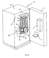
- Figure 1 illustrates schematically a vending machine 1 provided with a door 2 that closes a chamber 3 defined by the walls of a cabinet or outer casing 4.
- the door 2 id in turn provided with an aperture that forms a dispensing site 5 for taking out the beverage prepared by the vending machine 1.
- a selection device 6 of a kind known as such in the art, such as for instance a push-button panel or unit, for buyers to select the beverage they wish to drink.
- This selector device 6 may also integrate means for paying the selected beverage, as they may for instance be constituted by a magnetic card reader or a coin collector.
- the vending machine 1 may of course comprise more than a single dispensing site 5, according to the actual requirements and needs.
- a turret 7 provided with one or more accommodations 8 adapted to receive and hold a corresponding number of stacks 9 of cups.
- the turret 7 is preferably rotating about the longitudinal axis thereof and may be adapted to accommodate and hold differently sized cups through a proper conformation of the accommodations 8.
- These support means 13 are placed on an end section of each accommodation 8 and are preferably connected in an oscillating manner to the turret 7; they are further preferably movable against the action of elastic means.
- These support means 13 may be provided in any number whatsoever, according to the conformation of the turret 7 and the cups.
- a single stack 9 of cups, as arranged within an accommodation 8, and a receptacle 11 with a single compartment 12 have been represented in Figure 1 . It will be readily appreciated, however, that more than just a single stack 9 and just a single compartment 12 may be provided as well.
- the vending machine 1 further comprises an arm 14, which, as best illustrated in Figures 2 and 3 , is movable between a first release position, in which the arm 14 lays down a cup 10 into a compartment 12 of the receptacle 11 ( Figure 2 ), and a second gripping position ( Figure 3 ), in which the arm 14 removes a cup 10 from a stack 9 provided within an accommodation 8 of the turret 7.
- the arm 14 is mounted slidably on a runner 15 arranged so that the first cup-release position of the arm comes to be situated in the proximity of the receptacle 11 and the second cup gripping position of the arm lies in the proximity of the first cup 10 of each one of the stacks 9, i.e.
- the runner 15 may be arranged so as to lie in correspondence to the longitudinal axis of rotation of the turret 7.
- the movement of the arm 14 between the above-mentioned first and second positions is imparted by driving means of a kind known as such in the art (and not shown in the Figures).
- the arm14 is further provided with a first jaw 16a and a second jaw 16b, which are movable reciprocally, i.e. relative to each other. This mutual position of the two jaws enables the arm 14 to accommodate different sizes of cups, whereas the same jaws moving apart from each other enable the cup they had previously picked from a stack 9 to be released into a compartment 12 of the receptacle 11.
- Figure 4 illustrates the jaws 16a and 16b of the moving arm 14 and the support means 13 that are associated to the turret 7 in order to enable a cup 10 to be removed and released from a stack 9 of cups.
- the second jaw 16b comprises actuation means 17 that cooperate with the support means 13 to remove a cup 10 from a stack 9 of cups.
- actuation means 17 may be provided either on a single one or both jaws 16a and 16b, depending on the arrangement of the support means 13 on the turret 7; in a preferred manner, they consist of jutting parts.
- At least one of said jaws 16a and 16b comprises at least a moving hook 18 that gets caught between the upper edge 19 of the first cup 10 of a stack 9 and the upper edge 20 of the cup 10' immediately following said first cup 10 in said stack 9 when the arm 14 is in its second gripping position illustrated in Figure 3 .
- their number and arrangement on either the jaw 16a or the jaw 16b, or even both jaws 16a and 16b may be selected so as to for instance most suitably fit a particular shape of the cups.
- Each moving hook 18 comprises a shoe 21 that is so shaped as to be adapted to slide on at least a surface 22 of the turret 7, thereby causing the same hook 18 to displace.
- Each such hook 18 is preferably movable against the action of elastic means.
- the support means 13, which are preferably connected in a swinging manner to the turret 7, comprise a retainer 25 that is so shaped as to be adapted to engage the upper edge 19 of the cup 10.
- the retainer 25, which the latter are provided with is given a cam-like profile 26 for said actuation means 17 to slide thereon.
- the actuation means 17, the support means 13, each hook 18 and the related shoe 21, as well as the surface 22 jointly form a cup release device.
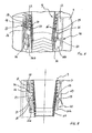
- FIGs 5 , 6 and 7 Three distinct moments in the operation of such cup release device are illustrated in Figures 5 , 6 and 7 .
- the arm 14 is displaced along the runner 15 towards the second gripping position thereof illustrated in Figure 3 .
- the jaws 16a and 16b are suitably spaced apart so as to define a resting surface 23 for the upper edge 19 of the first cup 10 of a stack 9. The extent to which the jaws 16a and 16b are spaced from each other, i.e.
- each hook 18 moves into contact with the surface 22 of the turret 7.
- this surface 22 being preferably constituted by a fork-like structure 27 comprising at least a plane 24 that is inclined relative to the longitudinal axis of the turret 7, the shoe 21 is capable of sliding on this plane 24, thereby driving the hook 18 into moving.
- Each hook 18 is preferably formed by a plate having a first end portion bent in a hook-like manner and a second end portion that is pivotally connected to one of the two jaws 16a, 16b.
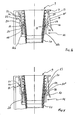
- the arm 14 is shown to have reached the position in which it is gripping the first cup 10 of the stack 9.
- the resting surface 23 is in contact with the upper edge 19 of the cup 10 and, under the circumstances, said surface 23 is supporting the entire stack 9 of cups, actually.
- the actuation means 17, by sliding along the cam-like profile 26, have caused the retainer 25 to disengage the upper edge 19 of the first cup 10 of the stack 9.
- the instant at which the retainer 25 releases the edge 19 is substantially the same as the one at which the latter enters into contact with the resting surface 23.
- it is still substantially the same as the instant at which each hook 18 moves in between the upper edge 19 of the first cup 10 and the upper edge 20 of the next cup 10' following said first cup 10 in said stack 9.
- each hook 18 may be constituted by a body that is capable of deflecting under a shear force without any rupture and/or permanent set.
- FIG. 7 Illustrated in Figure 7 is the arm 14 while it moves away from its gripping position upon having removed the cup 10 from the stack 9.
- Each hook 18 exerts a pulling force upon the cup 10, and its being so engaged between the upper edges 19 and 20 of two successive cups 10 and 10' ensures that a single cup at a time is removed from said stack 9.
- the arm 14 moving so away from the gripping position thereof enables the actuation means 17 to leave, i.e. separate from the cam-like profile 26, thereby enabling the retainer 25 to engage the upper edge 20 of the next cup 10' following the one that has just been removed from the stack 9.
- This stack 9 comes in this way to be again supported by the support means 13. Thanks to the particular conformation of the cam-like profile 26, at the very moment at which the cup 10 is removed from the stack 9, the support means 13 are capable of engaging the next cup 10', thereby sustaining again the stack 9 and pegging it in position.
- the shoe 21 moves again into contact with the surface 22, but this time it does so from the opposite side of the inclined plane 24, as compared with the direction of movement shown in Figure 6 .
- the surface 22 is preferably associated to the turret 7 pivotally, so that the same shoe is capable to displace the surface 22 as it slides away from the gripping position.
- Such displacement of the surface 22 caused by the shoe 21 has the sole effect of allowing an unhindered passage of the same shoe 21.
- the fork-like structure 27 of the surface 22 may be constituted by some thin plate that is capable of deflecting under a shear force without any rupture and/or permanent set.
- the arm 14 moves towards the release position thereof in the proximity of the receptacle 11, so as this is illustrated in Figure 2 .
- the opening out of the jaws 16a and 16b as brought about by the same motive means that drive the arm 14 to and from the gripping and release positions thereof, causes the cup 10 to be released and deposited into compartment 12 of said receptacle 11.
- the cup 10 may then be conveyed - in a continuous manner or through a sequence of individual steps - from the receptacle 11 towards any device as may be provided for the preparation of hot or cold beverages, or towards any other device as may be provided to dispense loose edible products requiring being let into a cup prior to being vended out.
- the cup 10, as filled in this way with the desired product or - at most - even empty, will be eventually conveyed towards a delivery or dispensing site 5, which may possibly be common to the one of other dispensing devices comprised in the same vending machine 1, such as for instance a packaged-product dispensing device.
- the present invention can advantageously work with widely varying types of cups, without any replacement of parts being actually required in the vending machine to this purpose.
Landscapes
- Physics & Mathematics (AREA)
- General Physics & Mathematics (AREA)
- Beverage Vending Machines With Cups, And Gas Or Electricity Vending Machines (AREA)
- Table Devices Or Equipment (AREA)
Applications Claiming Priority (2)
| Application Number | Priority Date | Filing Date | Title |
|---|---|---|---|
| IT000008A ITPN20040008A1 (it) | 2004-02-09 | 2004-02-09 | Distributore automatico di bevande con dispositivo di sgancio bicchieri |
| PCT/EP2005/050160 WO2005076235A1 (en) | 2004-02-09 | 2005-01-17 | Beverage vending machine with cup release device |
Publications (2)
| Publication Number | Publication Date |
|---|---|
| EP1716546A1 EP1716546A1 (en) | 2006-11-02 |
| EP1716546B1 true EP1716546B1 (en) | 2010-10-20 |
Family
ID=34835607
Family Applications (1)
| Application Number | Title | Priority Date | Filing Date |
|---|---|---|---|
| EP05707784A Expired - Lifetime EP1716546B1 (en) | 2004-02-09 | 2005-01-17 | Beverage vending machine with cup release device |
Country Status (9)
| Country | Link |
|---|---|
| EP (1) | EP1716546B1 (enExample) |
| JP (1) | JP4833863B2 (enExample) |
| CN (1) | CN100565598C (enExample) |
| AT (1) | ATE485575T1 (enExample) |
| DE (1) | DE602005024236D1 (enExample) |
| DK (1) | DK1716546T3 (enExample) |
| ES (1) | ES2353523T3 (enExample) |
| IT (1) | ITPN20040008A1 (enExample) |
| WO (1) | WO2005076235A1 (enExample) |
Cited By (1)
| Publication number | Priority date | Publication date | Assignee | Title |
|---|---|---|---|---|
| FR3143960A1 (fr) * | 2022-12-27 | 2024-06-28 | Kodashi | Machine de distribution de vrac |
Families Citing this family (13)
| Publication number | Priority date | Publication date | Assignee | Title |
|---|---|---|---|---|
| IT1403912B1 (it) * | 2011-02-04 | 2013-11-08 | Poleni | Distributore automatico di alimenti e prodotti in genere |
| CA2846821A1 (en) * | 2011-08-26 | 2013-03-07 | Crane Merchandising Systems, Inc. | Planetary gear drive cup turret for cup drop unit in beverage vending machine |
| DE102012207665B4 (de) * | 2012-05-08 | 2017-02-09 | Sielaff Gmbh & Co. Kg Automatenbau | Getränkeautomat, Verfahren zum Betreiben eines Getränkeautomaten |
| FR3035731B1 (fr) * | 2015-04-28 | 2017-05-05 | Photo-Me Int Plc | Dispositif de stockage et de distribution de consommables |
| IT201600124688A1 (it) * | 2016-12-09 | 2018-06-09 | Ilventitre S R L | "dispositivo per la preparazione e la consegna di un cono o coppetta di gelato" |
| IT201700043567A1 (it) * | 2017-04-20 | 2018-10-20 | N&W Global Vending S P A | Distributore di contenitori monouso per la preparazione di bevande |
| CN107578546A (zh) * | 2017-09-26 | 2018-01-12 | 谢启浩 | 共享饮水机 |
| RU2727979C1 (ru) * | 2017-10-19 | 2020-07-28 | Эвока С.П.А. | Устройство для выдачи предметов из стопки вложенных друг в друга предметов, в частности крышек стаканчиков |
| CN107833390A (zh) * | 2017-12-12 | 2018-03-23 | 刘伟利 | 一种冰淇淋自动售卖机 |
| IT201900020940A1 (it) * | 2019-11-12 | 2021-05-12 | Evoca Spa | Unita' di erogazione di bicchieri per un distributore automatico di bevande |
| CN111012178B (zh) * | 2019-12-20 | 2022-01-25 | 北京怡盛原环保科技有限公司 | 一种便捷式壁挂式净水器 |
| KR102463345B1 (ko) * | 2021-01-26 | 2022-11-04 | 김완수 | 자동 음료 장치 |
| EP4579622A1 (en) * | 2023-12-26 | 2025-07-02 | Mixo Machine, S.L. | Vending machine |
Family Cites Families (12)
| Publication number | Priority date | Publication date | Assignee | Title |
|---|---|---|---|---|
| US4327843A (en) * | 1980-05-27 | 1982-05-04 | Corley Dewey A | Cup dispensing mechanism |
| GB2145071B (en) * | 1983-08-18 | 1986-06-18 | Peter Dixon Jones | Cup and like dispenser |
| FR2625888A1 (fr) * | 1988-01-20 | 1989-07-21 | App Automatiques Ste Indle | Dispositif de distribution de gobelets empiles |
| JPH03276296A (ja) * | 1990-03-26 | 1991-12-06 | Sanyo Electric Co Ltd | カップ式自動販売機のカップ保持装置 |
| GB9214034D0 (en) * | 1992-07-01 | 1992-08-12 | Gen Foods Ltd | Method and apparatus for dispensing cups and vending machines for beverages |
| JP3243918B2 (ja) * | 1994-02-23 | 2002-01-07 | 富士電機株式会社 | カップミキシング自動販売機の制御装置 |
| EP0704376A1 (de) * | 1994-09-30 | 1996-04-03 | Grapha-Holding Ag | Verfahren zur Bereitstellung von einer Beschickungseinrichtung zugeführten Behältern |
| JPH11161844A (ja) * | 1997-11-28 | 1999-06-18 | Kokoro:Kk | 加熱調理型自動販売機 |
| US6053359A (en) * | 1997-12-22 | 2000-04-25 | Mcdonald's Corporation | Automated beverage system |
| IT1304276B1 (it) * | 1998-04-15 | 2001-03-13 | Ducale Macchine Da Caffe Di Sa | Distributore automatico di bevande in bicchiere. |
| ITPN20000024A1 (it) * | 2000-04-20 | 2001-10-20 | Necta Vending Solutions Spa | Distributore automatico di bevande con meccanismo perfezionato di sgancio dei bicchieri |
| JP2003196734A (ja) * | 2001-12-26 | 2003-07-11 | Toshiba Electric Appliance Co Ltd | カップ供給装置 |
-
2004
- 2004-02-09 IT IT000008A patent/ITPN20040008A1/it unknown
-
2005
- 2005-01-17 DE DE602005024236T patent/DE602005024236D1/de not_active Expired - Lifetime
- 2005-01-17 AT AT05707784T patent/ATE485575T1/de active
- 2005-01-17 JP JP2006551832A patent/JP4833863B2/ja not_active Expired - Fee Related
- 2005-01-17 DK DK05707784.4T patent/DK1716546T3/da active
- 2005-01-17 ES ES05707784T patent/ES2353523T3/es not_active Expired - Lifetime
- 2005-01-17 EP EP05707784A patent/EP1716546B1/en not_active Expired - Lifetime
- 2005-01-17 CN CNB2005800002805A patent/CN100565598C/zh not_active Expired - Fee Related
- 2005-01-17 WO PCT/EP2005/050160 patent/WO2005076235A1/en not_active Ceased
Cited By (2)
| Publication number | Priority date | Publication date | Assignee | Title |
|---|---|---|---|---|
| FR3143960A1 (fr) * | 2022-12-27 | 2024-06-28 | Kodashi | Machine de distribution de vrac |
| WO2024141472A1 (fr) * | 2022-12-27 | 2024-07-04 | Kodashi | Machine de distribution de vrac |
Also Published As
| Publication number | Publication date |
|---|---|
| WO2005076235A1 (en) | 2005-08-18 |
| CN1771520A (zh) | 2006-05-10 |
| CN100565598C (zh) | 2009-12-02 |
| ITPN20040008A1 (it) | 2004-05-09 |
| ATE485575T1 (de) | 2010-11-15 |
| DE602005024236D1 (de) | 2010-12-02 |
| JP2007525751A (ja) | 2007-09-06 |
| EP1716546A1 (en) | 2006-11-02 |
| ES2353523T3 (es) | 2011-03-02 |
| JP4833863B2 (ja) | 2011-12-07 |
| DK1716546T3 (da) | 2011-01-24 |
Similar Documents
| Publication | Publication Date | Title |
|---|---|---|
| EP1716546B1 (en) | Beverage vending machine with cup release device | |
| US7900797B1 (en) | Lid separator and dispensing device | |
| EP3128874B1 (en) | Forward advancing cutlery dispenser | |
| EP2082379B1 (en) | Automatic product vending machine | |
| DE60309873T2 (de) | Vorrichtung und verfahren zum verkaufen von produkten in verschiedenen grössen | |
| US4591070A (en) | Article dispenser adjustable for different size articles | |
| JP3770406B2 (ja) | パックの混合を選択するための自動販売機 | |
| US3180518A (en) | Mechanical vendor for articles | |
| US4779760A (en) | Article release mechanism | |
| WO1992012921A1 (en) | Dispenser for soft drink lids or the like | |
| CN102084402B (zh) | 一种从贩卖机货架分发商品的方法 | |
| US2875877A (en) | Vending machines | |
| WO1995024700A1 (en) | Coin-operated dispensing machine | |
| US9251640B2 (en) | Horizontal lid dispenser | |
| US3554364A (en) | Control and cup-pushing assembly for dispensers | |
| US6789694B1 (en) | Napkin dispenser | |
| CN101163429B (zh) | 用于选择叠层中胶囊的装置 | |
| EP2363841A1 (en) | Product dispensing machine and dispensing method | |
| EP3129961B1 (en) | Vending machines | |
| US4327843A (en) | Cup dispensing mechanism | |
| US20020092861A1 (en) | Magazine vending machine | |
| US5433340A (en) | Vending device | |
| RU66739U1 (ru) | Устройство для удержания и выдачи товара в торговом автомате или полуавтомате | |
| EP2443972A1 (en) | System for feeding capsules containing a food product for producing a beverage or the like, particularly for vending machines | |
| GB2304705A (en) | Belt type dispenser with movable side walls |
Legal Events
| Date | Code | Title | Description |
|---|---|---|---|
| PUAI | Public reference made under article 153(3) epc to a published international application that has entered the european phase |
Free format text: ORIGINAL CODE: 0009012 |
|
| 17P | Request for examination filed |
Effective date: 20060911 |
|
| AK | Designated contracting states |
Kind code of ref document: A1 Designated state(s): AT BE BG CH CY CZ DE DK EE ES FI FR GB GR HU IE IS IT LI LT LU MC NL PL PT RO SE SI SK TR |
|
| DAX | Request for extension of the european patent (deleted) | ||
| GRAP | Despatch of communication of intention to grant a patent |
Free format text: ORIGINAL CODE: EPIDOSNIGR1 |
|
| GRAS | Grant fee paid |
Free format text: ORIGINAL CODE: EPIDOSNIGR3 |
|
| GRAA | (expected) grant |
Free format text: ORIGINAL CODE: 0009210 |
|
| RIN1 | Information on inventor provided before grant (corrected) |
Inventor name: JOHNDROW, JOHN PAUL17 FERNDALE ROAD |
|
| AK | Designated contracting states |
Kind code of ref document: B1 Designated state(s): AT BE BG CH CY CZ DE DK EE ES FI FR GB GR HU IE IS IT LI LT LU MC NL PL PT RO SE SI SK TR |
|
| REG | Reference to a national code |
Ref country code: GB Ref legal event code: FG4D |
|
| REG | Reference to a national code |
Ref country code: CH Ref legal event code: EP |
|
| GRAL | Information related to payment of fee for publishing/printing deleted |
Free format text: ORIGINAL CODE: EPIDOSDIGR3 |
|
| GRAS | Grant fee paid |
Free format text: ORIGINAL CODE: EPIDOSNIGR3 |
|
| REG | Reference to a national code |
Ref country code: IE Ref legal event code: FG4D |
|
| REF | Corresponds to: |
Ref document number: 602005024236 Country of ref document: DE Date of ref document: 20101202 Kind code of ref document: P |
|
| REG | Reference to a national code |
Ref country code: DK Ref legal event code: T3 |
|
| REG | Reference to a national code |
Ref country code: CH Ref legal event code: NV Representative=s name: HEPP WENGER RYFFEL AG |
|
| REG | Reference to a national code |
Ref country code: NL Ref legal event code: T3 |
|
| REG | Reference to a national code |
Ref country code: ES Ref legal event code: FG2A Effective date: 20110218 |
|
| LTIE | Lt: invalidation of european patent or patent extension |
Effective date: 20101020 |
|
| PG25 | Lapsed in a contracting state [announced via postgrant information from national office to epo] |
Ref country code: LT Free format text: LAPSE BECAUSE OF FAILURE TO SUBMIT A TRANSLATION OF THE DESCRIPTION OR TO PAY THE FEE WITHIN THE PRESCRIBED TIME-LIMIT Effective date: 20101020 |
|
| PG25 | Lapsed in a contracting state [announced via postgrant information from national office to epo] |
Ref country code: FI Free format text: LAPSE BECAUSE OF FAILURE TO SUBMIT A TRANSLATION OF THE DESCRIPTION OR TO PAY THE FEE WITHIN THE PRESCRIBED TIME-LIMIT Effective date: 20101020 Ref country code: IS Free format text: LAPSE BECAUSE OF FAILURE TO SUBMIT A TRANSLATION OF THE DESCRIPTION OR TO PAY THE FEE WITHIN THE PRESCRIBED TIME-LIMIT Effective date: 20110220 Ref country code: SE Free format text: LAPSE BECAUSE OF FAILURE TO SUBMIT A TRANSLATION OF THE DESCRIPTION OR TO PAY THE FEE WITHIN THE PRESCRIBED TIME-LIMIT Effective date: 20101020 Ref country code: SI Free format text: LAPSE BECAUSE OF FAILURE TO SUBMIT A TRANSLATION OF THE DESCRIPTION OR TO PAY THE FEE WITHIN THE PRESCRIBED TIME-LIMIT Effective date: 20101020 Ref country code: PT Free format text: LAPSE BECAUSE OF FAILURE TO SUBMIT A TRANSLATION OF THE DESCRIPTION OR TO PAY THE FEE WITHIN THE PRESCRIBED TIME-LIMIT Effective date: 20110221 Ref country code: BG Free format text: LAPSE BECAUSE OF FAILURE TO SUBMIT A TRANSLATION OF THE DESCRIPTION OR TO PAY THE FEE WITHIN THE PRESCRIBED TIME-LIMIT Effective date: 20110120 |
|
| PG25 | Lapsed in a contracting state [announced via postgrant information from national office to epo] |
Ref country code: GR Free format text: LAPSE BECAUSE OF FAILURE TO SUBMIT A TRANSLATION OF THE DESCRIPTION OR TO PAY THE FEE WITHIN THE PRESCRIBED TIME-LIMIT Effective date: 20110121 |
|
| PG25 | Lapsed in a contracting state [announced via postgrant information from national office to epo] |
Ref country code: CZ Free format text: LAPSE BECAUSE OF FAILURE TO SUBMIT A TRANSLATION OF THE DESCRIPTION OR TO PAY THE FEE WITHIN THE PRESCRIBED TIME-LIMIT Effective date: 20101020 Ref country code: EE Free format text: LAPSE BECAUSE OF FAILURE TO SUBMIT A TRANSLATION OF THE DESCRIPTION OR TO PAY THE FEE WITHIN THE PRESCRIBED TIME-LIMIT Effective date: 20101020 |
|
| PLBE | No opposition filed within time limit |
Free format text: ORIGINAL CODE: 0009261 |
|
| STAA | Information on the status of an ep patent application or granted ep patent |
Free format text: STATUS: NO OPPOSITION FILED WITHIN TIME LIMIT |
|
| PG25 | Lapsed in a contracting state [announced via postgrant information from national office to epo] |
Ref country code: PL Free format text: LAPSE BECAUSE OF FAILURE TO SUBMIT A TRANSLATION OF THE DESCRIPTION OR TO PAY THE FEE WITHIN THE PRESCRIBED TIME-LIMIT Effective date: 20101020 Ref country code: MC Free format text: LAPSE BECAUSE OF NON-PAYMENT OF DUE FEES Effective date: 20110131 Ref country code: RO Free format text: LAPSE BECAUSE OF FAILURE TO SUBMIT A TRANSLATION OF THE DESCRIPTION OR TO PAY THE FEE WITHIN THE PRESCRIBED TIME-LIMIT Effective date: 20101020 Ref country code: SK Free format text: LAPSE BECAUSE OF FAILURE TO SUBMIT A TRANSLATION OF THE DESCRIPTION OR TO PAY THE FEE WITHIN THE PRESCRIBED TIME-LIMIT Effective date: 20101020 |
|
| 26N | No opposition filed |
Effective date: 20110721 |
|
| REG | Reference to a national code |
Ref country code: IE Ref legal event code: MM4A |
|
| REG | Reference to a national code |
Ref country code: DE Ref legal event code: R097 Ref document number: 602005024236 Country of ref document: DE Effective date: 20110721 |
|
| PG25 | Lapsed in a contracting state [announced via postgrant information from national office to epo] |
Ref country code: IE Free format text: LAPSE BECAUSE OF NON-PAYMENT OF DUE FEES Effective date: 20110117 |
|
| PGFP | Annual fee paid to national office [announced via postgrant information from national office to epo] |
Ref country code: CH Payment date: 20120112 Year of fee payment: 8 |
|
| PGFP | Annual fee paid to national office [announced via postgrant information from national office to epo] |
Ref country code: BE Payment date: 20120117 Year of fee payment: 8 Ref country code: GB Payment date: 20120111 Year of fee payment: 8 Ref country code: DK Payment date: 20120111 Year of fee payment: 8 |
|
| PGFP | Annual fee paid to national office [announced via postgrant information from national office to epo] |
Ref country code: AT Payment date: 20120110 Year of fee payment: 8 |
|
| PG25 | Lapsed in a contracting state [announced via postgrant information from national office to epo] |
Ref country code: CY Free format text: LAPSE BECAUSE OF FAILURE TO SUBMIT A TRANSLATION OF THE DESCRIPTION OR TO PAY THE FEE WITHIN THE PRESCRIBED TIME-LIMIT Effective date: 20101020 Ref country code: LU Free format text: LAPSE BECAUSE OF NON-PAYMENT OF DUE FEES Effective date: 20110117 |
|
| BERE | Be: lapsed |
Owner name: N&W GLOBAL VENDING S.P.A. Effective date: 20130131 |
|
| REG | Reference to a national code |
Ref country code: DK Ref legal event code: EBP |
|
| REG | Reference to a national code |
Ref country code: CH Ref legal event code: PL |
|
| REG | Reference to a national code |
Ref country code: AT Ref legal event code: MM01 Ref document number: 485575 Country of ref document: AT Kind code of ref document: T Effective date: 20130131 |
|
| GBPC | Gb: european patent ceased through non-payment of renewal fee |
Effective date: 20130117 |
|
| PG25 | Lapsed in a contracting state [announced via postgrant information from national office to epo] |
Ref country code: TR Free format text: LAPSE BECAUSE OF FAILURE TO SUBMIT A TRANSLATION OF THE DESCRIPTION OR TO PAY THE FEE WITHIN THE PRESCRIBED TIME-LIMIT Effective date: 20101020 |
|
| PG25 | Lapsed in a contracting state [announced via postgrant information from national office to epo] |
Ref country code: LI Free format text: LAPSE BECAUSE OF NON-PAYMENT OF DUE FEES Effective date: 20130131 Ref country code: AT Free format text: LAPSE BECAUSE OF NON-PAYMENT OF DUE FEES Effective date: 20130131 Ref country code: BE Free format text: LAPSE BECAUSE OF NON-PAYMENT OF DUE FEES Effective date: 20130131 Ref country code: HU Free format text: LAPSE BECAUSE OF FAILURE TO SUBMIT A TRANSLATION OF THE DESCRIPTION OR TO PAY THE FEE WITHIN THE PRESCRIBED TIME-LIMIT Effective date: 20101020 Ref country code: CH Free format text: LAPSE BECAUSE OF NON-PAYMENT OF DUE FEES Effective date: 20130131 |
|
| PG25 | Lapsed in a contracting state [announced via postgrant information from national office to epo] |
Ref country code: GB Free format text: LAPSE BECAUSE OF NON-PAYMENT OF DUE FEES Effective date: 20130117 |
|
| PG25 | Lapsed in a contracting state [announced via postgrant information from national office to epo] |
Ref country code: DK Free format text: LAPSE BECAUSE OF NON-PAYMENT OF DUE FEES Effective date: 20130131 |
|
| REG | Reference to a national code |
Ref country code: DE Ref legal event code: R082 Ref document number: 602005024236 Country of ref document: DE Representative=s name: BOCKHORNI & KOLLEGEN PATENT- UND RECHTSANWAELT, DE Ref country code: DE Ref legal event code: R082 Ref document number: 602005024236 Country of ref document: DE Representative=s name: HEYER, VOLKER, DIPL.-PHYS. DR.RER.NAT., DE |
|
| REG | Reference to a national code |
Ref country code: DE Ref legal event code: R082 Ref document number: 602005024236 Country of ref document: DE Representative=s name: HEYER, VOLKER, DIPL.-PHYS. DR.RER.NAT., DE |
|
| REG | Reference to a national code |
Ref country code: FR Ref legal event code: PLFP Year of fee payment: 12 |
|
| REG | Reference to a national code |
Ref country code: FR Ref legal event code: PLFP Year of fee payment: 13 |
|
| REG | Reference to a national code |
Ref country code: FR Ref legal event code: PLFP Year of fee payment: 14 |
|
| PGFP | Annual fee paid to national office [announced via postgrant information from national office to epo] |
Ref country code: ES Payment date: 20190225 Year of fee payment: 15 Ref country code: FR Payment date: 20190128 Year of fee payment: 15 |
|
| PGFP | Annual fee paid to national office [announced via postgrant information from national office to epo] |
Ref country code: DE Payment date: 20190401 Year of fee payment: 15 |
|
| REG | Reference to a national code |
Ref country code: DE Ref legal event code: R119 Ref document number: 602005024236 Country of ref document: DE |
|
| REG | Reference to a national code |
Ref country code: NL Ref legal event code: MM Effective date: 20200201 |
|
| PG25 | Lapsed in a contracting state [announced via postgrant information from national office to epo] |
Ref country code: NL Free format text: LAPSE BECAUSE OF NON-PAYMENT OF DUE FEES Effective date: 20200201 Ref country code: DE Free format text: LAPSE BECAUSE OF NON-PAYMENT OF DUE FEES Effective date: 20200801 |
|
| PGFP | Annual fee paid to national office [announced via postgrant information from national office to epo] |
Ref country code: IT Payment date: 20210105 Year of fee payment: 17 |
|
| REG | Reference to a national code |
Ref country code: ES Ref legal event code: FD2A Effective date: 20210603 |
|
| PG25 | Lapsed in a contracting state [announced via postgrant information from national office to epo] |
Ref country code: FR Free format text: LAPSE BECAUSE OF NON-PAYMENT OF DUE FEES Effective date: 20200131 |
|
| PG25 | Lapsed in a contracting state [announced via postgrant information from national office to epo] |
Ref country code: ES Free format text: LAPSE BECAUSE OF NON-PAYMENT OF DUE FEES Effective date: 20200118 |
|
| PG25 | Lapsed in a contracting state [announced via postgrant information from national office to epo] |
Ref country code: IT Free format text: LAPSE BECAUSE OF NON-PAYMENT OF DUE FEES Effective date: 20220117 |