EP1716546B1 - Beverage vending machine with cup release device - Google Patents
Beverage vending machine with cup release device Download PDFInfo
- Publication number
- EP1716546B1 EP1716546B1 EP05707784A EP05707784A EP1716546B1 EP 1716546 B1 EP1716546 B1 EP 1716546B1 EP 05707784 A EP05707784 A EP 05707784A EP 05707784 A EP05707784 A EP 05707784A EP 1716546 B1 EP1716546 B1 EP 1716546B1
- Authority
- EP
- European Patent Office
- Prior art keywords
- cup
- vending machine
- beverage vending
- stacks
- turret
- Prior art date
- Legal status (The legal status is an assumption and is not a legal conclusion. Google has not performed a legal analysis and makes no representation as to the accuracy of the status listed.)
- Not-in-force
Links
Images

Classifications
-
- G—PHYSICS
- G07—CHECKING-DEVICES
- G07F—COIN-FREED OR LIKE APPARATUS
- G07F13/00—Coin-freed apparatus for controlling dispensing or fluids, semiliquids or granular material from reservoirs
- G07F13/10—Coin-freed apparatus for controlling dispensing or fluids, semiliquids or granular material from reservoirs with associated dispensing of containers, e.g. cups or other articles
Definitions
- the present invention refers to a beverage vending machine provided with a cup release device.
- beverage vending machines for dispensing beverages filled into cups, which comprise a movable turret accommodating one or more stacks of cups, as well as devices enabling such cups to be pulled out one at a time, in view to be then filled with a selected beverage.
- These devices are known to exist in a variety of forms and embodiments.
- a very simple one among these embodiments is constituted by a pair of spirals arranged at the base of said turret close to the outlet section of a stack of cups, so as to be able to interact with the upper edge of a cup and cause the latter to be released from the stack through a rotation about the coiling axis thereof.
- a device of such kind has a number of drawbacks.
- One of such drawbacks is for instance due to the fact that the device is not capable of working as efficiently when it is due to release differently sized or shaped cups, or when the clearance or spacing between the upper edges of two successive cups in a stack is not constant. In practice, this may cause two or more stacked cups to be released at the same time, thereby bringing about a situation that may in turn quite easily cause the vending machine to get jammed with a resulting loss in revenues for those who run the vending business.
- a further drawback connected to these devices based on the use of rotating spirals lies in the fact that they make use of the force of gravity for releasing a cup from a stack.
- the stacked cups are provided to already contain the product needed for the preparation of the final beverage, their falling down caused by the action of the spirals entails a partial loss of said products from the cups themselves, so that the resulting spillage scatters all over the vending machine with a diffuse soiling effect.
- the cup release device disclosed in US 4,327,843 shares the same drawback as the afore-described prior-art device concerning the spillage, and resulting scattering inside the vending machine, of the products that may be possibly held in the stacked cups, when the same cups are so removed from the stack for the preparation of the beverage.
- a further drawback of this device lies in the fact that the movement of the juts supporting the stack of cups is caused and controlled by the displacement of the cup being removed and this by no means ensures that a single cup is actually removed each time.
- the gripping arm would clamp both of them and the juts would be pushed apart by both upper edges of the two cups.
- the sole pulling action exerted on the cup to be removed might not prove sufficient to separate from each other two cups that are so stuck into each other, especially if the spacing between the upper edges of such successive cups in a stack is so small that said upper edges come to almost rest against each other.
- US 6 102 246 discloses a beverage vending machine comprising: a turret for accommodating one or more stacks of cups, support means associated to the turret which cooperate with the first cup in order to support the stack, an arm moving between a release position and a gripping position, and provided with jaws capable of moving relative to each other and a receptacle comprising one or more compartments for receiving cups removed from the stack.
- a beverage vending machine provided with a cup release device, which is effective in ensuring that a single cup at a time is released from a stack, regardless of the size of such cup, the spacing separating a cup from a successive one in said stack, and the material which the cup is made of.
- Another purpose of the present invention is to provide a beverage vending machine provided with a cup release device, which is effective in preventing possible products contained in each cup of a stack for the preparation of a final beverage from spilling over and scattering inside the vending machine.
- Another purpose yet of the present invention is to provide a beverage vending machine provided with a cup release device, which requires a single drive unit for actuating said device.
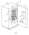
- Figure 1 illustrates schematically a vending machine 1 provided with a door 2 that closes a chamber 3 defined by the walls of a cabinet or outer casing 4.
- the door 2 id in turn provided with an aperture that forms a dispensing site 5 for taking out the beverage prepared by the vending machine 1.
- a selection device 6 of a kind known as such in the art, such as for instance a push-button panel or unit, for buyers to select the beverage they wish to drink.
- This selector device 6 may also integrate means for paying the selected beverage, as they may for instance be constituted by a magnetic card reader or a coin collector.
- the vending machine 1 may of course comprise more than a single dispensing site 5, according to the actual requirements and needs.
- a turret 7 provided with one or more accommodations 8 adapted to receive and hold a corresponding number of stacks 9 of cups.
- the turret 7 is preferably rotating about the longitudinal axis thereof and may be adapted to accommodate and hold differently sized cups through a proper conformation of the accommodations 8.
- These support means 13 are placed on an end section of each accommodation 8 and are preferably connected in an oscillating manner to the turret 7; they are further preferably movable against the action of elastic means.
- These support means 13 may be provided in any number whatsoever, according to the conformation of the turret 7 and the cups.
- a single stack 9 of cups, as arranged within an accommodation 8, and a receptacle 11 with a single compartment 12 have been represented in Figure 1 . It will be readily appreciated, however, that more than just a single stack 9 and just a single compartment 12 may be provided as well.
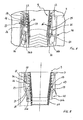
- the vending machine 1 further comprises an arm 14, which, as best illustrated in Figures 2 and 3 , is movable between a first release position, in which the arm 14 lays down a cup 10 into a compartment 12 of the receptacle 11 ( Figure 2 ), and a second gripping position ( Figure 3 ), in which the arm 14 removes a cup 10 from a stack 9 provided within an accommodation 8 of the turret 7.
- the arm 14 is mounted slidably on a runner 15 arranged so that the first cup-release position of the arm comes to be situated in the proximity of the receptacle 11 and the second cup gripping position of the arm lies in the proximity of the first cup 10 of each one of the stacks 9, i.e.
- the runner 15 may be arranged so as to lie in correspondence to the longitudinal axis of rotation of the turret 7.
- the movement of the arm 14 between the above-mentioned first and second positions is imparted by driving means of a kind known as such in the art (and not shown in the Figures).
- the arm14 is further provided with a first jaw 16a and a second jaw 16b, which are movable reciprocally, i.e. relative to each other. This mutual position of the two jaws enables the arm 14 to accommodate different sizes of cups, whereas the same jaws moving apart from each other enable the cup they had previously picked from a stack 9 to be released into a compartment 12 of the receptacle 11.
- Figure 4 illustrates the jaws 16a and 16b of the moving arm 14 and the support means 13 that are associated to the turret 7 in order to enable a cup 10 to be removed and released from a stack 9 of cups.
- the second jaw 16b comprises actuation means 17 that cooperate with the support means 13 to remove a cup 10 from a stack 9 of cups.
- actuation means 17 may be provided either on a single one or both jaws 16a and 16b, depending on the arrangement of the support means 13 on the turret 7; in a preferred manner, they consist of jutting parts.
- At least one of said jaws 16a and 16b comprises at least a moving hook 18 that gets caught between the upper edge 19 of the first cup 10 of a stack 9 and the upper edge 20 of the cup 10' immediately following said first cup 10 in said stack 9 when the arm 14 is in its second gripping position illustrated in Figure 3 .
- their number and arrangement on either the jaw 16a or the jaw 16b, or even both jaws 16a and 16b may be selected so as to for instance most suitably fit a particular shape of the cups.
- Each moving hook 18 comprises a shoe 21 that is so shaped as to be adapted to slide on at least a surface 22 of the turret 7, thereby causing the same hook 18 to displace.
- Each such hook 18 is preferably movable against the action of elastic means.
- the support means 13, which are preferably connected in a swinging manner to the turret 7, comprise a retainer 25 that is so shaped as to be adapted to engage the upper edge 19 of the cup 10.
- the retainer 25, which the latter are provided with is given a cam-like profile 26 for said actuation means 17 to slide thereon.
- the actuation means 17, the support means 13, each hook 18 and the related shoe 21, as well as the surface 22 jointly form a cup release device.
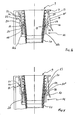
- FIGs 5 , 6 and 7 Three distinct moments in the operation of such cup release device are illustrated in Figures 5 , 6 and 7 .
- the arm 14 is displaced along the runner 15 towards the second gripping position thereof illustrated in Figure 3 .
- the jaws 16a and 16b are suitably spaced apart so as to define a resting surface 23 for the upper edge 19 of the first cup 10 of a stack 9. The extent to which the jaws 16a and 16b are spaced from each other, i.e.
- each hook 18 moves into contact with the surface 22 of the turret 7.
- this surface 22 being preferably constituted by a fork-like structure 27 comprising at least a plane 24 that is inclined relative to the longitudinal axis of the turret 7, the shoe 21 is capable of sliding on this plane 24, thereby driving the hook 18 into moving.
- Each hook 18 is preferably formed by a plate having a first end portion bent in a hook-like manner and a second end portion that is pivotally connected to one of the two jaws 16a, 16b.
- the arm 14 is shown to have reached the position in which it is gripping the first cup 10 of the stack 9.
- the resting surface 23 is in contact with the upper edge 19 of the cup 10 and, under the circumstances, said surface 23 is supporting the entire stack 9 of cups, actually.
- the actuation means 17, by sliding along the cam-like profile 26, have caused the retainer 25 to disengage the upper edge 19 of the first cup 10 of the stack 9.
- the instant at which the retainer 25 releases the edge 19 is substantially the same as the one at which the latter enters into contact with the resting surface 23.
- it is still substantially the same as the instant at which each hook 18 moves in between the upper edge 19 of the first cup 10 and the upper edge 20 of the next cup 10' following said first cup 10 in said stack 9.
- each hook 18 may be constituted by a body that is capable of deflecting under a shear force without any rupture and/or permanent set.
- FIG. 7 Illustrated in Figure 7 is the arm 14 while it moves away from its gripping position upon having removed the cup 10 from the stack 9.
- Each hook 18 exerts a pulling force upon the cup 10, and its being so engaged between the upper edges 19 and 20 of two successive cups 10 and 10' ensures that a single cup at a time is removed from said stack 9.
- the arm 14 moving so away from the gripping position thereof enables the actuation means 17 to leave, i.e. separate from the cam-like profile 26, thereby enabling the retainer 25 to engage the upper edge 20 of the next cup 10' following the one that has just been removed from the stack 9.
- This stack 9 comes in this way to be again supported by the support means 13. Thanks to the particular conformation of the cam-like profile 26, at the very moment at which the cup 10 is removed from the stack 9, the support means 13 are capable of engaging the next cup 10', thereby sustaining again the stack 9 and pegging it in position.
- the shoe 21 moves again into contact with the surface 22, but this time it does so from the opposite side of the inclined plane 24, as compared with the direction of movement shown in Figure 6 .
- the surface 22 is preferably associated to the turret 7 pivotally, so that the same shoe is capable to displace the surface 22 as it slides away from the gripping position.
- Such displacement of the surface 22 caused by the shoe 21 has the sole effect of allowing an unhindered passage of the same shoe 21.
- the fork-like structure 27 of the surface 22 may be constituted by some thin plate that is capable of deflecting under a shear force without any rupture and/or permanent set.
- the arm 14 moves towards the release position thereof in the proximity of the receptacle 11, so as this is illustrated in Figure 2 .
- the opening out of the jaws 16a and 16b as brought about by the same motive means that drive the arm 14 to and from the gripping and release positions thereof, causes the cup 10 to be released and deposited into compartment 12 of said receptacle 11.
- the cup 10 may then be conveyed - in a continuous manner or through a sequence of individual steps - from the receptacle 11 towards any device as may be provided for the preparation of hot or cold beverages, or towards any other device as may be provided to dispense loose edible products requiring being let into a cup prior to being vended out.
- the cup 10, as filled in this way with the desired product or - at most - even empty, will be eventually conveyed towards a delivery or dispensing site 5, which may possibly be common to the one of other dispensing devices comprised in the same vending machine 1, such as for instance a packaged-product dispensing device.
- the present invention can advantageously work with widely varying types of cups, without any replacement of parts being actually required in the vending machine to this purpose.
Landscapes
- Physics & Mathematics (AREA)
- General Physics & Mathematics (AREA)
- Beverage Vending Machines With Cups, And Gas Or Electricity Vending Machines (AREA)
- Table Devices Or Equipment (AREA)
Abstract
Description
- The present invention refers to a beverage vending machine provided with a cup release device.
- Largely known in the art are currently beverage vending machines for dispensing beverages filled into cups, which comprise a movable turret accommodating one or more stacks of cups, as well as devices enabling such cups to be pulled out one at a time, in view to be then filled with a selected beverage. These devices are known to exist in a variety of forms and embodiments. A very simple one among these embodiments is constituted by a pair of spirals arranged at the base of said turret close to the outlet section of a stack of cups, so as to be able to interact with the upper edge of a cup and cause the latter to be released from the stack through a rotation about the coiling axis thereof. However, a device of such kind has a number of drawbacks. One of such drawbacks is for instance due to the fact that the device is not capable of working as efficiently when it is due to release differently sized or shaped cups, or when the clearance or spacing between the upper edges of two successive cups in a stack is not constant. In practice, this may cause two or more stacked cups to be released at the same time, thereby bringing about a situation that may in turn quite easily cause the vending machine to get jammed with a resulting loss in revenues for those who run the vending business.
- A further drawback connected to these devices based on the use of rotating spirals lies in the fact that they make use of the force of gravity for releasing a cup from a stack. In fact, if the stacked cups are provided to already contain the product needed for the preparation of the final beverage, their falling down caused by the action of the spirals entails a partial loss of said products from the cups themselves, so that the resulting spillage scatters all over the vending machine with a diffuse soiling effect.
- Another type of device used to release a cup from a stack is disclosed in the
US patent publication No. 4,327,843 . This device consists of an arm that has its fulcrum on a pivot and is provided of an appropriately shaped end portion cooperating with a kind of jaw to clamp a cup and pull it out of the stack holding it. In this device, the removal of the cup from the stack occurs by exerting a pulling force upon the same cup until the upper edge thereof causes some movable jutting parts that are provided around the outlet section of the compartment accommodating the stack of cups, and which engage said upper edge in order to support the same stack, to open out apart. The cup being so removed from the stack is then dispensed by letting it fall down by gravity upon simply releasing it from the grip of the arm. The cup release device disclosed inUS 4,327,843 shares the same drawback as the afore-described prior-art device concerning the spillage, and resulting scattering inside the vending machine, of the products that may be possibly held in the stacked cups, when the same cups are so removed from the stack for the preparation of the beverage. - A further drawback of this device lies in the fact that the movement of the juts supporting the stack of cups is caused and controlled by the displacement of the cup being removed and this by no means ensures that a single cup is actually removed each time. As a matter of fact, in the case that two successive cups in a stack happen to somehow get or be stuck into each other, the gripping arm would clamp both of them and the juts would be pushed apart by both upper edges of the two cups. In other words, the sole pulling action exerted on the cup to be removed might not prove sufficient to separate from each other two cups that are so stuck into each other, especially if the spacing between the upper edges of such successive cups in a stack is so small that said upper edges come to almost rest against each other.
- Furthermore,
US 6 102 246 discloses a beverage vending machine comprising: a turret for accommodating one or more stacks of cups, support means associated to the turret which cooperate with the first cup in order to support the stack, an arm moving between a release position and a gripping position, and provided with jaws capable of moving relative to each other and a receptacle comprising one or more compartments for receiving cups removed from the stack. - It therefore is the object of the present invention to provide a beverage vending machine, which is provided with a cup release device that does away with the drawbacks of vending machines equipped prior-art cup release devices of the above indicated kind.
- Within this general object, it is a purpose of the present invention to provide a beverage vending machine provided with a cup release device, which is effective in ensuring that a single cup at a time is released from a stack, regardless of the size of such cup, the spacing separating a cup from a successive one in said stack, and the material which the cup is made of.
- Another purpose of the present invention is to provide a beverage vending machine provided with a cup release device, which is effective in preventing possible products contained in each cup of a stack for the preparation of a final beverage from spilling over and scattering inside the vending machine.
- Another purpose yet of the present invention is to provide a beverage vending machine provided with a cup release device, which requires a single drive unit for actuating said device.
- According to the present invention, the above-noted aims are reached in a beverage vending machine provided with a cup release device, which incorporates the features and characteristics as recited in the appended claims.
- Features and advantages of the present invention will anyway be more readily understood from the description that is given below by way of nonlimiting example with reference to the accompanying drawings, in which:
-
Figure 1 is a schematical view of a beverage vending machine according to the present invention, comprising a cup release device; -
Figure 2 is a schematical view of an arm for separating and removing cups from a stack, as shown in a first release position thereof; -
Figure 3 is a schematical view of the arm illustrated inFigure 2 , as shown in a second gripping position thereof; -
Figure 4 is a partially cross-sectional of a cup release device; -
Figure 5 is a cross-sectional view of a cup release device, as shown in a first release phase; -
Figure 6 is a cross-sectional view of a cup release device, as shown in a second release phase; -
Figure 7 is a cross-sectional view of a cup release device, as shown in a third release phase. -
Figure 1 illustrates schematically avending machine 1 provided with adoor 2 that closes achamber 3 defined by the walls of a cabinet or outer casing 4. Thedoor 2 id in turn provided with an aperture that forms a dispensingsite 5 for taking out the beverage prepared by thevending machine 1. On thedoor 2 there is also provided a selection device 6 of a kind known as such in the art, such as for instance a push-button panel or unit, for buyers to select the beverage they wish to drink. This selector device 6 may also integrate means for paying the selected beverage, as they may for instance be constituted by a magnetic card reader or a coin collector. Thevending machine 1 may of course comprise more than asingle dispensing site 5, according to the actual requirements and needs. - Within the
chamber 3 there is arranged aturret 7 provided with one ormore accommodations 8 adapted to receive and hold a corresponding number ofstacks 9 of cups. Theturret 7 is preferably rotating about the longitudinal axis thereof and may be adapted to accommodate and hold differently sized cups through a proper conformation of theaccommodations 8. To theturret 7 there are associated support means 13 cooperating with thefirst cup 10 of eachstack 9 so as to support the entire stack within theaccommodation 8 thereof. These support means 13 are placed on an end section of eachaccommodation 8 and are preferably connected in an oscillating manner to theturret 7; they are further preferably movable against the action of elastic means. These support means 13 may be provided in any number whatsoever, according to the conformation of theturret 7 and the cups. - A
receptacle 11, comprising one ormore compartments 12 adapted to receive the cups being removed from thestacks 9, is adapted to rotate about an axis so as to transfer said cups towards one or moredispensing sites 5. For reasons of greater simplicity, just asingle stack 9 of cups, as arranged within anaccommodation 8, and areceptacle 11 with asingle compartment 12 have been represented inFigure 1 . It will be readily appreciated, however, that more than just asingle stack 9 and just asingle compartment 12 may be provided as well. - The
vending machine 1 further comprises anarm 14, which, as best illustrated inFigures 2 and 3 , is movable between a first release position, in which thearm 14 lays down acup 10 into acompartment 12 of the receptacle 11 (Figure 2 ), and a second gripping position (Figure 3 ), in which thearm 14 removes acup 10 from astack 9 provided within anaccommodation 8 of theturret 7. Thearm 14 is mounted slidably on arunner 15 arranged so that the first cup-release position of the arm comes to be situated in the proximity of thereceptacle 11 and the second cup gripping position of the arm lies in the proximity of thefirst cup 10 of each one of thestacks 9, i.e. thecup 10 that protrudes from theaccommodation 8 in theturret 7. Therunner 15 may be arranged so as to lie in correspondence to the longitudinal axis of rotation of theturret 7. The movement of thearm 14 between the above-mentioned first and second positions is imparted by driving means of a kind known as such in the art (and not shown in the Figures). - The arm14 is further provided with a
first jaw 16a and asecond jaw 16b, which are movable reciprocally, i.e. relative to each other. This mutual position of the two jaws enables thearm 14 to accommodate different sizes of cups, whereas the same jaws moving apart from each other enable the cup they had previously picked from astack 9 to be released into acompartment 12 of thereceptacle 11. -
Figure 4 illustrates thejaws arm 14 and the support means 13 that are associated to theturret 7 in order to enable acup 10 to be removed and released from astack 9 of cups. Thesecond jaw 16b comprises actuation means 17 that cooperate with the support means 13 to remove acup 10 from astack 9 of cups. These actuation means 17 may be provided either on a single one or bothjaws turret 7; in a preferred manner, they consist of jutting parts. In addition, at least one of saidjaws hook 18 that gets caught between theupper edge 19 of thefirst cup 10 of astack 9 and theupper edge 20 of the cup 10' immediately following saidfirst cup 10 in saidstack 9 when thearm 14 is in its second gripping position illustrated inFigure 3 . In the case that more than asingle hook 18 are provided, their number and arrangement on either thejaw 16a or thejaw 16b, or even bothjaws - Each moving
hook 18 comprises ashoe 21 that is so shaped as to be adapted to slide on at least asurface 22 of theturret 7, thereby causing thesame hook 18 to displace. Eachsuch hook 18 is preferably movable against the action of elastic means. - The support means 13, which are preferably connected in a swinging manner to the
turret 7, comprise aretainer 25 that is so shaped as to be adapted to engage theupper edge 19 of thecup 10. For the actuation means 17 to be able to cooperate with these support means 13, theretainer 25, which the latter are provided with, is given a cam-like profile 26 for said actuation means 17 to slide thereon. - The actuation means 17, the support means 13, each
hook 18 and therelated shoe 21, as well as thesurface 22 jointly form a cup release device. - Three distinct moments in the operation of such cup release device are illustrated in
Figures 5 ,6 and 7 . When thevending machine 1 is operated to prepare and dispense a given beverage selected by a buyer, or simply to remove and release a cup from theturret 7, thearm 14 is displaced along therunner 15 towards the second gripping position thereof illustrated inFigure 3 . In this gripping position, thejaws resting surface 23 for theupper edge 19 of thefirst cup 10 of astack 9. The extent to which thejaws surface 23 more appropriately adapted to support cups having differently longupper edges 19. This ensures that thesame arm 14 is able to work in conjunction with cups of widely varying shape and size. - With particular reference to
Figures 4 and 5 , as thearm 14 moves closer to its gripping position, theshoe 21 of eachhook 18 moves into contact with thesurface 22 of theturret 7. Owing to thissurface 22 being preferably constituted by a fork-like structure 27 comprising at least aplane 24 that is inclined relative to the longitudinal axis of theturret 7, theshoe 21 is capable of sliding on thisplane 24, thereby driving thehook 18 into moving. Eachhook 18 is preferably formed by a plate having a first end portion bent in a hook-like manner and a second end portion that is pivotally connected to one of the twojaws shoe 21 with theinclined plane 24, thehook 18 is moved away from thejaws 16a, which it is associated to. During the phase in which thearm 14 moves closer to the gripping position thereof, while eachhook 18 starts to move away from therespective jaws stack 9 of cups. - In the illustration appearing in
Figure 6 , thearm 14 is shown to have reached the position in which it is gripping thefirst cup 10 of thestack 9. The restingsurface 23 is in contact with theupper edge 19 of thecup 10 and, under the circumstances, saidsurface 23 is supporting theentire stack 9 of cups, actually. In fact, the actuation means 17, by sliding along the cam-like profile 26, have caused theretainer 25 to disengage theupper edge 19 of thefirst cup 10 of thestack 9. The instant at which theretainer 25 releases theedge 19 is substantially the same as the one at which the latter enters into contact with the restingsurface 23. Similarly, it is still substantially the same as the instant at which eachhook 18 moves in between theupper edge 19 of thefirst cup 10 and theupper edge 20 of the next cup 10' following saidfirst cup 10 in saidstack 9. - The capability of each
such hook 18 of getting so engaged between the upper edges of two successive cups in a stack is ensured by the fact that, at a moment at which thearm 14 has substantially already moved into the intended gripping position, theshoe 21 leaves thesurface 22 of theturret 7, thereby enabling thehook 18 to move closer to therespective jaw hook 18 moves away from the respective jaw (Figure 5 ), and is then released when theshoe 21 separates from thesurface 22 by passing over the inclined plane 24 (Figure 6 ). As an alternative provision to said elastic means, eachhook 18 may be constituted by a body that is capable of deflecting under a shear force without any rupture and/or permanent set. - Illustrated in
Figure 7 is thearm 14 while it moves away from its gripping position upon having removed thecup 10 from thestack 9. Eachhook 18 exerts a pulling force upon thecup 10, and its being so engaged between theupper edges successive cups 10 and 10' ensures that a single cup at a time is removed from saidstack 9. Thearm 14 moving so away from the gripping position thereof enables the actuation means 17 to leave, i.e. separate from the cam-like profile 26, thereby enabling theretainer 25 to engage theupper edge 20 of the next cup 10' following the one that has just been removed from thestack 9. Thisstack 9 comes in this way to be again supported by the support means 13. Thanks to the particular conformation of the cam-like profile 26, at the very moment at which thecup 10 is removed from thestack 9, the support means 13 are capable of engaging the next cup 10', thereby sustaining again thestack 9 and pegging it in position. - The
shoe 21 moves again into contact with thesurface 22, but this time it does so from the opposite side of theinclined plane 24, as compared with the direction of movement shown inFigure 6 . In view of preventing the movement of theshoe 21 from being hindered, or made anyhow difficult, thesurface 22 is preferably associated to theturret 7 pivotally, so that the same shoe is capable to displace thesurface 22 as it slides away from the gripping position. Such displacement of thesurface 22 caused by theshoe 21 has the sole effect of allowing an unhindered passage of thesame shoe 21. As an alternative provision, the fork-like structure 27 of thesurface 22 may be constituted by some thin plate that is capable of deflecting under a shear force without any rupture and/or permanent set. - Upon the
cup 10 having so been removed from thestack 9, thearm 14 moves towards the release position thereof in the proximity of thereceptacle 11, so as this is illustrated inFigure 2 . The opening out of thejaws arm 14 to and from the gripping and release positions thereof, causes thecup 10 to be released and deposited intocompartment 12 of saidreceptacle 11. If required, thecup 10 may then be conveyed - in a continuous manner or through a sequence of individual steps - from thereceptacle 11 towards any device as may be provided for the preparation of hot or cold beverages, or towards any other device as may be provided to dispense loose edible products requiring being let into a cup prior to being vended out. Thecup 10, as filled in this way with the desired product or - at most - even empty, will be eventually conveyed towards a delivery or dispensingsite 5, which may possibly be common to the one of other dispensing devices comprised in thesame vending machine 1, such as for instance a packaged-product dispensing device. - Fully apparent from the above description is therefore the ability of the the present invention to effectively reach the afore cited aims and advantages by providing a beverage vending machine with a cup release device that is effective in ensuring that just a single cup at a time is removed from a stack of cups, thereby avoiding any blocking-up problem of the vending machine. Fully apparent is also the capability of the present invention of enabling a cup to be trasnferred in a controlled manner from the place in which it is stocked to the place in which the porduct to be dispensed is prepared, thereby preventing any product that may be possibly present in the cup itself from spilling out.
- In addition, the present invention can advantageously work with widely varying types of cups, without any replacement of parts being actually required in the vending machine to this purpose.
- It will be readily appreciated that the materials used, as well as the shapes and the sizing of the individual items, may each time be selected so as to more appropriately meet the particular requirements or suit the particular application, without departing from the scope of the present invention.
- It will also be readily appreciated that the various elements constituting the present invention shall not necessarily be embodied in the sole forms as described above and illustrated with reference to the accompanying drawings, but may be embodied in a number of different forms, and be subject to a number of modifications and variants, without departing from the scope of the present invention.
Claims (16)
- A beverage vending machine (1) comprising:- a turret (7) for accommodating one or more stacks (9) of cups;- support means associated to said turret (7) and provided with a retainer (25), which engages the first cup (10) of each one of said stacks (9) to support them in said turret (7);- an arm (14) moving between a first release position and a second gripping position, and provided with a first jaw (16a) and a second jaw (16b) capable of moving relative to each other;- a receptacle (11) comprising one or more compartments (12) for receiving one or more of such cups removed from said stacks (9),characterized in that at least one of said first and second jaws (16a, 16b) comprises actuating means (17) that slide along a cam-like profile (26) of said retainer (25) to cause said retainer (25) to disengage a first cup (10) of one of said stacks (9) and to enable said first cup(10) to be removed from said one of said stacks (9), and comprises at least a movable hook (18) adapted to get engaged between the upper edge (19) of said first cup (10) in said one of said stacks (9) and the upper edge (20) of the next cup (10') following said first cup (10) in the same stack (9) when said arm (14) is in said second gripping position, the hook (18) being further adapted to exert a pulling force upon said first cup (10) when said arm (14) moves away from said second gripping position.
- The beverage vending machine (1) according to claim 1, wherein said actuation means (17) are constituted by jutting parts.
- The beverage vending machine (1) according to claim 1, wherein said at least a hook (18) comprises a shoe (21) adapted to slide on at least a surface (22) of said turret (7) to drive said hook (18) into moving.
- The beverage vending machine (1) according to claim 3, wherein said at least a surface (22) is formed by a fork (27) comprising at least a plane (24) that is inclined relative to the longitudinal axis of said turret (7).
- The beverage vending machine (1) according to claim 3 or 4, wherein said at least a surface (22) is associated with said turret (7) in a pivotally swinging manner.
- The beverage vending machine (1) according to claim 3, wherein said fork (27) is constituted by a thin flexible strip.
- The beverage vending machine (1) according to any of the preceding claims, wherein said at least a hook (18) is constituted by a small plate having a first end portion bent in a hook-like manner and a second end portion that is connected to one of said jaws (16a, 16b) in a pivotally swinging manner.
- The beverage vending machine (1) according to any of the preceding claims, wherein said at least a hook (18) is movable against the action of elastic means.
- The beverage vending machine (1) according to any of the preceding claims 1 to 7, wherein said at least a hook (18) is constituted by a flexible body.
- The beverage vending machine (1) according to any of the preceding claims, wherein said support means (13) are connected in a pivotally swinging manner to said turret (7).
- The beverage vending machine (1) according to claim 10, wherein said support means (13) are movable against the action of elastic means.
- The beverage vending machine (1) according to any of the preceding claims, wherein said first and second jaws (16a, 16b) define, when in said gripping position, a resting surface (13) for the upper edge (19) of said first cup (10) in one of said stacks (9) to rest upon.
- The beverage vending machine (1) according to claim 12, further comprising a device for the adjustment of the position of said jaws (16a, 16b) relative to each other in view of adapting said resting surface (23) to support cups having differently long upper edges (19,20).
- The beverage vending machine (1) according to any of the preceding claims, wherein said receptacle (11) is movable to convey said one or more cups removed from said stacks (9) into one or more dispensing sites (5).
- The beverage vending machine (1) according to any of the preceding claims, wherein said arm (14) is mounted slidably on a runner (15) arranged so that said first cup-release position comes to be situated in the proximity of said receptacle (11) and said second cup gripping position lies in the proximity of said first cup (10) of each one of the stacks (9).
- The beverage vending machine (1) according to any of the preceding claims, wherein said turret (7) is adapted to accommodate stacks (9) of variously sized cups.
Applications Claiming Priority (2)
| Application Number | Priority Date | Filing Date | Title |
|---|---|---|---|
| IT000008A ITPN20040008A1 (en) | 2004-02-09 | 2004-02-09 | AUTOMATIC BEVERAGE DISPENSER WITH GLASS RELEASE DEVICE |
| PCT/EP2005/050160 WO2005076235A1 (en) | 2004-02-09 | 2005-01-17 | Beverage vending machine with cup release device |
Publications (2)
| Publication Number | Publication Date |
|---|---|
| EP1716546A1 EP1716546A1 (en) | 2006-11-02 |
| EP1716546B1 true EP1716546B1 (en) | 2010-10-20 |
Family
ID=34835607
Family Applications (1)
| Application Number | Title | Priority Date | Filing Date |
|---|---|---|---|
| EP05707784A Not-in-force EP1716546B1 (en) | 2004-02-09 | 2005-01-17 | Beverage vending machine with cup release device |
Country Status (9)
| Country | Link |
|---|---|
| EP (1) | EP1716546B1 (en) |
| JP (1) | JP4833863B2 (en) |
| CN (1) | CN100565598C (en) |
| AT (1) | ATE485575T1 (en) |
| DE (1) | DE602005024236D1 (en) |
| DK (1) | DK1716546T3 (en) |
| ES (1) | ES2353523T3 (en) |
| IT (1) | ITPN20040008A1 (en) |
| WO (1) | WO2005076235A1 (en) |
Families Citing this family (12)
| Publication number | Priority date | Publication date | Assignee | Title |
|---|---|---|---|---|
| IT1403912B1 (en) * | 2011-02-04 | 2013-11-08 | Poleni | AUTOMATIC DISTRIBUTOR OF FOOD AND PRODUCTS IN GENERAL |
| CA2846821A1 (en) * | 2011-08-26 | 2013-03-07 | Crane Merchandising Systems, Inc. | Planetary gear drive cup turret for cup drop unit in beverage vending machine |
| DE102012207665B4 (en) * | 2012-05-08 | 2017-02-09 | Sielaff Gmbh & Co. Kg Automatenbau | Vending machine, method for operating a vending machine |
| FR3035731B1 (en) * | 2015-04-28 | 2017-05-05 | Photo-Me Int Plc | DEVICE FOR STORING AND DISTRIBUTING CONSUMABLES |
| IT201600124688A1 (en) * | 2016-12-09 | 2018-06-09 | Ilventitre S R L | "DEVICE FOR THE PREPARATION AND DELIVERY OF A CONE OR ICE CREAM CUP" |
| IT201700043567A1 (en) * | 2017-04-20 | 2018-10-20 | N&W Global Vending S P A | DISPOSABLE CONTAINER DISTRIBUTOR FOR DRINK PREPARATION |
| CN107578546A (en) * | 2017-09-26 | 2018-01-12 | 谢启浩 | Shared water dispenser |
| ES2822097T3 (en) * | 2017-10-19 | 2021-04-29 | Evoca Spa | Device for dispensing items from a stack of nested items, in particular tumbler lids |
| CN107833390A (en) * | 2017-12-12 | 2018-03-23 | 刘伟利 | A kind of ice cream vending machine |
| IT201900020940A1 (en) * | 2019-11-12 | 2021-05-12 | Evoca Spa | CUPS DISPENSING UNIT FOR A VENDING BEVERAGE DISTRIBUTOR |
| CN111012178B (en) * | 2019-12-20 | 2022-01-25 | 北京怡盛原环保科技有限公司 | Wall-hanging water purifier of portable |
| KR102463345B1 (en) * | 2021-01-26 | 2022-11-04 | 김완수 | Automatic capsule beverage device |
Family Cites Families (11)
| Publication number | Priority date | Publication date | Assignee | Title |
|---|---|---|---|---|
| US4327843A (en) * | 1980-05-27 | 1982-05-04 | Corley Dewey A | Cup dispensing mechanism |
| GB2145071B (en) * | 1983-08-18 | 1986-06-18 | Peter Dixon Jones | Cup and like dispenser |
| FR2625888A1 (en) * | 1988-01-20 | 1989-07-21 | App Automatiques Ste Indle | DEVICE FOR DISPENSING STACKED CUPS |
| JPH03276296A (en) * | 1990-03-26 | 1991-12-06 | Sanyo Electric Co Ltd | Cup holding device of cup type automatic vending machine |
| JP3243918B2 (en) * | 1994-02-23 | 2002-01-07 | 富士電機株式会社 | Control device for cup mixing vending machine |
| EP0704376A1 (en) * | 1994-09-30 | 1996-04-03 | Grapha-Holding Ag | Method for preparing containers fed to a storing device |
| JPH11161844A (en) * | 1997-11-28 | 1999-06-18 | Kokoro:Kk | Heat cooking type automatic vending machine |
| US6053359A (en) * | 1997-12-22 | 2000-04-25 | Mcdonald's Corporation | Automated beverage system |
| IT1304276B1 (en) * | 1998-04-15 | 2001-03-13 | Ducale Macchine Da Caffe Di Sa | AUTOMATIC BEVERAGE DISPENSER IN GLASS. |
| ITPN20000024A1 (en) * | 2000-04-20 | 2001-10-20 | Necta Vending Solutions Spa | AUTOMATIC BEVERAGE DISPENSER WITH PERFECTED GLASS RELEASE MECHANISM |
| JP2003196734A (en) * | 2001-12-26 | 2003-07-11 | Toshiba Electric Appliance Co Ltd | Device for supplying cup |
-
2004
- 2004-02-09 IT IT000008A patent/ITPN20040008A1/en unknown
-
2005
- 2005-01-17 JP JP2006551832A patent/JP4833863B2/en not_active Expired - Fee Related
- 2005-01-17 ES ES05707784T patent/ES2353523T3/en active Active
- 2005-01-17 EP EP05707784A patent/EP1716546B1/en not_active Not-in-force
- 2005-01-17 DE DE602005024236T patent/DE602005024236D1/en active Active
- 2005-01-17 CN CNB2005800002805A patent/CN100565598C/en not_active Expired - Fee Related
- 2005-01-17 AT AT05707784T patent/ATE485575T1/en active
- 2005-01-17 DK DK05707784.4T patent/DK1716546T3/en active
- 2005-01-17 WO PCT/EP2005/050160 patent/WO2005076235A1/en not_active Application Discontinuation
Also Published As
| Publication number | Publication date |
|---|---|
| EP1716546A1 (en) | 2006-11-02 |
| ES2353523T3 (en) | 2011-03-02 |
| CN100565598C (en) | 2009-12-02 |
| ATE485575T1 (en) | 2010-11-15 |
| DK1716546T3 (en) | 2011-01-24 |
| JP2007525751A (en) | 2007-09-06 |
| WO2005076235A1 (en) | 2005-08-18 |
| ITPN20040008A1 (en) | 2004-05-09 |
| JP4833863B2 (en) | 2011-12-07 |
| DE602005024236D1 (en) | 2010-12-02 |
| CN1771520A (en) | 2006-05-10 |
Similar Documents
| Publication | Publication Date | Title |
|---|---|---|
| EP1716546B1 (en) | Beverage vending machine with cup release device | |
| EP3128874B1 (en) | Forward advancing cutlery dispenser | |
| US7900797B1 (en) | Lid separator and dispensing device | |
| EP2082379B1 (en) | Automatic product vending machine | |
| US4591070A (en) | Article dispenser adjustable for different size articles | |
| DE60309873T2 (en) | DEVICE AND METHOD FOR SELLING PRODUCTS IN DIFFERENT SIZES | |
| JP3770406B2 (en) | Vending machine for choosing pack mixing | |
| US3737071A (en) | Product dispensing apparatus | |
| US4779760A (en) | Article release mechanism | |
| CN102084402B (en) | Method of dispensing products off a vending machine tray | |
| NL194351C (en) | Column dispenser for releasing products. | |
| US2875877A (en) | Vending machines | |
| US3554364A (en) | Control and cup-pushing assembly for dispensers | |
| EP3129961B1 (en) | Vending machines | |
| US4327843A (en) | Cup dispensing mechanism | |
| US3765566A (en) | Vending machine product distributor | |
| US9251640B2 (en) | Horizontal lid dispenser | |
| US3180518A (en) | Mechanical vendor for articles | |
| US20020092861A1 (en) | Magazine vending machine | |
| RU66739U1 (en) | DEVICE FOR RETAINING AND DELIVERY OF GOODS IN A TRADE AUTOMATIC OR SEMI-AUTOMATIC | |
| EP2443972A1 (en) | System for feeding capsules containing a food product for producing a beverage or the like, particularly for vending machines | |
| EP1107201A2 (en) | Automatic beverage vending apparatus with improved arrangement for displacing the dispensing spouts | |
| DE917879C (en) | Cup dispenser, e.g. for beverage machines | |
| US1502325A (en) | Sandwich dispenser | |
| NO325377B1 (en) | System and method of storage and delivery of product units |
Legal Events
| Date | Code | Title | Description |
|---|---|---|---|
| PUAI | Public reference made under article 153(3) epc to a published international application that has entered the european phase |
Free format text: ORIGINAL CODE: 0009012 |
|
| 17P | Request for examination filed |
Effective date: 20060911 |
|
| AK | Designated contracting states |
Kind code of ref document: A1 Designated state(s): AT BE BG CH CY CZ DE DK EE ES FI FR GB GR HU IE IS IT LI LT LU MC NL PL PT RO SE SI SK TR |
|
| DAX | Request for extension of the european patent (deleted) | ||
| GRAP | Despatch of communication of intention to grant a patent |
Free format text: ORIGINAL CODE: EPIDOSNIGR1 |
|
| GRAS | Grant fee paid |
Free format text: ORIGINAL CODE: EPIDOSNIGR3 |
|
| GRAA | (expected) grant |
Free format text: ORIGINAL CODE: 0009210 |
|
| RIN1 | Information on inventor provided before grant (corrected) |
Inventor name: JOHNDROW, JOHN PAUL17 FERNDALE ROAD |
|
| AK | Designated contracting states |
Kind code of ref document: B1 Designated state(s): AT BE BG CH CY CZ DE DK EE ES FI FR GB GR HU IE IS IT LI LT LU MC NL PL PT RO SE SI SK TR |
|
| REG | Reference to a national code |
Ref country code: GB Ref legal event code: FG4D |
|
| REG | Reference to a national code |
Ref country code: CH Ref legal event code: EP |
|
| GRAL | Information related to payment of fee for publishing/printing deleted |
Free format text: ORIGINAL CODE: EPIDOSDIGR3 |
|
| GRAS | Grant fee paid |
Free format text: ORIGINAL CODE: EPIDOSNIGR3 |
|
| REG | Reference to a national code |
Ref country code: IE Ref legal event code: FG4D |
|
| REF | Corresponds to: |
Ref document number: 602005024236 Country of ref document: DE Date of ref document: 20101202 Kind code of ref document: P |
|
| REG | Reference to a national code |
Ref country code: DK Ref legal event code: T3 |
|
| REG | Reference to a national code |
Ref country code: CH Ref legal event code: NV Representative=s name: HEPP WENGER RYFFEL AG |
|
| REG | Reference to a national code |
Ref country code: NL Ref legal event code: T3 |
|
| REG | Reference to a national code |
Ref country code: ES Ref legal event code: FG2A Effective date: 20110218 |
|
| LTIE | Lt: invalidation of european patent or patent extension |
Effective date: 20101020 |
|
| PG25 | Lapsed in a contracting state [announced via postgrant information from national office to epo] |
Ref country code: LT Free format text: LAPSE BECAUSE OF FAILURE TO SUBMIT A TRANSLATION OF THE DESCRIPTION OR TO PAY THE FEE WITHIN THE PRESCRIBED TIME-LIMIT Effective date: 20101020 |
|
| PG25 | Lapsed in a contracting state [announced via postgrant information from national office to epo] |
Ref country code: FI Free format text: LAPSE BECAUSE OF FAILURE TO SUBMIT A TRANSLATION OF THE DESCRIPTION OR TO PAY THE FEE WITHIN THE PRESCRIBED TIME-LIMIT Effective date: 20101020 Ref country code: IS Free format text: LAPSE BECAUSE OF FAILURE TO SUBMIT A TRANSLATION OF THE DESCRIPTION OR TO PAY THE FEE WITHIN THE PRESCRIBED TIME-LIMIT Effective date: 20110220 Ref country code: SE Free format text: LAPSE BECAUSE OF FAILURE TO SUBMIT A TRANSLATION OF THE DESCRIPTION OR TO PAY THE FEE WITHIN THE PRESCRIBED TIME-LIMIT Effective date: 20101020 Ref country code: SI Free format text: LAPSE BECAUSE OF FAILURE TO SUBMIT A TRANSLATION OF THE DESCRIPTION OR TO PAY THE FEE WITHIN THE PRESCRIBED TIME-LIMIT Effective date: 20101020 Ref country code: PT Free format text: LAPSE BECAUSE OF FAILURE TO SUBMIT A TRANSLATION OF THE DESCRIPTION OR TO PAY THE FEE WITHIN THE PRESCRIBED TIME-LIMIT Effective date: 20110221 Ref country code: BG Free format text: LAPSE BECAUSE OF FAILURE TO SUBMIT A TRANSLATION OF THE DESCRIPTION OR TO PAY THE FEE WITHIN THE PRESCRIBED TIME-LIMIT Effective date: 20110120 |
|
| PG25 | Lapsed in a contracting state [announced via postgrant information from national office to epo] |
Ref country code: GR Free format text: LAPSE BECAUSE OF FAILURE TO SUBMIT A TRANSLATION OF THE DESCRIPTION OR TO PAY THE FEE WITHIN THE PRESCRIBED TIME-LIMIT Effective date: 20110121 |
|
| PG25 | Lapsed in a contracting state [announced via postgrant information from national office to epo] |
Ref country code: CZ Free format text: LAPSE BECAUSE OF FAILURE TO SUBMIT A TRANSLATION OF THE DESCRIPTION OR TO PAY THE FEE WITHIN THE PRESCRIBED TIME-LIMIT Effective date: 20101020 Ref country code: EE Free format text: LAPSE BECAUSE OF FAILURE TO SUBMIT A TRANSLATION OF THE DESCRIPTION OR TO PAY THE FEE WITHIN THE PRESCRIBED TIME-LIMIT Effective date: 20101020 |
|
| PLBE | No opposition filed within time limit |
Free format text: ORIGINAL CODE: 0009261 |
|
| STAA | Information on the status of an ep patent application or granted ep patent |
Free format text: STATUS: NO OPPOSITION FILED WITHIN TIME LIMIT |
|
| PG25 | Lapsed in a contracting state [announced via postgrant information from national office to epo] |
Ref country code: PL Free format text: LAPSE BECAUSE OF FAILURE TO SUBMIT A TRANSLATION OF THE DESCRIPTION OR TO PAY THE FEE WITHIN THE PRESCRIBED TIME-LIMIT Effective date: 20101020 Ref country code: MC Free format text: LAPSE BECAUSE OF NON-PAYMENT OF DUE FEES Effective date: 20110131 Ref country code: RO Free format text: LAPSE BECAUSE OF FAILURE TO SUBMIT A TRANSLATION OF THE DESCRIPTION OR TO PAY THE FEE WITHIN THE PRESCRIBED TIME-LIMIT Effective date: 20101020 Ref country code: SK Free format text: LAPSE BECAUSE OF FAILURE TO SUBMIT A TRANSLATION OF THE DESCRIPTION OR TO PAY THE FEE WITHIN THE PRESCRIBED TIME-LIMIT Effective date: 20101020 |
|
| 26N | No opposition filed |
Effective date: 20110721 |
|
| REG | Reference to a national code |
Ref country code: IE Ref legal event code: MM4A |
|
| REG | Reference to a national code |
Ref country code: DE Ref legal event code: R097 Ref document number: 602005024236 Country of ref document: DE Effective date: 20110721 |
|
| PG25 | Lapsed in a contracting state [announced via postgrant information from national office to epo] |
Ref country code: IE Free format text: LAPSE BECAUSE OF NON-PAYMENT OF DUE FEES Effective date: 20110117 |
|
| PGFP | Annual fee paid to national office [announced via postgrant information from national office to epo] |
Ref country code: CH Payment date: 20120112 Year of fee payment: 8 |
|
| PGFP | Annual fee paid to national office [announced via postgrant information from national office to epo] |
Ref country code: BE Payment date: 20120117 Year of fee payment: 8 Ref country code: GB Payment date: 20120111 Year of fee payment: 8 Ref country code: DK Payment date: 20120111 Year of fee payment: 8 |
|
| PGFP | Annual fee paid to national office [announced via postgrant information from national office to epo] |
Ref country code: AT Payment date: 20120110 Year of fee payment: 8 |
|
| PG25 | Lapsed in a contracting state [announced via postgrant information from national office to epo] |
Ref country code: CY Free format text: LAPSE BECAUSE OF FAILURE TO SUBMIT A TRANSLATION OF THE DESCRIPTION OR TO PAY THE FEE WITHIN THE PRESCRIBED TIME-LIMIT Effective date: 20101020 Ref country code: LU Free format text: LAPSE BECAUSE OF NON-PAYMENT OF DUE FEES Effective date: 20110117 |
|
| BERE | Be: lapsed |
Owner name: N&W GLOBAL VENDING S.P.A. Effective date: 20130131 |
|
| REG | Reference to a national code |
Ref country code: DK Ref legal event code: EBP |
|
| REG | Reference to a national code |
Ref country code: CH Ref legal event code: PL |
|
| REG | Reference to a national code |
Ref country code: AT Ref legal event code: MM01 Ref document number: 485575 Country of ref document: AT Kind code of ref document: T Effective date: 20130131 |
|
| GBPC | Gb: european patent ceased through non-payment of renewal fee |
Effective date: 20130117 |
|
| PG25 | Lapsed in a contracting state [announced via postgrant information from national office to epo] |
Ref country code: TR Free format text: LAPSE BECAUSE OF FAILURE TO SUBMIT A TRANSLATION OF THE DESCRIPTION OR TO PAY THE FEE WITHIN THE PRESCRIBED TIME-LIMIT Effective date: 20101020 |
|
| PG25 | Lapsed in a contracting state [announced via postgrant information from national office to epo] |
Ref country code: LI Free format text: LAPSE BECAUSE OF NON-PAYMENT OF DUE FEES Effective date: 20130131 Ref country code: AT Free format text: LAPSE BECAUSE OF NON-PAYMENT OF DUE FEES Effective date: 20130131 Ref country code: BE Free format text: LAPSE BECAUSE OF NON-PAYMENT OF DUE FEES Effective date: 20130131 Ref country code: HU Free format text: LAPSE BECAUSE OF FAILURE TO SUBMIT A TRANSLATION OF THE DESCRIPTION OR TO PAY THE FEE WITHIN THE PRESCRIBED TIME-LIMIT Effective date: 20101020 Ref country code: CH Free format text: LAPSE BECAUSE OF NON-PAYMENT OF DUE FEES Effective date: 20130131 |
|
| PG25 | Lapsed in a contracting state [announced via postgrant information from national office to epo] |
Ref country code: GB Free format text: LAPSE BECAUSE OF NON-PAYMENT OF DUE FEES Effective date: 20130117 |
|
| PG25 | Lapsed in a contracting state [announced via postgrant information from national office to epo] |
Ref country code: DK Free format text: LAPSE BECAUSE OF NON-PAYMENT OF DUE FEES Effective date: 20130131 |
|
| REG | Reference to a national code |
Ref country code: DE Ref legal event code: R082 Ref document number: 602005024236 Country of ref document: DE Representative=s name: BOCKHORNI & KOLLEGEN PATENT- UND RECHTSANWAELT, DE Ref country code: DE Ref legal event code: R082 Ref document number: 602005024236 Country of ref document: DE Representative=s name: HEYER, VOLKER, DIPL.-PHYS. DR.RER.NAT., DE |
|
| REG | Reference to a national code |
Ref country code: DE Ref legal event code: R082 Ref document number: 602005024236 Country of ref document: DE Representative=s name: HEYER, VOLKER, DIPL.-PHYS. DR.RER.NAT., DE |
|
| REG | Reference to a national code |
Ref country code: FR Ref legal event code: PLFP Year of fee payment: 12 |
|
| REG | Reference to a national code |
Ref country code: FR Ref legal event code: PLFP Year of fee payment: 13 |
|
| REG | Reference to a national code |
Ref country code: FR Ref legal event code: PLFP Year of fee payment: 14 |
|
| PGFP | Annual fee paid to national office [announced via postgrant information from national office to epo] |
Ref country code: ES Payment date: 20190225 Year of fee payment: 15 Ref country code: FR Payment date: 20190128 Year of fee payment: 15 |
|
| PGFP | Annual fee paid to national office [announced via postgrant information from national office to epo] |
Ref country code: DE Payment date: 20190401 Year of fee payment: 15 |
|
| REG | Reference to a national code |
Ref country code: DE Ref legal event code: R119 Ref document number: 602005024236 Country of ref document: DE |
|
| REG | Reference to a national code |
Ref country code: NL Ref legal event code: MM Effective date: 20200201 |
|
| PG25 | Lapsed in a contracting state [announced via postgrant information from national office to epo] |
Ref country code: NL Free format text: LAPSE BECAUSE OF NON-PAYMENT OF DUE FEES Effective date: 20200201 Ref country code: DE Free format text: LAPSE BECAUSE OF NON-PAYMENT OF DUE FEES Effective date: 20200801 |
|
| PGFP | Annual fee paid to national office [announced via postgrant information from national office to epo] |
Ref country code: IT Payment date: 20210105 Year of fee payment: 17 |
|
| REG | Reference to a national code |
Ref country code: ES Ref legal event code: FD2A Effective date: 20210603 |
|
| PG25 | Lapsed in a contracting state [announced via postgrant information from national office to epo] |
Ref country code: FR Free format text: LAPSE BECAUSE OF NON-PAYMENT OF DUE FEES Effective date: 20200131 |
|
| PG25 | Lapsed in a contracting state [announced via postgrant information from national office to epo] |
Ref country code: ES Free format text: LAPSE BECAUSE OF NON-PAYMENT OF DUE FEES Effective date: 20200118 |
|
| PG25 | Lapsed in a contracting state [announced via postgrant information from national office to epo] |
Ref country code: IT Free format text: LAPSE BECAUSE OF NON-PAYMENT OF DUE FEES Effective date: 20220117 |