EP1714826B1 - Gestell und Fahrzeugsitz mit einem solchen Gestell für Kinder - Google Patents
Gestell und Fahrzeugsitz mit einem solchen Gestell für Kinder Download PDFInfo
- Publication number
- EP1714826B1 EP1714826B1 EP06075833A EP06075833A EP1714826B1 EP 1714826 B1 EP1714826 B1 EP 1714826B1 EP 06075833 A EP06075833 A EP 06075833A EP 06075833 A EP06075833 A EP 06075833A EP 1714826 B1 EP1714826 B1 EP 1714826B1
- Authority
- EP
- European Patent Office
- Prior art keywords
- chassis
- slide
- connectors
- securing elements
- frame
- Prior art date
- Legal status (The legal status is an assumption and is not a legal conclusion. Google has not performed a legal analysis and makes no representation as to the accuracy of the status listed.)
- Not-in-force
Links
Images


Classifications
-
- B—PERFORMING OPERATIONS; TRANSPORTING
- B60—VEHICLES IN GENERAL
- B60N—SEATS SPECIALLY ADAPTED FOR VEHICLES; VEHICLE PASSENGER ACCOMMODATION NOT OTHERWISE PROVIDED FOR
- B60N2/00—Seats specially adapted for vehicles; Arrangement or mounting of seats in vehicles
- B60N2/24—Seats specially adapted for vehicles; Arrangement or mounting of seats in vehicles for particular purposes or particular vehicles
- B60N2/26—Seats specially adapted for vehicles; Arrangement or mounting of seats in vehicles for particular purposes or particular vehicles for children
- B60N2/28—Seats readily mountable on, and dismountable from, existing seats or other parts of the vehicle
- B60N2/2821—Seats readily mountable on, and dismountable from, existing seats or other parts of the vehicle having a seat and a base part
- B60N2/2824—Seats readily mountable on, and dismountable from, existing seats or other parts of the vehicle having a seat and a base part part of the base being supported by the vehicle frame
-
- B—PERFORMING OPERATIONS; TRANSPORTING
- B60—VEHICLES IN GENERAL
- B60N—SEATS SPECIALLY ADAPTED FOR VEHICLES; VEHICLE PASSENGER ACCOMMODATION NOT OTHERWISE PROVIDED FOR
- B60N2/00—Seats specially adapted for vehicles; Arrangement or mounting of seats in vehicles
- B60N2/24—Seats specially adapted for vehicles; Arrangement or mounting of seats in vehicles for particular purposes or particular vehicles
- B60N2/26—Seats specially adapted for vehicles; Arrangement or mounting of seats in vehicles for particular purposes or particular vehicles for children
- B60N2/28—Seats readily mountable on, and dismountable from, existing seats or other parts of the vehicle
- B60N2/2887—Fixation to a transversal anchorage bar, e.g. isofix
- B60N2/2893—Fixation to a transversal anchorage bar, e.g. isofix coupled to the seat sub-frame
-
- B—PERFORMING OPERATIONS; TRANSPORTING
- B60—VEHICLES IN GENERAL
- B60N—SEATS SPECIALLY ADAPTED FOR VEHICLES; VEHICLE PASSENGER ACCOMMODATION NOT OTHERWISE PROVIDED FOR
- B60N2/00—Seats specially adapted for vehicles; Arrangement or mounting of seats in vehicles
- B60N2/24—Seats specially adapted for vehicles; Arrangement or mounting of seats in vehicles for particular purposes or particular vehicles
- B60N2/26—Seats specially adapted for vehicles; Arrangement or mounting of seats in vehicles for particular purposes or particular vehicles for children
- B60N2/28—Seats readily mountable on, and dismountable from, existing seats or other parts of the vehicle
- B60N2/2857—Seats readily mountable on, and dismountable from, existing seats or other parts of the vehicle characterised by the peculiar orientation of the child
- B60N2/286—Seats readily mountable on, and dismountable from, existing seats or other parts of the vehicle characterised by the peculiar orientation of the child forward facing
-
- B—PERFORMING OPERATIONS; TRANSPORTING
- B60—VEHICLES IN GENERAL
- B60N—SEATS SPECIALLY ADAPTED FOR VEHICLES; VEHICLE PASSENGER ACCOMMODATION NOT OTHERWISE PROVIDED FOR
- B60N2/00—Seats specially adapted for vehicles; Arrangement or mounting of seats in vehicles
- B60N2/24—Seats specially adapted for vehicles; Arrangement or mounting of seats in vehicles for particular purposes or particular vehicles
- B60N2/26—Seats specially adapted for vehicles; Arrangement or mounting of seats in vehicles for particular purposes or particular vehicles for children
- B60N2/28—Seats readily mountable on, and dismountable from, existing seats or other parts of the vehicle
- B60N2/2887—Fixation to a transversal anchorage bar, e.g. isofix
Definitions
- the invention relates to a chassis suitable for supporting a child vehicle seat, which chassis is provided with a frame comprising at least one connector, which connector can be detachably connected in use to at least one securing element present in a vehicle, which chassis is further provided with an unlocking mechanism for releasing the engagement between the connector and the securing element, as well as with a slide for supporting the child vehicle seat, which slide is movable with respect to the frame in the position in which the connector is connected to the securing element, from a first position, in which the slide is positioned at a relatively large distance from the connector, to a second position, in which the slide is positioned closer to the connector, and vice versa, with the slide being locked against movement from the second position to the first position when the connector is connected to the securing element.
- the invention also relates to a child vehicle seat provided with such a chassis.
- each connector is moved to a fully extended position before the child vehicle seat is secured in the vehicle. In this first position, movement to the second position is not possible.
- a connector is connected to the associated securing element, it is possible to move the slide with respect to the frame on the side of the connector in question. If the other connector is not connected to the associated securing element yet, movement of the slide with respect to the frame is not possible on the side of that connector. If the user attempts to connect the child vehicle seat to the associated securing element by exerting a relatively large force, there is a risk that the slide will partially move with respect to the frame already, which will result in damage to child vehicle seat.
- the object of the invention is to provide a chassis as well as a child vehicle seat provided with such a chassis in which the slide cannot be moved undesirably with respect to the frame.
- the slide In the first position, the slide is positioned at a relatively large distance from the connector, so that it is relatively easy to connect the connector to the securing elements that are present in the vehicle.
- the slide cannot move with respect to the connectors whilst said connection is being effected, thereby enabling a user to take a firm hold of the slide or of the child vehicle seat that is connected thereto and expert the required force thereon for connecting the connectors to the securing elements.
- the slide can be moved in the direction of the connector together with the child vehicle seat that is supported by said slide, for example until the child vehicle seat abuts against the back support of the vehicle seat.
- the slide In the position in which the connector is connected to the securing element, the slide is locked against movement back to the first position, so that the slide and the child vehicle seat that is supported thereby cannot be undesirably moved in a direction away from the connector, for example in case of a collision.
- a user who is placing the chassis in a vehicle can easily determine from the fact that the slide can be moved freely from the second position to the first position that not all the connectors are connected to the securing elements. This is necessary, however, in order to ensure a reliable connection between the chassis and the vehicle.
- a user who is fitting the chassis in the vehicle can determine that not all the connectors are connected to the associated securing elements from the fact that movement of the slide towards the connectors is not possible.
- All the connectors need to be connected to the associated securing elements in order to ensure a secure engagement between the chassis and the vehicle.
- One embodiment of the chassis according to the invention is characterized in that all the connectors are connected to the common unlocking mechanism which, when operated, allows movement of the slide from the second position to the first position.
- the connectors are disconnected by operating the unlocking mechanism.
- Operating the unlocking mechanism also makes it possible for the slide to be moved from the second position to the first position just before, during or after said disconnecting of the connectors.
- the slide can be moved to the desired first position again in that case, so that the chassis will be in a starting position again, in which it can be connected to securing elements in the same vehicle or in another vehicle.
- the forces that are exerted on the connection between the connectors and the securing elements by the chassis and/or the child seat that is connected thereto are released by enabling movement of the slide from the second position to the first position, thus making it easier to disconnect the connectors from the securing elements.
- Yet another embodiment of the chassis according to the invention is characterized in that all the connections between the connectors and the securing elements can be released substantially simultaneously by means of the unlocking mechanism.
- each connector is connected to the releasing mechanism via a lever.
- a connection between connectors and the releasing mechanism can be realised in a simple manner when levers are used.
- the releasing mechanism comprises a shaft that rotates about the central axis, which shaft is provided with a recess near the slide, in which recess a pin that is connected to the slide is positioned in the disconnected position of the connectors, whilst the shaft can be rotated about the central axis by means of the levers in the connected position of the connectors, enabling the pin to be moved out of the recess and the slide to be moved from the first position to the second position.
- Such a shaft that rotates about a central axis and a pin that can move into a recess in the shaft form a robust mechanism of relatively simple design.
- chassis is provided with a ratchet mechanism comprising a rack and a cam that is in engagement with said rack, the frame being provided with the rack and the slide being provided with the cam, or vice versa, by means of which ratchet mechanism the slide can be moved with respect to the frame from the first position to the second position, whilst the cam locks the slide against movement from the second position to the first position.
- a ratchet mechanism comprising a rack and a cam that is in engagement with said rack, the frame being provided with the rack and the slide being provided with the cam, or vice versa, by means of which ratchet mechanism the slide can be moved with respect to the frame from the first position to the second position, whilst the cam locks the slide against movement from the second position to the first position.
- Yet another embodiment of the chassis according to the invention is characterized in that the cam can be moved out of engagement with the rack by means of the unlocking mechanism, in which position the slide can be moved from the second position to the first position.
- connection between the connector and the securing element is released by means of the unlocking mechanism. Simultaneously therewith, the engagement between the cam and the rack is released, so that the slide can be moved back from the second position to the first position. In this way a user only needs to operate the unlocking mechanism for disconnecting the connectors as well as enabling movement of the slide from the second position to the first position again.
- Yet another embodiment of the chassis according to the invention is characterized in that the unlocking mechanism is provided with at least one indicator that functions to indicate whether or not all the connectors are disconnected from or connected to securing elements.
- Yet another embodiment of the chassis according to the invention is characterized in that the unlocking mechanism is disposed near a side of the frame remote from the connectors.
- the unlocking mechanism will be positioned on a side of the chassis that is readily accessible to the user.
- Yet another embodiment of the chassis according to the invention is characterized in that the frame is provided with a supporting leg on a side remote from the connector, which supporting leg is pivotally connected to the frame.
- Another embodiment of the chassis according to the invention is characterized in that the supporting leg is provided with at least one indicating means at one end, which indicating means functions to indicate whether a predetermined minimum force is being exerted on one end of the supporting leg.
- the chassis according to the invention is characterized in that the slide comprises a base element, to which a child vehicle seat can be detachably connected.
- a child vehicle seat can easily be removed from the base element and be used outside the vehicle for transporting the child.
- the chassis can remain behind in the vehicle in that case together with the base element that is mounted to the slide.
- the invention also relates to a child vehicle seat provided with a chassis as described above.
- the child vehicle seat may be fixedly or detachably connected to the slide, depending on which is desired.
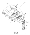
- FIG 1 shows a chassis 1 according to the invention, which comprises a frame 2, a slide 3 that is movable with respect to the frame 2 and a base element 4 supported by the slide 3.
- a child vehicle seat can be detachably connected to the base element 4 in a manner that is known per se.
- the frame 2 comprises a U-shaped frame portion 5, which comprises two legs 6, 7 that extend parallel to each other and a bridge portion 8 that interconnects the legs.
- the legs 6, 7 are provided with connectors 9, 10 on sides remote from the bridge portion 8, which connectors can be detachably connected to securing elements 11, 12 that are present in a vehicle (see figures 3A-6D ).
- a tube 13 Disposed on a side of the bridge portion 8 that faces away from the legs 9, 10 is a tube 13, which extends transversely to the bridge portion 8.
- the frame 2 is furthermore provided with a shaft 14 that extends parallel to the tube 13, which shaft is rotatably supported in the bridge portion 8 and which extends through the slide 3.
- the frame 2 is furthermore provided with a rack 15 that extends parallel to the tube 13, through the slide 3.
- the tube 13 is provided with a supporting leg 16, which is pivotable about a pivot axis that extends parallel to the bridge portion 8.
- the supporting leg 16 is telescopic and is provided with indicating means 17 near a side remote from the tube 13, which indicating means 17 shows up green or red, depending on whether a pressure is or is not being exerted on the underside of the supporting leg 16.
- the indicating means 17 may be provided with a tilting mechanism, for example, which can tilt against spring force, so that a different colour will show up.
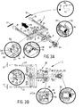
- the chassis 1 will now be explained in more detail with reference to figures 3A-6D .
- FIGS 3A-6D are perspective views and top plan views of the chassis 1 that is shown in figure 1 , in which a cover of the bridge portion 8 as well as part of the tube have been removed, among other parts, so as to provide a better view of the interior of the chassis 1. Relevant details are shown in larger-scale view in a few encircled portions.
- the connectors 9, 10 are not connected to the securing element 11, 12 yet, and the slide 3 is in the first position.
- the shaft 14 is positioned in the slide 3 with one end thereof, being provided with a recess 18 near said end.
- Positioned in said recess 18 is one end of a pin 19, which pin is slidably supported in a bush 20 that is connected to the slide 3.
- the connectors 9, 10 are connected to shafts 21, 22, respectively, which are positioned in the associated legs 6, 7.
- the shafts 21, 22 are connected at their ends remote from the connectors 9, 10 to levers that are pivotable about pivot pins 23, 24.
- the ends of the levers 25, 26 are slidably supported in a box-like element 50 that is located near the centre of the bridge portion 8.
- the box-like element 50 is provided with a bush 27, in which the shaft 14 is slidably supported.
- the bush 27 is provided with a groove 21 that extends obliquely over the circumference of the bush, in which a pin 29 that is connected to the shaft 14 is present.
- the box-shaped element 50 is provided with two recesses 51, 52, in which ends of the levers 25, 26 are positioned. The width of the recesses 51, 52 is greater than that of the levers 25, 26.
- the box-like element 50 is connected to a pin 31 that extends within the tube 13.
- the pin 31 is pressed in the opposite direction of the arrow P1 under the influence of a spring 33.
- the pin 31 is provided with a sleeve 32 on a side remote from the levers 25, 26.
- Disposed within the sleeve 32 is a cap 34, which is movable in the direction indicated by the arrow P1 against the spring force of a spring (not shown).
- the cap 34 is preferably coloured red, whilst the sleeve 32 is preferably coloured green. The red cap 34 indicates that the connectors 9, 10 are not connected to the securing elements 11, 12.
- the chassis 1 is furthermore provided with a ratchet mechanism 35, which comprises a rack 36 that is connected to the bridge portion 8 and a cam 38 that is pivotally connected to the slide 3 via a pivot pin 37, which cam engages with the rack 36 under spring force.
- the rack 36 extends parallel to a strip 36' provided with two slots 40 that extend parallel to each other, at an angle to the rack 36, in which slots 40 pins 41 that are connected to the rack 36 are positioned.
- the strip 36' is connected to the box-shaped element 50 via a spring 39.
- figures 3A-3D show the chassis 1 in the starting position from which the chassis 1 can be connected to the securing elements 11, 12.
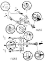
- the slide 3 is locked against movement in the direction of the connectors 9, 10 by the pin 19 and the recess 18 in the shaft 14.
- the red cap 34 indicates that the connectors 9, 10 are disconnected from the securing elements.
- a base element as shown in figure 1 or a child vehicle seat that is known per se are present on the slide 3.
- Movement of the slide 3 in a direction opposite to the direction indicated by the arrow P1 is prevented in a simple manner by the cam 38, however, which will engage the rack 36.
- the user will move the slide 3 and the child vehicle seat that is connected to the slide 3 in the direction indicated by the arrow P1 until the child vehicle seat firmly abuts against the vehicle seat.
- the pin 31 will not be moved in the opposite direction of the arrow P1, so that the red cap will remain visible to the user.
- the user is thus given two indications that the chassis 1 is not correctly connected to the connectors 9, 10.
- the securing elements 11, 12 are staggered relative to each other in figures 4E and 4F . In practice the securing element will be positioned near the connector in the unconnected condition of the connector.
- FIGS 5A and 5B show the situation in which the chassis 1 is connected to the securing elements 11, 12 and in which the slide 3 has moved from the first position to a desired second position, with the child vehicle seat that is connected to the slide 3 firmly abutting against the vehicle seat. Movement of the slide 3 in the opposite direction of the arrow P1 is prevented as a result of the engagement of the cam 38 with the rack 36.
- the strip 36' that is connected to the box-shaped element 50 by means of a spring 39 is moved with respect to the bridge portion 8 when a sufficiently large force is exerted on the sleeve 32 and the cap 34, causing the strip 36' to slide over the pins 41 via the slots 40, moving in a direction indicated by the arrow P11, transversely to the direction indicated by the arrow P1.
- the cam 38 is moved against spring force in the direction indicated by the arrow P7, out of engagement with the rack 36.
- the user can release the sleeve 32 and the cap 34, after which the strip 36' will take up the position that is shown in figures 3A, 3B again.
- the cap 34 too, will return to the position in which it projects from the sleeve 32, so that it will be apparent to the user that the connectors 9, 10 are no longer connected to the securing elements 11, 12.
- the unlocking mechanism formed in part by the sleeve 32 and the cap 34 thus functions to indicate whether the connectors are connected to the securing elements or not, and to disconnect the connectors 9, 10 from the securing elements.
- the unlocking mechanism also makes it possible to move the slide 3 from the second position to the first position again.
Landscapes
- Engineering & Computer Science (AREA)
- Health & Medical Sciences (AREA)
- Child & Adolescent Psychology (AREA)
- General Health & Medical Sciences (AREA)
- Aviation & Aerospace Engineering (AREA)
- Transportation (AREA)
- Mechanical Engineering (AREA)
- Seats For Vehicles (AREA)
- Passenger Equipment (AREA)
- Toys (AREA)
Claims (13)
- Gestell (1), geeignet zum Aufnehmen und Tragen eines Fahrzeugkindersitzes und versehen mit einem wenigstens zwei Verbinder (9, 10) aufweisenden Rahmen (2), wobei die Verbinder (9, 10) beim Gebrauch mit wenigstens zwei im Fahrzeug vorhandenen Befestigungselementen (11, 12) abnehmbar verbunden werden können, wobei das Gestell (1) ferner mit einer Entriegelungsvorrichtung zum Lösen der Verbindung zwischen den Verbindern (9, 10) und den Befestigungselementen (11, 12) sowie mit einem Schlitten (3) zum Tragen des Fahrzeugkindersitzes versehen ist, wobei der Schlitten (3) bezüglich des Rahmens (2) in der Position, in welcher die Verbinder (9, 10) mit den Befestigungselementen (11, 12) verbunden sind, aus einer ersten Lage, in welcher der Schlitten (3) sich in relativ großem Abstand von den Verbindern (9, 10) befindet, in eine zweite Lage, in denen der Schlitten (3) den Verbindern (9, 10) näher ist, und umgekehrt bewegt werden kann, wobei der Schlitten (3) gegen eine Bewegung aus der zweiten Lage in die erste Lage verriegelt ist, wenn die Verbinder (9, 10) mit den Befestigungselementen (11, 12)verbunden sind, dadurch gekennzeichnet, dass alle Verbinder (9, 10) mit einer gemeinsamen Lösevorrichtung verbunden sind, die beim Gebrauch eine Bewegung des Schlittens (3) aus der ersten Lage in die zweite Lage nur dann zulässt, wenn alle Verbinder (9, 10) mit den Befestigungselementen (11, 12) verbunden sind.
- Gestell (1) nach Anspruch 1, dadurch gekennzeichnet, dass alle Verbinder (9, 10) mit der gemeinsamen Lösevorrichtung verbunden sind, welche im Betrieb eine Bewegung des Schlittens (3) aus der zweiten Lage in die erste Lage zulässt.
- Gestell (1) nach Anspruch 1 oder 2, dadurch gekennzeichnet, dass alle Verbindungen zwischen den Verbindern (9, 10) und den Befestigungselementen (11, 12) im Wesentlichen gleichzeitig mittels der Entriegelungsvorrichtung gelöst werden können.
- Gestell (1) nach einem der vorangehenden Ansprüche, dadurch gekennzeichnet, dass jeder Verbinder (9, 10) über einen Hebel mit der Entriegelungsvorrichtung verbunden ist.
- Gestell (1) nach Anspruch 4, dadurch gekennzeichnet, dass die Lösevorrichtung eine Welle (14) umfasst, die sich um die Mittelachse dreht, wobei die Welle (14) in der Nähe des Schlittens (3) mit einer Ausnehmung versehen ist, in welcher in der gelösten Position der Verbinder (9, 10) ein mit dem Schlitten (3) verbundener Stift gelagert ist, während die Welle (14) in der verbundenen Position der Verbinder (9, 10) mittels der Hebel (17) um die Mittelachse gedreht werden kann, wodurch der Stift aus der Ausnehmung heraus bewegt werden und der Schlitten (3) aus der ersten Lage in die zweite Lage bewegt werden kann.
- Gestell (1) nach einem der vorangehenden Ansprüche, dadurch gekennzeichnet, dass das Gestell (1) mit einem Sperrgetriebe mit einer Zahnstange (15) und einer in diese Zahnstange (15) eingreifenden Klinke versehen ist, wobei der Rahmen (2) mit der Zahnstange (15) und der Schlitten (3) mit der Klinke, oder umgekehrt, versehen ist, wobei durch das Sperrgetriebe der Schlitten (3) relativ zum Rahmen (2) aus der ersten Lage in die zweite Lage bewegt werden kann, während die Klinke den Schlitten (3) gegen eine Bewegung aus der zweiten Lage in die erste Lage verriegelt.
- Gestell (1) nach einem der vorangehenden Ansprüche, dadurch gekennzeichnet, dass die Klinke mittels der Entriegelungsvorrichtung (17) aus dem Eingriff mit der Zahnstange (15) bewegt werden kann, wobei in dieser Position der Schlitten aus der zweiten Lage in die erste Lage bewegt werden kann.
- Gestell (1) nach einem der vorangehenden Ansprüche, dadurch gekennzeichnet, dass die Entriegelungsvorrichtung mit mindestens einer Anzeige versehen ist, die anzeigt, ob alle Verbinder (9, 10) von den Befestigungselementen (11, 12) gelöst oder mit diesen verbunden sind.
- Gestell (1) nach einem der vorangehenden Ansprüche, dadurch gekennzeichnet, dass die Entriegelungsvorrichtung in der Nähe einer Seite des Rahmens (2) und von den Verbindern (9, 10) entfernt angebracht ist.
- Gestell (1) nach einem der vorangehenden Ansprüche, dadurch gekennzeichnet, dass der Rahmen (2) auf einer von den Verbindern (9, 10) entfernten Seite mit einer Stütze (16) versehen ist, die mit dem Rahmen (2) schwenkbar verbunden ist.
- Gestell (1) nach Anspruch 10, dadurch gekennzeichnet, dass die Stütze (16) an einem Ende mit mindestens mit einer Anzeige (17) versehen ist, welche Anzeige (17) anzeigt, ob auf ein Ende der Stütze (16) eine vorbestimmte Mindestkraft ausgeübt wird.
- Gestell (1) nach einem der vorangehenden Ansprüche, dadurch gekennzeichnet, dass der Schlitten (3) ein Basiselement (4) aufweist, mit dem ein Fahrzeugkindersitz abnehmbar verbunden werden kann.
- Mit einem Gestell (1) nach einem der vorangehenden Ansprüche versehener Fahrzeugkindersitz.
Priority Applications (1)
| Application Number | Priority Date | Filing Date | Title |
|---|---|---|---|
| PL06075833T PL1714826T3 (pl) | 2005-04-18 | 2006-04-06 | Podstawa oraz dziecięcy fotelik do pojazdów wyposażony w taką podstawę |
Applications Claiming Priority (1)
| Application Number | Priority Date | Filing Date | Title |
|---|---|---|---|
| NL1028788A NL1028788C2 (nl) | 2005-04-18 | 2005-04-18 | Onderstel alsmede kindervoertuigstoel voorzien van een dergelijk onderstel. |
Publications (2)
| Publication Number | Publication Date |
|---|---|
| EP1714826A1 EP1714826A1 (de) | 2006-10-25 |
| EP1714826B1 true EP1714826B1 (de) | 2009-06-10 |
Family
ID=35735000
Family Applications (1)
| Application Number | Title | Priority Date | Filing Date |
|---|---|---|---|
| EP06075833A Not-in-force EP1714826B1 (de) | 2005-04-18 | 2006-04-06 | Gestell und Fahrzeugsitz mit einem solchen Gestell für Kinder |
Country Status (9)
| Country | Link |
|---|---|
| US (1) | US7328946B2 (de) |
| EP (1) | EP1714826B1 (de) |
| CN (1) | CN1876434B (de) |
| AT (1) | ATE433391T1 (de) |
| DE (1) | DE602006007189D1 (de) |
| ES (1) | ES2326993T3 (de) |
| NL (1) | NL1028788C2 (de) |
| PL (1) | PL1714826T3 (de) |
| PT (1) | PT1714826E (de) |
Cited By (3)
| Publication number | Priority date | Publication date | Assignee | Title |
|---|---|---|---|---|
| US8998317B2 (en) | 2012-05-15 | 2015-04-07 | Wonderland Nurserygoods Company Limited | Support base for a child safety seat |
| EP3347234B1 (de) | 2015-09-09 | 2020-11-04 | CYBEX GmbH | Kindersitz zur anbringung auf einem kraftfahrzeugsitz |
| DE102013107424B4 (de) | 2013-07-12 | 2023-05-17 | RECARO Kids S.r.l. | Basis zur Montage eines Sicherheitskindersitzes auf einem Fahrzeugsitz |
Families Citing this family (43)
| Publication number | Priority date | Publication date | Assignee | Title |
|---|---|---|---|---|
| FR2889826B1 (fr) * | 2005-08-17 | 2008-10-17 | Equipbaby Uk Ltd | Siege de securite destine a installer un bebe ou un tres jeune enfant sur un siege de vehicule. |
| ES1063434Y (es) * | 2006-07-14 | 2007-01-16 | Jane Sa | Base para el acoplamiento de asientos infantiles en automoviles |
| ES2315136B1 (es) * | 2006-11-16 | 2010-01-12 | Play, S.A. | Dispositivo de accionamiento del sistema de anclaje de un asiento infantil para automoviles. |
| EP1970247A1 (de) * | 2007-03-15 | 2008-09-17 | Team-Tex | Vorrichtung zum Anbringen eines Kindersitzes in einem Auto und Kindersitz |
| US20080290709A1 (en) * | 2007-05-25 | 2008-11-27 | Joseph Wayne Kraft | Rigid Mounting Device for a Child Safety Seat |
| DE602008003888D1 (de) * | 2007-12-21 | 2011-01-20 | Jane Sa | Kindersitz für Kraftfahrzeuge |
| JP5247161B2 (ja) * | 2008-01-18 | 2013-07-24 | アップリカ・チルドレンズプロダクツ株式会社 | 自動車用チャイルドシート |
| DE202008005361U1 (de) * | 2008-04-17 | 2008-07-03 | Recaro Gmbh & Co. Kg | Vorrichtung zur Befestigung eines Auto-Kindersitzes an einem Verankerungssteg oder -bügel der Karosserie eines Fahrzeugs |
| US8419129B2 (en) * | 2008-07-02 | 2013-04-16 | Combi Corporation | Child car seat |
| US20100013282A1 (en) * | 2008-07-17 | 2010-01-21 | Balensiefer Eugene R | Non-handed mini-connector |
| US8141950B2 (en) * | 2008-08-07 | 2012-03-27 | Immi | Single retractor lower anchor connection system |
| WO2010025571A1 (en) * | 2008-09-05 | 2010-03-11 | Magna Marque International Inc. | Adjuster and hinge for child booster seat |
| NO329442B1 (no) * | 2008-09-08 | 2010-10-18 | Hts Hans Torgersen & Sonn As | Anordning ved et bilbarnesete |
| NL1036452C2 (en) * | 2009-01-23 | 2010-07-26 | Maxi Miliaan Bv | A child vehicle seat as well as a chassis suitable for such a child vehicle seat. |
| DE102009003629B4 (de) | 2009-03-17 | 2013-03-21 | Curt Würstl Vermögensverwaltungs-Gmbh & Co. Kg | Sitzverankerungselement für Kindersicherheitssitze oder Babyträger |
| DE202009001975U1 (de) | 2009-03-17 | 2009-05-28 | Curt Würstl Vermögensverwaltungs-Gmbh & Co. Kg | Sitzverankerungselement für Kindersicherheitssitze oder Babyträger |
| CN101780335B (zh) * | 2009-09-25 | 2012-10-03 | 东莞市新雷神仿真控制有限公司 | 一种游戏体验装置 |
| CN102985286B (zh) * | 2010-03-24 | 2015-12-16 | 谛欧诺有限责任公司 | 倾斜骑倒式儿童座椅 |
| JP5596485B2 (ja) * | 2010-10-06 | 2014-09-24 | タカタ株式会社 | チャイルドシート |
| DE202010008803U1 (de) | 2010-10-13 | 2011-01-13 | Curt Würstl Vermögensverwaltungs-Gmbh & Co. Kg | Sitzverankerungselement für Kindersicherheitssitze oder Babyträger |
| CN102729854B (zh) * | 2011-04-11 | 2015-06-24 | 明门香港股份有限公司 | 支撑装置及具有该装置的儿童安全座椅 |
| CN202071722U (zh) * | 2011-04-26 | 2011-12-14 | 中山市隆成日用制品有限公司 | 安全座椅基座的支撑架警示装置 |
| NO336044B1 (no) * | 2011-06-14 | 2015-04-27 | HTS Hans Torgersen & Sønn AS | En base for et barnesete |
| EP2546096B1 (de) * | 2011-07-14 | 2013-09-11 | Volvo Car Corporation | Kindersitz |
| EP2551150B1 (de) * | 2011-07-29 | 2016-12-14 | Wonderland Nurserygoods Company Limited | Kindersitzanordnungen mit Verankerungssystemen |
| CN103042953A (zh) * | 2011-10-11 | 2013-04-17 | 宝钜儿童用品香港股份有限公司 | 支撑脚安全指示装置 |
| DE202012101091U1 (de) | 2012-03-27 | 2012-05-31 | Curt Würstl Vermögensverwaltungs-Gmbh & Co. Kg | Befestigungsvorrichtung |
| CN103770671B (zh) * | 2012-10-17 | 2016-06-29 | 明门香港股份有限公司 | 婴儿安全座椅的底座 |
| US9242584B2 (en) * | 2013-01-18 | 2016-01-26 | Wonderland Nurserygoods Company Limited | Child safety seat assembly |
| CN203267824U (zh) * | 2013-05-02 | 2013-11-06 | 中山市隆成日用制品有限公司 | 安全座椅基座的支撑架色显机构 |
| US9227537B2 (en) * | 2013-09-27 | 2016-01-05 | Wonderland Nurserygoods Company Limited | Seat buffering device and vehicle safety seat having the same |
| DE202015100327U1 (de) * | 2015-01-23 | 2016-04-26 | Wolfgang Nickel | Aufnahmevorrichtung |
| EP3604029B1 (de) * | 2015-04-28 | 2021-04-14 | Volvo Car Corporation | Stützanordnung mit kindersitz |
| CN107826001B (zh) * | 2016-09-16 | 2020-05-22 | 明门瑞士股份有限公司 | 支撑脚以及其儿童安全座椅总成 |
| CN108058624B (zh) * | 2016-11-08 | 2021-02-09 | 明门瑞士股份有限公司 | 儿童安全座椅 |
| US11006612B2 (en) * | 2017-07-25 | 2021-05-18 | Scott Andrew Ryan | Adjustable vehicle pet platform assembly and method of use |
| CN208248019U (zh) * | 2018-02-01 | 2018-12-18 | 麦克英孚(宁波)婴童用品有限公司 | 一种带微动开关的支撑腿结构 |
| US11097639B2 (en) | 2018-05-24 | 2021-08-24 | Wonderland Switzerland Ag | Support base for a child safety seat |
| WO2020023609A1 (en) | 2018-07-27 | 2020-01-30 | Safest Seats Llc | Support platform with load leg for child car seat |
| CN109398180B (zh) * | 2018-12-18 | 2023-09-29 | 麦克英孚(宁波)婴童用品有限公司 | 一种isofix释锁机构及使用其的儿童安全座椅 |
| CN113002383B (zh) * | 2019-12-18 | 2023-06-30 | 宝钜瑞士股份有限公司 | 儿童安全座椅 |
| US11425886B2 (en) * | 2020-10-23 | 2022-08-30 | Ford Global Technologies, Llc | Pet restraint system |
| CN115339362A (zh) * | 2021-05-14 | 2022-11-15 | 明门瑞士股份有限公司 | 防跳挡装置和具有防跳挡装置的座椅搁脚装置及儿童安全座椅 |
Family Cites Families (7)
| Publication number | Priority date | Publication date | Assignee | Title |
|---|---|---|---|---|
| GB9808785D0 (en) | 1998-04-25 | 1998-06-24 | Britax Excelsior | Child safety seat |
| DE69919942T2 (de) | 1998-07-06 | 2005-11-17 | Bröderna Holmbergs Fabriks AB | Befestigungsvorrichtung für einen Sicherheits-Kindersitz |
| JP3656512B2 (ja) * | 1999-05-10 | 2005-06-08 | タカタ株式会社 | チャイルドシート |
| DE19946579A1 (de) * | 1999-09-29 | 2001-04-05 | Opel Adam Ag | Befestigungsvorrichtung für einen Kindersitz in einem Kraftfahrzeug |
| JP2001206117A (ja) * | 2000-01-27 | 2001-07-31 | Honda Motor Co Ltd | 幼児用シートのアタッチメント |
| ES2196999A1 (es) * | 2002-03-14 | 2003-12-16 | Play Sa | Silla infantil para automoviles. |
| NL1023422C2 (nl) * | 2003-05-14 | 2004-11-16 | Maxi Miliaan Bv | Kindervoertuigstoel. |
-
2005
- 2005-04-18 NL NL1028788A patent/NL1028788C2/nl not_active IP Right Cessation
-
2006
- 2006-04-06 EP EP06075833A patent/EP1714826B1/de not_active Not-in-force
- 2006-04-06 AT AT06075833T patent/ATE433391T1/de not_active IP Right Cessation
- 2006-04-06 ES ES06075833T patent/ES2326993T3/es active Active
- 2006-04-06 PT PT06075833T patent/PT1714826E/pt unknown
- 2006-04-06 DE DE602006007189T patent/DE602006007189D1/de active Active
- 2006-04-06 PL PL06075833T patent/PL1714826T3/pl unknown
- 2006-04-18 US US11/407,384 patent/US7328946B2/en not_active Expired - Fee Related
- 2006-04-18 CN CN2006101054790A patent/CN1876434B/zh not_active Expired - Fee Related
Cited By (3)
| Publication number | Priority date | Publication date | Assignee | Title |
|---|---|---|---|---|
| US8998317B2 (en) | 2012-05-15 | 2015-04-07 | Wonderland Nurserygoods Company Limited | Support base for a child safety seat |
| DE102013107424B4 (de) | 2013-07-12 | 2023-05-17 | RECARO Kids S.r.l. | Basis zur Montage eines Sicherheitskindersitzes auf einem Fahrzeugsitz |
| EP3347234B1 (de) | 2015-09-09 | 2020-11-04 | CYBEX GmbH | Kindersitz zur anbringung auf einem kraftfahrzeugsitz |
Also Published As
| Publication number | Publication date |
|---|---|
| NL1028788C2 (nl) | 2006-10-20 |
| US7328946B2 (en) | 2008-02-12 |
| EP1714826A1 (de) | 2006-10-25 |
| DE602006007189D1 (de) | 2009-07-23 |
| CN1876434A (zh) | 2006-12-13 |
| CN1876434B (zh) | 2010-05-12 |
| PT1714826E (pt) | 2009-07-27 |
| ATE433391T1 (de) | 2009-06-15 |
| ES2326993T3 (es) | 2009-10-22 |
| PL1714826T3 (pl) | 2009-10-30 |
| US20070069562A1 (en) | 2007-03-29 |
Similar Documents
| Publication | Publication Date | Title |
|---|---|---|
| EP1714826B1 (de) | Gestell und Fahrzeugsitz mit einem solchen Gestell für Kinder | |
| US8033555B2 (en) | Assembly comprising a chassis and a child seat being detachably connectable to the chassis, such a chassis as well as such a child seat | |
| EP0602696B1 (de) | Fahrzeugsitz | |
| CN107826006B (zh) | 用来将儿童拘束系统组装在汽车座椅上的安全带组装装置 | |
| US8070228B2 (en) | Child vehicle seat | |
| US10308146B1 (en) | Track release mechanism for a seating assembly | |
| EP1731355B1 (de) | Ein Rahmen und ein Aufbau mit solch einem Rahmen | |
| US5765894A (en) | Seat device for a vehicle | |
| US8328208B2 (en) | Stroller connectable with a car seat | |
| CA1055556A (en) | Folding table with locking hinge | |
| JP3011268B1 (ja) | ベルト付きカート | |
| KR101694910B1 (ko) | 헤드레스트 슬라이딩 장치 | |
| JP5087546B2 (ja) | 連結システムを備える自動二輪車のケースアセンブリ | |
| CN102381223B (zh) | 用于车辆的后座桌组件 | |
| US8511752B2 (en) | No-tools chair assembly | |
| US10647236B2 (en) | Dual cam latch | |
| EP1491391B1 (de) | Fahrzeugsitz, der zu einem bett umgewandelt werden kann | |
| EP2832625B1 (de) | Rahmen für Kinderwagen sowie faltbares und abnehmbares Sitzgestell | |
| US6561583B2 (en) | Mechanism for joining a removable seat with tilting seat pan to the floor of an automobile vehicle | |
| AU734034B2 (en) | A full floating device of a rear seat cushion for an automobile | |
| US7604295B2 (en) | Child vehicle seat | |
| EP1930205B1 (de) | Kindersitz für Fahrzeuge | |
| CA2788465C (en) | Coupler for a vehicle and a vehicle comprising same | |
| EP1369293A1 (de) | Fahrzeugkindersitz mit einem Untergestell und Sitz verbunden mit dem Untergestell, sowie ein solches Untergestell | |
| EP1369295A1 (de) | Träger zum Befestigen eines Kindersitzes an einem Fahrzeugsitz, eine solche Einrichtung und ein Fahrzeugkindersitz |
Legal Events
| Date | Code | Title | Description |
|---|---|---|---|
| PUAI | Public reference made under article 153(3) epc to a published international application that has entered the european phase |
Free format text: ORIGINAL CODE: 0009012 |
|
| AK | Designated contracting states |
Kind code of ref document: A1 Designated state(s): AT BE BG CH CY CZ DE DK EE ES FI FR GB GR HU IE IS IT LI LT LU LV MC NL PL PT RO SE SI SK TR |
|
| AX | Request for extension of the european patent |
Extension state: AL BA HR MK YU |
|
| 17P | Request for examination filed |
Effective date: 20070124 |
|
| AKX | Designation fees paid |
Designated state(s): AT BE BG CH CY CZ DE DK EE ES FI FR GB GR HU IE IS IT LI LT LU LV MC NL PL PT RO SE SI SK TR |
|
| 17Q | First examination report despatched |
Effective date: 20071121 |
|
| GRAP | Despatch of communication of intention to grant a patent |
Free format text: ORIGINAL CODE: EPIDOSNIGR1 |
|
| GRAS | Grant fee paid |
Free format text: ORIGINAL CODE: EPIDOSNIGR3 |
|
| GRAA | (expected) grant |
Free format text: ORIGINAL CODE: 0009210 |
|
| AK | Designated contracting states |
Kind code of ref document: B1 Designated state(s): AT BE BG CH CY CZ DE DK EE ES FI FR GB GR HU IE IS IT LI LT LU LV MC NL PL PT RO SE SI SK TR |
|
| REG | Reference to a national code |
Ref country code: GB Ref legal event code: FG4D |
|
| REG | Reference to a national code |
Ref country code: CH Ref legal event code: EP |
|
| REG | Reference to a national code |
Ref country code: IE Ref legal event code: FG4D |
|
| REF | Corresponds to: |
Ref document number: 602006007189 Country of ref document: DE Date of ref document: 20090723 Kind code of ref document: P |
|
| REG | Reference to a national code |
Ref country code: PT Ref legal event code: SC4A Free format text: AVAILABILITY OF NATIONAL TRANSLATION Effective date: 20090720 |
|
| REG | Reference to a national code |
Ref country code: SE Ref legal event code: TRGR |
|
| REG | Reference to a national code |
Ref country code: ES Ref legal event code: FG2A Ref document number: 2326993 Country of ref document: ES Kind code of ref document: T3 |
|
| PG25 | Lapsed in a contracting state [announced via postgrant information from national office to epo] |
Ref country code: AT Free format text: LAPSE BECAUSE OF FAILURE TO SUBMIT A TRANSLATION OF THE DESCRIPTION OR TO PAY THE FEE WITHIN THE PRESCRIBED TIME-LIMIT Effective date: 20090610 Ref country code: FI Free format text: LAPSE BECAUSE OF FAILURE TO SUBMIT A TRANSLATION OF THE DESCRIPTION OR TO PAY THE FEE WITHIN THE PRESCRIBED TIME-LIMIT Effective date: 20090610 Ref country code: LT Free format text: LAPSE BECAUSE OF FAILURE TO SUBMIT A TRANSLATION OF THE DESCRIPTION OR TO PAY THE FEE WITHIN THE PRESCRIBED TIME-LIMIT Effective date: 20090610 |
|
| REG | Reference to a national code |
Ref country code: PL Ref legal event code: T3 |
|
| PG25 | Lapsed in a contracting state [announced via postgrant information from national office to epo] |
Ref country code: SI Free format text: LAPSE BECAUSE OF FAILURE TO SUBMIT A TRANSLATION OF THE DESCRIPTION OR TO PAY THE FEE WITHIN THE PRESCRIBED TIME-LIMIT Effective date: 20090610 Ref country code: LV Free format text: LAPSE BECAUSE OF FAILURE TO SUBMIT A TRANSLATION OF THE DESCRIPTION OR TO PAY THE FEE WITHIN THE PRESCRIBED TIME-LIMIT Effective date: 20090610 |
|
| PG25 | Lapsed in a contracting state [announced via postgrant information from national office to epo] |
Ref country code: RO Free format text: LAPSE BECAUSE OF FAILURE TO SUBMIT A TRANSLATION OF THE DESCRIPTION OR TO PAY THE FEE WITHIN THE PRESCRIBED TIME-LIMIT Effective date: 20090610 Ref country code: IS Free format text: LAPSE BECAUSE OF FAILURE TO SUBMIT A TRANSLATION OF THE DESCRIPTION OR TO PAY THE FEE WITHIN THE PRESCRIBED TIME-LIMIT Effective date: 20091010 Ref country code: CZ Free format text: LAPSE BECAUSE OF FAILURE TO SUBMIT A TRANSLATION OF THE DESCRIPTION OR TO PAY THE FEE WITHIN THE PRESCRIBED TIME-LIMIT Effective date: 20090610 Ref country code: EE Free format text: LAPSE BECAUSE OF FAILURE TO SUBMIT A TRANSLATION OF THE DESCRIPTION OR TO PAY THE FEE WITHIN THE PRESCRIBED TIME-LIMIT Effective date: 20090610 |
|
| PG25 | Lapsed in a contracting state [announced via postgrant information from national office to epo] |
Ref country code: SK Free format text: LAPSE BECAUSE OF FAILURE TO SUBMIT A TRANSLATION OF THE DESCRIPTION OR TO PAY THE FEE WITHIN THE PRESCRIBED TIME-LIMIT Effective date: 20090610 Ref country code: BE Free format text: LAPSE BECAUSE OF FAILURE TO SUBMIT A TRANSLATION OF THE DESCRIPTION OR TO PAY THE FEE WITHIN THE PRESCRIBED TIME-LIMIT Effective date: 20090610 |
|
| PG25 | Lapsed in a contracting state [announced via postgrant information from national office to epo] |
Ref country code: BG Free format text: LAPSE BECAUSE OF FAILURE TO SUBMIT A TRANSLATION OF THE DESCRIPTION OR TO PAY THE FEE WITHIN THE PRESCRIBED TIME-LIMIT Effective date: 20090910 |
|
| PLBE | No opposition filed within time limit |
Free format text: ORIGINAL CODE: 0009261 |
|
| STAA | Information on the status of an ep patent application or granted ep patent |
Free format text: STATUS: NO OPPOSITION FILED WITHIN TIME LIMIT |
|
| PG25 | Lapsed in a contracting state [announced via postgrant information from national office to epo] |
Ref country code: DK Free format text: LAPSE BECAUSE OF FAILURE TO SUBMIT A TRANSLATION OF THE DESCRIPTION OR TO PAY THE FEE WITHIN THE PRESCRIBED TIME-LIMIT Effective date: 20090610 |
|
| PGFP | Annual fee paid to national office [announced via postgrant information from national office to epo] |
Ref country code: PT Payment date: 20100325 Year of fee payment: 5 |
|
| 26N | No opposition filed |
Effective date: 20100311 |
|
| PG25 | Lapsed in a contracting state [announced via postgrant information from national office to epo] |
Ref country code: GR Free format text: LAPSE BECAUSE OF FAILURE TO SUBMIT A TRANSLATION OF THE DESCRIPTION OR TO PAY THE FEE WITHIN THE PRESCRIBED TIME-LIMIT Effective date: 20090911 |
|
| PG25 | Lapsed in a contracting state [announced via postgrant information from national office to epo] |
Ref country code: MC Free format text: LAPSE BECAUSE OF NON-PAYMENT OF DUE FEES Effective date: 20100430 |
|
| REG | Reference to a national code |
Ref country code: CH Ref legal event code: PL |
|
| PG25 | Lapsed in a contracting state [announced via postgrant information from national office to epo] |
Ref country code: IE Free format text: LAPSE BECAUSE OF NON-PAYMENT OF DUE FEES Effective date: 20100406 |
|
| PG25 | Lapsed in a contracting state [announced via postgrant information from national office to epo] |
Ref country code: LI Free format text: LAPSE BECAUSE OF NON-PAYMENT OF DUE FEES Effective date: 20100430 Ref country code: CH Free format text: LAPSE BECAUSE OF NON-PAYMENT OF DUE FEES Effective date: 20100430 |
|
| REG | Reference to a national code |
Ref country code: PT Ref legal event code: MM4A Free format text: LAPSE DUE TO NON-PAYMENT OF FEES Effective date: 20111006 |
|
| PG25 | Lapsed in a contracting state [announced via postgrant information from national office to epo] |
Ref country code: PT Free format text: LAPSE BECAUSE OF NON-PAYMENT OF DUE FEES Effective date: 20111006 |
|
| PG25 | Lapsed in a contracting state [announced via postgrant information from national office to epo] |
Ref country code: CY Free format text: LAPSE BECAUSE OF FAILURE TO SUBMIT A TRANSLATION OF THE DESCRIPTION OR TO PAY THE FEE WITHIN THE PRESCRIBED TIME-LIMIT Effective date: 20090610 |
|
| PG25 | Lapsed in a contracting state [announced via postgrant information from national office to epo] |
Ref country code: LU Free format text: LAPSE BECAUSE OF NON-PAYMENT OF DUE FEES Effective date: 20100406 Ref country code: HU Free format text: LAPSE BECAUSE OF FAILURE TO SUBMIT A TRANSLATION OF THE DESCRIPTION OR TO PAY THE FEE WITHIN THE PRESCRIBED TIME-LIMIT Effective date: 20091211 |
|
| PG25 | Lapsed in a contracting state [announced via postgrant information from national office to epo] |
Ref country code: TR Free format text: LAPSE BECAUSE OF FAILURE TO SUBMIT A TRANSLATION OF THE DESCRIPTION OR TO PAY THE FEE WITHIN THE PRESCRIBED TIME-LIMIT Effective date: 20090610 |
|
| PGFP | Annual fee paid to national office [announced via postgrant information from national office to epo] |
Ref country code: SE Payment date: 20130418 Year of fee payment: 8 |
|
| PGFP | Annual fee paid to national office [announced via postgrant information from national office to epo] |
Ref country code: PL Payment date: 20130405 Year of fee payment: 8 |
|
| REG | Reference to a national code |
Ref country code: SE Ref legal event code: EUG |
|
| PG25 | Lapsed in a contracting state [announced via postgrant information from national office to epo] |
Ref country code: SE Free format text: LAPSE BECAUSE OF NON-PAYMENT OF DUE FEES Effective date: 20140407 |
|
| REG | Reference to a national code |
Ref country code: FR Ref legal event code: PLFP Year of fee payment: 11 |
|
| PG25 | Lapsed in a contracting state [announced via postgrant information from national office to epo] |
Ref country code: PL Free format text: LAPSE BECAUSE OF NON-PAYMENT OF DUE FEES Effective date: 20140406 |
|
| REG | Reference to a national code |
Ref country code: FR Ref legal event code: PLFP Year of fee payment: 12 |
|
| PGFP | Annual fee paid to national office [announced via postgrant information from national office to epo] |
Ref country code: NL Payment date: 20170321 Year of fee payment: 12 |
|
| PGFP | Annual fee paid to national office [announced via postgrant information from national office to epo] |
Ref country code: FR Payment date: 20170419 Year of fee payment: 12 Ref country code: GB Payment date: 20170419 Year of fee payment: 12 Ref country code: DE Payment date: 20170419 Year of fee payment: 12 |
|
| PGFP | Annual fee paid to national office [announced via postgrant information from national office to epo] |
Ref country code: ES Payment date: 20170510 Year of fee payment: 12 Ref country code: IT Payment date: 20170424 Year of fee payment: 12 |
|
| REG | Reference to a national code |
Ref country code: DE Ref legal event code: R119 Ref document number: 602006007189 Country of ref document: DE |
|
| REG | Reference to a national code |
Ref country code: NL Ref legal event code: MM Effective date: 20180501 |
|
| GBPC | Gb: european patent ceased through non-payment of renewal fee |
Effective date: 20180406 |
|
| PG25 | Lapsed in a contracting state [announced via postgrant information from national office to epo] |
Ref country code: NL Free format text: LAPSE BECAUSE OF NON-PAYMENT OF DUE FEES Effective date: 20180501 Ref country code: DE Free format text: LAPSE BECAUSE OF NON-PAYMENT OF DUE FEES Effective date: 20181101 |
|
| PG25 | Lapsed in a contracting state [announced via postgrant information from national office to epo] |
Ref country code: GB Free format text: LAPSE BECAUSE OF NON-PAYMENT OF DUE FEES Effective date: 20180406 |
|
| PG25 | Lapsed in a contracting state [announced via postgrant information from national office to epo] |
Ref country code: IT Free format text: LAPSE BECAUSE OF NON-PAYMENT OF DUE FEES Effective date: 20180406 Ref country code: FR Free format text: LAPSE BECAUSE OF NON-PAYMENT OF DUE FEES Effective date: 20180430 |
|
| REG | Reference to a national code |
Ref country code: ES Ref legal event code: FD2A Effective date: 20190911 |
|
| PG25 | Lapsed in a contracting state [announced via postgrant information from national office to epo] |
Ref country code: ES Free format text: LAPSE BECAUSE OF NON-PAYMENT OF DUE FEES Effective date: 20180407 |