EP1714692B1 - Dialysefilter - Google Patents
Dialysefilter Download PDFInfo
- Publication number
- EP1714692B1 EP1714692B1 EP05008649A EP05008649A EP1714692B1 EP 1714692 B1 EP1714692 B1 EP 1714692B1 EP 05008649 A EP05008649 A EP 05008649A EP 05008649 A EP05008649 A EP 05008649A EP 1714692 B1 EP1714692 B1 EP 1714692B1
- Authority
- EP
- European Patent Office
- Prior art keywords
- fibers
- packing density
- hollow fibers
- housing
- fiber bundle
- Prior art date
- Legal status (The legal status is an assumption and is not a legal conclusion. Google has not performed a legal analysis and makes no representation as to the accuracy of the status listed.)
- Expired - Lifetime
Links
Images

Classifications
-
- B—PERFORMING OPERATIONS; TRANSPORTING
- B01—PHYSICAL OR CHEMICAL PROCESSES OR APPARATUS IN GENERAL
- B01D—SEPARATION
- B01D63/00—Apparatus in general for separation processes using semi-permeable membranes
- B01D63/02—Hollow fibre modules
- B01D63/027—Twinned or braided type modules
-
- B—PERFORMING OPERATIONS; TRANSPORTING
- B01—PHYSICAL OR CHEMICAL PROCESSES OR APPARATUS IN GENERAL
- B01D—SEPARATION
- B01D61/00—Processes of separation using semi-permeable membranes, e.g. dialysis, osmosis or ultrafiltration; Apparatus, accessories or auxiliary operations specially adapted therefor
- B01D61/24—Dialysis ; Membrane extraction
- B01D61/243—Dialysis
-
- B—PERFORMING OPERATIONS; TRANSPORTING
- B01—PHYSICAL OR CHEMICAL PROCESSES OR APPARATUS IN GENERAL
- B01D—SEPARATION
- B01D63/00—Apparatus in general for separation processes using semi-permeable membranes
- B01D63/02—Hollow fibre modules
- B01D63/021—Manufacturing thereof
- B01D63/022—Encapsulating hollow fibres
-
- B—PERFORMING OPERATIONS; TRANSPORTING
- B01—PHYSICAL OR CHEMICAL PROCESSES OR APPARATUS IN GENERAL
- B01D—SEPARATION
- B01D63/00—Apparatus in general for separation processes using semi-permeable membranes
- B01D63/02—Hollow fibre modules
- B01D63/021—Manufacturing thereof
- B01D63/0233—Manufacturing thereof forming the bundle
-
- B—PERFORMING OPERATIONS; TRANSPORTING
- B01—PHYSICAL OR CHEMICAL PROCESSES OR APPARATUS IN GENERAL
- B01D—SEPARATION
- B01D63/00—Apparatus in general for separation processes using semi-permeable membranes
- B01D63/02—Hollow fibre modules
- B01D63/025—Bobbin units
-
- B—PERFORMING OPERATIONS; TRANSPORTING
- B01—PHYSICAL OR CHEMICAL PROCESSES OR APPARATUS IN GENERAL
- B01D—SEPARATION
- B01D65/00—Accessories or auxiliary operations, in general, for separation processes or apparatus using semi-permeable membranes
- B01D65/02—Membrane cleaning or sterilisation ; Membrane regeneration
-
- B—PERFORMING OPERATIONS; TRANSPORTING
- B01—PHYSICAL OR CHEMICAL PROCESSES OR APPARATUS IN GENERAL
- B01D—SEPARATION
- B01D69/00—Semi-permeable membranes for separation processes or apparatus characterised by their form, structure or properties; Manufacturing processes specially adapted therefor
- B01D69/08—Hollow fibre membranes
- B01D69/084—Undulated fibres
-
- A—HUMAN NECESSITIES
- A61—MEDICAL OR VETERINARY SCIENCE; HYGIENE
- A61M—DEVICES FOR INTRODUCING MEDIA INTO, OR ONTO, THE BODY; DEVICES FOR TRANSDUCING BODY MEDIA OR FOR TAKING MEDIA FROM THE BODY; DEVICES FOR PRODUCING OR ENDING SLEEP OR STUPOR
- A61M1/00—Suction or pumping devices for medical purposes; Devices for carrying-off, for treatment of, or for carrying-over, body-liquids; Drainage systems
- A61M1/14—Dialysis systems; Artificial kidneys; Blood oxygenators ; Reciprocating systems for treatment of body fluids, e.g. single needle systems for hemofiltration or pheresis
- A61M1/16—Dialysis systems; Artificial kidneys; Blood oxygenators ; Reciprocating systems for treatment of body fluids, e.g. single needle systems for hemofiltration or pheresis with membranes
-
- B—PERFORMING OPERATIONS; TRANSPORTING
- B01—PHYSICAL OR CHEMICAL PROCESSES OR APPARATUS IN GENERAL
- B01D—SEPARATION
- B01D2313/00—Details relating to membrane modules or apparatus
- B01D2313/08—Flow guidance means within the module or the apparatus
-
- B—PERFORMING OPERATIONS; TRANSPORTING
- B01—PHYSICAL OR CHEMICAL PROCESSES OR APPARATUS IN GENERAL
- B01D—SEPARATION
- B01D2313/00—Details relating to membrane modules or apparatus
- B01D2313/10—Specific supply elements
-
- B—PERFORMING OPERATIONS; TRANSPORTING
- B01—PHYSICAL OR CHEMICAL PROCESSES OR APPARATUS IN GENERAL
- B01D—SEPARATION
- B01D2313/00—Details relating to membrane modules or apparatus
- B01D2313/20—Specific housing
- B01D2313/203—Open housings
-
- B—PERFORMING OPERATIONS; TRANSPORTING
- B01—PHYSICAL OR CHEMICAL PROCESSES OR APPARATUS IN GENERAL
- B01D—SEPARATION
- B01D2313/00—Details relating to membrane modules or apparatus
- B01D2313/20—Specific housing
- B01D2313/205—Specific housing characterised by the shape
-
- B—PERFORMING OPERATIONS; TRANSPORTING
- B01—PHYSICAL OR CHEMICAL PROCESSES OR APPARATUS IN GENERAL
- B01D—SEPARATION
- B01D2321/00—Details relating to membrane cleaning, regeneration, sterilization or to the prevention of fouling
- B01D2321/20—By influencing the flow
- B01D2321/2008—By influencing the flow statically
- B01D2321/2025—Tangential inlet
Definitions
- the invention relates to a filter device according to the preamble of claim 1 and in particular a dialysis filter.
- a dialysis filter of this kind is off US-A-5,489,413 known, in which the hollow fiber bundle is arranged annularly in a housing around a central cavity.
- EP-A-0 798 034 describes a hollow fiber filter device in which the hollow fibers are arranged around a central, elongated mandrel having perforations for the passage of the filter medium.
- the hollow fibers are helically wound in a housing and held at the ends in a potting compound.
- the object of the invention is to provide a filter device of the type described in such a way that the filter performance is improved.
- an improvement in the filter performance is achieved in that the packing density of the hollow fiber bundle varies over the length of the bundle and the hollow fiber bundle is expanded, in particular in the inlet and / or outflow of the dialysate, while the packing density in the central region of the hollow fiber bundle is higher.
- the unhindered radial flow of the dialysate in the widened region of the bundle is achieved so that a uniform flow distribution over the entire bundle cross-section results.
- Fig. 1 shows in a longitudinal section a dialyzer with a generally tubular housing 1, which is closed at the end faces by caps 5 and 5 '.
- a bundle of semi-permeable hollow fibers 2 is positioned by two disc-shaped blocks 3 and 3 'of a potting compound, whose circumference rests on the inner circumference of the tubular housing 1 and in which the ends of the individual hollow fibers 2 of the bundle are embedded fluid-tight.
- the respective outer side of the potting compound 3 or 3 ' forms a flat sectional surface 4 or 4' of the hollow fibers transversely to the longitudinal axis of the housing with an opening to the interior of the hollow fibers.
- the sectional plane 4 is located substantially at the level of the edge of the housing 1, wherein the caps 5 extend over the end portion of the housing 1 and are sealed from the housing.
- the cutting plane 4 can also be arranged offset to the edge of the housing.
- the caps 5 and 5 'on the housing 1 are each provided centrally with an inlet conduit 6 and an outlet conduit 6' which extends substantially along the longitudinal axis of the tubular housing 1.
- a dialyzer blood is supplied through the line 6 and discharged via the line 6 '.
- Dialysate is fed in countercurrent through a radially opening into the cap 5 line 7 'and discharged through a line 7.
- the flow direction is indicated by arrows in Fig. 1 played.
- Designated at 8 and 8 ' is a sealing ring between cap 5 and cutting surface 4 which separates two fluid chambers in the dialyzer, a first fluid chamber containing inlet conduit 6 and outlet conduit 6' with the central region in caps 5 and 5 'and Inner of the hollow fibers 2, and a second fluid chamber comprising the lines 7 and 7 'for the dialysate with the flow area outside the sealing ring 8 in the caps and the interior of the housing 1 between the individual hollow fibers 2.
- the substantially axially extending channels 9 ' which in Fig. 2 are shown with a round cross-section, but can also have an elongated rectangular cross-section, preferably have in the inlet region a tapered in the flow direction shape to support the flow distribution in the inlet region.
- the channels 9 are formed in the same way for manufacturing reasons. In this area they can also have a continuous cross-sectional shape.
- the channels 9 'provided on the circumference of the potting compound 3' may be designed differently in terms of their spacing and / or cross section in order to influence the flow profile, in particular in the inlet region.
- Fig. 2 shows by an arrow the inflowing through the inlet line 7 'in the radial direction dialysate. So that a major part of the dialysate flows through the channels 9 'near the inlet line 7' in the fluid chamber between the hollow fibers, while at the diametrically opposite channels 9 'less dialyzate would flow, the channels 9' on the inlet line 7 'opposite side denser arranged along the circumference than in the region of the inlet line 7 '. As a result, the inflow of the dialysate into the fluid chamber around the hollow fibers is distributed more uniformly over the circumference.
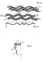
- Fig. 4 shows in the inflow region of the dialysate downstream of the channels 9 ', a deflecting element on the inner wall of the housing 1 in the form of a circumferentially circumferential or only near the individual channels or openings 9' formed paragraph 1 c, through which the inflowing dialysate radially inward is directed, as indicated by an arrow.
- This deflecting element 1c can be formed as a rib on the housing.
- a disk-shaped distributor element 10 is arranged centrally transversely to the longitudinal axis.
- the fluid flowing through the inlet conduit 6 will strike approximately the center of the distributor element 10 so that the flow will be evenly distributed radially outward from the center.
- the outer circumference of the distributor element 10, which has a distance from the sealing ring 8, is thereby flowed around uniformly.
- the distributor element 10 is provided on the side of the fluid flowing through the conduit 6 with a peg-shaped elevation 10a in the middle, which has a rounded end face. From the cone-shaped Rise 10 a extends a distributor surface 10 b to the peripheral edge of the distributor element 10.
- the distributor surface extends from the peg-shaped elevation 10a to the peripheral edge approximately at an angle of 90 ° to the longitudinal axis.
- the distributor surface can also extend in a flat-cone-shaped manner from the center to the outside, so that the angle on the inflow side between distributor surface 10b and the longitudinal axis is greater than 90 °.
- the peg-shaped elevation 10a can also be omitted, being replaced by the tip of the cone shape.
- the distributed flat surface 10b may also be formed slightly concave, so that it extends from a central elevation corresponding to 10a in a curved line to the circumference.
- spacers for example three distributed over the circumference are reproduced schematically, by means of which the distributor element 10 is held on the end face of the cap 5.
- the disc-shaped distributor element 10 may also be defined by elevations on the top and / or bottom or by spoke-like elements on the circumference in the cap 5 in its position, these locally provided increases or spokes are designed aerodynamically in cross section.
- the inlet line 6 facing side of the distributor element 10 may also be advantageously provided with spirally shaped ribs 10 d or depressions to impart a twist to the inflowing fluid.
- a structuring promoting the flow distribution may be provided, in addition to or even instead of the flat-conical shape.
- the distributor element 10 On the side facing the cut surface 4, the distributor element 10 has in the illustrated embodiment in Fig. 1 a flat-conical shape, wherein the tip has a small distance from the cut surface 4, so that the flow over the cut surface 4 from outside to inside evenly distributed and the inflow to the individual hollow fibers 2 radially inward is favored by the decreasing gap thickness.
- the flow velocity between the distributor element 10 and the cut surface 4 can also be influenced or uniformly designed so that the surface of the cut surface 4 is not flat, but flat cone-shaped.
- the wall of the cap 5 is shaped such that a gap thickness decreasing towards the periphery between distributor surface 10b and inner surface of the cap 5 results in order to make the speed distribution uniform.
- the gap thickness can therefore be made smaller by the cap shape and / or the shape of the distributor disc 10 radially outward.
- the hollow fiber bundle 2 has a different packing density over its length.
- the packing density is less than - seen in the axial direction - in the central region of the hollow fiber bundle.
- the packing density is expressed as a percentage of the bundle cross-sectional area occupied by hollow fibers. In the case of round hollow fiber cross sections, the theoretically maximum achievable packing density is 90.7%. Practically implemented packing densities are in the range of 40 to 60%.
- the packing density in the inlet region is about 30% to 40%, preferably 35% and in the central region of the hollow fiber bundle at about 45 to 55%, preferably 50%.
- the hollow fiber bundle has a packing density which is at least 5, preferably 10 smaller than the packing density in the middle region indicated in percent, so that for example at a packing density in the middle region of 50%, the packing density in the widened region at 40%, at most 45% lies.
- Fig. 1 shows, embedded in the potting compound 3 ends of the hollow fibers 2 are arranged so that within the potting compound 3 in the direction of the cut surface 4 results in a greater packing density than in the region of lowest packing density adjacent to the inside of the potting compound 3.
- the radially outer hollow fibers in the region of the potting compound 3 obliquely to the longitudinal axis of the dialysis filter so that they are packed closer to the cut surface 4 within the sealing ring 8 and on the opposite side of the potting compound 3 to close to the outer periphery of the potting compound 3.
- the bundle diameter is thus smaller at the cut surface 4 and already increases in the area of the potting compound.
- an angle ⁇ is reproduced, which reproduces the inclination angle, for example, of the radially outer hollow fiber to the longitudinal axis, said hollow fiber extending in the direction of the longitudinal axis, that is in a rotated by 90 ° view on the longitudinal axis.
- a higher packing density, in particular in the middle region of the hollow fiber bundle 2 can also be achieved by a different degree of twisting of the hollow fibers over their length.
- the per se round cross-sectional shape of the fibers to an oval sectional or projection surface perpendicular to the longitudinal axis.
- Fig. 1 shows - seen in the longitudinal direction - in the central region of the hollow fiber bundle 2, a twist of the hollow fibers about the longitudinal axis.
- the individual hollow fibers extend in the end region substantially untwisted to the potting compound, wherein they extend substantially along the longitudinal axis, while they are twisted or more twisted in the central region, forming an angle ⁇ to the longitudinal axis.
- this hollow fiber has a radial distance from the longitudinal axis, wherein it extends substantially in the direction thereof with an inclination to the longitudinal axis.
- the housing 1 is designed so that it adapts to the different packing density of the hollow fiber bundle 2.
- the housing 1 is therefore constricted in the central region 1a in the longitudinal direction, so that it surrounds the hollow fiber bundle 2 in the denser packing area, while the housing 1 in the end regions 1b and 1b 'bell-shaped or conically widens outwards.
- the inner wall of the housing in the end regions 1b and 1b 'with a larger diameter, the inner wall of the housing have a radial distance from the outer hollow fibers, as well as Fig. 1 shows.
- the exit region of the hollow fiber bundle 2 is also provided with a lower packing density in accordance with the configuration in the inlet region. This also achieves an improved radial flow to the outlet openings or channels 9 'in the potting compound 3'.
- the hollow fibers are in places in all areas of the varying packing density on the housing wall, wherein such a complete filling of the housing cross section in the range of different housing diameter can be achieved by the mechanical residual stresses corrugated hollow fibers. Due to the mechanical residual stress of corrugated hollow fibers spread apart and lie against the inner wall of the housing.
- the extension of the hollow fiber bundle 2 is expediently designed bell-shaped or cone-shaped, so that the dialysate initially flows radially and then in the axial direction along the hollow fibers over the length thereof.
- these are corrugated over their length and are preferably arranged twisted overall, at least in the middle region 1a of the housing, as this Fig. 1 schematically shows.
- the waveform of the individual hollow fibers or groups of hollow fibers is in Fig. 5 shown schematically, wherein various forms of corrugation are shown.
- Fig. 5a shows individual hollow fibers 2 with approximately the same wavelength, wherein the corrugations are arranged offset to one another in the longitudinal direction corresponding to a shift in the phase position.
- Fig. 5b shows two groups G 1 and G 2 , each with three corrugated hollow fibers, wherein the hollow fibers within a group G in the same phase position, while the adjacent group has a designated ⁇ 1 offset the phase position.
- hollow fibers form a group.
- one group has a predetermined offset of the phase angle to the adjacent group. This results in an ordered structure of the arrangement of corrugated hollow fibers within a bundle.
- the flow of dialysate runs along the hollow fibers, without this flow pattern is changed. Due to the offset corrugation of adjacent hollow fibers or adjacent hollow fiber groups G, this flow pattern is interrupted or turbulence of the flow of dialysate occurs around the hollow fibers, whereby the filter performance is improved.
- a predetermined amount of groups G having a predetermined offset ⁇ 1 of the corrugation is preferably formed relative to each other, the entire bundle being composed of a plurality of such quantities. In this way it is achieved that, at least in the range of an amount, the individual fiber groups have the predetermined displacement of the phase position and thus an optimum flow around the groups of hollow fibers is achieved.
- Fig. 5c shows a single hollow fiber 2 with varying corrugation over its length, wherein different wavelengths ⁇ 1 to ⁇ 3 are reproduced.
- the wavelength of the fiber corrugation may periodically change with a period at least twice the maximum wavelength.
Landscapes
- Chemical & Material Sciences (AREA)
- Chemical Kinetics & Catalysis (AREA)
- Engineering & Computer Science (AREA)
- Manufacturing & Machinery (AREA)
- Health & Medical Sciences (AREA)
- Urology & Nephrology (AREA)
- Water Supply & Treatment (AREA)
- External Artificial Organs (AREA)
- Separation Using Semi-Permeable Membranes (AREA)
Description
- Die Erfindung betrifft eine Filtervorrichtung nach dem Oberbegriff des Anspruchs 1 und insbesondere einen Dialysefilter.
- Ein Dialysefilter dieser Art ist aus
US-A- 5 489 413 bekannt, bei dem das Hohlfaserbündel ringförmig in einem Gehäuse um einen mittigen Hohlraum angeordnet ist. -
EP-A-0 798 034 beschreibt eine Hohlfaserfiltervorrichtung, bei der die Hohlfasern um einen mittigen, langgestreckten Dorn angeordnet sind, der Perforationen für den Durchtritt des Filtermediums aufweist. Die Hohlfasern sind schraubenlinienförmig gewunden in einem Gehäuse angeordnet und an den Enden in einer Vergussmasse gehalten. - Aufgabe der Erfindung ist es, eine Filtervorrichtung der eingangs angegebenen Art so auszubilden, dass die Filterleistung verbessert wird.
- Nach der Erfindung wird eine Verbesserung der Filterleistung dadurch erreicht, dass die Packungsdichte des Hohlfaserbündels über die Länge des Bündels variiert und das Hohlfaserbündel insbesondere im Ein- und/oder Ausströmbereich des Dialysats aufgeweitet ist, während die Packungsdichte im Mittelbereich des Hohlfaserbündels höher ist. Hierdurch wird ein möglichst ungehinderter radialer Fluss des Dialysats im aufgeweiteten Bereich des Bündels erreicht, sodass sich eine gleichmäßige Strömungsverteilung über den gesamten Bündelquerschnitt ergibt. Während aufgrund der geringeren Packungsdichte im Ein- und ggfs. auch im Ausströmbereich der radialen Strömung ein geringer Strömungswiderstand entgegengesetzt wird, wird im Hauptteil des Filters durch die höhere Packungsdichte der Hohlfasern eine gleichmäßige Umströmung der einzelnen Hohlfasern in Längsrichtung gewährleistet.Hierdurch wird ein optimaler Stoffabtransport vor allem auch in den Ein- und Ausströmbereichen und damit eine Verbesserung der Filterleistung erzielt.
- Die Erfindung wird beispielsweise anhand der Zeichnung näher erläutert. Es zeigen
- Fig. 1
- einen schematischen Längsschnitt durch einen Dialysefilter,
- Fig. 2
- eine Draufsicht auf die Schnittfläche des Hohlfaserbündels mit Dichtung,
- Fig. 3
- einen Querschnitt durch ein Verteilerelement und eine Draufsicht,
- Fig. 4
- Ablenkelemente im Einströmbereich des Fluids zwischen die Hohlfasern, und
- Fig. 5
- schematisch Varianten der Wellung der Hohlfasern im Bündel.
-
Fig. 1 zeigt in einem Längsschnitt einen Dialysator mit einem allgemein rohrförmigen Gehäuse 1, das an den Stirnseiten durch Kappen 5 und 5' geschlossen ist. In dem Gehäuse 1 ist ein Bündel aus semi-permeablen Hohlfasern 2 durch zwei scheibenförmige Blöcke 3 und 3' einer Vergussmasse positioniert, deren Umfang auf dem Innenumfang des rohrförmigen Gehäuses 1 anliegt und in die die Enden der einzelnen Hohlfasern 2 des Bündels fluiddicht eingebettet sind. Die jeweilige Außenseite der Vergussmasse 3 bzw. 3' bildet eine ebene Schnittfläche 4 bzw. 4' der Hohlfasern quer zur Längsachse des Gehäuses mit Öffnung zum Innern der Hohlfasern. - Bei dem dargestellten Ausführungsbeispiel in
Fig. 1 liegt die Schnittebene 4 im Wesentlichen auf der Höhe des Randes des Gehäuses 1, wobei sich die Kappen 5 über den Endbereich des Gehäuses 1 erstrecken und gegenüber dem Gehäuse abgedichtet sind. Die Schnittebene 4 kann aber auch versetzt zum Rand des Gehäuses angeordnet sein. - Die Kappen 5 und 5' am Gehäuse 1 sind jeweils mittig mit einer Einlassleitung 6 bzw. einer Auslassleitung 6' versehen, die im Wesentlichen längs der Längsache des rohrförmigen Gehäuses 1 verläuft. Bei einem Dialysator wird durch die Leitung 6 Blut zugeführt und über die Leitung 6' abgeführt. Dialysat wird im Gegenstrom durch eine radial in die Kappe 5 mündende Leitung 7' zugeführt und durch eine Leitung 7 abgeführt. Die Strömungsrichtung ist durch Pfeile in
Fig. 1 wiedergegeben. - Mit 8 und 8' ist ein Dichtungsring zwischen Kappe 5 und Schnittfläche 4 bezeichnet, der zwei Fluidkammern im Dialysator voneinander trennt, eine erste Fluidkammer, die die Einlassleitung 6 und die Auslassleitung 6' mit dem zentralen Bereich in den Kappen 5 und 5' sowie das Innere der Hohlfasern 2 umfasst, und eine zweite Fluidkammer, die die Leitungen 7 und 7' für das Dialysat mit dem Strömungsbereich außerhalb des Dichtungsringes 8 in den Kappen und den Innenraum des Gehäuses 1 zwischen den einzelnen Hohlfasern 2 umfasst.
- Außerhalb des Dichtungsringes 8' sind in der Vergussmasse 3' im Wesentlichen axial verlaufende Kanäle 9' vorzugsweise ungleichmäßig über den Umfang verteilt angeordnet, wie
Fig. 2 zeigt, durch die das über die Einlassleitung 7' einströmende Dialysat in die zweite Fluidkammer zwischen den Hohlfasern eingeleitet wird. In gleicher Weise sind im Austrittsbereich des Dialysats Fluidkanäle 9 außerhalb des Dichtungsringes 8 auf dem Umfang der Vergussmasse 3 verteilt angeordnet. - Die im Wesentlichen axial verlaufenden Kanäle 9', die in
Fig. 2 mit einem runden Querschnitt dargestellt sind, aber auch einem langgestreckten Rechteckquerschnitt haben können, haben im Einlaufbereich vorzugsweise eine sich in Strömungsrichtung verjüngende Form, um die Strömungsverteilung im Einlaufbereich zu unterstützen. Auf der Austrittsseite sind die Kanäle 9 aus herstellungstechnischen Gründen in gleicher Weise ausgebildet. In diesem Bereich können sie auch eine durchgehend gleiche Querschnittsform haben. - Die auf dem Umfang der Vergussmasse 3' vorgesehenen Kanäle 9' können in ihrem Abstand und/oder Querschnitt unterschiedlich gestaltet sein, um das Strömungsprofil insbesondere im Einlaufbereich zu beeinflussen.
Fig. 2 zeigt durch einen Pfeil das durch die Einlassleitung 7' in radialer Richtung einströmende Dialysat. Damit nicht ein Hauptteil des Dialysats durch die Kanäle 9' nahe der Einlassleitung 7' in die Fluidkammer zwischen den Hohlfasern einströmt, während an den diametral gegenüberliegenden Kanälen 9' weniger Dialysat zuströmen würde, sind die Kanäle 9' auf der der Einlassleitung 7' gegenüberliegenden Seite dichter längs des Umfangs angeordnet als im Bereich der Einlassleitung 7'. Hierdurch wird die Zuströmung des Dialysats in die Fluidkammer um die Hohlfasern gleichmäßiger über den Umfang verteilt. -
Fig. 4 zeigt im Einströmbereich des Dialysats stromab von den Kanälen 9' ein Ablenkelement an der Innenwand des Gehäuses 1 in Form eines über den Umfang umlaufenden oder nur nahe den einzelnen Kanälen bzw. Durchbrüchen 9' ausgebildeten Absatzes 1 c, durch den das einströmende Dialysat radial nach innen gelenkt wird, wie dies durch einen Pfeil angedeutet ist. Dieses Ablenkelement 1c kann als Rippe am Gehäuse angeformt sein. - In der mit der Einlassleitung 6 versehenen Kappe 5 ist ein scheibenförmiges Verteilerelement 10 mittig quer zur Längsachse angeordnet. Das durch die Einlassleitung 6 zuströmende Fluid trifft etwa auf die Mitte des Verteilerelementes 10, sodass die Strömung von der Mitte aus radial nach außen gleichmäßig verteilt wird. Der Außenumfang des Verteilerelementes 10, der einen Abstand von dem Dichtungsring 8 hat, wird hierdurch gleichmäßig umströmt. Zur Verbesserung der Verteilung der Strömung zum Umfang hin ist das Verteilerelement 10 auf der Seite des durch die Leitung 6 zuströmenden Fluids mit einer zapfenförmigen Erhöhung 10a in der Mitte versehen, die eine abgerundete Stirnfläche aufweist. Von der zapfenförmigen Erhöhung 10a erstreckt sich eine Verteilerfläche 10b zum Umfangsrand des Verteilerelementes 10. Bei dem Ausführungsbeispiel nach
Fig. 3 erstreckt sich die Verteilerfläche von der zapfenförmigen Erhöhung 10a zum Umfangsrand etwa in einem Winkel von 90° zur Längsachse. Die Verteilerfläche kann auch flach-kegelförmig von der Mitte nach außen verlaufen, sodass der Winkel auf der Zuströmseite zwischen Verteilerfläche 10b und Längsachse größer als 90° ist. Bei einer solchen flach-kegelförmigen Gestaltung kann die zapfenförmige Erhöhung 10a auch entfallen, wobei sie durch die Spitze der Kegelform ersetzt wird. - Bei einer solchen Ausgestaltung in Verbindung mit der in
Fig. 1 und 3 wiedergegebenen flachen Kegelform auf der Unterseite der Verteilerscheibe ergibt sich ein insgesamt etwa diskusförmiges Verteilerelement 10. Die Verteilerfläche 10b kann auch leicht konkav gewölbt ausgebildet sein, sodass sie sich von einer mittigen Erhöhung entsprechend 10a in einer Bogenlinie zum Umfang erstreckt. - Bei 10c sind schematisch über den Umfang verteilte Abstandhalter (beispielsweise drei) wiedergegeben, durch die das Verteilerelement 10 an der Stirnseite der Kappe 5 gehalten wird. Das scheibenförmige Verteilerelement 10 kann auch durch Erhebungen auf der Ober- und/oder Unterseite oder auch durch speichenartige Elemente auf dem Umfang in der Kappe 5 in seiner Lage festgelegt sein, wobei diese stellenweise vorgesehenen Erhöhungen oder Speichen im Querschnitt strömungsgünstig gestaltet sind.
- Wie
Fig. 3b zeigt, kann die der Einlassleitung 6 zugewandte Seite des Verteilerelementes 10 vorteilhafterweise auch mit spiralförmig gestalteten Rippen 10d oder Vertiefungen versehen sein, um dem zuströmenden Fluid einen Drall zu erteilen. In gleicher Weise kann auf der der Schnittfläche 4 zugewandten Seite eine die Strömungsverteilung begünstigende Strukturierung vorgesehen werden, zusätzlich zu der flach-kegelförmigen Gestalt oder auch anstelle von dieser. - Auf der der Schnittfläche 4 zugewandten Seite hat das Verteilerelement 10 bei dem dargestellten Ausführungsbeispiel in
Fig. 1 eine flach-kegelförmige Gestalt, wobei die Spitze einen geringen Abstand von der Schnittfläche 4 hat, sodass die Strömung über die Schnittfläche 4 von außen nach innen gleichmäßig verteilt und die Zuströmung zu den einzelnen Hohlfasern 2 radial innen durch die kleiner werdende Spaltdicke begünstigt wird. - Die Strömungsgeschwindigkeit zwischen Verteilerelement 10 und Schnittfläche 4 kann auch dadurch beeinflusst bzw. gleichmäßig gestaltet werden, dass die Oberfläche der Schnittfläche 4 nicht eben, sondern flach-kegelförmig ausgebildet wird.
- Bei dem Ausführungsbeispiel nach
Fig. 1 ist die Wand der Kappe 5 so geformt, dass sich eine zum Umfang hin kleiner werdende Spaltdicke zwischen Verteilerfläche 10b und Innenfläche der Kappe 5 ergibt, um die Geschwindigkeitsverteilung gleichmäßig zu gestalten. Dabei ist die Spaltform vorzugsweise so gestaltet, dass die Strömungsgeschwindigkeit v des zuströmenden Fluids radial nach außen langsamer abnimmt als entsprechend der Formel v = const./r, die sich bei einer konstanten Spaltdicke ergeben würde. - Die Spaltdicke kann also durch die Kappenform und/oder die Formgebung der Verteilerscheibe 10 radial nach außen kleiner werdend ausgebildet werden.
- Das Hohlfaserbündel 2 hat eine über seine Länge unterschiedliche Packungsdichte. Insbesondere ist im Zulaufbereich bei 1b die Packungsdichte geringer als - in axialer Richtung gesehen - im Mittelbereich des Hohlfaserbündels. Die Packungsdichte ist in Prozent ausgedrückt der Anteil der Bündelquerschnittsfläche, der durch Hohlfasern ausgefüllt wird. Im Falle runder Hohlfaserquerschnitte ist die theoretisch maximal erreichbare Packungsdichte 90,7 %. Praktisch realisierte Packungsdichten liegen im Bereich von 40 bis 60 %. Vorzugsweise liegt die Packungsdichte im Zulaufbereich bei etwa 30 % bis 40 %, vorzugsweise bei 35 % und im Mittelbereich des Hohlfaserbündels bei etwa 45 bis 55 %, bevorzugt 50 %.
- Im aufgeweiteten Bereich hat das Hohlfaserbündel eine Packungsdichte, die wenigstens um 5, vorzugsweise 10 kleiner ist als die in Prozent angegebene Packungsdichte im Mittelbereich, sodass beispielsweise bei einer Packungsdichte im Mittelbereich von 50 % die Packungsdichte im aufgeweiteten Bereich bei 40 %, höchstens bei 45 % liegt.
- Durch die geringere Packungsdichte im Zulaufbereich des Dialysats ergibt sich eine verbesserte radiale Strömung zwischen die Hohlfasern. Hierdurch wird erreicht, dass das Dialysat bereits im Einlaufbereich vollständig mit den Filterflächen der Hohlfasern in Kontakt kommt und dadurch die Länge der Hohlfasern hinsichtlich Filterwirkung voll ausgenutzt wird. Im anschließend dichteren Bereich ergibt sich eine Strömung in Längsrichtung bei gleichmäßiger Umströmung der einzelnen Fasern ohne Kanalbildung zwischen den Hohlfasern.
- Wie
Fig. 1 zeigt, sind die in die Vergussmasse 3 eingebetteten Enden der Hohlfasern 2 so angeordnet, dass sich innerhalb der Vergussmasse 3 in Richtung auf die Schnittfläche 4 eine größere Packungsdichte ergibt als im Bereich niedrigster Packungsdichte angrenzend an die Innenseite der Vergussmasse 3. Mit anderen Worten verlaufen vor allem die radial äußeren Hohlfasern im Bereich der Vergussmasse 3 schräg zur Längsachse des Dialysefilters, sodass sie an der Schnittfläche 4 innerhalb des Dichtungsringes 8 dichter gepackt sind und auf der gegenüberliegenden Seite der Vergussmasse 3 sich bis nahe an den Außenumfang der Vergussmasse 3 aufweiten. Der Bündeldurchmesser ist somit an der Schnittfläche 4 kleiner und vergrößert sich bereits im Bereich der Vergussmasse. - In
Fig. 1 ist ein Winkel α wiedergegeben, der den Neigungswinkel beispielsweise der radial äußeren Hohlfaser zur Längsachse wiedergibt, wobei diese Hohlfaser in Richtung der Längsachse verläuft, also in einer um 90° verdrehten Ansicht auf der Längsachse liegt. - Eine höhere Packungsdichte insbesondere im Mittelbereich des Hohlfaserbündels 2 kann auch durch eine unterschiedlich starke Verdrillung der Hohlfasern über ihre Länge erreicht werden. Hierbei wird die an sich runde Querschnittsform der Fasern zu einer ovalen Schnitt- bzw. Projektionsfläche senkrecht zur Längsachse.
Fig. 1 zeigt - in Längsrichtung gesehen - im Mittelbereich des Hohlfaserbündels 2 eine Verdrillung der Hohlfasern um die Längsachse. Mit anderen Worten verlaufen die einzelnen Hohlfasern im Endbereich im Wesentlichen unverdrillt auf die Vergussmasse zu, wobei sie im Wesentlichen längs der Längsachse verlaufen, während sie im Mittelbereich verdrillt oder stärker verdrillt sind, wobei sie einen Winkel β zur Längsachse bilden. Deutlich wird dies beispielsweise bei der schematischen Darstellung inFig. 1 an der im Einströmbereich in der Mitte liegenden Hohlfaser 2a, die im Einlaufbereich im Wesentlichen sich längs der Längsachse erstreckt, worauf sie im Mittelbereich einen schrägen Verlauf zur Längsachse einnimmt und sich um diese herum erstreckt, sodass sie im Umfangsbereich der Vergussmasse 3' unter der Zeichenebene mündet. Im Auslaufbereich hat diese Hohlfaser einen radialen Abstand von der Längsachse, wobei sie im Wesentlichen in deren Richtung verläuft mit einer Neigung zur Längsachse hin. - Nach einer vorteilhaften Ausgestaltung wird das Gehäuse 1 so gestaltet, dass es sich an die unterschiedliche Packungsdichte des Hohlfaserbündels 2 anpasst. Das Gehäuse 1 ist deshalb im Mittelbereich 1a in Längsrichtung gesehen eingeschnürt, sodass es das Hohlfaserbündel 2 im dichteren Packungsbereich umschließt, während sich das Gehäuse 1 in den Endbereichen 1b und 1b' glocken- oder kegelförmig nach außen erweitert. Dabei kann in den Endbereichen 1b und 1b' mit größerem Durchmesser die Innenwand des Gehäuses einen radialen Abstand von den äußeren Hohlfasern haben, wie dies auch
Fig. 1 zeigt. - Vorzugsweise ist auch der Austrittsbereich des Hohlfaserbündels 2 mit einer geringeren Pakkungsdichte versehen entsprechend der Ausgestaltung im Einlaufbereich. Auch hierdurch wird eine verbesserte radiale Strömung zu den Austrittsöffnungen bzw. Kanälen 9' in der Vergussmasse 3' erreicht.
- Bevorzugt liegen die Hohlfasern in allen Bereichen der variierenden Packungsdichte an der Gehäusewand stellenweise an, wobei ein derartiges vollständiges Ausfüllen des Gehäusequerschnitts im Bereich unterschiedlicher Gehäusedurchmesser durch die mechanische Eigenspannungen gewellter Hohlfasern erreicht werden kann. Durch die mechanische Eigenspannung von gewellten Hohlfasern spreizen sich diese auseinander und liegen an der Innenwand des Gehäuses an.
- Die Erweiterung des Hohlfaserbündels 2 wird zweckmäßigerweise glockenförmig oder kegelförmig gestaltet, damit das Dialysat zunächst radial und dann in Achsrichtung längs der Hohlfasern über deren Länge strömt.
- Zur Verbesserung des Kontakts der Dialysatströmung mit den Hohlfasern sind diese über ihre Länge gewellt und vorzugsweise insgesamt zumindest im Mittelbereich 1a des Gehäuses verdrillt angeordnet, wie dies
Fig. 1 schematisch zeigt. Die Wellenform der einzelnen Hohlfasern bzw. Gruppen von Hohlfasern ist inFig. 5 schematisch wiedergegeben, wobei verschiedene Formen der Wellung gezeigt sind. Durch die Wellung der Hohlfasern wird einerseits erreicht, dass die Hohlfasern nur an einzelnen Stellen aneinanderliegen und damit ihre maximale Oberfläche für die Filterwirkung zur Verfügung steht, und andererseits, dass durch Verwirbelung der Umströmung der Hohlfasern der Stoffaustausch verbessert wird. Zudem verhindert die Faserwellung auch die Kanalbildung zwischen den Hohlfasern, d. h. Bereiche zu geringer Packungsdichte, durch die das Dialysat bevorzugt strömt, ohne zur Filterleistung beizutragen. -
Fig. 5a zeigt einzelne Hohlfasern 2 mit etwa gleicher Wellenlänge, wobei die Wellungen in Längsrichtung versetzt zueinander angeordnet sind entsprechend einer Verschiebung der Phasenlage. -
Fig. 5b zeigt zwei Gruppen G1 und G2 mit jeweils drei gewellten Hohlfasern, wobei die Hohlfasern innerhalb einer Gruppe G in der gleichen Phasenlage verlaufen, während die benachbarte Gruppe eine mit Φ1 bezeichnete Versetzung der Phasenlage aufweist. Vorzugsweise bilden 2 bis 20, vorzugsweise 8, Hohlfasern eine Gruppe. Zumindest in einer bestimmten Menge von Fasergruppen G weist eine Gruppe eine vorgegebene Versetzung der Phasenlage zur benachbarten Gruppe auf. Hierdurch ergibt sich eine geordnete Struktur der Anordnung der gewellten Hohlfasern innerhalb eines Bündels. Zwischen parallel zueinanderliegenden Hohlfasern oder auch bei gleicher Phasenlage nebeneinanderliegender gewellter Hohlfasern, wie dies innerhalb einer Gruppe G der Fall ist, verläuft die Strömung des Dialysats längs der Hohlfasern, ohne dass dieses Strömungsmuster verändert wird. Durch die versetzte Wellung benachbarter Hohlfasern oder benachbarter Hohlfasergruppen G wird dieses Strömungsmuster unterbrochen bzw. tritt eine Verwirbelung der Strömung des Dialysats um die Hohlfasern auf, wodurch die Filterleistung verbessert wird. - Bei der Herstellung eines Hohlfaserbündels wird bevorzugt eine vorgegebene Menge von Gruppen G mit einer vorgegebenen Versetzung Φ1 der Wellung relativ zueinander ausgebildet, wobei das gesamte Bündel aus mehreren solchen Mengen zusammengesetzt wird. Auf diese Weise wird erreicht, dass zumindest im Bereich einer Menge die einzelnen Fasergruppen die vorgegebene Versetzung der Phasenlage haben und damit eine optimale Umströmung der Gruppen von Hohlfasern erreicht wird.
-
Fig. 5c zeigt eine einzelne Hohlfaser 2 mit über ihre Länge variierender Wellung, wobei verschiedene Wellenlängen λ1 bis λ3 wiedergegeben sind. - Nach einer anderen Ausgestaltung kann sich die Wellenlänge der Faserwellung periodisch mit einer Periode verändern, die mindestens doppelt so groß ist wie die größte Wellenlänge.
Claims (5)
- Filtervorrichtung, insbesondere zur Entfernung von Substanzen aus Blut oder anderen Körperflüssigkeiten, umfassend- ein Bündel aus semi-permeablen Hohlfasern (2),- die an ihren Enden in einer Vergussmasse (3) eingebettet und gehalten sind, und- ein rohrförmiges Gehäuse (1), das das Hohlfaserbündel umgibt,- wobei Ein- und Auslassleitungen (6, 7; 6', 7') an den Gehäuseenden mit den in dem Gehäuse ausgebildeten getrennten Fluidräumen verbunden sind,wobei das Hohlfaserbündel (2) eine über seine Länge derart variierende Packungsdichte aufweist, dass das Hohlfaserbündel zumindest im Einströmbereich des die Hohlfasern umgebenden Fluidraumes eine niedrigere Packungsdichte aufweist als im anschließenden Mittelbereich,
dadurch gekennzeichnet,
daß im Bereich der in die Vergussmasse (3) eingebetteten Faserenden die Packungsdichte höher ist als in den Bereichen niedrigster Packungsdichte angrenzend an die Vergussmasse. - Filtervorrichtung nach Anspruch 1, wobei im Ausströmbereich des die Hohlfasern umgebenden Fluidraumes im Wesentlichen die gleiche Packungsdichte vorgesehen ist wie im Einströmbereich.
- Filtervorrichtung nach Anspruch 1 oder 2, wobei das Hohlfaserbündel in den Bereichen geringerer Packungsdichte kegel- oder glockenförmig aufgeweitet ist.
- Filtervorrichtung nach einem der vorhergehenden Ansprüche, wobei die in Längsrichtung des Hohlfaserbündels variierende Packungsdichte mindestens zum Teil durch eine unterschiedlich starke Verdrillung der Hohlfasern (2) in den verschiedenen Bereichen erreicht wird.
- Filtervorrichtung nach einem der vorhergehenden Ansprüche, wobei die Hohlfasern eine wellenförmige Struktur haben und in den Endbereichen und im Mittelbereich über die Länge des Bündels an der Gehäusewand mindestens stellenweise anliegen.
Priority Applications (4)
| Application Number | Priority Date | Filing Date | Title |
|---|---|---|---|
| AT05008649T ATE500880T1 (de) | 2005-04-20 | 2005-04-20 | Dialysefilter |
| EP05008649A EP1714692B1 (de) | 2005-04-20 | 2005-04-20 | Dialysefilter |
| DE502005011077T DE502005011077D1 (de) | 2005-04-20 | 2005-04-20 | Dialysefilter |
| US11/406,898 US20060243653A1 (en) | 2005-04-20 | 2006-04-19 | Dialysis filter |
Applications Claiming Priority (1)
| Application Number | Priority Date | Filing Date | Title |
|---|---|---|---|
| EP05008649A EP1714692B1 (de) | 2005-04-20 | 2005-04-20 | Dialysefilter |
Publications (2)
| Publication Number | Publication Date |
|---|---|
| EP1714692A1 EP1714692A1 (de) | 2006-10-25 |
| EP1714692B1 true EP1714692B1 (de) | 2011-03-09 |
Family
ID=35094442
Family Applications (1)
| Application Number | Title | Priority Date | Filing Date |
|---|---|---|---|
| EP05008649A Expired - Lifetime EP1714692B1 (de) | 2005-04-20 | 2005-04-20 | Dialysefilter |
Country Status (4)
| Country | Link |
|---|---|
| US (1) | US20060243653A1 (de) |
| EP (1) | EP1714692B1 (de) |
| AT (1) | ATE500880T1 (de) |
| DE (1) | DE502005011077D1 (de) |
Families Citing this family (25)
| Publication number | Priority date | Publication date | Assignee | Title |
|---|---|---|---|---|
| FR2909008B1 (fr) * | 2006-11-27 | 2009-11-27 | Vaslin Bucher | Dispositif pour empecher la formation de depots aux entrees des membranes tubulaires ou capillaires d'un module de filtration tangentielle. |
| FR2920099B1 (fr) * | 2007-08-24 | 2019-12-13 | Societe Techniques Industrielles Appliquees-Tia | Conception realisation de disque adapte au decolmatage dynamique permanent des membranes planes de filtration tangentielle. |
| US20100125235A1 (en) * | 2008-06-16 | 2010-05-20 | Triaxis Medical Devices, Inc. | Blood Treatment Apparatus Having Branched Flow Distribution |
| DE102009017413A1 (de) | 2009-04-14 | 2010-11-18 | Fresenius Medical Care Deutschland Gmbh | Filtervorrichtung und Verfahren zur Herstellung einer Filtervorrichtung |
| WO2010128044A1 (de) * | 2009-05-04 | 2010-11-11 | Fresenius Medical Care Deutschland Gmbh | Vorrichtung und verfahren zur herstellung eines hohlfaserbündels mit gewellten, phasenvershobenen hohlfasern |
| BR112012005733A2 (pt) * | 2009-09-14 | 2017-05-30 | Univ Columbia | métodos de canal de fluido de filtro de sangue, dispositivos e sistemas. |
| DE102011018925B4 (de) | 2011-04-28 | 2015-03-26 | Hermann Reuschenbach | Hohlfaser-Anordnung für Dialysatoren und ähnliche Filtervorrichtungen und Verfahren zu ihrer Herstellung |
| EP2762180A4 (de) * | 2011-09-30 | 2015-05-13 | Toray Industries | Reinigungssäule und verfahren zur herstellung der reinigungssäule |
| DE102012204705A1 (de) * | 2012-03-23 | 2013-09-26 | Raumedic Ag | Wärmetauscher für einen Oxygenator und Verfahren zur Herstellung eines derartigen Wärmetauschers |
| JP5829227B2 (ja) * | 2012-09-28 | 2015-12-09 | 富士フイルム株式会社 | 酸性ガス分離モジュール、酸性ガス分離装置、及びテレスコープ防止板 |
| DE102013106247A1 (de) | 2013-06-14 | 2014-12-18 | B. Braun Avitum Ag | Filtervorrichtung für Blut und dergleichen Körperflüssigkeiten |
| EP2815807A1 (de) * | 2013-06-20 | 2014-12-24 | Gambro Lundia AB | Hohlfaserdialysatoren |
| WO2015114400A1 (en) * | 2014-02-03 | 2015-08-06 | Eurosider S.A.S.Di Milli Ottavio & C. | Module for separating nitrogen with hollow-fibre membrane |
| WO2015153370A2 (en) | 2014-03-29 | 2015-10-08 | Labib Mohamed E | Blood processing cartridges and systems, and methods for extracorporeal blood therapies |
| JP6728743B2 (ja) * | 2015-03-31 | 2020-07-22 | 東レ株式会社 | 浄化カラム |
| US10426884B2 (en) | 2015-06-26 | 2019-10-01 | Novaflux Inc. | Cartridges and systems for outside-in flow in membrane-based therapies |
| WO2017048224A1 (en) * | 2015-09-14 | 2017-03-23 | Labib Mohamed E | Cartridges and systems for outside-in flow in membrane-based therapies |
| EP3352888B8 (de) | 2015-09-24 | 2022-01-12 | Princeton Trade and Technology Inc. | Kartuschen für hohlfasermembranbasierte therapien |
| DE102015116787A1 (de) * | 2015-10-02 | 2017-04-06 | B. Braun Avitum Ag | Hohlfasermembran mit periodischer Querschnittsänderung |
| DE102016002440A1 (de) | 2016-03-01 | 2017-09-07 | Fresenius Medical Care Deutschland Gmbh | Hohlfasermembran mit dreidimensionaler Lockung |
| DE102016003611A1 (de) * | 2016-03-29 | 2017-10-05 | Enmodes Gmbh | Vorrichtung für den Stoffaustausch und Verfahren zur Herstellung |
| KR102252042B1 (ko) * | 2017-09-26 | 2021-05-13 | 코오롱인더스트리 주식회사 | 조립형 카트리지 블록 및 이를 포함하는 중공사막 모듈 |
| EP3495033A1 (de) * | 2017-12-11 | 2019-06-12 | Gambro Lundia AB | Hohlfaserdialysator |
| CN109200367A (zh) * | 2018-11-05 | 2019-01-15 | 威海威高血液净化制品有限公司 | 透析器、透析装置及透析器制造方法 |
| CN110575579A (zh) * | 2019-09-23 | 2019-12-17 | 中国科学技术大学 | 一种改善血液流动的透析增强型血液透析器 |
Family Cites Families (19)
| Publication number | Priority date | Publication date | Assignee | Title |
|---|---|---|---|---|
| US4219426A (en) | 1976-03-19 | 1980-08-26 | Organon Teknika B.V. | Dialysis device |
| DE2646358C2 (de) * | 1976-10-14 | 1982-05-13 | Dr. Eduard Fresenius, Chemisch-pharmazeutische Industrie KG Apparatebau KG, 6380 Bad Homburg | Hohlfaserdialysator |
| US4239729A (en) * | 1978-06-06 | 1980-12-16 | Terumo Corporation | Oxygenator |
| US4269712A (en) | 1979-05-14 | 1981-05-26 | Cordis Dow Corp. | Hollow fiber separatory element and method of making same |
| DE3301268A1 (de) * | 1983-01-17 | 1984-07-26 | Akzo Gmbh, 5600 Wuppertal | Verfahren und vorrichtung zum herstellen von hohlfadenbuendeln |
| JPS6054711A (ja) | 1983-09-05 | 1985-03-29 | Toray Ind Inc | 中空糸型膜分離装置の製造方法 |
| US4876066A (en) * | 1986-07-14 | 1989-10-24 | Baxter International Inc. | Integrated membrane oxygenator, heat exchanger and reservoir |
| DE3711695A1 (de) * | 1987-04-07 | 1988-10-27 | Akzo Gmbh | Verteilerkappe fuer eine einrichtung zur extrakorporalen behandlung von blut oder blutbestandteilen |
| DE3879218T2 (de) * | 1987-09-21 | 1993-07-22 | Terumo Corp | Medizinisches instrument und verfahren zur herstellung. |
| US5169529A (en) * | 1991-04-22 | 1992-12-08 | Hoechst Celanese Corporation | Liquid membrane modules with minimal effective membrane thickness and methods of making the same |
| US5299749A (en) * | 1992-03-24 | 1994-04-05 | Air Products And Chemicals, Inc. | Method of winding hollow fiber membranes |
| DE59310128D1 (de) * | 1992-03-27 | 2001-01-11 | Akzo Nobel Nv | Hohlfadenbündel sowie Verfahren zu seiner Herstellung |
| US5489413A (en) | 1992-11-03 | 1996-02-06 | Cobe Laboratories, Inc. | Hollow fiber blood oxygenator |
| US5598874A (en) * | 1995-08-11 | 1997-02-04 | Mg Generon, Inc. | Loom processing of hollow fiber membranes |
| US5837033A (en) | 1996-03-29 | 1998-11-17 | Praxair Technology, Inc. | Hollow fiber membrane separation apparatus |
| US6322703B1 (en) * | 1999-04-20 | 2001-11-27 | Asahi Kasei Kabushiki Kaisha | Method for purifying aqueous suspension |
| US6638479B1 (en) * | 1999-10-11 | 2003-10-28 | Medtronic, Inc. | Variable packing density in hollow fiber device |
| EP1432955A4 (de) * | 2001-10-01 | 2006-05-17 | Entegris Inc | Thermoplastischer wärmetauscher und verfahren zu dessen herstellung |
| AU2002953111A0 (en) * | 2002-12-05 | 2002-12-19 | U. S. Filter Wastewater Group, Inc. | Mixing chamber |
-
2005
- 2005-04-20 DE DE502005011077T patent/DE502005011077D1/de not_active Expired - Lifetime
- 2005-04-20 EP EP05008649A patent/EP1714692B1/de not_active Expired - Lifetime
- 2005-04-20 AT AT05008649T patent/ATE500880T1/de active
-
2006
- 2006-04-19 US US11/406,898 patent/US20060243653A1/en not_active Abandoned
Also Published As
| Publication number | Publication date |
|---|---|
| US20060243653A1 (en) | 2006-11-02 |
| DE502005011077D1 (de) | 2011-04-21 |
| EP1714692A1 (de) | 2006-10-25 |
| ATE500880T1 (de) | 2011-03-15 |
Similar Documents
| Publication | Publication Date | Title |
|---|---|---|
| EP1714692A1 (de) | Dialysefilter | |
| DE68923975T2 (de) | Säulenfilter mit Bündeln langer Fasern. | |
| DE60125052T2 (de) | Spiralförmig gefaltete filterpatronen | |
| DE112012005379B4 (de) | Fliehkraftabscheider und Filteranordnung | |
| DE60023607T2 (de) | Querstromfiltrationsmembran und Verfahren zu ihrer Herstellung | |
| EP3795233B1 (de) | Luftfilterelement | |
| CH681280A5 (de) | ||
| EP3436183B1 (de) | Hohlfasermembranvorrichtung für den stoffaustausch und verfahren zur herstellung | |
| EP1574244B1 (de) | Endkappe für eine Filtervorrichtung | |
| EP0973596B1 (de) | Filtervorrichtung mit filterscheiben | |
| EP2282825A1 (de) | Filtersystem | |
| EP0742053A1 (de) | Hydrodynamische Düse für die Reinigung von Rohren und Kanälen | |
| EP2991748A1 (de) | Filterelement | |
| DE69736485T2 (de) | Filtersektorvorrichtung für eine rotierende filterscheibe | |
| EP3278855B1 (de) | Filteranlage | |
| EP1380332B1 (de) | Anschwemmfilterkerze, Anschwemmfilter und Verwendung einer Filterkerze | |
| DE69835655T2 (de) | Monolithisches Keramikfilter | |
| DE69926256T2 (de) | Monolitischer, poröser träger für filterelement und filterelement | |
| EP1243301B1 (de) | Filterkerze | |
| EP1761327B1 (de) | Membranmodul für einen tauchbetrieb | |
| DE20304489U1 (de) | Regenwasser-Ablaufleitung | |
| DE10244292B4 (de) | Verwendung von Filterelementen in Rückspülfiltern | |
| DE3329525A1 (de) | Filter mit einem oder mehreren filterscheiben aufweisende filtereinheiten | |
| DE102015223328A1 (de) | Filterelement, Verfahren zur Fertigung des Filterelements, und Filter mit dem Filterelement | |
| DE102007006811A1 (de) | Vorrichtung zum Filtrieren einer thermoplastischen Kunststoffschmelze |
Legal Events
| Date | Code | Title | Description |
|---|---|---|---|
| PUAI | Public reference made under article 153(3) epc to a published international application that has entered the european phase |
Free format text: ORIGINAL CODE: 0009012 |
|
| AK | Designated contracting states |
Kind code of ref document: A1 Designated state(s): AT BE BG CH CY CZ DE DK EE ES FI FR GB GR HU IE IS IT LI LT LU MC NL PL PT RO SE SI SK TR |
|
| AX | Request for extension of the european patent |
Extension state: AL BA HR LV MK YU |
|
| 17P | Request for examination filed |
Effective date: 20070323 |
|
| AKX | Designation fees paid |
Designated state(s): AT BE BG CH CY CZ DE DK EE ES FI FR GB GR HU IE IS IT LI LT LU MC NL PL PT RO SE SI SK TR |
|
| 17Q | First examination report despatched |
Effective date: 20071005 |
|
| RAP1 | Party data changed (applicant data changed or rights of an application transferred) |
Owner name: B. BRAUN AVITUM AG |
|
| GRAP | Despatch of communication of intention to grant a patent |
Free format text: ORIGINAL CODE: EPIDOSNIGR1 |
|
| GRAS | Grant fee paid |
Free format text: ORIGINAL CODE: EPIDOSNIGR3 |
|
| GRAA | (expected) grant |
Free format text: ORIGINAL CODE: 0009210 |
|
| AK | Designated contracting states |
Kind code of ref document: B1 Designated state(s): AT BE BG CH CY CZ DE DK EE ES FI FR GB GR HU IE IS IT LI LT LU MC NL PL PT RO SE SI SK TR |
|
| REG | Reference to a national code |
Ref country code: GB Ref legal event code: FG4D Free format text: NOT ENGLISH |
|
| REG | Reference to a national code |
Ref country code: CH Ref legal event code: EP |
|
| REG | Reference to a national code |
Ref country code: IE Ref legal event code: FG4D Free format text: LANGUAGE OF EP DOCUMENT: GERMAN |
|
| REF | Corresponds to: |
Ref document number: 502005011077 Country of ref document: DE Date of ref document: 20110421 Kind code of ref document: P |
|
| REG | Reference to a national code |
Ref country code: DE Ref legal event code: R096 Ref document number: 502005011077 Country of ref document: DE Effective date: 20110421 |
|
| REG | Reference to a national code |
Ref country code: NL Ref legal event code: VDEP Effective date: 20110309 |
|
| PG25 | Lapsed in a contracting state [announced via postgrant information from national office to epo] |
Ref country code: ES Free format text: LAPSE BECAUSE OF FAILURE TO SUBMIT A TRANSLATION OF THE DESCRIPTION OR TO PAY THE FEE WITHIN THE PRESCRIBED TIME-LIMIT Effective date: 20110620 Ref country code: SE Free format text: LAPSE BECAUSE OF FAILURE TO SUBMIT A TRANSLATION OF THE DESCRIPTION OR TO PAY THE FEE WITHIN THE PRESCRIBED TIME-LIMIT Effective date: 20110309 Ref country code: GR Free format text: LAPSE BECAUSE OF FAILURE TO SUBMIT A TRANSLATION OF THE DESCRIPTION OR TO PAY THE FEE WITHIN THE PRESCRIBED TIME-LIMIT Effective date: 20110610 Ref country code: LT Free format text: LAPSE BECAUSE OF FAILURE TO SUBMIT A TRANSLATION OF THE DESCRIPTION OR TO PAY THE FEE WITHIN THE PRESCRIBED TIME-LIMIT Effective date: 20110309 |
|
| LTIE | Lt: invalidation of european patent or patent extension |
Effective date: 20110309 |
|
| PG25 | Lapsed in a contracting state [announced via postgrant information from national office to epo] |
Ref country code: NL Free format text: LAPSE BECAUSE OF FAILURE TO SUBMIT A TRANSLATION OF THE DESCRIPTION OR TO PAY THE FEE WITHIN THE PRESCRIBED TIME-LIMIT Effective date: 20110309 Ref country code: CY Free format text: LAPSE BECAUSE OF FAILURE TO SUBMIT A TRANSLATION OF THE DESCRIPTION OR TO PAY THE FEE WITHIN THE PRESCRIBED TIME-LIMIT Effective date: 20110309 Ref country code: SI Free format text: LAPSE BECAUSE OF FAILURE TO SUBMIT A TRANSLATION OF THE DESCRIPTION OR TO PAY THE FEE WITHIN THE PRESCRIBED TIME-LIMIT Effective date: 20110309 Ref country code: FI Free format text: LAPSE BECAUSE OF FAILURE TO SUBMIT A TRANSLATION OF THE DESCRIPTION OR TO PAY THE FEE WITHIN THE PRESCRIBED TIME-LIMIT Effective date: 20110309 Ref country code: BG Free format text: LAPSE BECAUSE OF FAILURE TO SUBMIT A TRANSLATION OF THE DESCRIPTION OR TO PAY THE FEE WITHIN THE PRESCRIBED TIME-LIMIT Effective date: 20110609 |
|
| REG | Reference to a national code |
Ref country code: IE Ref legal event code: FD4D |
|
| BERE | Be: lapsed |
Owner name: B. BRAUN AVITUM A.G. Effective date: 20110430 |
|
| PG25 | Lapsed in a contracting state [announced via postgrant information from national office to epo] |
Ref country code: IE Free format text: LAPSE BECAUSE OF FAILURE TO SUBMIT A TRANSLATION OF THE DESCRIPTION OR TO PAY THE FEE WITHIN THE PRESCRIBED TIME-LIMIT Effective date: 20110309 Ref country code: PT Free format text: LAPSE BECAUSE OF FAILURE TO SUBMIT A TRANSLATION OF THE DESCRIPTION OR TO PAY THE FEE WITHIN THE PRESCRIBED TIME-LIMIT Effective date: 20110711 Ref country code: EE Free format text: LAPSE BECAUSE OF FAILURE TO SUBMIT A TRANSLATION OF THE DESCRIPTION OR TO PAY THE FEE WITHIN THE PRESCRIBED TIME-LIMIT Effective date: 20110309 |
|
| PG25 | Lapsed in a contracting state [announced via postgrant information from national office to epo] |
Ref country code: RO Free format text: LAPSE BECAUSE OF FAILURE TO SUBMIT A TRANSLATION OF THE DESCRIPTION OR TO PAY THE FEE WITHIN THE PRESCRIBED TIME-LIMIT Effective date: 20110309 Ref country code: MC Free format text: LAPSE BECAUSE OF NON-PAYMENT OF DUE FEES Effective date: 20110430 Ref country code: CZ Free format text: LAPSE BECAUSE OF FAILURE TO SUBMIT A TRANSLATION OF THE DESCRIPTION OR TO PAY THE FEE WITHIN THE PRESCRIBED TIME-LIMIT Effective date: 20110309 Ref country code: SK Free format text: LAPSE BECAUSE OF FAILURE TO SUBMIT A TRANSLATION OF THE DESCRIPTION OR TO PAY THE FEE WITHIN THE PRESCRIBED TIME-LIMIT Effective date: 20110309 Ref country code: IS Free format text: LAPSE BECAUSE OF FAILURE TO SUBMIT A TRANSLATION OF THE DESCRIPTION OR TO PAY THE FEE WITHIN THE PRESCRIBED TIME-LIMIT Effective date: 20110709 |
|
| REG | Reference to a national code |
Ref country code: CH Ref legal event code: PL |
|
| PLBI | Opposition filed |
Free format text: ORIGINAL CODE: 0009260 |
|
| PLAX | Notice of opposition and request to file observation + time limit sent |
Free format text: ORIGINAL CODE: EPIDOSNOBS2 |
|
| 26 | Opposition filed |
Opponent name: GAMBRO LUNDIA AB Effective date: 20111209 |
|
| PG25 | Lapsed in a contracting state [announced via postgrant information from national office to epo] |
Ref country code: CH Free format text: LAPSE BECAUSE OF NON-PAYMENT OF DUE FEES Effective date: 20110430 Ref country code: LI Free format text: LAPSE BECAUSE OF NON-PAYMENT OF DUE FEES Effective date: 20110430 Ref country code: BE Free format text: LAPSE BECAUSE OF NON-PAYMENT OF DUE FEES Effective date: 20110430 |
|
| PG25 | Lapsed in a contracting state [announced via postgrant information from national office to epo] |
Ref country code: PL Free format text: LAPSE BECAUSE OF FAILURE TO SUBMIT A TRANSLATION OF THE DESCRIPTION OR TO PAY THE FEE WITHIN THE PRESCRIBED TIME-LIMIT Effective date: 20110309 |
|
| REG | Reference to a national code |
Ref country code: DE Ref legal event code: R026 Ref document number: 502005011077 Country of ref document: DE Effective date: 20111209 |
|
| PLBB | Reply of patent proprietor to notice(s) of opposition received |
Free format text: ORIGINAL CODE: EPIDOSNOBS3 |
|
| REG | Reference to a national code |
Ref country code: AT Ref legal event code: MM01 Ref document number: 500880 Country of ref document: AT Kind code of ref document: T Effective date: 20110420 |
|
| TPAC | Observations filed by third parties |
Free format text: ORIGINAL CODE: EPIDOSNTIPA |
|
| PG25 | Lapsed in a contracting state [announced via postgrant information from national office to epo] |
Ref country code: AT Free format text: LAPSE BECAUSE OF NON-PAYMENT OF DUE FEES Effective date: 20110420 |
|
| REG | Reference to a national code |
Ref country code: DE Ref legal event code: R082 Ref document number: 502005011077 Country of ref document: DE Representative=s name: WINTER, BRANDL, FUERNISS, HUEBNER, ROESS, KAIS, DE |
|
| PG25 | Lapsed in a contracting state [announced via postgrant information from national office to epo] |
Ref country code: LU Free format text: LAPSE BECAUSE OF NON-PAYMENT OF DUE FEES Effective date: 20110420 |
|
| PG25 | Lapsed in a contracting state [announced via postgrant information from national office to epo] |
Ref country code: TR Free format text: LAPSE BECAUSE OF FAILURE TO SUBMIT A TRANSLATION OF THE DESCRIPTION OR TO PAY THE FEE WITHIN THE PRESCRIBED TIME-LIMIT Effective date: 20110309 |
|
| PG25 | Lapsed in a contracting state [announced via postgrant information from national office to epo] |
Ref country code: HU Free format text: LAPSE BECAUSE OF FAILURE TO SUBMIT A TRANSLATION OF THE DESCRIPTION OR TO PAY THE FEE WITHIN THE PRESCRIBED TIME-LIMIT Effective date: 20110309 |
|
| APBM | Appeal reference recorded |
Free format text: ORIGINAL CODE: EPIDOSNREFNO |
|
| APBP | Date of receipt of notice of appeal recorded |
Free format text: ORIGINAL CODE: EPIDOSNNOA2O |
|
| APAH | Appeal reference modified |
Free format text: ORIGINAL CODE: EPIDOSCREFNO |
|
| APBM | Appeal reference recorded |
Free format text: ORIGINAL CODE: EPIDOSNREFNO |
|
| APBP | Date of receipt of notice of appeal recorded |
Free format text: ORIGINAL CODE: EPIDOSNNOA2O |
|
| APBQ | Date of receipt of statement of grounds of appeal recorded |
Free format text: ORIGINAL CODE: EPIDOSNNOA3O |
|
| REG | Reference to a national code |
Ref country code: FR Ref legal event code: PLFP Year of fee payment: 11 |
|
| REG | Reference to a national code |
Ref country code: DE Ref legal event code: R100 Ref document number: 502005011077 Country of ref document: DE |
|
| APBU | Appeal procedure closed |
Free format text: ORIGINAL CODE: EPIDOSNNOA9O |
|
| PLBN | Opposition rejected |
Free format text: ORIGINAL CODE: 0009273 |
|
| PLCK | Communication despatched that opposition was rejected |
Free format text: ORIGINAL CODE: EPIDOSNREJ1 |
|
| STAA | Information on the status of an ep patent application or granted ep patent |
Free format text: STATUS: OPPOSITION REJECTED |
|
| REG | Reference to a national code |
Ref country code: FR Ref legal event code: PLFP Year of fee payment: 12 |
|
| 27O | Opposition rejected |
Effective date: 20151120 |
|
| REG | Reference to a national code |
Ref country code: FR Ref legal event code: PLFP Year of fee payment: 13 |
|
| REG | Reference to a national code |
Ref country code: FR Ref legal event code: PLFP Year of fee payment: 14 |
|
| REG | Reference to a national code |
Ref country code: FR Ref legal event code: PLFP Year of fee payment: 19 |
|
| PGFP | Annual fee paid to national office [announced via postgrant information from national office to epo] |
Ref country code: GB Payment date: 20240423 Year of fee payment: 20 |
|
| PGFP | Annual fee paid to national office [announced via postgrant information from national office to epo] |
Ref country code: DE Payment date: 20240418 Year of fee payment: 20 |
|
| PGFP | Annual fee paid to national office [announced via postgrant information from national office to epo] |
Ref country code: IT Payment date: 20240430 Year of fee payment: 20 Ref country code: FR Payment date: 20240419 Year of fee payment: 20 |
|
| REG | Reference to a national code |
Ref country code: DE Ref legal event code: R071 Ref document number: 502005011077 Country of ref document: DE |
|
| REG | Reference to a national code |
Ref country code: GB Ref legal event code: PE20 Expiry date: 20250419 |
|
| PG25 | Lapsed in a contracting state [announced via postgrant information from national office to epo] |
Ref country code: GB Free format text: LAPSE BECAUSE OF EXPIRATION OF PROTECTION Effective date: 20250419 |