EP1714048B1 - Hydraulische fahrzeugbremse - Google Patents
Hydraulische fahrzeugbremse Download PDFInfo
- Publication number
- EP1714048B1 EP1714048B1 EP05707986A EP05707986A EP1714048B1 EP 1714048 B1 EP1714048 B1 EP 1714048B1 EP 05707986 A EP05707986 A EP 05707986A EP 05707986 A EP05707986 A EP 05707986A EP 1714048 B1 EP1714048 B1 EP 1714048B1
- Authority
- EP
- European Patent Office
- Prior art keywords
- brake
- piston
- accumulator
- force
- hydraulic vehicle
- Prior art date
- Legal status (The legal status is an assumption and is not a legal conclusion. Google has not performed a legal analysis and makes no representation as to the accuracy of the status listed.)
- Active
Links
- 230000007704 transition Effects 0.000 claims description 6
- 230000020347 spindle assembly Effects 0.000 claims description 4
- 230000003044 adaptive effect Effects 0.000 claims description 3
- 230000005540 biological transmission Effects 0.000 abstract description 47
- 238000000034 method Methods 0.000 abstract description 5
- 230000008569 process Effects 0.000 abstract description 5
- 230000006870 function Effects 0.000 description 9
- 230000015654 memory Effects 0.000 description 8
- XEEYBQQBJWHFJM-UHFFFAOYSA-N Iron Chemical compound [Fe] XEEYBQQBJWHFJM-UHFFFAOYSA-N 0.000 description 2
- 230000008859 change Effects 0.000 description 2
- 230000004044 response Effects 0.000 description 2
- 230000004913 activation Effects 0.000 description 1
- 230000000903 blocking effect Effects 0.000 description 1
- 230000007547 defect Effects 0.000 description 1
- 230000001419 dependent effect Effects 0.000 description 1
- 238000006073 displacement reaction Methods 0.000 description 1
- 230000000694 effects Effects 0.000 description 1
- 239000012530 fluid Substances 0.000 description 1
- 229910052742 iron Inorganic materials 0.000 description 1
- 230000007246 mechanism Effects 0.000 description 1
- 230000009467 reduction Effects 0.000 description 1
- 230000003936 working memory Effects 0.000 description 1
Images

Classifications
-
- F—MECHANICAL ENGINEERING; LIGHTING; HEATING; WEAPONS; BLASTING
- F16—ENGINEERING ELEMENTS AND UNITS; GENERAL MEASURES FOR PRODUCING AND MAINTAINING EFFECTIVE FUNCTIONING OF MACHINES OR INSTALLATIONS; THERMAL INSULATION IN GENERAL
- F16D—COUPLINGS FOR TRANSMITTING ROTATION; CLUTCHES; BRAKES
- F16D65/00—Parts or details
- F16D65/14—Actuating mechanisms for brakes; Means for initiating operation at a predetermined position
-
- F—MECHANICAL ENGINEERING; LIGHTING; HEATING; WEAPONS; BLASTING
- F16—ENGINEERING ELEMENTS AND UNITS; GENERAL MEASURES FOR PRODUCING AND MAINTAINING EFFECTIVE FUNCTIONING OF MACHINES OR INSTALLATIONS; THERMAL INSULATION IN GENERAL
- F16D—COUPLINGS FOR TRANSMITTING ROTATION; CLUTCHES; BRAKES
- F16D65/00—Parts or details
- F16D65/02—Braking members; Mounting thereof
-
- F—MECHANICAL ENGINEERING; LIGHTING; HEATING; WEAPONS; BLASTING
- F16—ENGINEERING ELEMENTS AND UNITS; GENERAL MEASURES FOR PRODUCING AND MAINTAINING EFFECTIVE FUNCTIONING OF MACHINES OR INSTALLATIONS; THERMAL INSULATION IN GENERAL
- F16D—COUPLINGS FOR TRANSMITTING ROTATION; CLUTCHES; BRAKES
- F16D65/00—Parts or details
- F16D65/14—Actuating mechanisms for brakes; Means for initiating operation at a predetermined position
- F16D65/16—Actuating mechanisms for brakes; Means for initiating operation at a predetermined position arranged in or on the brake
- F16D65/18—Actuating mechanisms for brakes; Means for initiating operation at a predetermined position arranged in or on the brake adapted for drawing members together, e.g. for disc brakes
-
- F—MECHANICAL ENGINEERING; LIGHTING; HEATING; WEAPONS; BLASTING
- F16—ENGINEERING ELEMENTS AND UNITS; GENERAL MEASURES FOR PRODUCING AND MAINTAINING EFFECTIVE FUNCTIONING OF MACHINES OR INSTALLATIONS; THERMAL INSULATION IN GENERAL
- F16D—COUPLINGS FOR TRANSMITTING ROTATION; CLUTCHES; BRAKES
- F16D65/00—Parts or details
- F16D65/14—Actuating mechanisms for brakes; Means for initiating operation at a predetermined position
- F16D65/16—Actuating mechanisms for brakes; Means for initiating operation at a predetermined position arranged in or on the brake
- F16D65/22—Actuating mechanisms for brakes; Means for initiating operation at a predetermined position arranged in or on the brake adapted for pressing members apart, e.g. for drum brakes
-
- F—MECHANICAL ENGINEERING; LIGHTING; HEATING; WEAPONS; BLASTING
- F16—ENGINEERING ELEMENTS AND UNITS; GENERAL MEASURES FOR PRODUCING AND MAINTAINING EFFECTIVE FUNCTIONING OF MACHINES OR INSTALLATIONS; THERMAL INSULATION IN GENERAL
- F16D—COUPLINGS FOR TRANSMITTING ROTATION; CLUTCHES; BRAKES
- F16D66/00—Arrangements for monitoring working conditions, e.g. wear, temperature
- F16D2066/003—Position, angle or speed
-
- F—MECHANICAL ENGINEERING; LIGHTING; HEATING; WEAPONS; BLASTING
- F16—ENGINEERING ELEMENTS AND UNITS; GENERAL MEASURES FOR PRODUCING AND MAINTAINING EFFECTIVE FUNCTIONING OF MACHINES OR INSTALLATIONS; THERMAL INSULATION IN GENERAL
- F16D—COUPLINGS FOR TRANSMITTING ROTATION; CLUTCHES; BRAKES
- F16D2121/00—Type of actuator operation force
- F16D2121/02—Fluid pressure
- F16D2121/12—Fluid pressure for releasing a normally applied brake, the type of actuator being irrelevant or not provided for in groups F16D2121/04 - F16D2121/10
-
- F—MECHANICAL ENGINEERING; LIGHTING; HEATING; WEAPONS; BLASTING
- F16—ENGINEERING ELEMENTS AND UNITS; GENERAL MEASURES FOR PRODUCING AND MAINTAINING EFFECTIVE FUNCTIONING OF MACHINES OR INSTALLATIONS; THERMAL INSULATION IN GENERAL
- F16D—COUPLINGS FOR TRANSMITTING ROTATION; CLUTCHES; BRAKES
- F16D2123/00—Multiple operation forces
-
- F—MECHANICAL ENGINEERING; LIGHTING; HEATING; WEAPONS; BLASTING
- F16—ENGINEERING ELEMENTS AND UNITS; GENERAL MEASURES FOR PRODUCING AND MAINTAINING EFFECTIVE FUNCTIONING OF MACHINES OR INSTALLATIONS; THERMAL INSULATION IN GENERAL
- F16D—COUPLINGS FOR TRANSMITTING ROTATION; CLUTCHES; BRAKES
- F16D2127/00—Auxiliary mechanisms
- F16D2127/06—Locking mechanisms, e.g. acting on actuators, on release mechanisms or on force transmission mechanisms
-
- F—MECHANICAL ENGINEERING; LIGHTING; HEATING; WEAPONS; BLASTING
- F16—ENGINEERING ELEMENTS AND UNITS; GENERAL MEASURES FOR PRODUCING AND MAINTAINING EFFECTIVE FUNCTIONING OF MACHINES OR INSTALLATIONS; THERMAL INSULATION IN GENERAL
- F16D—COUPLINGS FOR TRANSMITTING ROTATION; CLUTCHES; BRAKES
- F16D2129/00—Type of operation source for auxiliary mechanisms
- F16D2129/06—Electric or magnetic
- F16D2129/08—Electromagnets
Definitions
- the invention relates to a hydraulic vehicle brake, in particular for motor vehicles, with a brake housing in which a hydraulic operating pressure chamber is limited by a brake piston, wherein the brake piston is locked in the applied state by means of a locking device, the locking is enabled by a relative movement of a force transmission element, wherein a is provided cooperating with the brake piston working memory, which is formed by a lockable storage pressure chamber, a storage pressure chamber limiting the accumulator piston and at least one on the accumulator piston supporting field element.
- Such a hydraulic vehicle brake is from the DE 10 320 800 A1 or the WO 2004/027282 A1 known and described there in particular with reference to FIGS. 3a and 3b.
- the parking brake device can be actuated by a hydraulic pressure applied in the operating pressure chamber, as well as that the main memory can be loaded by the hydraulic pressure.
- a memory pressure chamber which can be switched with a valve is provided which thus has a switchable, hydraulically pretensionable spring element.
- the spindle of the locking device designed as a threaded nut-spindle combination is blocked for performing a parking brake operation, whereby the brake piston is locked.
- a stepping mechanism is provided, which cooperates with the accumulator piston and permits relative movements of different lengths on the brake piston.
- an unintentional Verrieglung the brake piston during a service braking is conceivable. This leads to an unwanted blocking of the associated wheel, which is to be regarded as less advantageous.
- This object is achieved in that the power transmission element from the accumulator piston in one of the application direction of the brake piston opposite direction is entrained and can be locked by an electromagnetic or an electromechanical actuator, so that a relative movement between the power transmission element and the accumulator piston is made possible.
- a stepped bore is provided in the accumulator piston, which receives the force transmission element.
- the force transmission element has an axial collar which is supported at the transition of the different diameters of the stepped bore.
- the locking device is formed by a threaded nut spindle arrangement whose threaded nut is supported on the brake piston or formed integrally with the brake piston, while the spindle is provided with a first friction surface which cooperates in the locked state with a non-rotatably mounted on the accumulator piston second friction surface.
- the force transmission element forms a central warehouse for the spindle.
- a further spring element is provided which brings the collar of the power transmission element to rest on the transition of the different diameter of the stepped bore.
- a further advantageous embodiment of the invention is that the electromagnetic actuator cooperates with an armature plate, which is in force-transmitting connection with the force transmission element.
- the coil of the electromagnetic actuator performs the function of a sensor for detecting the position of the armature plate.
- the electromechanical actuator performs the function of a sensor for detecting the position of the force transmission element.
- the force transmission element is connected via a preferably self-locking thread with the accumulator piston.
- the electromechanical actuator exerts via a preferably self-locking thread and an adaptive connection from its position independent relative movement between the accumulator piston and the power transmission element.
- hydraulic accumulator pressure chamber can be shut off by means of an electrically switchable valve.
- Another particularly advantageous embodiment of the subject invention provides that the pressure build-up takes place both in the operating pressure chamber and in the hydraulic pressure chamber or accumulator pressure chamber by means of a hydraulic pump, which serves for example as a source of extraneous pressure of an electro-hydraulic brake system.
- the pressure build-up takes place both in the operating pressure chamber and in the accumulator pressure chamber by means of an actuatable by the driver pressure generator.
- the illustrated in Fig. 1 first embodiment of the hydraulic vehicle brake according to the invention comprises a brake housing 1, which surrounds the outer edge of a brake disc, not shown, and two brake pads, also not shown.
- the brake housing 1 forms on its inside a brake cylinder 5, the axial axis of a brake piston 6 slidably receives.
- brake fluid can be supplied by means of a hydraulic connection 8, so that a brake pressure builds up, which shifts the brake piston 6 axially towards the brake disc.
- the brake pad 6 facing brake pad is pressed against the brake disc, wherein in response, the brake housing 1 shifts in the opposite direction and thereby also presses the other brake pad against the brake disc.
- a main memory 10 is arranged on the side of the brake housing 1 facing away from the brake piston 6.
- the main memory 10 essentially consists of a hydraulic accumulator pressure chamber 9, a storage pressure chamber 9 limiting accumulator piston 11 and a spring element 12, which is designed in the example shown as a package of disc springs and is supported on the accumulator piston 11.
- the stored energy in the memory 10 acts during a parking brake operation on the brake piston 6, as will be explained in more detail below. This ensures that the force acting on the brake pads application force of thermally induced changes in length in the region of the brake housing 1 is almost independent.
- a locking device which is required for the realization of a parking brake function is formed in the embodiment shown in Fig. 1 by a spindle gear or a threaded nut spindle assembly 14.
- the mentioned threaded nut spindle assembly 14 consists of a threaded nut 15 and a spindle 16, which communicate with each other by means of a non-self-locking thread stand.
- the threaded nut 15 is rigidly connected to the brake piston 6, while the spindle 16 at its end facing away from the brake piston 6 has a preferably conical first friction surface 17 which is engageable and disengageable with a second friction surface 18 arranged secured against rotation in the accumulator piston 11.
- a force transmission element 2 is provided which is received by a cylindrical stepped bore 13 in the accumulator piston 11 and projects through it and forms a central bearing 21 for the spindle 16.
- the function of the central bearing 21 is released and the two friction surfaces 17, 18 are engaged with each other, as will be explained in more detail below.
- a hydraulic pressure is initially built up by an unspecified pressure generator both in the operating pressure chamber 7 and in the accumulator pressure chamber 9.
- an electrically switchable valve which is preferably designed as a normally closed (SG) valve 24, be brought into its open switching position.
- the brake piston 6 shifts to the left in the drawing, while the accumulator piston 11 is moved in the drawing to the right against the force of the prestressed spring element 12. In this process, the spring element 12 compressed.
- the accumulator piston 11 thereby takes the force transmission element 2 by supporting a collar 4 formed on the force transmission element 2 at the transition between the smaller and larger diameter of the stepped bore 13.
- the accumulator piston 11 and thus the force transmission element 2 are moved by the above-mentioned pressure build-up in the storage pressure chamber 9 in Fig. 1 to the right until an armature element 23 in force-transmitting connection with the force transmission element 23 comes to an electromagnetic actuator 3 to the plant.
- the spindle 16 continues due to the force of the spring 19 at the central warehouse 21, whereby the two friction surfaces 17, 18 can not engage.
- the electromagnetic actuator 3 is energized, whereby the armature plate 23 is locked in its stop position just described by the electromagnetic actuator 3.
- the brake piston 6 moves in the drawing to the right while the accumulator piston 11 moves to the left.
- the already mentioned, prestressed spring element 12 presses the accumulator piston 11, due to the engaged friction surfaces 17, 18 blocked spindle 16, the threaded nut 15 and thus the brake piston 6 in the drawing to the left or against the brake disc, not shown.
- the vehicle brake is in its zugespannten Condition locked.
- the electromagnetic actuator 3 is no longer energized and the armature plate 23 and the power transmission element 2 are no longer locked.
- the valve 24 is de-energized and thus closed.
- the hydraulic vehicle brake thus requires no energy and no hydraulic pressure to maintain the locking in the applied state, which is considered to be advantageous.
- the hydraulic pressure would in turn move the brake piston 6 in Fig. 1 to the left and the accumulator piston 11 to the right.
- the power transmission element 2 subsequently forms again a central bearing 21 for the spindle 16.
- the above-mentioned further spring element 22 furthermore ensures that during a service braking, in which only the operating pressure chamber 7 is pressurized, the force transmission element 2 is not displaced, since it is counteracted by the further spring element 22 the force effect of the hydraulic pressure in the operating pressure chamber 7 is biased.
- the accumulator piston 11 is also not displaced in a service brake, since the operating pressure chamber 7 facing effective diameter of the accumulator piston 11 is smaller than the effective diameter of the brake piston 6.
- the force acting with a structurally fixed biasing force spring element 12 counteracts the pressurization in the operating pressure chamber 7, which is a displacement of the accumulator piston 11 also prevented during a service brake.
- the coil 25 of the electromagnetic actuator 3 performs the function of a sensor for detecting the position of the armature plate 23, in which it can be seen whether the locking of the vehicle brake is possible or not.
- the striking of the armature plate 23 on the electromagnetic actuator 3 is a signal for the unspecified pressure generator to end the pressure build-up for carrying out a parking brake operation in the pressure chambers 7, 9.
- the inductance change of the coil 25 of the electromagnetic actuator 3 caused by the armature plate movements is determined. This is done by applying 25 voltage pulses to the coil. At the same time, the course of the current flowing through the coil 25 is determined.
- This current profile can be close to the position of the armature plate 23 and thus to the position of the force transmission element 2. If the position of the armature plate 23 changes, the course of the current flowing through the coil 25 also changes.
- the inductance change of the coil 25 is mainly dependent on the size of the gap between the armature plate 23 and the iron yoke 26 of the electromagnetic actuator 3.
- a sensor element for detecting the anchor plate position or for determining the position of the force transmission element 2.
- This sensor element can be designed as a Hall sensor or as a magnetoresistive sensor element, which enable a non-contact sensing.
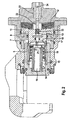
- the second embodiment of the vehicle brake according to the invention differs from the embodiment described with reference to FIG. 1 substantially by the use of an electromechanical actuator 33 instead of the electromagnetic actuator 3 for locking the power transmission element. 2
- the electromechanical actuator 33 drives a drive shaft 34 which is connected to the rotor, not shown, of the electromechanical actuator 33.
- the drive shaft 34 in turn is connected to the power transmission element 2 and drives it.
- the connection between the drive shaft 34 and the power transmission element 2 is formed as an adaptive connection 32, so that a relative movement between the above-mentioned components is possible.
- the power transmission element 2 is connected via a self-locking thread 35 with the accumulator piston 11 and forms as in the first embodiment described above, the function of a central bearing 21 for the spindle 16.
- the power transmission element 2 is rotated by the electromechanical actuator 33 in the drawing to the right formed on the spindle 16, the first friction surface 17 and the memory piston rotatably formed, second friction surface 18 are engaged with each other.
- the locking of the embodiment shown in Fig. 2 also takes place after a pressure buildup in the operating pressure chamber 7 and the accumulator pressure chamber 9, after which on the one hand the brake piston 6 is moved in the drawing to the left in the direction of the brake disc, not shown, and the accumulator piston 11 is moved in the drawing to the right becomes. Due to the connection between the accumulator piston 11 and the power transmission element 2 in the form of the above-described self-locking thread 35, the power transmission element 2 is taken from the accumulator piston 11 and moved in the drawing to the right. In this process, the drive shaft 34 and the power transmission element 2 perform a relative movement to the already described connection 32 of the two components.
- the spindle 16 continues in this process by the already described force of the spring 19 on the force transmission element 2 and the friction surfaces 17, 18 are not engaged with each other.
- the two friction surfaces 17, 18 are first brought into engagement with each other after the electromechanical actuator 33 is driven accordingly and moves the power transmission element 2 by the rotational movement of the drive shaft 34 in the drawing to the right. Subsequently, the spindle 16 is blocked and the pressure in the chambers 7, 9 controlled pressure is reduced.
- the already described spring assembly 12 now acts on the accumulator piston 11, the mutually engaging friction surfaces 17, 18, the threaded nut spindle assembly 14 on the brake piston 6, which is thus locked in the clamped state.
- the electromechanical actuator 33 also performs the function of a sensor for detecting the position of the power transmission element 2. Use this information to determine if the vehicle brake is locked or released. For this purpose, the power requirement of the electromechanical actuator 33 is determined, which suggests the position of the drive shaft 34 and thus the position of the power transmission element 2. Alternatively, a so-called step count sensor can be used, which determines the number of revolutions of the electromechanical actuator 2. With the help of this information, in turn, the position of the force transmission element 2 can be determined.
- the separate storage pressure chamber 9 is dispensed with.
- a brake piston and a storage piston are actuated in this embodiment by a pressure applied in a common pressure chamber.
- a storage piston movement is prevented by the spring element 12 described with reference to FIGS. 1 and 2.
- the force transmission element is actuated correspondingly by an electromechanical actuator, so that two friction surfaces, which are formed on the accumulator piston and on the threaded spindle of a cooperating with the brake piston threaded spindle arrangement, can engage with each other.
- To release the parking brake actuates the electromechanical actuator the force transmission element, after which the aforementioned friction surfaces are disengaged.
- a hydraulic pump can be used, which serves as an external pressure source of an electro-hydraulic brake system. It is also conceivable an operating unit with a externally controllable brake booster and a brake booster downstream master cylinder. Alternatively, however, can also be used by the driver operable pressure generator.
Landscapes
- Engineering & Computer Science (AREA)
- General Engineering & Computer Science (AREA)
- Mechanical Engineering (AREA)
- Braking Arrangements (AREA)
- Braking Systems And Boosters (AREA)
Applications Claiming Priority (4)
| Application Number | Priority Date | Filing Date | Title |
|---|---|---|---|
| DE102004006436 | 2004-02-09 | ||
| DE102004049656 | 2004-10-11 | ||
| DE102004062810A DE102004062810A1 (de) | 2004-02-09 | 2004-12-27 | Hydraulische Fahrzeugbremse |
| PCT/EP2005/050574 WO2005075848A1 (de) | 2004-02-09 | 2005-02-09 | Hydraulische fahrzeugbremse |
Publications (2)
| Publication Number | Publication Date |
|---|---|
| EP1714048A1 EP1714048A1 (de) | 2006-10-25 |
| EP1714048B1 true EP1714048B1 (de) | 2008-01-09 |
Family
ID=34841372
Family Applications (1)
| Application Number | Title | Priority Date | Filing Date |
|---|---|---|---|
| EP05707986A Active EP1714048B1 (de) | 2004-02-09 | 2005-02-09 | Hydraulische fahrzeugbremse |
Country Status (6)
| Country | Link |
|---|---|
| US (1) | US20070132309A1 (ja) |
| EP (1) | EP1714048B1 (ja) |
| JP (1) | JP2007522398A (ja) |
| KR (1) | KR20060135743A (ja) |
| DE (1) | DE502005002498D1 (ja) |
| WO (1) | WO2005075848A1 (ja) |
Families Citing this family (9)
| Publication number | Priority date | Publication date | Assignee | Title |
|---|---|---|---|---|
| DE102005059937A1 (de) * | 2004-12-21 | 2006-07-13 | Continental Teves Ag & Co. Ohg | Verfahren zum Betrieb einer hydraulischen Bremsanlage für Kraftfahrzeuge |
| JP4674690B2 (ja) * | 2005-09-30 | 2011-04-20 | 日立オートモティブシステムズ株式会社 | ディスクブレーキ |
| JP4521615B2 (ja) * | 2005-09-30 | 2010-08-11 | 日立オートモティブシステムズ株式会社 | ディスクブレーキ |
| DE102007022510A1 (de) * | 2007-05-14 | 2008-11-20 | Robert Bosch Gmbh | Automatische Feststellbremse mit Schlupfregler |
| US8205446B2 (en) | 2008-11-07 | 2012-06-26 | Xingyun Xie | Driving unit for brake |
| KR101325857B1 (ko) * | 2011-12-07 | 2013-11-05 | 조인효 | 유압 작동식 브레이크 장치 |
| KR20140134016A (ko) * | 2013-05-13 | 2014-11-21 | 현대모비스 주식회사 | 통합형 제동시스템 |
| CN104565142B (zh) * | 2015-01-28 | 2018-09-25 | 安徽昕宏通用设备制造有限公司 | 一种制动器自锁装置 |
| US20230406281A1 (en) * | 2022-06-21 | 2023-12-21 | Oshkosh Corporation | Brake system |
Family Cites Families (12)
| Publication number | Priority date | Publication date | Assignee | Title |
|---|---|---|---|---|
| GB1496154A (en) * | 1974-05-08 | 1977-12-30 | Girling Ltd | Vehicle disc brakes |
| US4014414A (en) * | 1975-07-07 | 1977-03-29 | Yamamoto Mayjue A | Power parking failsafe disc brake |
| DE2809263C2 (de) * | 1978-03-03 | 1982-04-29 | Knorr-Bremse GmbH, 8000 München | Mechanische Lösevorrichtung für Federspeicherbremszylinder |
| US4361078A (en) * | 1981-03-16 | 1982-11-30 | Wabco Ltd. | Hydraulic brake actuator having spring-applied back-up brake with manual release means |
| DE19511811B4 (de) * | 1995-03-30 | 2005-10-06 | Lucas Industries P.L.C., Solihull | Elektronisch steuerbare Bremsanlage für Landfahrzeuge und Verfahren zu deren Betrieb |
| JP2000504811A (ja) * | 1996-02-09 | 2000-04-18 | アイティーティー・マニュファクチュリング・エンタープライゼス・インコーポレイテッド | 組み合せ式常用兼駐車ブレーキ装置 |
| US6311808B1 (en) * | 1996-02-09 | 2001-11-06 | Continental Teves Ag & Co., Ohg | Combined service and parking brake system |
| DE19621533A1 (de) * | 1996-05-29 | 1997-12-04 | Bosch Gmbh Robert | Elektromotorische Bremsvorrichtung |
| DE19732168C2 (de) * | 1997-07-25 | 2003-06-18 | Lucas Ind Plc | Hydraulische Fahrzeugbremse mit Feststelleinrichtung und Verfahren zum Betreiben derselben |
| DE10320800A1 (de) * | 2002-07-03 | 2004-01-22 | Continental Teves Ag & Co. Ohg | Hydraulische Fahrzeugbremse |
| ES2258729T3 (es) * | 2002-09-17 | 2006-09-01 | CONTINENTAL TEVES AG & CO. OHG | Freno hidraulico para vehiculos. |
| WO2004089713A1 (de) * | 2003-04-08 | 2004-10-21 | Continental Teves Ag & Co. Ohg | Verfahren zum betrieb eines hydraulischen bremssystems mit integrierter feststellbremsfunktion für kraftfahrzeuge |
-
2005
- 2005-02-09 KR KR1020067015925A patent/KR20060135743A/ko not_active Application Discontinuation
- 2005-02-09 EP EP05707986A patent/EP1714048B1/de active Active
- 2005-02-09 JP JP2006551862A patent/JP2007522398A/ja active Pending
- 2005-02-09 US US10/588,829 patent/US20070132309A1/en not_active Abandoned
- 2005-02-09 WO PCT/EP2005/050574 patent/WO2005075848A1/de active IP Right Grant
- 2005-02-09 DE DE502005002498T patent/DE502005002498D1/de not_active Withdrawn - After Issue
Also Published As
| Publication number | Publication date |
|---|---|
| KR20060135743A (ko) | 2006-12-29 |
| EP1714048A1 (de) | 2006-10-25 |
| US20070132309A1 (en) | 2007-06-14 |
| DE502005002498D1 (de) | 2008-02-21 |
| JP2007522398A (ja) | 2007-08-09 |
| WO2005075848A1 (de) | 2005-08-18 |
Similar Documents
| Publication | Publication Date | Title |
|---|---|---|
| EP1554504B1 (de) | Hydraulische fahrzeugbremse | |
| EP1714048B1 (de) | Hydraulische fahrzeugbremse | |
| EP2069655B1 (de) | Kombinierte fahrzeugbremse mit elektromechanisch betätigbarer feststellbremse und getriebe zur umsetzung einer rotationsbewegung in eine translationsbewegung | |
| DE102004004992B4 (de) | Verfahren zum Betreiben der Bremsausrüstung eines Fahrzeugs | |
| DE10035220B4 (de) | Verfahren zum Betrieb einer Radbremsvorrichtung | |
| EP0877693B1 (de) | Kombinierte betriebs- und feststellbremsanlage | |
| DE602005003162T2 (de) | Feststellbremse | |
| EP2785568B1 (de) | Federspeicherbremszylinder mit notlöseeinrichtung | |
| WO2013189655A1 (de) | Vorrichtung zum betätigen eines verriegelungsmechanismus | |
| WO2007036357A1 (de) | Fahrzeugbremse, insbesondere sattelbremse | |
| EP1759131A1 (de) | Aktuatorvorrichtung zum betätigen eines verriegelungsmechanismus | |
| EP2651730B1 (de) | Elektromechanisch betätigbare bremse und verfahren zum betreiben einer elektromechanisch betätigbaren bremse | |
| DE102006001546A1 (de) | Hydraulische Fahrzeugbremse mit Feststellbremsvorrichtung | |
| EP1716351B1 (de) | Hydraulische fahrzeugbremse mit feststellbremsvorrichtung und verfahren zu deren betrieb | |
| WO2002044002A1 (de) | Bremsaktuator | |
| WO2004099644A1 (de) | Fahrzeugbremse und verfahren zum betätigen einer fahrzeugbremse | |
| WO2004089713A1 (de) | Verfahren zum betrieb eines hydraulischen bremssystems mit integrierter feststellbremsfunktion für kraftfahrzeuge | |
| DE102011086152A1 (de) | Bremseinrichtung | |
| DE102004015447A1 (de) | Vorrichtung und Verfahren zum Notbetrieb eines hydraulischen Bremssystems für Kraftfahrzeuge | |
| DE10329694A1 (de) | Hydraulische Fahrzeugbremse | |
| DE102004062810A1 (de) | Hydraulische Fahrzeugbremse | |
| DE102006001543A1 (de) | Hydraulische Fahrzeugbremse mit Feststellbremsvorrichtung | |
| DE102004043309A1 (de) | Hydraulische Fahrzeugbremse | |
| DE102005023362B4 (de) | Fahrzeugbremse mit integrierter Feststelleinrichtung sowie Verfahren zum Betreiben einer Feststelleinrichtung | |
| DE102005012009A1 (de) | Feststellbremsvorrichtung |
Legal Events
| Date | Code | Title | Description |
|---|---|---|---|
| PUAI | Public reference made under article 153(3) epc to a published international application that has entered the european phase |
Free format text: ORIGINAL CODE: 0009012 |
|
| 17P | Request for examination filed |
Effective date: 20060808 |
|
| AK | Designated contracting states |
Kind code of ref document: A1 Designated state(s): DE FR IT |
|
| RIN1 | Information on inventor provided before grant (corrected) |
Inventor name: PEICHL, THOMAS Inventor name: BALZ, JUERGEN Inventor name: VOELKEL, JUERGEN Inventor name: KNOP, VOLKER Inventor name: SCHIEL, LOTHAR Inventor name: WINKLER, THOMAS |
|
| DAX | Request for extension of the european patent (deleted) | ||
| RBV | Designated contracting states (corrected) |
Designated state(s): DE FR IT |
|
| GRAP | Despatch of communication of intention to grant a patent |
Free format text: ORIGINAL CODE: EPIDOSNIGR1 |
|
| GRAS | Grant fee paid |
Free format text: ORIGINAL CODE: EPIDOSNIGR3 |
|
| GRAA | (expected) grant |
Free format text: ORIGINAL CODE: 0009210 |
|
| AK | Designated contracting states |
Kind code of ref document: B1 Designated state(s): DE FR IT |
|
| REF | Corresponds to: |
Ref document number: 502005002498 Country of ref document: DE Date of ref document: 20080221 Kind code of ref document: P |
|
| ET | Fr: translation filed | ||
| PLBE | No opposition filed within time limit |
Free format text: ORIGINAL CODE: 0009261 |
|
| STAA | Information on the status of an ep patent application or granted ep patent |
Free format text: STATUS: NO OPPOSITION FILED WITHIN TIME LIMIT |
|
| 26N | No opposition filed |
Effective date: 20081010 |
|
| PGFP | Annual fee paid to national office [announced via postgrant information from national office to epo] |
Ref country code: FR Payment date: 20100225 Year of fee payment: 6 |
|
| PGFP | Annual fee paid to national office [announced via postgrant information from national office to epo] |
Ref country code: DE Payment date: 20100228 Year of fee payment: 6 |
|
| PG25 | Lapsed in a contracting state [announced via postgrant information from national office to epo] |
Ref country code: DE Free format text: LAPSE BECAUSE OF THE APPLICANT RENOUNCES Effective date: 20100701 |
|
| REG | Reference to a national code |
Ref country code: FR Ref legal event code: ST Effective date: 20111102 |
|
| PGFP | Annual fee paid to national office [announced via postgrant information from national office to epo] |
Ref country code: IT Payment date: 20080228 Year of fee payment: 4 |
|
| PG25 | Lapsed in a contracting state [announced via postgrant information from national office to epo] |
Ref country code: FR Free format text: LAPSE BECAUSE OF NON-PAYMENT OF DUE FEES Effective date: 20110228 |