EP1707831A1 - Thrust needle roller bearing, support structure receiving thrust load of compressor for car air-conditioner, support structure receiving thrust load of automatic transmission, support structure for nonstep variable speed gear, and support structure receiving thrust load of manual transmission - Google Patents
Thrust needle roller bearing, support structure receiving thrust load of compressor for car air-conditioner, support structure receiving thrust load of automatic transmission, support structure for nonstep variable speed gear, and support structure receiving thrust load of manual transmission Download PDFInfo
- Publication number
- EP1707831A1 EP1707831A1 EP04807374A EP04807374A EP1707831A1 EP 1707831 A1 EP1707831 A1 EP 1707831A1 EP 04807374 A EP04807374 A EP 04807374A EP 04807374 A EP04807374 A EP 04807374A EP 1707831 A1 EP1707831 A1 EP 1707831A1
- Authority
- EP
- European Patent Office
- Prior art keywords
- support structure
- surface layer
- layer portion
- needle roller
- washer
- Prior art date
- Legal status (The legal status is an assumption and is not a legal conclusion. Google has not performed a legal analysis and makes no representation as to the accuracy of the status listed.)
- Granted
Links
- 230000005540 biological transmission Effects 0.000 title claims description 70
- IJGRMHOSHXDMSA-UHFFFAOYSA-N Atomic nitrogen Chemical compound N#N IJGRMHOSHXDMSA-UHFFFAOYSA-N 0.000 claims abstract description 96
- 229910001566 austenite Inorganic materials 0.000 claims abstract description 76
- 239000002344 surface layer Substances 0.000 claims abstract description 71
- 229910052757 nitrogen Inorganic materials 0.000 claims abstract description 48
- 229910000831 Steel Inorganic materials 0.000 claims abstract description 46
- 239000010959 steel Substances 0.000 claims abstract description 46
- 239000010410 layer Substances 0.000 claims abstract description 28
- 230000000717 retained effect Effects 0.000 claims abstract description 26
- 230000008859 change Effects 0.000 claims description 2
- 238000005096 rolling process Methods 0.000 abstract description 14
- 230000001419 dependent effect Effects 0.000 abstract description 12
- 238000005256 carbonitriding Methods 0.000 description 57
- 238000000034 method Methods 0.000 description 55
- 238000010438 heat treatment Methods 0.000 description 52
- 238000010791 quenching Methods 0.000 description 42
- 230000000171 quenching effect Effects 0.000 description 42
- 230000008569 process Effects 0.000 description 40
- 239000000463 material Substances 0.000 description 19
- OKTJSMMVPCPJKN-UHFFFAOYSA-N Carbon Chemical compound [C] OKTJSMMVPCPJKN-UHFFFAOYSA-N 0.000 description 18
- 229910052799 carbon Inorganic materials 0.000 description 18
- 230000009466 transformation Effects 0.000 description 14
- 230000007246 mechanism Effects 0.000 description 13
- 239000013078 crystal Substances 0.000 description 12
- 239000003921 oil Substances 0.000 description 11
- 102220573299 Coiled-coil domain-containing protein 92_S70C_mutation Human genes 0.000 description 9
- 238000012360 testing method Methods 0.000 description 9
- 230000007423 decrease Effects 0.000 description 7
- 230000008878 coupling Effects 0.000 description 6
- 238000010168 coupling process Methods 0.000 description 6
- 238000005859 coupling reaction Methods 0.000 description 6
- 150000004767 nitrides Chemical class 0.000 description 6
- 238000012545 processing Methods 0.000 description 6
- 238000005255 carburizing Methods 0.000 description 5
- XEEYBQQBJWHFJM-UHFFFAOYSA-N Iron Chemical compound [Fe] XEEYBQQBJWHFJM-UHFFFAOYSA-N 0.000 description 4
- 238000005461 lubrication Methods 0.000 description 4
- 229910000734 martensite Inorganic materials 0.000 description 4
- 239000000523 sample Substances 0.000 description 4
- 238000005496 tempering Methods 0.000 description 4
- 229910000954 Medium-carbon steel Inorganic materials 0.000 description 3
- 239000000654 additive Substances 0.000 description 3
- 230000000996 additive effect Effects 0.000 description 3
- 238000001816 cooling Methods 0.000 description 3
- 238000004453 electron probe microanalysis Methods 0.000 description 3
- 230000035882 stress Effects 0.000 description 3
- 238000011282 treatment Methods 0.000 description 3
- 229910000746 Structural steel Inorganic materials 0.000 description 2
- 238000002441 X-ray diffraction Methods 0.000 description 2
- 229910001567 cementite Inorganic materials 0.000 description 2
- 239000011651 chromium Substances 0.000 description 2
- 239000010960 cold rolled steel Substances 0.000 description 2
- 230000000052 comparative effect Effects 0.000 description 2
- 230000000694 effects Effects 0.000 description 2
- 230000006870 function Effects 0.000 description 2
- 239000007789 gas Substances 0.000 description 2
- 230000006872 improvement Effects 0.000 description 2
- 230000006698 induction Effects 0.000 description 2
- 229910052742 iron Inorganic materials 0.000 description 2
- KSOKAHYVTMZFBJ-UHFFFAOYSA-N iron;methane Chemical compound C.[Fe].[Fe].[Fe] KSOKAHYVTMZFBJ-UHFFFAOYSA-N 0.000 description 2
- 239000007788 liquid Substances 0.000 description 2
- 230000005291 magnetic effect Effects 0.000 description 2
- 239000011572 manganese Substances 0.000 description 2
- QMQXDJATSGGYDR-UHFFFAOYSA-N methylidyneiron Chemical compound [C].[Fe] QMQXDJATSGGYDR-UHFFFAOYSA-N 0.000 description 2
- 230000004048 modification Effects 0.000 description 2
- 238000012986 modification Methods 0.000 description 2
- 238000010587 phase diagram Methods 0.000 description 2
- 239000006104 solid solution Substances 0.000 description 2
- 238000005482 strain hardening Methods 0.000 description 2
- 229910000859 α-Fe Inorganic materials 0.000 description 2
- QGZKDVFQNNGYKY-UHFFFAOYSA-N Ammonia Chemical compound N QGZKDVFQNNGYKY-UHFFFAOYSA-N 0.000 description 1
- 229910000975 Carbon steel Inorganic materials 0.000 description 1
- VYZAMTAEIAYCRO-UHFFFAOYSA-N Chromium Chemical compound [Cr] VYZAMTAEIAYCRO-UHFFFAOYSA-N 0.000 description 1
- PWHULOQIROXLJO-UHFFFAOYSA-N Manganese Chemical compound [Mn] PWHULOQIROXLJO-UHFFFAOYSA-N 0.000 description 1
- 230000032683 aging Effects 0.000 description 1
- 229910045601 alloy Inorganic materials 0.000 description 1
- 239000000956 alloy Substances 0.000 description 1
- 238000004458 analytical method Methods 0.000 description 1
- 239000010962 carbon steel Substances 0.000 description 1
- 229910052804 chromium Inorganic materials 0.000 description 1
- VNTLIPZTSJSULJ-UHFFFAOYSA-N chromium molybdenum Chemical compound [Cr].[Mo] VNTLIPZTSJSULJ-UHFFFAOYSA-N 0.000 description 1
- 238000012937 correction Methods 0.000 description 1
- 238000002788 crimping Methods 0.000 description 1
- 238000005520 cutting process Methods 0.000 description 1
- 238000011161 development Methods 0.000 description 1
- 230000018109 developmental process Effects 0.000 description 1
- 238000005530 etching Methods 0.000 description 1
- 230000005294 ferromagnetic effect Effects 0.000 description 1
- 238000000227 grinding Methods 0.000 description 1
- 230000020169 heat generation Effects 0.000 description 1
- 239000000314 lubricant Substances 0.000 description 1
- 229910052748 manganese Inorganic materials 0.000 description 1
- 238000004519 manufacturing process Methods 0.000 description 1
- 238000005259 measurement Methods 0.000 description 1
- 229910052751 metal Inorganic materials 0.000 description 1
- 239000002184 metal Substances 0.000 description 1
- FXNGWBDIVIGISM-UHFFFAOYSA-N methylidynechromium Chemical group [Cr]#[C] FXNGWBDIVIGISM-UHFFFAOYSA-N 0.000 description 1
- 238000010899 nucleation Methods 0.000 description 1
- 230000006911 nucleation Effects 0.000 description 1
- 239000011148 porous material Substances 0.000 description 1
- 238000003825 pressing Methods 0.000 description 1
- 238000010992 reflux Methods 0.000 description 1
- 238000005480 shot peening Methods 0.000 description 1
- 229910052710 silicon Inorganic materials 0.000 description 1
- 239000010703 silicon Substances 0.000 description 1
- 238000010792 warming Methods 0.000 description 1
- 238000004804 winding Methods 0.000 description 1
Images





Classifications
-
- F—MECHANICAL ENGINEERING; LIGHTING; HEATING; WEAPONS; BLASTING
- F04—POSITIVE - DISPLACEMENT MACHINES FOR LIQUIDS; PUMPS FOR LIQUIDS OR ELASTIC FLUIDS
- F04B—POSITIVE-DISPLACEMENT MACHINES FOR LIQUIDS; PUMPS
- F04B27/00—Multi-cylinder pumps specially adapted for elastic fluids and characterised by number or arrangement of cylinders
- F04B27/08—Multi-cylinder pumps specially adapted for elastic fluids and characterised by number or arrangement of cylinders having cylinders coaxial with, or parallel or inclined to, main shaft axis
- F04B27/10—Multi-cylinder pumps specially adapted for elastic fluids and characterised by number or arrangement of cylinders having cylinders coaxial with, or parallel or inclined to, main shaft axis having stationary cylinders
- F04B27/1036—Component parts, details, e.g. sealings, lubrication
- F04B27/1054—Actuating elements
- F04B27/1063—Actuating-element bearing means or driving-axis bearing means
-
- F—MECHANICAL ENGINEERING; LIGHTING; HEATING; WEAPONS; BLASTING
- F16—ENGINEERING ELEMENTS AND UNITS; GENERAL MEASURES FOR PRODUCING AND MAINTAINING EFFECTIVE FUNCTIONING OF MACHINES OR INSTALLATIONS; THERMAL INSULATION IN GENERAL
- F16C—SHAFTS; FLEXIBLE SHAFTS; ELEMENTS OR CRANKSHAFT MECHANISMS; ROTARY BODIES OTHER THAN GEARING ELEMENTS; BEARINGS
- F16C19/00—Bearings with rolling contact, for exclusively rotary movement
- F16C19/22—Bearings with rolling contact, for exclusively rotary movement with bearing rollers essentially of the same size in one or more circular rows, e.g. needle bearings
- F16C19/30—Bearings with rolling contact, for exclusively rotary movement with bearing rollers essentially of the same size in one or more circular rows, e.g. needle bearings for axial load mainly
-
- F—MECHANICAL ENGINEERING; LIGHTING; HEATING; WEAPONS; BLASTING
- F16—ENGINEERING ELEMENTS AND UNITS; GENERAL MEASURES FOR PRODUCING AND MAINTAINING EFFECTIVE FUNCTIONING OF MACHINES OR INSTALLATIONS; THERMAL INSULATION IN GENERAL
- F16C—SHAFTS; FLEXIBLE SHAFTS; ELEMENTS OR CRANKSHAFT MECHANISMS; ROTARY BODIES OTHER THAN GEARING ELEMENTS; BEARINGS
- F16C33/00—Parts of bearings; Special methods for making bearings or parts thereof
- F16C33/30—Parts of ball or roller bearings
- F16C33/34—Rollers; Needles
-
- F—MECHANICAL ENGINEERING; LIGHTING; HEATING; WEAPONS; BLASTING
- F16—ENGINEERING ELEMENTS AND UNITS; GENERAL MEASURES FOR PRODUCING AND MAINTAINING EFFECTIVE FUNCTIONING OF MACHINES OR INSTALLATIONS; THERMAL INSULATION IN GENERAL
- F16C—SHAFTS; FLEXIBLE SHAFTS; ELEMENTS OR CRANKSHAFT MECHANISMS; ROTARY BODIES OTHER THAN GEARING ELEMENTS; BEARINGS
- F16C33/00—Parts of bearings; Special methods for making bearings or parts thereof
- F16C33/30—Parts of ball or roller bearings
- F16C33/58—Raceways; Race rings
- F16C33/62—Selection of substances
-
- F—MECHANICAL ENGINEERING; LIGHTING; HEATING; WEAPONS; BLASTING
- F16—ENGINEERING ELEMENTS AND UNITS; GENERAL MEASURES FOR PRODUCING AND MAINTAINING EFFECTIVE FUNCTIONING OF MACHINES OR INSTALLATIONS; THERMAL INSULATION IN GENERAL
- F16C—SHAFTS; FLEXIBLE SHAFTS; ELEMENTS OR CRANKSHAFT MECHANISMS; ROTARY BODIES OTHER THAN GEARING ELEMENTS; BEARINGS
- F16C33/00—Parts of bearings; Special methods for making bearings or parts thereof
- F16C33/30—Parts of ball or roller bearings
- F16C33/58—Raceways; Race rings
- F16C33/64—Special methods of manufacture
-
- F—MECHANICAL ENGINEERING; LIGHTING; HEATING; WEAPONS; BLASTING
- F16—ENGINEERING ELEMENTS AND UNITS; GENERAL MEASURES FOR PRODUCING AND MAINTAINING EFFECTIVE FUNCTIONING OF MACHINES OR INSTALLATIONS; THERMAL INSULATION IN GENERAL
- F16H—GEARING
- F16H41/00—Rotary fluid gearing of the hydrokinetic type
- F16H41/24—Details
-
- F—MECHANICAL ENGINEERING; LIGHTING; HEATING; WEAPONS; BLASTING
- F16—ENGINEERING ELEMENTS AND UNITS; GENERAL MEASURES FOR PRODUCING AND MAINTAINING EFFECTIVE FUNCTIONING OF MACHINES OR INSTALLATIONS; THERMAL INSULATION IN GENERAL
- F16C—SHAFTS; FLEXIBLE SHAFTS; ELEMENTS OR CRANKSHAFT MECHANISMS; ROTARY BODIES OTHER THAN GEARING ELEMENTS; BEARINGS
- F16C19/00—Bearings with rolling contact, for exclusively rotary movement
- F16C19/22—Bearings with rolling contact, for exclusively rotary movement with bearing rollers essentially of the same size in one or more circular rows, e.g. needle bearings
- F16C19/44—Needle bearings
- F16C19/46—Needle bearings with one row or needles
-
- F—MECHANICAL ENGINEERING; LIGHTING; HEATING; WEAPONS; BLASTING
- F16—ENGINEERING ELEMENTS AND UNITS; GENERAL MEASURES FOR PRODUCING AND MAINTAINING EFFECTIVE FUNCTIONING OF MACHINES OR INSTALLATIONS; THERMAL INSULATION IN GENERAL
- F16C—SHAFTS; FLEXIBLE SHAFTS; ELEMENTS OR CRANKSHAFT MECHANISMS; ROTARY BODIES OTHER THAN GEARING ELEMENTS; BEARINGS
- F16C2360/00—Engines or pumps
-
- F—MECHANICAL ENGINEERING; LIGHTING; HEATING; WEAPONS; BLASTING
- F16—ENGINEERING ELEMENTS AND UNITS; GENERAL MEASURES FOR PRODUCING AND MAINTAINING EFFECTIVE FUNCTIONING OF MACHINES OR INSTALLATIONS; THERMAL INSULATION IN GENERAL
- F16C—SHAFTS; FLEXIBLE SHAFTS; ELEMENTS OR CRANKSHAFT MECHANISMS; ROTARY BODIES OTHER THAN GEARING ELEMENTS; BEARINGS
- F16C2361/00—Apparatus or articles in engineering in general
- F16C2361/63—Gears with belts and pulleys
-
- F—MECHANICAL ENGINEERING; LIGHTING; HEATING; WEAPONS; BLASTING
- F16—ENGINEERING ELEMENTS AND UNITS; GENERAL MEASURES FOR PRODUCING AND MAINTAINING EFFECTIVE FUNCTIONING OF MACHINES OR INSTALLATIONS; THERMAL INSULATION IN GENERAL
- F16C—SHAFTS; FLEXIBLE SHAFTS; ELEMENTS OR CRANKSHAFT MECHANISMS; ROTARY BODIES OTHER THAN GEARING ELEMENTS; BEARINGS
- F16C2361/00—Apparatus or articles in engineering in general
- F16C2361/65—Gear shifting, change speed gear, gear box
-
- F—MECHANICAL ENGINEERING; LIGHTING; HEATING; WEAPONS; BLASTING
- F16—ENGINEERING ELEMENTS AND UNITS; GENERAL MEASURES FOR PRODUCING AND MAINTAINING EFFECTIVE FUNCTIONING OF MACHINES OR INSTALLATIONS; THERMAL INSULATION IN GENERAL
- F16H—GEARING
- F16H57/00—General details of gearing
- F16H57/02—Gearboxes; Mounting gearing therein
- F16H57/021—Shaft support structures, e.g. partition walls, bearing eyes, casing walls or covers with bearings
Definitions
- the present invention relates to a thrust needle roller bearing, a support structure receiving thrust load of a compressor for car air-conditioner, a support structure receiving thrust load of an automatic transmission, a support structure for a continuously variable transmission and a support structure receiving thrust load of a manual transmission.
- a thrust needle roller bearing consists of needle rollers, a cage and a washer, in which the needle rollers are in line-contact with the washer. Therefore, the bearing advantageously attains high load carrying capacity and high rigidity, for its small projection area. Therefore, a thrust needle roller bearing is used in a support structure of a compressor for car air-conditioner and a support structure of a transmission (manual transmission, automatic transmission and continuously variable transmission).
- Such a thrust needle roller bearing is disclosed, for example, in Patent Document 1 ( Japanese Patent Laying-Open No. 2002-70872 ).
- Oil used in a compressor for a car air-conditioner has low viscosity, and the amount of oil is made small in order to improve compressor performance (cooling performance).
- the bearing might possibly fail at an early stage because of surface damage, such as surface-originated flaking, if there is much differential slip at the roller.
- Patent Document 1 Japanese Patent Laying-Open No. 2002-70872
- heat caused by differential slip at the roller may induce damage such as surface-originated flaking. Enforcement of the washer against the surface damage including the surface-originated flaking is desired.
- the present invention was made in view of the foregoing and an object is to provide a long life thrust needle roller bearing having at least washer characteristic changed to be resistant to an early failure caused by surface damage such as surface-originated flaking and resistant also to common load-dependent rolling contact fatigue.
- the present invention was made in view of the foregoing and another object is to provide a long life support structure receiving thrust load of a compressor for car air-conditioner, having at least washer characteristic changed to be resistant to an early failure caused by surface damage such as surface-originated flaking and resistant also to common load-dependent rolling contact fatigue.
- the present invention was made in view of the foregoing and a further object is to provide a long life support structure receiving thrust load of an automatic transmission, of which thrust needle roller bearing is resistant to an early failure caused by surface damage such as surface-originated flaking and resistant also to common load-dependent rolling contact fatigue.
- the present invention was made in view of the foregoing and a still further object is to provide a long life support structure for a continuously variable transmission, of which thrust needle roller bearing is resistant to an early failure caused by surface damage such as surface-originated flaking and resistant also to common load-dependent rolling contact fatigue.
- the present invention was made in view of the foregoing and a still further object is to provide a long life support structure receiving thrust load of a manual transmission, of which thrust needle roller bearing is resistant to an early failure caused by surface damage such as surface-originated flaking and resistant also to common load-dependent rolling contact fatigue.
- the present invention provides a thrust needle roller bearing having a washer formed of a thin steel plate and needle rollers, wherein at least the washer has a nitrogen enriched layer at a surface layer portion, amount of retained austenite in the surface layer portion is at least 5 volume % and at most 25 volume %, and austenite grain size number of the surface layer portion is 11 or higher.
- nitrogen content of the surface layer portion is in the range of 0.1 mass % to 0.7 mass %.
- the support structure receiving thrust load of a compressor for a car air-conditioner in accordance with the present invention is a support structure receiving thrust load of a compressor for a car air-conditioner in which a swash plate rotates as a main shaft rotates and a piston swings accordingly, including a thrust needle roller bearing receiving thrust load generated by the rotation of the swash plate, having a washer formed of a thin steel plate and needle rollers, wherein at least the washer has a nitrogen enriched layer at a surface layer portion, amount of retained austenite in the surface layer portion is at least 5 volume % and at most 25 volume %, and austenite grain size number of the surface layer portion is 11 or higher.
- nitrogen content of the surface layer portion is in the range of 0.1 mass % to 0.7 mass %.
- the support structure receiving thrust load of an automatic transmission in accordance with the present invention is a support structure receiving thrust load of an automatic transmission including a torque converter having an impeller and a turbine opposite to each other with a stator in between, including a thrust needle roller bearing having a washer formed of a thin steel plate and needle rollers, at least between the stator and the impeller or between the stator and the turbine. At least the washer has a nitrogen enriched layer at a surface layer portion, amount of retained austenite in the surface layer portion is at least 5 volume % and at most 25 volume %, and austenite grain size number of the surface layer portion is 11 or higher.
- nitrogen content of the surface layer portion is in the range of 0.1 mass % to 0.7 mass %.
- the support structure for a continuously variable transmission in accordance with the present invention is a support structure for a continuously variable transmission in which rotation of an input shaft is changed in a nonstep manner and transmitted to an output shaft.
- a thrust needle roller bearing receiving thrust load generated by the rotation either of the input shaft or the output shaft has a washer formed of a thin steel plate and needle rollers, at least the washer has a nitrogen enriched layer at a surface layer portion, amount of retained austenite in the surface layer portion is at least 5 volume % and at most 25 volume %, and austenite grain size number of the surface layer portion is 11 or higher.
- nitrogen content of the surface layer portion of the thrust needle roller bearing is in the range of 0.1 mass % to 0.7 mass %.
- the support structure receiving thrust load of a manual transmission in accordance with the present invention is a support structure receiving thrust load of a manual transmission allowing, by engagement between a gear of an input shaft and a gear of a counter shaft and engagement between a gear of the counter shaft and a gear of an output shaft, stepwise change of speed of rotation of the output shaft from the speed of rotation of the input shaft, including a thrust needle roller bearing receiving thrust load of any of the input shaft, the counter shaft and the output shaft, having a washer formed of a thin steel plate and needle rollers, wherein at least the washer has a nitrogen enriched layer at a surface layer portion, amount of retained austenite in the surface layer portion is at least 5 volume % and at most 25 volume %, and austenite grain size number of the surface layer portion is 11 or higher.
- nitrogen content of the surface layer portion of the thrust needle roller bearing is in the range of 0.1 mass % to 0.7 mass %.
- the washer material is adapted to have fine crystal grain size and high heat resistance, and therefore, life defined by surface-originated flaking (surface damage such as peeling and smearing) and life defined by subsurface-originated flaking can both be improved.
- the washer material is adapted to have fine crystal grain size and high heat resistance, and therefore, life defined by surface-originated flaking (surface damage such as peeling and smearing) and life defined by subsurface-originated flaking can both be improved.
- the washer material of the thrust needle roller bearing is adapted to have fine crystal grain size and high heat resistance, and therefore, life defined by surface-originated flaking (surface damage such as peeling and smearing) and life defined by subsurface-originated flaking can both be improved.
- the washer material of the thrust needle roller bearing is adapted to have fine crystal grain size and high heat resistance, and therefore, life defined by surface-originated flaking (surface damage such as peeling and smearing) and life defined by subsurface-originated flaking can both be improved.
- the washer material of the thrust needle roller bearing is adapted to have fine crystal grain size and high heat resistance, and therefore, life defined by surface-originated flaking (surface damage such as peeling and smearing) and life defined by subsurface-originated flaking can both be improved.
- a carbonitrided texture (nitrogen enriched layer) reliably having autstenite grain size number of 11 or higher can be obtained.
- This texture significantly increases resistance to generation and development of cracks.
- heat generation at a surface layer caused by slipping or surface cracks caused by tangential force can be suppressed.
- the inventors have found that significantly longer life can be attained as regards cracks caused by subsurface-originated flaking.
- a heat-resistant, nitrogen enriched layer having fine carbide deposited at the surface layer portion is formed.
- a nitrogen enriched layer is formed, and in addition, at least 5 volume % of retained austenite exists at the surface layer portion and the austenite at the surface layer portion is as fine as to have austenite grain size number of 11 or higher.
- the retained austenite existing in the nitrogen enriched layer at the surface layer portion is a factor that decreases surface hardness. Therefore, it is necessary to decrease the amount of retained austenite than a carbonitrided article, through quenching after carbonitriding process, by re-heating to a temperature lower than the temperature of carbonitriding process.
- the retained austenite at the surface layer portion is reduced to 25 volume % or lower, and therefore, decrease in surface hardness can be suppressed.
- micro-texture as a basic component, further processing or heat treatment is performed to exert compressive stress on the surface layer described above, to further increase hardness, whereby longer life can be attained.
- a technique such as (b1) shot peening, (b2) barreling, (b3) rolling, (b4) carburization + carbonitriding, (b5) carbonitriding + sub zero treatment or (b6) carbonitriding + secondary quenching + sub zero treatment may be applied by itself, or combination of techniques (b1) to (b6) may be applied.
- At least one of the washer and the roller may be subjected to the carbonitriding process at A 1 transformation point or higher, cooled to a temperature lower than the A 1 transformation point, thereafter heated to a quenching temperature lower than the temperature of carbonitriding process, and then quenched from that quenching temperature.
- the temperature may be lowered to room temperature by oil quenching, or cooled to a temperature at which austenite transformation is completed at least to a prescribed value.
- a thrust needle roller bearing a support structure receiving thrust load of a compressor of a car air-conditioner, a support structure receiving thrust load of an automatic transmission, a support structure for a continuously variable transmission and a support structure receiving thrust load of a manual transmission can be provided, in which dimensional variation with aging is suppressed.
- the nitrogen enriched layer is formed by carbonitriding process, and the nitrogen enriched layer may or may not be carbon-enriched.
- very fine austenite crystal grains can be obtained, as it is once cooled after carbonitriding process and quenched from a quenching temperature lower than the temperature of carbonitriding process.
- the process of heating to the quenching temperature lower than the temperature of carbonitriding process and quenching is sometimes referred to as secondary quenching or final quenching, in view of the order of processing.
- the quenching temperature mentioned above may be in a temperature range where carbide and/or nitride and austenite phase co-exist at least in the surface layer portion of the carbonitrided steel.
- the heating temperature at the time of quenching is lower than the heating temperature of carbonitriding process, the amount of carbide and/or nitride not-yet-absorbed at the surface layer portion subject to the effect of carbonitriding process is increased than in the carbonitriding process. Therefore, when the quenching temperature is in the above-described co-existing temperature range, the ratio of not-yet-absorbed carbide/nitride at the quenching temperature is increased than in the carbonitriding process, and the ratio of austenite amount decreases.
- the texture transformed by quenching from austenite to martensite has slightly lower carbon concentration when subjected to the heat treatment described above, and therefore, the texture comes to have slightly higher toughness than the texture quenched from the carbonitriding temperature.
- the quenched texture comes to have (cl) not-yet-absorbed carbide and/or nitride of larger amount than the conventional example and (c2) carbon concentration lower than the conventional example.
- the quenching temperature mentioned above may be set to 780°C to 830°C. This temperature range may be applied to almost every steel material, so that management of quenching temperature is simplified.
- At least one of the washer and roller described above may be subjected to cold working such as pressing, prior to the carbonitriding process.
- compressive stress of at least 500 MPa may be applied.
- micro-texture as a basic component, further processing or heat treatment may be performed to exert compressive stress on the surface layer described above, whereby longer life can be attained.
- austenite grain size number refers to the grain size number of austenite defined by the method of austenite grain size determination in accordance with JIS G 0551.
- the austenite grain refers to austenite crystal grain that is phase-transformed during quenching, and refers to the one remaining even after transformation by cooling to martensite, as the past history.
- the austenite crystal grains should have grain boundary that can be observed by performing a process such as etching to expose the grain boundary on a metallographic sample of the object member.
- the grains are also referred to as old austenite grains, meaning the grain boundary at a heated time point immediately before low-temperature quenching.
- an average value of grain numbers of JIS standard may be converted as an equivalent to the average grain diameter, or a section method or the like may be used, in which an average of distances at which straight lines in random direction overlapped on the metallographic sample meet the grain boundary is calculated and multiplied by a correction coefficient to obtain the two-dimensional to three-dimensional distance.
- the retained austenite is measured using various X-ray diffraction methods, in which, by way of example, diffraction intensity of appropriate Miller indices of the austenite phase is found, and compared with diffraction intensity of appropriate Miller indices of the ferrite phase.
- height of diffraction peak may be used, or area of diffraction peak may be used.
- it can be measured utilizing the fact that the austenite phase is non-magnetic and the ferrite phase is ferromagnetic, by finding magnetizing force using a magnetic balance. It can also be measured easily by a commercially available measuring device.
- the austenite phase transforms to martensite and the like.
- the retained austenite refers to austenite left untransformed after the temperature is cooled to the room temperature, between adjacent martensite bundles or the like that transform along different crystal faces. Therefore, it is not directly related to the austenite crystal grains of which range of average grain size is limited as described above.
- the nitrogen content of the nitrogen enriched layer formed in the washer is represented by a value at the surface layer of 50 ⁇ m from the surface of washer after grinding, which may be measured by an EPMA (Electron Probe Micro-Analysis).
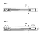
- Fig. 1 is a schematic cross sectional view showing a structure of a thrust needle roller bearing in accordance with Embodiment 1 of the present invention.
- the thrust needle roller bearing 10A has a pair of washers 1, 1, formed of thin steel plates, a plurality of needle rollers rolling between the pair of washers 1, 1, and an annular cage 3 holding the plurality of needle rollers 2 at a prescribed pitch along the circumferential direction.
- Washer 1 has a through hole 1a at the central portion, for inserting a shaft or the like.
- At least washer 1 of thrust needle roller bearing 10A has a nitrogen enriched layer at a surface layer portion, the amount of retained austenite at the surface layer portion is at least 5 volume % and at most 25 volume %, and the austenite grain size number at the surface layer portion is 11 or larger.
- nitrogen concentration at the surface layer portion is at least 0.05 mass % and at most 0.4 mass %.
- not only washer 1 but also needle rollers 2 or cage 3 may have a nitrogen enriched layer at the surface layer portion, the amount of retained austenite at the surface layer portion may be at least 5 volume % and at most 25 volume %, and the austenite grain size number at the surface layer portion may be 11 or larger. Nitrogen concentration at the surface layer portion may be at least 0.05 mass % and at most 0.4 mass %.
- the needle rollers may be arranged in a plurality of rows, as shown in Fig. 2.
- the thrust needle roller bearing 10B has needle rollers 2 arranged in a plurality of rows, including needle rollers 2a on the inner diameter side and needle rollers 2b on the outer diameter side.
- cage 3 is preferably formed by two annular plate members 3a and 3b overlapped to be in contact with each other.
- annular member 3 a has an end portion on the inner diameter side bent and crimped to the side of annular member 3b
- annular member 3b has an end portion on the outer diameter side bent and crimped to the side of annular member 3 a. In this manner, two annular members 3a and 3b can be fixed by crimping and firmly integrated.
- lengths L1 and L2 of needle rollers 2a and 2b arranged in a plurality of rows are the same in this example, the length may be selected to L1 ⁇ L2 or L2 ⁇ L1, dependent on the conditions of use. It is preferred to increase load carrying capacity on the outer diameter side by making the length L2 of the needle roller 2b on the outer diameter side longer, for example, 1.2 times longer, than the length L1 of the needle roller 2a on the inner diameter side.
- thrust needle roller bearing 10B is almost the same as that of thrust needle roller bearing 10A described above and, therefore, the same members are denoted by the same reference characters and description thereof will not be repeated.
- Figs. 3 and 4 show the method of heat treatment for forming the thrust needle roller bearing in accordance with the present invention.
- Fig. 3 shows a pattern of heat treatment representing a method involving primary and secondary quenching.
- Fig. 4 shows a pattern of heat treatment in which the material is cooled to a temperature lower than A 1 transformation point during quenching and thereafter re-heated for final quenching. Both are examples of heat treatment for the thrust needle roller bearing of the present invention.
- steel for a bearing component is heated to a carbonitriding temperature T 1 (845°C) not lower than the A 1 transformation point, and carbonitriding process is performed on the steel for the bearing component.
- a carbonitriding temperature T 1 845°C
- carbon and nitrogen are diffused to the steel base, and carbon is sufficiently absorbed in steel.
- the steel for bearing component is subjected to oil quenching from the process temperature T 1 to a temperature lower than A 1 transformation point.
- tempering at 230°C is performed. The tempering may be omitted.
- the steel for bearing component is heated again to a temperature T 2 (for example, 800°C), which is not lower than the A 1 transformation point and lower than the carbonitriding temperature described above, and kept at the temperature for a process T 2 , subjected to oil quenching from the process temperature T 2 and cooled to a temperature lower than the A 1 transformation point. Then, tempering is performed at 230°C.
- T 2 for example, 800°C
- steel for a bearing component is heated to a carbonitriding temperature T 1 (845°C) not lower than the A 1 transformation point, and carbonitriding process is performed on the steel for the bearing component.
- T 1 carbonitriding temperature
- carbon and nitrogen are diffused to the steel base, and carbon is sufficiently absorbed in steel.
- the steel for bearing component is not subjected to quenching but cooled to a temperature lower than the A 1 transformation point.
- the steel for bearing component is heated again to a temperature T 2 (for example, 800°C), which is not lower than the A 1 transformation point and lower than the carbonitriding temperature described above, and kept at the temperature for a process T 2 , subjected to oil quenching from the process temperature T 2 and cooled to a temperature lower than the A 1 transformation point. Then, tempering is performed at 230°C.
- T 2 for example, 800°C
- a nitrogen enriched layer which is the "carbonitrided layer” is formed at the surface layer portion of the steel for bearing component.
- steel as the material has high carbon concentration, and therefore, sometimes carbon does not readily enter the surface of steel from common carbonitriding atmosphere.
- steel having high carbon concentration (of about 1 mass %), a carburized layer of higher carbon concentration may or may not be generated.
- Cr (chromium) concentration nitrogen concentration is as low as about 0.020 mass% in typical steel. Therefore, a nitrogen enriched layer is definitely formed regardless of the carbon concentration of material steel. It is needless to say that the nitrogen enriched layer may also be enriched with carbon.
- the heat treatment described above is effective against an early failure caused by surface damage such as surface-originated flaking and also effective against subsurface-originated flaking caused by common rolling contact fatigue dependent on load, while carbonitriding of the surface layer is attained. Therefore, the treatment enables longer life of the thrust needle roller bearing.
- Fig. 5A shows austenite grain size of the bearing steel that has been subjected to the heat treatment pattern shown in Fig. 3.
- Fig. 5B shows austenite grain size of the bearing steel that has been subjected to conventional heat treatment.
- Figs. 6A and 6B illustrate austenite grain size corresponding to Figs. 5A and 5B. From these textures showing the austenite grain size, it can be seen that the conventional austenite grain size has JIS (Japanese Industrial Standard) grain size number 10, whereas the heat treatment in accordance with the present invention provides fine grains of number 12.
- the average grain diameter of Fig. 5A measured by the section method was 5.6 ⁇ m.
- Fig. 7 is a schematic cross sectional view showing a structure of a compressor using the thrust needle roller bearing in accordance with Embodiment 1 of the present invention.
- a double-sided swash plate compressor 100 is shown as the compressor.
- Swash compressor 100 is structured such that by the rotation of a swash plate 103 fixed on a main shaft 104, a piston 107 reciprocates with a shoe 109 sliding on swash plate 103.
- main shaft 104 having swash plate 103 fixed thereon is rotatably supported by means of a radial bearing 105.
- a plurality of cylinder bores 106 are formed at equally spaced positions in the circumferential direction, and a double-ended piston 107 is slidably contained in each bore 106.
- a recessed portion 108 is formed to cross over the circumferential portion of swash plate 103, and on axially opposing surfaces of recessed portion 108, spherical seats are formed, on which a spherical or semi-spherical shoe 109 is seated.
- Shoe 109 is interposed between swash plate 103 and piston 107, and functions to convert rotational motion of swash plate 103 smooth to reciprocating motion of piston 107.
- Swash plate 103 is fixed on main shaft 104 and rotates with main shaft 104. As described above, swash plate 103 functions to cause reciprocating motion of piston 107. Therefore, thrust load generates along the axial direction of main shaft 104. Therefore, thrust needle roller bearing 10B is used as a support structure to receive the thrust load. As described above, thrust needle roller bearing 10B has a pair of washers 1, 1, needle rollers 2a, 2b arranged in a plurality of rows, and a cage 3. One of the pair of washers 1 is mounted on swash plate 103 and the other of the pair of washers 1 is mounted on the side of housing 102.
- a double-sided swash plate compressor has been described as the compressor.
- the thrust needle roller bearing of the present invention is also applicable to other types of swash plate compressors or scroll type compressors.
- the swash plate compressors of the other type may include a one-sided swash plate compressor and a variable capacity, one-sided swash plate compressor.
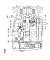
- thrust needle roller bearing 10B of a plurality of rows in accordance with the present embodiment is arranged as a support structure to receive the thrust load, between a coupling member 211 and a housing 202 and between coupling member 211 and a swash plate 203, as shown in Fig. 8.
- Coupling member 211 is a member for coupling swash plate 203 with piston 207.
- swash plate 203 rotates with the rotation of main shaft 204, and coupling member 211 swings accordingly, so that through a piston rod 215, piston 207 reciprocates in the cylinder.
- thrust needle roller bearing 10B of a plurality of rows in accordance with the present embodiment is arranged as a support structure to receive the thrust load, between a journal 303 corresponding to the swash plate and a piston support 312, as shown in Fig. 9. Further, thrust needle roller bearing 10B of a plurality of rows in accordance with the present embodiment is arranged as a support structure to receive the thrust load, between a housing 302 and a sleeve 314 of a main shaft 304.
- journal 303 (swash plate) rotates with the rotation of main shaft 304, and piston support swings accordingly, so that through a piston rod 315, piston 307 reciprocates in the cylinder.
- the angle of inclination of journal 303 can be changed by sliding sleeve 314 coupled to drive pin 313 in the axial direction with respect to the main shaft 304, whereby the capacity can be changed.
- thrust needle roller bearing 10B of a plurality of rows is used in a compressor of a car air-conditioner
- thrust needle roller bearing 10A of a single row shown in Fig. 1 may be used in place of thrust needle roller bearing 10B of a plurality of rows.
- a thrust needle roller bearing is used as a support structure receiving thrust load of a compressor for a car air-conditioner has been described.
- the thrust needle roller bearing of the present invention may be used, in addition to the application above, as a support structure receiving thrust load of a manual transmission.
- Fig. 10 is a schematic cross sectional view showing a support structure receiving thrust load of an automatic transmission in accordance with Embodiment 2 of the present invention.
- an automatic transmission typically consists of a torque converter 500 and a planetary gear mechanism (not shown).
- Torque converter 500 mainly has an impeller 501, a stator 502 and a turbine 503.
- the support structure receiving the thrust load of an automatic transmission in accordance with the present embodiment is a thrust needle roller bearing 510 mounted, for example, between impeller 501 and stator 502, and between stator 502 and turbine 503.
- impeller 501 coupled to an output shaft of an engine and turbine 503 coupled to an input shaft of the automatic transmission are arranged opposite to each other.
- stator 502 is attached to a stator shaft fixed on a casing, by means of a one-directional clutch 504.
- stator 502 changes the direction of liquid flow to exert a forward rotational force to impeller 501, so as to amplify transmission torque.
- Thrust needle roller bearing 510 between impeller 501 and stator 502 has needle rollers 2, cage 3 and washers 505a and 505b. Washer 505a is mounted on an impeller hub 501b and washer 505b is mounted on the side of stator 502.
- Thrust needle roller bearing 510 between stator 502 and turbine 503 has needle rollers 2, two cages 3 and washers 506a and 506b. Washer 506a is mounted on a turbine hub 503b and washer 506b is mounted on the side of stator 502.
- each of the thrust needle roller bearings 510 mounted between impeller 510 and stator 502 and between stator 502 and turbine 503 is implemented by the thrust needle roller bearing 10A shown in Fig. 1 or thrust needle roller bearing 10B shown in Fig. 2.
- Washers 505a and 505b and 506a and 506b each correspond to washer 1 of thrust needle roller bearings 10A and 10B.
- the structure of thrust needle roller bearing 510 and the method of heat treatment performed on each member are the same as those of Embodiment 1, and therefore, description thereof will not be repeated.
- Embodiment 2 a support structure receiving thrust load at a portion of torque converter of an automatic transmission has been described.
- the thrust needle roller bearing in accordance with Embodiment 2 above may be used as a thrust needle roller bearing receiving the thrust load at a gear mechanism portion of the automatic transmission.
- the thrust needle roller bearing of Embodiment 1 is applied to the support structure receiving the thrust load at the gear mechanism portion of the automatic transmission will be described.
- Fig. 11 is a schematic cross sectional view showing a support structure receiving the thrust load at the gear mechanism of the automatic transmission in accordance with Embodiment 3 of the present invention.
- a shaft 551 is a main shaft, rotatbly supported by front and rear bearings 553 in a case 552.
- a sync-hub 554 is provided, and adjacent to one side thereof, an idle gear is provided rotatably, with a roller bearing 558 interposed.
- Idle gear 555 serves as a three-speed main gear, and has a clutch gear 555a on the side of sync-hub 554.
- a diameter-expanded portion 559 is formed, and on the right side of diameter-expanded portion 559, another idle gear 557 is rotatably provided on shaft 551 with a roller bearing interposed, to be in contact with a right side step surface 559a.
- Idle gear 557 serves as a two-speed main gear to be engaged/disengaged with another sync-hub.
- a shaft 561 is a counter shaft, and rotatably supported in case 552 by a bearing such as a bearing 563, parallel to shaft 551 described above.
- gears 565 and 567 are provided in fixed state, to be engaged with idle gears 555 and 557 described above.
- a scissors gear (an intervening gear) 568 having the same diameter and slightly different number of teeth as idle gear 555 is provided rotatably on shaft 551, in contact with the widthwise surface of idle gear 555.
- Idle gear 555 and scissors gear 568 engage with the same gear 565 of shaft 561 as the counter shaft. What is necessary for scissors gear 568 is that it can engage with the same gear 565 as the idle gear 555.
- pitch circle, addendum circle and dedendum circle all have the same diameters as those of idle gear 555.
- the difference in number of teeth between scissors gear 568 and idle gear 555 is at least one.
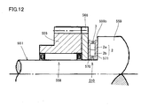
- thrust needle roller bearing 510 is interposed as the support structure.
- thrust needle roller bearing 510 has needle rollers 2, cage 3 and washer 1.
- a gear side washer 570 in contact with the scissors gear 568 described above of the thrust needle roller bearing 510 is rotatable about shaft 551, and in most cases, a washer 571 in contact with the left side step surface 559b of diameter expanded portion 559 is fixed by a key or the like on shaft 551.
- needle rollers 2 include needle rollers 2a and 2b arranged in a plurality of rows.
- Embodiments 2 and 3 Although examples of automatic transmission have been described in Embodiments 2 and 3, the present invention is widely applicable to a thrust support structure used for overall transmissions, and particularly applicable to a thrust support structure used in oil (lubricant oil) with an additive of a transmission.
- oil lubricant oil
- the present invention is not limited thereto, and it may be applied at other portions of the automatic transmission that receive thrust.
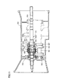
- Fig. 13 is a schematic cross sectional view showing a support structure for a continuously variable transmission in accordance with Embodiment 4 of the present invention.
- a driving force generated by an engine (not shown) is transmitted from a crank shaft (not shown) through a torque converter (not shown) and a forward/backward switching mechanism 610 to a continuously variable transmission 600.
- Forward/backward switching mechanism 610 has a planetary gear mechanism and multiple disk clutches 615, 616.
- Planetary gear mechanism has a ring gear 613a fixed on a shaft 601a through a support member 613, a sun gear 601b fixed on a primary shaft 601, and a planetary pinion 612a rotatably supported on a support member 612. Planetary pinion 612a engages with each of ring gear 613a and sun gear 601b.
- Multiple disk clutch 615 is mounted as a backward brake between an outer circumference of support member 612 and a housing 606.
- Multiple disk clutch 616 is mounted as a forward clutch between an outer circumference of primary shaft 601 and an inner circumference of support member 613.
- a mechanism (not shown) that can apply hydraulic pressure to each of multiple disk clutches 615 and 616 is provided.
- Nonstep variable speed gear 600 has an input side primary shaft 601 coupled to forward/backward switching mechanism 610, a primary pulley 602 provided on primary shaft 601, an output side secondary shaft 603 parallel to primary shaft 601, a secondary pulley 604 provided on secondary shaft 603, and a belt wound around both primary and secondary pulleys 602 and 604.
- Primary pulley 602 has a fixed pulley 602a fixed on primary shaft 601, and a movable pulley 602b mounted slidable along the axial direction on primary shaft 601 by means of a ball spline or the like. By the sliding of movable pulley 602b in the axial direction, an interval between cone surfaces of the pulley, that is, a pulley groove width, can be varied.
- Secondary pulley 604 has a fixed pulley 604a fixed on secondary shaft 603, and a movable pulley 604b mounted slidable along the axial direction on secondary shaft 604b by means of a ball spline or the like. By the sliding of movable pulley 604b in the axial direction, an interval between cone surfaces of the pulley, that is, a pulley groove width, can be varied.
- thrust needle roller bearing 10 is provided to receive thrust load on input side shaft 601a and primary shaft 601 as well as output side secondary shaft 603.
- Fig. 14 is a cross sectional view showing, in enlargement, the portion P of Fig. 13, illustrating how the thrust needle roller bearing is arranged.
- thrust needle roller bearing 10 is arranged, for example, between an inner ring of roller bearing 611 rotatably supporting primary shaft 601 and support member 612, between support member 612 and sun gear 601b, between sun gear 601b and support member 613, and between support member 613 and housing 606.
- Each thrust needle roller bearing 10 has needle rollers 2 and two cages 3, 4 for holding needle rollers 2.
- the needle rollers include needle rollers 2a, 2b in a plurality of rows.
- Each thrust needle roller bearing 10 of the present embodiment is implemented by thrust needle roller bearing 10B shown in Fig. 2. Alternatively, it may be implemented by thrust needle roller bearing 10A shown in Fig. 1.
- the structure of thrust needle roller bearing 10 and the method of heat treatment performed on each member are the same as those of Embodiment 1, and therefore, description thereof will not be repeated.
- Fig. 15 is a schematic cross sectional view showing a structure of a manual transmission in accordance with Embodiment 5 of the present invention.
- a manual transmission 650 is a normally meshing type manual transmission, mainly having four thrust needle roller bearings 10A, an input shaft 661, an output shaft 662, a counter shaft 663, gears 664a to 664k, and a housing 665.
- Input shaft 661 is rotatably supported by a roller bearing 660A in housing 665.
- a gear 664a is formed, and on an inner circumference, a gear 664b is formed.
- Output shaft 662 is rotatably supported by a roller bearing 660B in housing 665 on one side (left side in the figure), and rotatably supported by a roller bearing 660C on input shaft 661 on the other side (right side in the figure).
- gears 664c to 664g are mouted.
- Gears 664c and 664d are formed on the outer and inner circumference of one same member.
- the member on which gears 664c and 664d are formed is rotatably supported by a roller beraing 660D on output shaft 662.
- Gear 664e is attached to output shaft 662 to rotate with output shaft 662 and slidable in the axial direction of output shaft 662.
- Each of gears 664f and 664g is formed on an outer circumference of one same member.
- the member on which gears 664f and 664g are formed is attached to output shaft 662 to rotate with output shaft 662 and slidable in the axial direction of output shaft 662.
- gear 664f can mesh with gear 664b
- gear 664g can mesh with gear 664d.
- Counter shaft 663 has gears 664h to 664k and the like. Between counter shaft 663 and housing 665, four thrust needle roller bearing 10A are arranged, by which load (thrust load) in the axial direction of counter shaft 663 is supported. Gears 664h and 664a are normally meshed with each other, and gears 664i and 664c are normally meshed with each other. When gear 664e slides to the left side in the figure, gear 664j can mesh with gear 664e. When gear 664e slides to the right side in the figure, gear 664k can mesh with gear 664e.
- gear 664f does not mesh with gear 664b
- gear 664g does not mesh with gear 664d
- gear 664e meshes with gear 664j
- driving force of input shaft 661 is transmitted through gears 664a, 664h and gears 664j and 664e to output shaft 662. This realizes, for example, the first speed.
- gear 664g meshes with gear 664d
- gear 664e does not mesh with gear 664j
- driving force of input shaft 661 is transmitted through gears 664a, 664h, 664i, 664c, 664d and 664g to output shaft 662. This realizes, for example, the second speed.
- the support structure receiving thrust load of manual transmission 650 has four thrust needle roller bearings 10A that receive thrust load of counter shaft 663.
- Each of the thrust needle roller bearings 10A is implemented by thrust needle roller bearing 10A shown in Fig. 1. It may be implemented by thrust needle roller bearing 10B shown in Fig. 2.
- the structure of thrust needle roller bearings 10A, 10B and the method of heat treatment performed on each member are the same as those of Embodiment 1, and therefore, description thereof will not be repeated.
- a support structure receiving thrust load of a manual transmission having thrust needle roller bearings 10A for receiving thrust load of counter shaft 663 has been described.
- the support structure receiving thrust load of a manual transmission in accordance with the present invention may have thrust needle roller bearings 10A for receiving thrust load of the input shaft or the output shaft.
- Rollers and washers (having the thickness of at most 3 mm) formed of press-processable steel plates and steel tapes of SUJ2 material (JIS: high carbon chromium bearing steel material), SCM415M (JIS: chromium-molybdenum steel) and S70C (JIS: carbon steel material for machine structural purpose) were prepared.
- SUJ2 material JIS: high carbon chromium bearing steel material
- SCM415M JIS: chromium-molybdenum steel
- S70C JIS: carbon steel material for machine structural purpose
- the heat treatments included heat treatments of heating patterns shown in Figs. 3 and 4 (special heat treatment), carbonitriding process, quenching (quench-hardening, high temperature quench-hardening, double quench-hardening) and carburizing process.
- the objects were kept in a mixed gas atmosphere of an RX gas and an ammonia gas, at 840°C for a prescribed time period for carbonitriding, subjected to primary quenching from that temperature, and tempered at 230°C. Thereafter, the temperature was again increased to 800°C, which is lower than the carbonitriding temperature, the components were kept at that temperature for a prescribed time period, subjected to secondary quenching, and then tempered at 230°C.
- the objects were kept at 840°C for a prescribed time period for carbonitriding, thereafter quenched from that temperature and tempered at 230°C. Then, the temperature was again increased to 840°C, the components were kept at that temperature for a prescribed time period, subjected to quenching, and tempered at 230°C.
- the objects were kept at 850°C for a prescribed time period for carburization, subjected to quenching from that temperature, and then tempered at 230°C.
- the objects were kept at 850°C for a prescribed time period, subjected to quenching from that temperature, and then tempered at 230°C.
- the objects were kept at 880°C for a prescribed time period, subjected to quenching from that temperature, and then tempered at 230°C.
- the objects were kept at 840°C for a prescribed time period, subjected to primary quenching from that temperature, and then tempered at 230°C. Then, the temperature was again increased to 840°C, the objects were kept at that temperature for a prescribed time period, subjected to secondary quenching from that temperature, and tempered at 230°C.
- Crystal grain size numbers, amount of retained austenite and nitrogen content at the surface layer of the washers subjected to the processes above are as shown in Table 1.
- Crystal grain size was measured by the method of austenite grain size determination in accordance with JIS G 0551. Average values among ten test samples formed under the same conditions were found.
- the amount of retained austenite was measured by X-ray diffraction method, at a depth of 0.05 mm from the surface at four positions of the washer surface. Further, average values among ten test samples (10 samples x 4 positions) formed under the same conditions were found.
- test samples subjected to heat treatments other than the special heat treatment cannot attain one of or both of austenite grain size number of 11 or higher and amount of retained austenite of at least 5 volume % and at most 25 volume %.
- the thrust needle roller bearings having washers subjected to the special heat treatment have improved L10 life (number of loaded operation at which 90 % of sample thrust needle roller bearings could be used without breakage), and have longer life, as compared with thrust needle roller bearings having washers not subjected to the special heat treatment.
- L10 life can further be improved when not only washers but rollers are subjected to the special heat treatment.
- the present invention is specifically directed to a thrust needle roller bearing for a compressor of a car air-conditioner and a transmission (manual transmission, automatic transmission and continuously variable transmission). Further, the present invention is directed to a long life support structure for a continuously variable transmission, having a thrust needle roller bearing resistant to an early failure caused by surface damage such as surface-originated flaking and also resistant to common, load dependent rolling contact fatigue.
Landscapes
- Engineering & Computer Science (AREA)
- General Engineering & Computer Science (AREA)
- Mechanical Engineering (AREA)
- Manufacturing & Machinery (AREA)
- Rolling Contact Bearings (AREA)
Abstract
Description
- The present invention relates to a thrust needle roller bearing, a support structure receiving thrust load of a compressor for car air-conditioner, a support structure receiving thrust load of an automatic transmission, a support structure for a continuously variable transmission and a support structure receiving thrust load of a manual transmission.
- A thrust needle roller bearing consists of needle rollers, a cage and a washer, in which the needle rollers are in line-contact with the washer. Therefore, the bearing advantageously attains high load carrying capacity and high rigidity, for its small projection area. Therefore, a thrust needle roller bearing is used in a support structure of a compressor for car air-conditioner and a support structure of a transmission (manual transmission, automatic transmission and continuously variable transmission).
- Such a thrust needle roller bearing is disclosed, for example, in Patent Document 1 (
Japanese Patent Laying-Open No. 2002-70872 - Oil used in a compressor for a car air-conditioner has low viscosity, and the amount of oil is made small in order to improve compressor performance (cooling performance). As the bearing is used under such severe, low viscosity lubrication conditions, the bearing might possibly fail at an early stage because of surface damage, such as surface-originated flaking, if there is much differential slip at the roller.
- Conventionally, auto manufacturers and manufacturers of automatic transmissions sometimes use oil with an additive, in view of energy saving. The oil with such an additive has lower lubrication performance on the bearing, and therefore, improvement of existing thrust bearings involving much differential slip at the rollers has been desired, from the viewpoint of surface damage such as surface-originated flaking.
- There is a tendency that compressors for car air-conditioner and transmissions are used under higher load, and therefore, improvement of existing bearings is also desirable from the viewpoint of subsurface-originated flaking caused by common load-dependent rolling contact fatigue.
- Therefore, a bearing of long life that is resistant to an early failure caused by surface damage such as surface-originated flaking and resistant also to subsurface-originated flaking caused by common load-dependent rolling contact fatigue is desired.
- Patent Document 1:
Japanese Patent Laying-Open No. 2002-70872 - Conventionally, as a material for the washer of a thrust needle roller bearing, readily processable and available steel plate and steel tape material that allows press-processing, including low carbon structural steel, cold-rolled steel plate, medium carbon steel or bearing steel has been used. When low carbon structural steel, cold-rolled steel plate or steel tape is used, carburization or carbonitriding process is performed as heat treatment of the washer, and when medium carbon steel or bearing steel is used, bright quenching or induction hardening is performed.
- Bearing steel is used as the material of the roller of a conventional thrust needle roller bearing, and bright quenching or induction hardening is performed as heat treatment.
- In a thrust needle roller bearing, heat caused by differential slip at the roller may induce damage such as surface-originated flaking. Enforcement of the washer against the surface damage including the surface-originated flaking is desired.
- Further, under heavy load conditions, subsurface-originated flaking also occurs because of common load-dependent rolling contact fatigue, and longer life is desired.
- The present invention was made in view of the foregoing and an object is to provide a long life thrust needle roller bearing having at least washer characteristic changed to be resistant to an early failure caused by surface damage such as surface-originated flaking and resistant also to common load-dependent rolling contact fatigue.
- The present invention was made in view of the foregoing and another object is to provide a long life support structure receiving thrust load of a compressor for car air-conditioner, having at least washer characteristic changed to be resistant to an early failure caused by surface damage such as surface-originated flaking and resistant also to common load-dependent rolling contact fatigue.
- The present invention was made in view of the foregoing and a further object is to provide a long life support structure receiving thrust load of an automatic transmission, of which thrust needle roller bearing is resistant to an early failure caused by surface damage such as surface-originated flaking and resistant also to common load-dependent rolling contact fatigue.
- The present invention was made in view of the foregoing and a still further object is to provide a long life support structure for a continuously variable transmission, of which thrust needle roller bearing is resistant to an early failure caused by surface damage such as surface-originated flaking and resistant also to common load-dependent rolling contact fatigue.
- The present invention was made in view of the foregoing and a still further object is to provide a long life support structure receiving thrust load of a manual transmission, of which thrust needle roller bearing is resistant to an early failure caused by surface damage such as surface-originated flaking and resistant also to common load-dependent rolling contact fatigue.
- The present invention provides a thrust needle roller bearing having a washer formed of a thin steel plate and needle rollers, wherein at least the washer has a nitrogen enriched layer at a surface layer portion, amount of retained austenite in the surface layer portion is at least 5 volume % and at most 25 volume %, and austenite grain size number of the surface layer portion is 11 or higher.
- In the thrust needle roller bearing described above, preferably, nitrogen content of the surface layer portion is in the range of 0.1 mass % to 0.7 mass %.
- The support structure receiving thrust load of a compressor for a car air-conditioner in accordance with the present invention is a support structure receiving thrust load of a compressor for a car air-conditioner in which a swash plate rotates as a main shaft rotates and a piston swings accordingly, including a thrust needle roller bearing receiving thrust load generated by the rotation of the swash plate, having a washer formed of a thin steel plate and needle rollers, wherein at least the washer has a nitrogen enriched layer at a surface layer portion, amount of retained austenite in the surface layer portion is at least 5 volume % and at most 25 volume %, and austenite grain size number of the surface layer portion is 11 or higher.
- In the support structure receiving thrust load of a compressor for a car air-conditioner, preferably, nitrogen content of the surface layer portion is in the range of 0.1 mass % to 0.7 mass %.
- The support structure receiving thrust load of an automatic transmission in accordance with the present invention is a support structure receiving thrust load of an automatic transmission including a torque converter having an impeller and a turbine opposite to each other with a stator in between, including a thrust needle roller bearing having a washer formed of a thin steel plate and needle rollers, at least between the stator and the impeller or between the stator and the turbine. At least the washer has a nitrogen enriched layer at a surface layer portion, amount of retained austenite in the surface layer portion is at least 5 volume % and at most 25 volume %, and austenite grain size number of the surface layer portion is 11 or higher.
- In the support structure receiving thrust load of an automatic transmission, preferably, nitrogen content of the surface layer portion is in the range of 0.1 mass % to 0.7 mass %.
- The support structure for a continuously variable transmission in accordance with the present invention is a support structure for a continuously variable transmission in which rotation of an input shaft is changed in a nonstep manner and transmitted to an output shaft. A thrust needle roller bearing receiving thrust load generated by the rotation either of the input shaft or the output shaft has a washer formed of a thin steel plate and needle rollers, at least the washer has a nitrogen enriched layer at a surface layer portion, amount of retained austenite in the surface layer portion is at least 5 volume % and at most 25 volume %, and austenite grain size number of the surface layer portion is 11 or higher.
- In the support structure for a continuously variable transmission, preferably, nitrogen content of the surface layer portion of the thrust needle roller bearing is in the range of 0.1 mass % to 0.7 mass %.
- The support structure receiving thrust load of a manual transmission in accordance with the present invention is a support structure receiving thrust load of a manual transmission allowing, by engagement between a gear of an input shaft and a gear of a counter shaft and engagement between a gear of the counter shaft and a gear of an output shaft, stepwise change of speed of rotation of the output shaft from the speed of rotation of the input shaft, including a thrust needle roller bearing receiving thrust load of any of the input shaft, the counter shaft and the output shaft, having a washer formed of a thin steel plate and needle rollers, wherein at least the washer has a nitrogen enriched layer at a surface layer portion, amount of retained austenite in the surface layer portion is at least 5 volume % and at most 25 volume %, and austenite grain size number of the surface layer portion is 11 or higher.
- In the support structure receiving thrust load of a manual transmission, preferably, nitrogen content of the surface layer portion of the thrust needle roller bearing is in the range of 0.1 mass % to 0.7 mass %.
- In the thrust needle roller bearing in accordance with the present invention, the washer material is adapted to have fine crystal grain size and high heat resistance, and therefore, life defined by surface-originated flaking (surface damage such as peeling and smearing) and life defined by subsurface-originated flaking can both be improved.
- In the support structure receiving thrust load of a compressor for a car air-conditioner in accordance with the present invention, the washer material is adapted to have fine crystal grain size and high heat resistance, and therefore, life defined by surface-originated flaking (surface damage such as peeling and smearing) and life defined by subsurface-originated flaking can both be improved.
- In the support structure receiving thrust load of an automatic transmission in accordance with the present invention, the washer material of the thrust needle roller bearing is adapted to have fine crystal grain size and high heat resistance, and therefore, life defined by surface-originated flaking (surface damage such as peeling and smearing) and life defined by subsurface-originated flaking can both be improved.
- In the support structure for a continuously variable transmission in accordance with the present invention, the washer material of the thrust needle roller bearing is adapted to have fine crystal grain size and high heat resistance, and therefore, life defined by surface-originated flaking (surface damage such as peeling and smearing) and life defined by subsurface-originated flaking can both be improved.
- In the support structure receiving thrust load of a manual transmission in accordance with the present invention, the washer material of the thrust needle roller bearing is adapted to have fine crystal grain size and high heat resistance, and therefore, life defined by surface-originated flaking (surface damage such as peeling and smearing) and life defined by subsurface-originated flaking can both be improved.
- Specifically, by devising and adjusting processing and heat treatment of the material such as bearing steel and medium carbon steel, a carbonitrided texture (nitrogen enriched layer) reliably having autstenite grain size number of 11 or higher can be obtained. This texture significantly increases resistance to generation and development of cracks. As a result, heat generation at a surface layer caused by slipping or surface cracks caused by tangential force can be suppressed. Further, the inventors have found that significantly longer life can be attained as regards cracks caused by subsurface-originated flaking.
- Considering the surface damage such as the surface-originated flaking, it is particularly essential that a heat-resistant, nitrogen enriched layer having fine carbide deposited at the surface layer portion is formed. In the present invention, a nitrogen enriched layer is formed, and in addition, at least 5 volume % of retained austenite exists at the surface layer portion and the austenite at the surface layer portion is as fine as to have austenite grain size number of 11 or higher. Thus, surface damage such as surface-originated flaking can be suppressed.
- The retained austenite existing in the nitrogen enriched layer at the surface layer portion is a factor that decreases surface hardness. Therefore, it is necessary to decrease the amount of retained austenite than a carbonitrided article, through quenching after carbonitriding process, by re-heating to a temperature lower than the temperature of carbonitriding process. In the present invention, the retained austenite at the surface layer portion is reduced to 25 volume % or lower, and therefore, decrease in surface hardness can be suppressed.
- With the above-described micro-texture as a basic component, further processing or heat treatment is performed to exert compressive stress on the surface layer described above, to further increase hardness, whereby longer life can be attained. As the processing or heat treatment, a technique such as (b1) shot peening, (b2) barreling, (b3) rolling, (b4) carburization + carbonitriding, (b5) carbonitriding + sub zero treatment or (b6) carbonitriding + secondary quenching + sub zero treatment may be applied by itself, or combination of techniques (b1) to (b6) may be applied.
- At least one of the washer and the roller may be subjected to the carbonitriding process at A1 transformation point or higher, cooled to a temperature lower than the A1 transformation point, thereafter heated to a quenching temperature lower than the temperature of carbonitriding process, and then quenched from that quenching temperature.
- In the process of cooling to a temperature lower than the A1 transformation point after carbonitriding at the carbonitriding temperature, the temperature may be lowered to room temperature by oil quenching, or cooled to a temperature at which austenite transformation is completed at least to a prescribed value. By the manufacturing method described above, a metal texture having a nitrogen enriched layer, fine austenite grains and containing appropriate amount of retained austenite can be obtained. Consequently, life defined by surface-originated flaking and life defined by subsurface-originated flaking can both be improved. Further, a thrust needle roller bearing, a support structure receiving thrust load of a compressor of a car air-conditioner, a support structure receiving thrust load of an automatic transmission, a support structure for a continuously variable transmission and a support structure receiving thrust load of a manual transmission can be provided, in which dimensional variation with aging is suppressed.
- As described above, the nitrogen enriched layer is formed by carbonitriding process, and the nitrogen enriched layer may or may not be carbon-enriched.
- In such a micro-texture, very fine austenite crystal grains can be obtained, as it is once cooled after carbonitriding process and quenched from a quenching temperature lower than the temperature of carbonitriding process. The process of heating to the quenching temperature lower than the temperature of carbonitriding process and quenching is sometimes referred to as secondary quenching or final quenching, in view of the order of processing.
- The quenching temperature mentioned above may be in a temperature range where carbide and/or nitride and austenite phase co-exist at least in the surface layer portion of the carbonitrided steel.
- As the heating temperature at the time of quenching is lower than the heating temperature of carbonitriding process, the amount of carbide and/or nitride not-yet-absorbed at the surface layer portion subject to the effect of carbonitriding process is increased than in the carbonitriding process. Therefore, when the quenching temperature is in the above-described co-existing temperature range, the ratio of not-yet-absorbed carbide/nitride at the quenching temperature is increased than in the carbonitriding process, and the ratio of austenite amount decreases. Further, it can be seen from the binary phase diagram of iron-carbon, in the region where carbide (cementite) and austenite co-exist, that concentration of carbon contained as solid solution in austenite decreases as the quenching temperature decreases. The steel used for a bearing has low content of other alloy element such as Si (silicon) or Mn (manganese) and, therefore, it is possible with sufficiently high accuracy to discuss temperature ranges and generated layers, using the iron-carbon binary phase diagram. Further, similar to carbon, nitrogen is contained as interstitial solid solution in iron, and generates nitride with iron similar to cementite in a prescribed temperature range. Therefore, it can be regarded as the same as carbon, in approximation.
- When heated to the quenching temperature, there is a large amount of carbide and/or nitride that is not yet absorbed and prevents growth of austenite grains, and hence, the austenite grains come to be very fine. Further, the texture transformed by quenching from austenite to martensite has slightly lower carbon concentration when subjected to the heat treatment described above, and therefore, the texture comes to have slightly higher toughness than the texture quenched from the carbonitriding temperature. Specifically, the quenched texture comes to have (cl) not-yet-absorbed carbide and/or nitride of larger amount than the conventional example and (c2) carbon concentration lower than the conventional example.
- The quenching temperature mentioned above may be set to 780°C to 830°C. This temperature range may be applied to almost every steel material, so that management of quenching temperature is simplified.
- Further, at least one of the washer and roller described above may be subjected to cold working such as pressing, prior to the carbonitriding process.
- By performing such cold working, nucleation density of austenite grains at the time of heat treatment increases, and very fine texture can be obtained.
- Further, to at least one of the washer and the roller described above, compressive stress of at least 500 MPa may be applied.
- As already described, with the above-described micro-texture as a basic component, further processing or heat treatment may be performed to exert compressive stress on the surface layer described above, whereby longer life can be attained.
- In the present specification, austenite grain size number refers to the grain size number of austenite defined by the method of austenite grain size determination in accordance with JIS G 0551.
- In the present specification, the austenite grain refers to austenite crystal grain that is phase-transformed during quenching, and refers to the one remaining even after transformation by cooling to martensite, as the past history.
- The austenite crystal grains should have grain boundary that can be observed by performing a process such as etching to expose the grain boundary on a metallographic sample of the object member. The grains are also referred to as old austenite grains, meaning the grain boundary at a heated time point immediately before low-temperature quenching. As to the measurement, an average value of grain numbers of JIS standard may be converted as an equivalent to the average grain diameter, or a section method or the like may be used, in which an average of distances at which straight lines in random direction overlapped on the metallographic sample meet the grain boundary is calculated and multiplied by a correction coefficient to obtain the two-dimensional to three-dimensional distance.
- The retained austenite is measured using various X-ray diffraction methods, in which, by way of example, diffraction intensity of appropriate Miller indices of the austenite phase is found, and compared with diffraction intensity of appropriate Miller indices of the ferrite phase. At this time, height of diffraction peak may be used, or area of diffraction peak may be used. Alternatively, it can be measured utilizing the fact that the austenite phase is non-magnetic and the ferrite phase is ferromagnetic, by finding magnetizing force using a magnetic balance. It can also be measured easily by a commercially available measuring device.
- At the time of low temperature quenching, the austenite phase transforms to martensite and the like. The retained austenite refers to austenite left untransformed after the temperature is cooled to the room temperature, between adjacent martensite bundles or the like that transform along different crystal faces. Therefore, it is not directly related to the austenite crystal grains of which range of average grain size is limited as described above.
- It is not effective when the nitrogen content at the surface layer portion is smaller than 0. 1 mass %, and rolling contact fatigue life decreases particularly in the presence of foreign matters. When the nitrogen content is larger than 0.7 mass %, pores referred to as voids are generated, or the amount of retained austenite becomes too large to attain sufficient hardness, so that the life becomes shorter. The nitrogen content of the nitrogen enriched layer formed in the washer is represented by a value at the surface layer of 50 µm from the surface of washer after grinding, which may be measured by an EPMA (Electron Probe Micro-Analysis).
-
- Fig. 1 is a schematic cross sectional view showing a structure of a thrust needle roller bearing in accordance with
Embodiment 1 of the present invention. - Fig. 2 is a schematic cross sectional view showing a structure of a thrust needle roller bearing having rollers arranged in a plurality of rows, as another form of the thrust needle roller bearing in accordance with
Embodiment 1 of the present invention. - Fig. 3 is an illustration of a method of heat treatment of the thrust needle roller bearing in accordance with the present invention.
- Fig. 4 is an illustration of a modification of the method of heat treatment of the thrust needle roller bearing in accordance with the present invention.
- Fig. 5A shows micro-texture, particularly austenite grains of the bearing component in accordance with the present invention.
- Fig. 5B shows micro-texture, particularly austenite grains of a conventional bearing component.
- Fig. 6A is an illustration corresponding to Fig. 5A, showing austenite grain boundaries.
- Fig. 6B is an illustration corresponding to Fig. 5B, showing austenite grain boundaries.
- Fig. 7 is a schematic cross sectional view showing a structure of a double-sided swash plate compressor.
- Fig. 8 is a schematic cross sectional view showing a structure of a one-sided swash plate compressor.
- Fig. 9 is a schematic cross sectional view showing a structure of a variable capacity, one-sided swash plate compressor.
- Fig. 10 is a schematic cross sectional view showing a support structure receiving thrust load of an automatic transmission in accordance with
Embodiment 2 of the present invention. - Fig. 11 is a schematic cross sectional view showing a support structure receiving thrust load at a gear mechanism of an automatic transmission in accordance with
Embodiment 3 of the present invention. - Fig. 12 is a schematic cross sectional view showing, in enlargement, a region P of Fig. 11.
- Fig. 13 is a schematic cross sectional view showing a support structure for a continuously variable transmission in accordance with Embodiment 4 of the present invention.
- Fig. 14 is a cross sectional view showing, in enlargement, a portion P of Fig. 13.
- Fig. 15 is a schematic cross sectional view showing a structure of a manual transmission in accordance with Embodiment 5 of the present invention.
- 1, 505a, 505b, 506a, 506b, 570, 571 washer, 1a through hole, 2, 2a, 2b needle roller, 3 cage, 3 a, 3b annular member, 10, 10A, 10B, 510 thrust needle roller bearing, 100 double-sided swash plate compressor, 102, 202, 302, 606 housing, 103 swash plate, 104 main shaft, 105 radial bearing, 106 cylinder bore, 107 piston, 108 recessed portion, 109 shoe, 200 one-sided swash plate compressor, 203 swash plate, 204, 304 main shaft, 207 piston, 211 coupling member, 215 piston rod, 300 variable capacity swash plate compressor, 303 journal, 307 piston, 312 piston support, 313 drive pin, 314 sleeve, 315 piston rod, 500 torque converter, 501 impeller, 501a impeller blade, 501b impeller hub, 502 stator, 503 turbine, 503a turbine blade, 503b turbine hub, 504 one-directional clutch, 551, 561, 601a shaft, 552 case, 553, 558, 563 bearing, 554 sync-hub, 555, 557 idle gear, 555a clutch gear, 559 diameter expanded shaft portion, 559a right side step surface, 559b left side step surface, 565, 567 gear, 568 scissors gear, 600 nonstep variable speed gear mechanism, 601 primary shaft, 601b sun gear, 602 primary pulley, 602a fixed pulley, 602b movable pulley, 603 secondary shaft, 604 secondary pulley, 604a fixed pulley, 604b movable pulley, 605 belt, 610 forward/backward switching mechanism, 611 roller bearing, 612 support member, 612a planetary pinion, 613 support member, 613a ring gear, 615, 616 multiple-disk clutch, 650 manual transmission, 661 input shaft, 662 output shaft, 663 counter shaft, 664a - 664k gear, 665 housing, 660A ~ 660D roller bearing.
- Embodiments of the present invention will be described with reference to the figures.
- Fig. 1 is a schematic cross sectional view showing a structure of a thrust needle roller bearing in accordance with
Embodiment 1 of the present invention. Referring to Fig. 1, the thrustneedle roller bearing 10A has a pair ofwashers washers annular cage 3 holding the plurality ofneedle rollers 2 at a prescribed pitch along the circumferential direction.Washer 1 has a throughhole 1a at the central portion, for inserting a shaft or the like. - At
least washer 1 of thrustneedle roller bearing 10A has a nitrogen enriched layer at a surface layer portion, the amount of retained austenite at the surface layer portion is at least 5 volume % and at most 25 volume %, and the austenite grain size number at the surface layer portion is 11 or larger. Preferably, nitrogen concentration at the surface layer portion is at least 0.05 mass % and at most 0.4 mass %. - Alternatively, not only
washer 1 but also needlerollers 2 orcage 3 may have a nitrogen enriched layer at the surface layer portion, the amount of retained austenite at the surface layer portion may be at least 5 volume % and at most 25 volume %, and the austenite grain size number at the surface layer portion may be 11 or larger. Nitrogen concentration at the surface layer portion may be at least 0.05 mass % and at most 0.4 mass %. - Though a structure in which the needle rollers are arranged in a single row has been described above, the needle rollers may be arranged in a plurality of rows, as shown in Fig. 2.
- Referring to Fig. 2, the thrust
needle roller bearing 10B hasneedle rollers 2 arranged in a plurality of rows, includingneedle rollers 2a on the inner diameter side andneedle rollers 2b on the outer diameter side. Here,cage 3 is preferably formed by twoannular plate members annular member 3 a has an end portion on the inner diameter side bent and crimped to the side ofannular member 3b, andannular member 3b has an end portion on the outer diameter side bent and crimped to the side ofannular member 3 a. In this manner, twoannular members - Though lengths L1 and L2 of
needle rollers needle roller 2b on the outer diameter side longer, for example, 1.2 times longer, than the length L1 of theneedle roller 2a on the inner diameter side. - Except for the point described above, the structure of thrust
needle roller bearing 10B is almost the same as that of thrustneedle roller bearing 10A described above and, therefore, the same members are denoted by the same reference characters and description thereof will not be repeated. - Next, heat treatment including carbonitriding process performed on at least one bearing component of
washer 1,needle roller 2 andcage 3 of each of thrustneedle roller bearings - Figs. 3 and 4 show the method of heat treatment for forming the thrust needle roller bearing in accordance with the present invention. Fig. 3 shows a pattern of heat treatment representing a method involving primary and secondary quenching. Fig. 4 shows a pattern of heat treatment in which the material is cooled to a temperature lower than A1 transformation point during quenching and thereafter re-heated for final quenching. Both are examples of heat treatment for the thrust needle roller bearing of the present invention.
- Referring to Fig. 3, first, steel for a bearing component is heated to a carbonitriding temperature T1 (845°C) not lower than the A1 transformation point, and carbonitriding process is performed on the steel for the bearing component. At the process temperature T1, carbon and nitrogen are diffused to the steel base, and carbon is sufficiently absorbed in steel. Thereafter, the steel for bearing component is subjected to oil quenching from the process temperature T1 to a temperature lower than A1 transformation point. Thereafter, tempering at 230°C is performed. The tempering may be omitted.
- Thereafter, the steel for bearing component is heated again to a temperature T2 (for example, 800°C), which is not lower than the A1 transformation point and lower than the carbonitriding temperature described above, and kept at the temperature for a process T2, subjected to oil quenching from the process temperature T2 and cooled to a temperature lower than the A1 transformation point. Then, tempering is performed at 230°C.
- Referring to Fig. 4, first, steel for a bearing component is heated to a carbonitriding temperature T1 (845°C) not lower than the A1 transformation point, and carbonitriding process is performed on the steel for the bearing component. At the process temperature T1, carbon and nitrogen are diffused to the steel base, and carbon is sufficiently absorbed in steel. Thereafter, the steel for bearing component is not subjected to quenching but cooled to a temperature lower than the A1 transformation point. Thereafter, the steel for bearing component is heated again to a temperature T2 (for example, 800°C), which is not lower than the A1 transformation point and lower than the carbonitriding temperature described above, and kept at the temperature for a process T2, subjected to oil quenching from the process temperature T2 and cooled to a temperature lower than the A1 transformation point. Then, tempering is performed at 230°C.
- By the carbonitriding process described above, a nitrogen enriched layer, which is the "carbonitrided layer," is formed at the surface layer portion of the steel for bearing component. In the carbonitriding process, steel as the material has high carbon concentration, and therefore, sometimes carbon does not readily enter the surface of steel from common carbonitriding atmosphere. In steel having high carbon concentration (of about 1 mass %), a carburized layer of higher carbon concentration may or may not be generated. On the other hand, though it depends on Cr (chromium) concentration, nitrogen concentration is as low as about 0.020 mass% in typical steel. Therefore, a nitrogen enriched layer is definitely formed regardless of the carbon concentration of material steel. It is needless to say that the nitrogen enriched layer may also be enriched with carbon.
- As compared with common quenching (that is, one quenching following carbonitriding process), the heat treatment described above is effective against an early failure caused by surface damage such as surface-originated flaking and also effective against subsurface-originated flaking caused by common rolling contact fatigue dependent on load, while carbonitriding of the surface layer is attained. Therefore, the treatment enables longer life of the thrust needle roller bearing.
- Fig. 5A shows austenite grain size of the bearing steel that has been subjected to the heat treatment pattern shown in Fig. 3. For comparison, Fig. 5B shows austenite grain size of the bearing steel that has been subjected to conventional heat treatment. Figs. 6A and 6B illustrate austenite grain size corresponding to Figs. 5A and 5B. From these textures showing the austenite grain size, it can be seen that the conventional austenite grain size has JIS (Japanese Industrial Standard)
grain size number 10, whereas the heat treatment in accordance with the present invention provides fine grains of number 12. The average grain diameter of Fig. 5A measured by the section method was 5.6 µm. - Next, a compressor for a car air-conditioner using the thrust
needle roller bearing 10B (Fig. 2) in accordance with the present embodiment will be described. - Fig. 7 is a schematic cross sectional view showing a structure of a compressor using the thrust needle roller bearing in accordance with
Embodiment 1 of the present invention. Referring to Fig. 7, as the compressor, a double-sidedswash plate compressor 100 is shown.Swash compressor 100 is structured such that by the rotation of aswash plate 103 fixed on amain shaft 104, apiston 107 reciprocates with ashoe 109 sliding onswash plate 103. - In a
housing 102,main shaft 104 havingswash plate 103 fixed thereon is rotatably supported by means of aradial bearing 105. Inhousing 102, a plurality of cylinder bores 106 are formed at equally spaced positions in the circumferential direction, and a double-endedpiston 107 is slidably contained in eachbore 106. At the central portion of eachpiston 107, a recessedportion 108 is formed to cross over the circumferential portion ofswash plate 103, and on axially opposing surfaces of recessedportion 108, spherical seats are formed, on which a spherical orsemi-spherical shoe 109 is seated.Shoe 109 is interposed betweenswash plate 103 andpiston 107, and functions to convert rotational motion ofswash plate 103 smooth to reciprocating motion ofpiston 107. -
Swash plate 103 is fixed onmain shaft 104 and rotates withmain shaft 104. As described above,swash plate 103 functions to cause reciprocating motion ofpiston 107. Therefore, thrust load generates along the axial direction ofmain shaft 104. Therefore, thrustneedle roller bearing 10B is used as a support structure to receive the thrust load. As described above, thrustneedle roller bearing 10B has a pair ofwashers needle rollers cage 3. One of the pair ofwashers 1 is mounted onswash plate 103 and the other of the pair ofwashers 1 is mounted on the side ofhousing 102. - In the embodiment above, a double-sided swash plate compressor has been described as the compressor. The thrust needle roller bearing of the present invention, however, is also applicable to other types of swash plate compressors or scroll type compressors. The swash plate compressors of the other type may include a one-sided swash plate compressor and a variable capacity, one-sided swash plate compressor.
- In a one-sided
swash plate compressor 200, thrustneedle roller bearing 10B of a plurality of rows in accordance with the present embodiment is arranged as a support structure to receive the thrust load, between acoupling member 211 and ahousing 202 and betweencoupling member 211 and aswash plate 203, as shown in Fig. 8. Couplingmember 211 is a member for couplingswash plate 203 withpiston 207. Incompressor 200,swash plate 203 rotates with the rotation ofmain shaft 204, andcoupling member 211 swings accordingly, so that through apiston rod 215,piston 207 reciprocates in the cylinder. - In a one-sided swash plate,
variable capacity compressor 300, thrustneedle roller bearing 10B of a plurality of rows in accordance with the present embodiment is arranged as a support structure to receive the thrust load, between ajournal 303 corresponding to the swash plate and apiston support 312, as shown in Fig. 9. Further, thrustneedle roller bearing 10B of a plurality of rows in accordance with the present embodiment is arranged as a support structure to receive the thrust load, between ahousing 302 and asleeve 314 of amain shaft 304. - In
compressor 300, journal 303 (swash plate) rotates with the rotation ofmain shaft 304, and piston support swings accordingly, so that through apiston rod 315,piston 307 reciprocates in the cylinder. Incompressor 300, the angle of inclination ofjournal 303 can be changed by slidingsleeve 314 coupled to drivepin 313 in the axial direction with respect to themain shaft 304, whereby the capacity can be changed. - Though examples in which thrust
needle roller bearing 10B of a plurality of rows is used in a compressor of a car air-conditioner have been described, thrustneedle roller bearing 10A of a single row shown in Fig. 1 may be used in place of thrustneedle roller bearing 10B of a plurality of rows. - In the foregoing, a thrust needle roller bearing is used as a support structure receiving thrust load of a compressor for a car air-conditioner has been described. The thrust needle roller bearing of the present invention may be used, in addition to the application above, as a support structure receiving thrust load of a manual transmission.
- Fig. 10 is a schematic cross sectional view showing a support structure receiving thrust load of an automatic transmission in accordance with
Embodiment 2 of the present invention. Referring to Fig. 10, an automatic transmission typically consists of atorque converter 500 and a planetary gear mechanism (not shown). -
Torque converter 500 mainly has animpeller 501, astator 502 and aturbine 503. The support structure receiving the thrust load of an automatic transmission in accordance with the present embodiment is a thrustneedle roller bearing 510 mounted, for example, betweenimpeller 501 andstator 502, and betweenstator 502 andturbine 503. - In
torque converter 500,impeller 501 coupled to an output shaft of an engine andturbine 503 coupled to an input shaft of the automatic transmission are arranged opposite to each other. Further,stator 502 is attached to a stator shaft fixed on a casing, by means of a one-directional clutch 504. When a liquid under reflux between animpeller blade 501a and aturbine blade 503a each formed to have a bowl shape is returned from the side ofturbine 503 to the side ofimpeller 501 on the inner diameter side,stator 502 changes the direction of liquid flow to exert a forward rotational force toimpeller 501, so as to amplify transmission torque. - Thrust
needle roller bearing 510 betweenimpeller 501 andstator 502 hasneedle rollers 2,cage 3 andwashers Washer 505a is mounted on animpeller hub 501b andwasher 505b is mounted on the side ofstator 502. - Thrust
needle roller bearing 510 betweenstator 502 andturbine 503 hasneedle rollers 2, twocages 3 andwashers Washer 506a is mounted on aturbine hub 503b andwasher 506b is mounted on the side ofstator 502. - In the present embodiment, each of the thrust
needle roller bearings 510 mounted betweenimpeller 510 andstator 502 and betweenstator 502 andturbine 503 is implemented by the thrustneedle roller bearing 10A shown in Fig. 1 or thrustneedle roller bearing 10B shown in Fig. 2.Washers washer 1 of thrustneedle roller bearings needle roller bearing 510 and the method of heat treatment performed on each member are the same as those ofEmbodiment 1, and therefore, description thereof will not be repeated. - In
Embodiment 2 above, a support structure receiving thrust load at a portion of torque converter of an automatic transmission has been described. The thrust needle roller bearing in accordance withEmbodiment 2 above may be used as a thrust needle roller bearing receiving the thrust load at a gear mechanism portion of the automatic transmission. In the following, an example in which the thrust needle roller bearing ofEmbodiment 1 is applied to the support structure receiving the thrust load at the gear mechanism portion of the automatic transmission will be described. - Fig. 11 is a schematic cross sectional view showing a support structure receiving the thrust load at the gear mechanism of the automatic transmission in accordance with
Embodiment 3 of the present invention. - Referring to Figs. 11 and 12, a
shaft 551 is a main shaft, rotatbly supported by front andrear bearings 553 in acase 552. On an outer circumference ofshaft 551, a sync-hub 554 is provided, and adjacent to one side thereof, an idle gear is provided rotatably, with aroller bearing 558 interposed.Idle gear 555 serves as a three-speed main gear, and has aclutch gear 555a on the side of sync-hub 554. On an outer circumference ofshaft 551 on the right side ofidle gear 555 as the three-speed main gear, a diameter-expandedportion 559 is formed, and on the right side of diameter-expandedportion 559, anotheridle gear 557 is rotatably provided onshaft 551 with a roller bearing interposed, to be in contact with a rightside step surface 559a.Idle gear 557 serves as a two-speed main gear to be engaged/disengaged with another sync-hub. - A
shaft 561 is a counter shaft, and rotatably supported incase 552 by a bearing such as abearing 563, parallel toshaft 551 described above. Onshaft 561, gears 565 and 567 are provided in fixed state, to be engaged withidle gears - Between a widthwise surface of
idle gear 555 as the three-speed main gear and a leftside step surface 559b of diameter-expandedportion 559 ofshaft 551, a scissors gear (an intervening gear) 568 having the same diameter and slightly different number of teeth asidle gear 555 is provided rotatably onshaft 551, in contact with the widthwise surface ofidle gear 555.Idle gear 555 and scissors gear 568 engage with thesame gear 565 ofshaft 561 as the counter shaft. What is necessary for scissors gear 568 is that it can engage with thesame gear 565 as theidle gear 555. In the present embodiment, pitch circle, addendum circle and dedendum circle all have the same diameters as those ofidle gear 555. Preferably, the difference in number of teeth between scissors gear 568 andidle gear 555 is at least one. Between scissors gear 568 and the leftside step surface 559b of diameter expandedportion 559, thrustneedle roller bearing 510 is interposed as the support structure. - Similar to
Embodiment 1, thrustneedle roller bearing 510 hasneedle rollers 2,cage 3 andwasher 1. Agear side washer 570 in contact with the scissors gear 568 described above of the thrustneedle roller bearing 510 is rotatable aboutshaft 551, and in most cases, awasher 571 in contact with the leftside step surface 559b of diameter expandedportion 559 is fixed by a key or the like onshaft 551. - In thrust
needle roller bearing 510,needle rollers 2 includeneedle rollers - In this structure, in a shift state where sync-
hub 554 is engaging withclutch gear 555 a ofidle gear 555,shaft 551 andidle gear 555 rotate in synchronization, whileshaft 551 and scissors gear 568 rotate relative to each other, as the number of teeth of scissors gear 568 is made slightly different fromidle gear 555. As a result, relative rotation occurs betweengear side washer 570 andwasher 571 fixed on the side of the shaft of thrustneedle roller bearing 510, andneedle rollers - Though examples of automatic transmission have been described in
Embodiments - Though an example in which the support structure receiving thrust load is mounted between the turbine and the stator and between the stator and the impeller has been described, the present invention is not limited thereto, and it may be applied at other portions of the automatic transmission that receive thrust.
- Fig. 13 is a schematic cross sectional view showing a support structure for a continuously variable transmission in accordance with Embodiment 4 of the present invention. Referring to Fig. 13, a driving force generated by an engine (not shown) is transmitted from a crank shaft (not shown) through a torque converter (not shown) and a forward/
backward switching mechanism 610 to a continuouslyvariable transmission 600. - Forward/
backward switching mechanism 610 has a planetary gear mechanism andmultiple disk clutches shaft 601a through asupport member 613, asun gear 601b fixed on aprimary shaft 601, and aplanetary pinion 612a rotatably supported on asupport member 612.Planetary pinion 612a engages with each of ring gear 613a andsun gear 601b. -
Multiple disk clutch 615 is mounted as a backward brake between an outer circumference ofsupport member 612 and ahousing 606.Multiple disk clutch 616 is mounted as a forward clutch between an outer circumference ofprimary shaft 601 and an inner circumference ofsupport member 613. A mechanism (not shown) that can apply hydraulic pressure to each ofmultiple disk clutches - When hydraulic pressure is applied and multiple disk clutch (forward clutch) 616 is set to the connected state, rotation of
shaft 601 a is transmitted in a forward direction toprimary shaft 601. When hydraulic pressure is applied and multiple disk clutch (backward brake) 615 is set to the connected state, rotation ofshaft 601a is transmitted in a backward direction toprimary shaft 601. This enables forward/backward motion control. - Nonstep
variable speed gear 600 has an input sideprimary shaft 601 coupled to forward/backward switching mechanism 610, aprimary pulley 602 provided onprimary shaft 601, an output sidesecondary shaft 603 parallel toprimary shaft 601, asecondary pulley 604 provided onsecondary shaft 603, and a belt wound around both primary andsecondary pulleys -
Primary pulley 602 has a fixed pulley 602a fixed onprimary shaft 601, and amovable pulley 602b mounted slidable along the axial direction onprimary shaft 601 by means of a ball spline or the like. By the sliding ofmovable pulley 602b in the axial direction, an interval between cone surfaces of the pulley, that is, a pulley groove width, can be varied. -
Secondary pulley 604 has a fixedpulley 604a fixed onsecondary shaft 603, and amovable pulley 604b mounted slidable along the axial direction onsecondary shaft 604b by means of a ball spline or the like. By the sliding ofmovable pulley 604b in the axial direction, an interval between cone surfaces of the pulley, that is, a pulley groove width, can be varied. - By changing the groove width of both pulleys, contact diameter of
belt 605 withpulley 602 and withpulley 604 changes. Consequently, the ratio of winding diameter ofbelt 605 around pulleys 602 and 604 changes. Thus, the rotation ofprimary shaft 601 is transmitted tosecondary shaft 603 with the speed changed in stepless manner. - In the present embodiment, thrust
needle roller bearing 10 is provided to receive thrust load oninput side shaft 601a andprimary shaft 601 as well as output sidesecondary shaft 603. - Fig. 14 is a cross sectional view showing, in enlargement, the portion P of Fig. 13, illustrating how the thrust needle roller bearing is arranged. Referring to Fig. 14, thrust
needle roller bearing 10 is arranged, for example, between an inner ring ofroller bearing 611 rotatably supportingprimary shaft 601 andsupport member 612, betweensupport member 612 andsun gear 601b, betweensun gear 601b andsupport member 613, and betweensupport member 613 andhousing 606. Each thrustneedle roller bearing 10 hasneedle rollers 2 and twocages 3, 4 for holdingneedle rollers 2. The needle rollers includeneedle rollers - Each thrust
needle roller bearing 10 of the present embodiment is implemented by thrustneedle roller bearing 10B shown in Fig. 2. Alternatively, it may be implemented by thrustneedle roller bearing 10A shown in Fig. 1. The structure of thrustneedle roller bearing 10 and the method of heat treatment performed on each member are the same as those ofEmbodiment 1, and therefore, description thereof will not be repeated. - Fig. 15 is a schematic cross sectional view showing a structure of a manual transmission in accordance with Embodiment 5 of the present invention. Referring to Fig. 15, a
manual transmission 650 is a normally meshing type manual transmission, mainly having four thrustneedle roller bearings 10A, aninput shaft 661, anoutput shaft 662, acounter shaft 663,gears 664a to 664k, and ahousing 665. -
Input shaft 661 is rotatably supported by aroller bearing 660A inhousing 665. On an outer circumference ofinput shaft 661, agear 664a is formed, and on an inner circumference, agear 664b is formed. -
Output shaft 662 is rotatably supported by aroller bearing 660B inhousing 665 on one side (left side in the figure), and rotatably supported by aroller bearing 660C oninput shaft 661 on the other side (right side in the figure). Onoutput shaft 662, gears 664c to 664g are mouted. -
Gears roller beraing 660D onoutput shaft 662.Gear 664e is attached tooutput shaft 662 to rotate withoutput shaft 662 and slidable in the axial direction ofoutput shaft 662. - Each of
gears output shaft 662 to rotate withoutput shaft 662 and slidable in the axial direction ofoutput shaft 662. When the member on which gears 664f and 664g are formed slides to the left side in the figure,gear 664f can mesh withgear 664b, and when it slides to the right side in the figure,gear 664g can mesh withgear 664d. -
Counter shaft 663 hasgears 664h to 664k and the like. Betweencounter shaft 663 andhousing 665, four thrustneedle roller bearing 10A are arranged, by which load (thrust load) in the axial direction ofcounter shaft 663 is supported.Gears gear 664e slides to the left side in the figure,gear 664j can mesh withgear 664e. Whengear 664e slides to the right side in the figure,gear 664k can mesh withgear 664e. - The speed changing operation of
manual transmission 650 will be described. - In
manual transmission 650, by the engagement ofgear 664a ofinput shaft 661 andgear 664h ofcounter shaft 663, the rotation ofinput shaft 661 is transmitted to countershaft 663. By engagement ofgears 664i to 664k ofcounter shaft 663 withgears output shaft 662, or withgears output shaft 662, rotation ofcounter shaft 662 is transmitted tooutput shaft 662. Thus, rotation ofinput shaft 661 is transmitted tooutput shaft 662. - When the rotation of
input shaft 661 is transmitted tooutput shaft 662, by changing the gears to be engaged betweeninput shaft 661 andcounter shaft 663 and gears engaging betweencounter shaft 662 andoutput shaft 663, the speed of rotation ofoutput shaft 662 can be changed stepwise from the speed of rotation ofinput shaft 661. Alternatively, by direct engagement ofgear 664b ofinput shaft 661 withgear 664f ofoutput shaft 662 without interposingcounter shaft 663, the rotation ofinput shaft 661 can directly be transmitted tooutput shaft 662. - The speed changing operation of
manual transmission 650 will be described more specifically in the following. Whengear 664f does not mesh withgear 664b,gear 664g does not mesh withgear 664d andgear 664e meshes withgear 664j, driving force ofinput shaft 661 is transmitted throughgears output shaft 662. This realizes, for example, the first speed. - When
gear 664g meshes withgear 664d, andgear 664e does not mesh withgear 664j, driving force ofinput shaft 661 is transmitted throughgears output shaft 662. This realizes, for example, the second speed. - When
gear 664f meshes withgear 664b andgear 664e does not mesh withgear 664j,input shaft 661 is directly coupled tooutput shaft 662 by the engagement betweengear input shaft 661 is directly transmitted tooutput shaft 662. This realizes, for example, the third speed (top). - In the present embodiment, the support structure receiving thrust load of
manual transmission 650 has four thrustneedle roller bearings 10A that receive thrust load ofcounter shaft 663. Each of the thrustneedle roller bearings 10A is implemented by thrustneedle roller bearing 10A shown in Fig. 1. It may be implemented by thrustneedle roller bearing 10B shown in Fig. 2. The structure of thrustneedle roller bearings Embodiment 1, and therefore, description thereof will not be repeated. - In the present embodiment, a support structure receiving thrust load of a manual transmission having thrust
needle roller bearings 10A for receiving thrust load ofcounter shaft 663 has been described. Other than such an arrangement, the support structure receiving thrust load of a manual transmission in accordance with the present invention may have thrustneedle roller bearings 10A for receiving thrust load of the input shaft or the output shaft. - Examples of the present invention will be described in the following.
- Rollers and washers (having the thickness of at most 3 mm) formed of press-processable steel plates and steel tapes of SUJ2 material (JIS: high carbon chromium bearing steel material), SCM415M (JIS: chromium-molybdenum steel) and S70C (JIS: carbon steel material for machine structural purpose) were prepared. Various heat treatments were performed on the washers and rollers. The heat treatments included heat treatments of heating patterns shown in Figs. 3 and 4 (special heat treatment), carbonitriding process, quenching (quench-hardening, high temperature quench-hardening, double quench-hardening) and carburizing process.
- In the special heat treatment, the objects were kept in a mixed gas atmosphere of an RX gas and an ammonia gas, at 840°C for a prescribed time period for carbonitriding, subjected to primary quenching from that temperature, and tempered at 230°C. Thereafter, the temperature was again increased to 800°C, which is lower than the carbonitriding temperature, the components were kept at that temperature for a prescribed time period, subjected to secondary quenching, and then tempered at 230°C.
- In the carbonitriding process, the objects were kept at 840°C for a prescribed time period for carbonitriding, thereafter quenched from that temperature and tempered at 230°C.
- In the carbonitriding process + quench-hardening process, the objects were kept at 840°C for a prescribed time period for carbonitriding, thereafter quenched from that temperature and tempered at 230°C. Then, the temperature was again increased to 840°C, the components were kept at that temperature for a prescribed time period, subjected to quenching, and tempered at 230°C.
- In the carburizing process, the objects were kept at 850°C for a prescribed time period for carburization, subjected to quenching from that temperature, and then tempered at 230°C.
- In the quench-hardening process, the objects were kept at 850°C for a prescribed time period, subjected to quenching from that temperature, and then tempered at 230°C.
- In the high temperature quench-hardening process, the objects were kept at 880°C for a prescribed time period, subjected to quenching from that temperature, and then tempered at 230°C.
- In the double quench-hardening process, the objects were kept at 840°C for a prescribed time period, subjected to primary quenching from that temperature, and then tempered at 230°C. Then, the temperature was again increased to 840°C, the objects were kept at that temperature for a prescribed time period, subjected to secondary quenching from that temperature, and tempered at 230°C.
- Crystal grain size numbers, amount of retained austenite and nitrogen content at the surface layer of the washers subjected to the processes above are as shown in Table 1.
- Crystal grain size was measured by the method of austenite grain size determination in accordance with JIS G 0551. Average values among ten test samples formed under the same conditions were found.
- The amount of retained austenite was measured by X-ray diffraction method, at a depth of 0.05 mm from the surface at four positions of the washer surface. Further, average values among ten test samples (10 samples x 4 positions) formed under the same conditions were found.
- The nitrogen content at the surface layer portion of washers was measured by EPMA analysis, by cutting the washers vertical to the washer surface. Average values of five samples formed under the same conditions were found.
[Table 1] Test Sample Materials Materials and heat treatments of washers Grain size (No.) Amount of retained austenite (vol%) Nitrogen content of surface layer (mass%) Present invention SUJ2 special heat treatment 12.5 8.2 0.25 SCM415M special heat treatment 12.0 22.0 0.29 S70C special heat treatment 11.5 15.4 0.27 Comparative Example SUJ2 carbonitriding 10.5 28 0.28 SCM415M carbonitriding 10.0 32.4 0.33 SCM415M carbonitriding + quench-hardening 11.0 27.6 0.31 S70C carbonitriding 9.5 26.6 0.3 SUJ2 quench-hardening 10.0 4.2 0 SCM415M carburizing 9.5 28.2 0 S70C quench-hardening 9.5 3.8 0 SUJ2 high temp. quench-hardening 9.0 10.8 0 SUJ2 double quench-hardening 11.5 4.0 0 - As can be seen from the results shown in Table 1, in all test samples of washers subjected to special heat treatment formed of SUJ2, SCM415M and S70C, a nitrogen enriched layer was observed at the surface layer portion, the grain size number of austenite at the surface layer portion was 11 or higher, amount of retained austenite was at least 5 volume % and at most 25 volume %, and nitrogen content at the surface layer portion was at least 0.1 mass % and at most 0.7 mass %.
- The test samples subjected to heat treatments other than the special heat treatment cannot attain one of or both of austenite grain size number of 11 or higher and amount of retained austenite of at least 5 volume % and at most 25 volume %.
- Then, thrust needle roller bearings were formed by combining each of the washers described above with rollers, and life test of the thrust needle roller bearings was conducted. The conditions of life test are as shown in Table 2, and the test results are as shown in Table 3.
[Table 2] Test Conditions Load 4000N Speed of Rotation 8000 r/min Lubrication Mission oil circulating lubrication, natural warming [Table 3] Example No Characteristics Life ratio (L10) Present invention 1 washer, roller: SUJ2 special heat treatment 17.2 2 washer: SUJ2 special heat treatment roller: SUJ2 carborutriding 16.5 3 washer: SCM415M special heat treatment roller: SUJ2 special heat treatment 10.8 4 washer: SCM415M special heat treatment roller: SUJ2 carbonitriding 8.5 5 washer: S70C special heat treatment roller: SUJ2 special heat treatment 14.2 6 washer: S70C special heat treatment roller: SUJ2 carbonitriding 13.1 Comparative Example 7 washer: SCM415M carbonitriding roller: SUJ2 carbonitriding 3.0 8 washer: SCM415M carbonitriding + quench-hardening roller: SUJ2 carbonitriding 3.3 9 washer: SCM415M carbonitriding roller: SUJ2 quench-hardening 1.5 10 washer, roller: SUJ2 carbonitriding 4.2 11 washer: S70C carbonitriding roller: SUJ2 carbonitriding 3.4 12 washer: SCM415M carburizing roller: SUJ2 carbonitriding 1.0 13 washer: SCM415M carburizing roller: SUJ2 quench-hardening 0.5 14 washer: SUJ2 quench-hardening roller: SUJ2 carbonitriding 0.9 15 washer: SUJ2 high temperature quench-hardening roller: SUJ2 carbonitriding 1.0 16 washer: SUJ2 double quench-hardening roller: SUJ2 carbonitriding 0.9 17 washer: SUJ2 quench-hardening roller: SUJ2 quench-hardening 0.4 18 washer: S70C quench-hardening roller: SUJ2 quench-hardening 0.4 * Special heat treatment: developed heat treatment - As can be seen from the result of Table 3, the thrust needle roller bearings having washers subjected to the special heat treatment have improved L10 life (number of loaded operation at which 90 % of sample thrust needle roller bearings could be used without breakage), and have longer life, as compared with thrust needle roller bearings having washers not subjected to the special heat treatment. Where washers and rollers are of the same material, it can be seen that L10 life can further be improved when not only washers but rollers are subjected to the special heat treatment.
- The embodiments as have been described here are mere examples and should not be interpreted as restrictive. The scope of the present invention is determined by each of the claims with appropriate consideration of the written description of the embodiments and embraces modifications within the meaning of, and equivalent to, the languages in the claims.
- The present invention is specifically directed to a thrust needle roller bearing for a compressor of a car air-conditioner and a transmission (manual transmission, automatic transmission and continuously variable transmission). Further, the present invention is directed to a long life support structure for a continuously variable transmission, having a thrust needle roller bearing resistant to an early failure caused by surface damage such as surface-originated flaking and also resistant to common, load dependent rolling contact fatigue.
Claims (10)
- A thrust needle roller bearing (10A, 10B) having a washer (1) formed of a thin steel plate and a needle roller (2), wherein at least said washer (1) has a nitrogen enriched layer at a surface layer portion, amount of retained austenite in said surface layer portion is at least 5 volume % and at most 25 volume %, and austenite grain size number of said surface layer portion is 11 or higher.
- The thrust needle roller bearing (10A, 10B) according to claim 1, wherein nitrogen content of said surface layer portion is in the range of 0.1 mass % to 0.7 mass %.
- A support structure (10A, 10B) receiving thrust load of a compressor for a car air-conditioner (100, 200, 300) in which a swash plate (103, 203, 303) rotates as a main shaft (104, 204, 304) rotates and a piston (107, 207, 307) swings accordingly, including
a thrust needle roller bearing (10A, 10B) receiving thrust load generated by the rotation of said swash plate (103, 203, 303), having a washer (1) formed of a thin steel plate and a needle roller (2), wherein at least said washer (1) has a nitrogen enriched layer at a surface layer portion, amount of retained austenite in said surface layer portion is at least 5 volume % and at most 25 volume %, and austenite grain size number of said surface layer portion is 11 or higher. - The support structure (10A, 10B) receiving thrust load of a compressor for a car air-conditioner according to claim 3, wherein nitrogen content of said surface layer portion is in the range of 0.1 mass % to 0.7 mass %.
- A support structure (510) receiving thrust load of an automatic transmission including a torque converter having an impeller (501) and a turbine (503) opposite to each other with a stator (502) in between, comprising
a thrust needle roller bearing (10A, 10B) having a washer (1) formed of a thin steel plate and a needle roller (2), at least between said stator (502) and said impeller (501) or between said stator (502) and said turbine (503), wherein
at least said washer (1) has a nitrogen enriched layer at a surface layer portion, amount of retained austenite in said surface layer portion is at least 5 volume % and at most 25 volume %, and austenite grain size number of said surface layer portion is 11 or higher. - The support structure (510) receiving thrust load of an automatic transmission according to claim 5, wherein nitrogen content of said surface layer portion is in the range of 0.1 mass % to 0.7 mass %.
- A support structure (10) for a continuously variable transmission (600) in which rotation of an input shaft (601) is changed in a nonstep manner and transmitted to an output shaft (603), including
a thrust needle roller bearing (10A, 10B) receiving thrust load generated by the rotation either of said input shaft (601) or said output shaft (603), having a washer (1) formed of a thin steel plate and a needle roller (2), wherein at least said washer (1) has a nitrogen enriched layer at a surface layer portion, amount of retained austenite in said surface layer portion is at least 5 volume % and at most 25 volume %, and austenite grain size number of said surface layer portion is 11 or higher. - The support structure (10) for a continuously variable transmission (600) according to claim 7, wherein nitrogen content of said surface layer portion is in the range of 0.1 mass % to 0.7 mass %.
- A support structure (10A, 10B) receiving thrust load of a manual transmission allowing, by engagement between a gear (664a, 664b) of an input shaft (661) and a gear (664h to 664k) of a counter shaft (663) and engagement between a gear (664h to 664k) of the counter shaft (663) and a gear (664c to 664g) of an output shaft (662), stepwise change of speed of rotation of said output shaft (662) from the speed of rotation of said input shaft (661), including
a thrust needle roller bearing (10A, 10B) receiving thrust load of any of said input shaft (661), said counter shaft (663) and said output shaft (662), having a washer (1) formed of a thin steel plate and a needle roller (2), wherein at least said washer (1) has a nitrogen enriched layer at a surface layer portion, amount of retained austenite in said surface layer portion is at least 5 volume % and at most 25 volume %, and austenite grain size number of said surface layer portion is 11 or higher. - The support structure (10A, 10B) receiving thrust load of a manual transmission according to claim 9, wherein nitrogen content of said surface layer portion is in the range of 0.1 mass % to 0.7 mass %.
Applications Claiming Priority (4)
| Application Number | Priority Date | Filing Date | Title |
|---|---|---|---|
| JP2004004355A JP2005195148A (en) | 2004-01-09 | 2004-01-09 | Thrust needle roller bearing |
| JP2004040031A JP2005233236A (en) | 2004-02-17 | 2004-02-17 | Supporting structure for receiving transmission thrust load |
| JP2004040085A JP2005233237A (en) | 2004-02-17 | 2004-02-17 | Supporting structure for continuously variable transmission |
| PCT/JP2004/019017 WO2005066513A1 (en) | 2004-01-09 | 2004-12-20 | Thrust needle roller bearing, support structure receiving thrust load of compressor for car air-conditioner, support structure receiving thrust load of automatic transmission, support structure for nonstep variable speed gear, and support structure receiving thrust load of manual transmission |
Publications (3)
| Publication Number | Publication Date |
|---|---|
| EP1707831A1 true EP1707831A1 (en) | 2006-10-04 |
| EP1707831A4 EP1707831A4 (en) | 2009-01-21 |
| EP1707831B1 EP1707831B1 (en) | 2012-02-01 |
Family
ID=34753495
Family Applications (1)
| Application Number | Title | Priority Date | Filing Date |
|---|---|---|---|
| EP04807374A Expired - Lifetime EP1707831B1 (en) | 2004-01-09 | 2004-12-20 | Thrust needle roller bearing, support structure receiving thrust load of compressor for car air-conditioner, support structure receiving thrust load of automatic transmission, support structure for nonstep variable speed gear, and support structure receiving thrust load of manual transmission |
Country Status (3)
| Country | Link |
|---|---|
| US (1) | US7594762B2 (en) |
| EP (1) | EP1707831B1 (en) |
| WO (1) | WO2005066513A1 (en) |
Cited By (6)
| Publication number | Priority date | Publication date | Assignee | Title |
|---|---|---|---|---|
| EP2085627A4 (en) * | 2006-10-26 | 2010-09-22 | Ntn Toyo Bearing Co Ltd | Outer ring for rocking bearing, retainer for rocking bearing, rocking bearing, and air disc brake |
| EP2789704A4 (en) * | 2011-12-08 | 2016-05-11 | Ntn Toyo Bearing Co Ltd | BEARING COMPONENTS, BEARING BEARING, AND METHODS OF MANUFACTURING THE SAME |
| US10087989B2 (en) | 2013-06-06 | 2018-10-02 | Ntn Corporation | Bearing component and rolling bearing |
| US10094422B2 (en) | 2013-06-06 | 2018-10-09 | Ntn Corporation | Bearing component and rolling bearing |
| US10107335B2 (en) | 2013-06-06 | 2018-10-23 | Ntn Corporation | Bearing component and rolling bearing |
| US10156259B2 (en) | 2013-06-06 | 2018-12-18 | Ntn Corporation | Bearing component and rolling bearing |
Families Citing this family (8)
| Publication number | Priority date | Publication date | Assignee | Title |
|---|---|---|---|---|
| JP5459756B2 (en) * | 2008-02-19 | 2014-04-02 | Ntn株式会社 | Roller follower and valve gear |
| JP2011208745A (en) * | 2010-03-30 | 2011-10-20 | Ntn Corp | Rolling bearing |
| JP6389031B2 (en) | 2013-06-10 | 2018-09-12 | Ntn株式会社 | Tapered roller bearings |
| US9523419B2 (en) * | 2013-08-13 | 2016-12-20 | Schaeffler Technologies AG & Co. KG | Pre-stressed torque converter shell |
| FR3026552B1 (en) * | 2014-09-29 | 2017-12-22 | Commissariat Energie Atomique | DEVICE FOR HAPTIC INTERFACE WITH REDUCED VACUUM TORQUE |
| JP6827914B2 (en) | 2017-12-18 | 2021-02-10 | Ntn株式会社 | Bearing parts and rolling bearings |
| EP3591089A4 (en) * | 2017-03-03 | 2020-08-05 | NTN Corporation | Bearing component, rolling bearing, and bearing component manufacturing method |
| JP7681942B2 (en) | 2019-10-01 | 2025-05-23 | Ntn株式会社 | Bearing parts |
Family Cites Families (136)
| Publication number | Priority date | Publication date | Assignee | Title |
|---|---|---|---|---|
| JPS5212647B2 (en) | 1971-08-19 | 1977-04-08 | ||
| US3954517A (en) | 1975-07-22 | 1976-05-04 | The Timken Company | Method for making carburized bearing members |
| US4162419A (en) * | 1977-12-02 | 1979-07-24 | Ford Motor Company | Alternator having improved rectifier cooling |
| JPH0727139B2 (en) | 1986-04-07 | 1995-03-29 | キヤノン株式会社 | Chiral smectic liquid crystal element |
| JPH06101424B2 (en) | 1986-07-25 | 1994-12-12 | 東京エレクトロン株式会社 | Semiconductor wafer processing equipment |
| JPS63185917A (en) | 1987-01-26 | 1988-08-01 | Tsumoru Murakami | Trichogenous solution |
| KR930010411B1 (en) | 1988-07-11 | 1993-10-23 | 니혼 세이코오 가부시끼가이샤 | Rolling bearing |
| JP2885829B2 (en) | 1988-07-11 | 1999-04-26 | 日本精工株式会社 | Rolling bearing |
| JP2779170B2 (en) | 1988-07-25 | 1998-07-23 | マツダ株式会社 | Carburizing and quenching method |
| JPH0689783B2 (en) | 1989-01-14 | 1994-11-14 | エヌティエヌ株式会社 | Grease bearing |
| EP0480924A1 (en) | 1989-07-07 | 1992-04-22 | Aga Aktiebolag | Process for case-hardening roller bearing components of low-alloy nickel steel |
| GB2235698B (en) | 1989-08-24 | 1994-04-06 | Nippon Seiko Kk | Rolling contact parts steel and rolling bearing made thereof |
| JPH03116706A (en) | 1989-09-28 | 1991-05-17 | Matsushita Electric Ind Co Ltd | Metallized film capacitor |
| JPH0826446B2 (en) | 1990-05-17 | 1996-03-13 | 日本精工株式会社 | Rolling bearing |
| EP0458646B1 (en) | 1990-05-23 | 1997-09-10 | Aichi Steel Works, Ltd. | Bearing steel |
| US5180450A (en) | 1990-06-05 | 1993-01-19 | Ferrous Wheel Group Inc. | High performance high strength low alloy wrought steel |
| JPH084774Y2 (en) | 1990-08-28 | 1996-02-07 | 船井電機株式会社 | Ringer detector |
| JPH04254574A (en) | 1991-02-06 | 1992-09-09 | Mazda Motor Corp | Steel member excellent in wear resistance and its production |
| US5456136A (en) | 1991-04-24 | 1995-10-10 | Ntn Corporation | Cam follower with roller for use with engine |
| JPH05148535A (en) | 1991-06-07 | 1993-06-15 | Kobe Steel Ltd | Production of surface hardened parts having decreased heat treating strain and excellent bending fatigue strength |
| JPH059584A (en) | 1991-06-28 | 1993-01-19 | Ntn Corp | Heat treatment method for outer ring of constant velocity universal joint |
| JP2541160B2 (en) | 1991-07-18 | 1996-10-09 | 日本精工株式会社 | Rolling bearing |
| US5427457A (en) | 1991-07-18 | 1995-06-27 | Nsk Ltd. | Rolling bearing |
| JP2590645B2 (en) | 1991-09-19 | 1997-03-12 | 日本精工株式会社 | Rolling bearing |
| US5375323A (en) | 1991-10-30 | 1994-12-27 | Nsk Ltd. | Method for securing shaft of cam follower device for valve action mechanism |
| JP3095845B2 (en) | 1991-12-11 | 2000-10-10 | 株式会社不二越 | High speed steel for end mills |
| US5792286A (en) * | 1991-12-13 | 1998-08-11 | Nkk Corporation | High-strength thin plate of iron-nickel-cobalt alloy excellent in corrosion resisitance, repeated bending behavior and etchability, and production thereof |
| JPH05179350A (en) | 1991-12-27 | 1993-07-20 | Ntn Corp | Manufacturing method of roller shaft for cam follower with roller |
| JP2557597B2 (en) | 1992-01-22 | 1996-11-27 | エヌティエヌ株式会社 | Rolling bearing with grease for alternator |
| DE4204982A1 (en) | 1992-02-19 | 1993-08-26 | Hoechstadter Maschinenfabrik S | Thermochemical-thermal treatment of case hardening steels - with deep cooling between hardening and tempering |
| GB2268901B (en) | 1992-07-23 | 1995-07-05 | Nsk Ltd | A rolling/sliding part |
| JP3084421B2 (en) | 1992-09-30 | 2000-09-04 | エヌティエヌ株式会社 | Rolling bearing made of carburized steel |
| JP3326834B2 (en) | 1992-11-25 | 2002-09-24 | 日本精工株式会社 | Rolling bearing |
| EP0600421B1 (en) | 1992-11-30 | 1997-10-08 | Sumitomo Electric Industries, Limited | Low alloy sintered steel and method of preparing the same |
| JPH06247253A (en) | 1993-02-25 | 1994-09-06 | Tokai Rika Co Ltd | Joint structure |
| JPH06286577A (en) | 1993-03-30 | 1994-10-11 | Tokai Rika Co Ltd | Joint construction |
| GB2278127B (en) * | 1993-05-13 | 1995-11-08 | Nsk Ltd | Rolling bearing |
| NL9300901A (en) | 1993-05-26 | 1994-12-16 | Skf Ind Trading & Dev | Process for carbonitriding steel. |
| JP3326874B2 (en) | 1993-05-31 | 2002-09-24 | 日本精工株式会社 | Rolling bearing |
| JP2981101B2 (en) * | 1994-01-20 | 1999-11-22 | 住友金属工業株式会社 | Method for producing plating-coated NiTi alloy product |
| JP3593668B2 (en) | 1994-06-21 | 2004-11-24 | Ntn株式会社 | Rolling bearing |
| JP3413975B2 (en) | 1994-08-08 | 2003-06-09 | 日本精工株式会社 | Rolling bearing with excellent wear resistance |
| JP3448789B2 (en) | 1995-01-20 | 2003-09-22 | 同和鉱業株式会社 | Gas carburizing method |
| JPH08218154A (en) | 1995-02-14 | 1996-08-27 | Nippon Steel Corp | High strength ferritic heat resistant steel excellent in intermetallic compound precipitating embrittlement resistance |
| JP3524978B2 (en) | 1995-03-02 | 2004-05-10 | 光洋精工株式会社 | Rollers for cam followers |
| JPH08303470A (en) | 1995-05-12 | 1996-11-19 | Ntn Corp | Rolling bearing |
| JP3524229B2 (en) * | 1995-08-11 | 2004-05-10 | 株式会社神戸製鋼所 | High toughness case hardened steel machine parts and their manufacturing method |
| JP3374667B2 (en) | 1995-10-17 | 2003-02-10 | Ntn株式会社 | Outer ring for high-strength constant velocity joint and its manufacturing method |
| DE69614369T2 (en) | 1995-11-21 | 2002-05-23 | Koyo Seiko Co., Ltd. | MECHANICAL PART |
| JP3965525B2 (en) | 1995-12-26 | 2007-08-29 | Ntn株式会社 | Method of manufacturing bearing ring for ball bearing |
| JPH09329147A (en) | 1996-04-10 | 1997-12-22 | Nippon Seiko Kk | Water resistant long life rolling bearing |
| JP3616204B2 (en) | 1996-03-28 | 2005-02-02 | 山陽特殊製鋼株式会社 | Cold tool steel suitable for surface treatment, its mold and tool |
| DE19617523C2 (en) | 1996-05-02 | 2001-11-08 | Schaeffler Waelzlager Ohg | Securing for operating lever of valve controls for internal combustion engines |
| JP3905577B2 (en) | 1996-06-12 | 2007-04-18 | Ntn株式会社 | Spherical roller bearing |
| JPH1068419A (en) | 1996-06-17 | 1998-03-10 | Nippon Seiko Kk | Rolling bearing |
| JPH1030150A (en) | 1996-07-19 | 1998-02-03 | Nippon Seiko Kk | Rolling bearing |
| US5848846A (en) | 1996-07-26 | 1998-12-15 | Ntn Corporation | Shell type needle roller bearing and method of producing the same |
| JPH1047334A (en) | 1996-08-02 | 1998-02-17 | Nippon Seiko Kk | Rolling sliding parts |
| JP3857366B2 (en) | 1996-09-30 | 2006-12-13 | 株式会社ジェイテクト | Bearing device |
| JPH10110720A (en) | 1996-10-08 | 1998-04-28 | Mitsubishi Motors Corp | Bearing structure |
| JP4123545B2 (en) | 1996-10-11 | 2008-07-23 | 日本精工株式会社 | Heat treated product |
| KR100208151B1 (en) | 1996-11-14 | 1999-07-15 | 정몽규 | Heat treatment method of steel |
| JP3909902B2 (en) | 1996-12-17 | 2007-04-25 | 株式会社小松製作所 | Steel parts for high surface pressure resistance and method for producing the same |
| JPH10184701A (en) | 1996-12-25 | 1998-07-14 | Ntn Corp | Rolling bearing |
| JPH10204612A (en) | 1997-01-22 | 1998-08-04 | Nippon Seiko Kk | Dehydrogenation method for machine parts |
| WO1998044270A1 (en) | 1997-04-03 | 1998-10-08 | Koyo Seiko Co., Ltd. | Rolling bearing |
| JPH11303874A (en) * | 1997-04-16 | 1999-11-02 | Nippon Seiko Kk | Rolling member |
| GB2324305B (en) | 1997-04-16 | 2000-05-24 | Nsk Ltd | Rolling member |
| US5972130A (en) | 1997-07-28 | 1999-10-26 | A. Finkl & Sons Co. | High impact and thermal shock resistant die steel, dies, dies blocks and method of manufacture thereof |
| JP3894635B2 (en) * | 1997-08-11 | 2007-03-22 | 株式会社小松製作所 | Carburized member, manufacturing method thereof, and carburizing system |
| US6224688B1 (en) | 1997-08-18 | 2001-05-01 | Nsk Ltd. | Rolling bearing |
| JP3591236B2 (en) | 1997-09-04 | 2004-11-17 | 日本精工株式会社 | Rolling bearing |
| JP3656372B2 (en) | 1997-09-18 | 2005-06-08 | 日本精工株式会社 | Rolling bearing |
| JPH11101247A (en) | 1997-09-29 | 1999-04-13 | Ntn Corp | Rolling bearing parts |
| JPH11140543A (en) | 1997-11-14 | 1999-05-25 | Nippon Seiko Kk | Manufacturing method of bearing race |
| JP3387427B2 (en) | 1997-11-27 | 2003-03-17 | アイシン精機株式会社 | Heat treatment method for steel |
| DZ2530A1 (en) | 1997-12-19 | 2003-02-01 | Exxon Production Research Co | Process for the preparation of a steel sheet, this steel sheet and process for strengthening the resistance to the propagation of cracks in a steel sheet. |
| JPH11201168A (en) | 1998-01-12 | 1999-07-27 | Nippon Seiko Kk | Rolling bearing |
| JP4100751B2 (en) | 1998-01-30 | 2008-06-11 | 株式会社小松製作所 | Rolling member and manufacturing method thereof |
| JP2000054810A (en) | 1998-08-07 | 2000-02-22 | Nippon Seiko Kk | Cam follower with rocker arm made of sheet metal |
| JP2000009136A (en) | 1998-06-24 | 2000-01-11 | Ntn Corp | Roll support equipment for rolling equipment |
| JP2000038906A (en) | 1998-07-21 | 2000-02-08 | Nippon Seiko Kk | Cam follower device for engine valve train |
| JP2000038907A (en) | 1998-07-21 | 2000-02-08 | Nippon Seiko Kk | Cam follower device for engine valve train |
| JP2000129347A (en) | 1998-10-19 | 2000-05-09 | Kobe Steel Ltd | Manufacturing method of high strength parts |
| JP2000282178A (en) | 1998-10-22 | 2000-10-10 | Nsk Ltd | Rolling bearing |
| JP2000154828A (en) | 1998-11-19 | 2000-06-06 | Nippon Steel Corp | Outer ring for constant velocity joint having excellent flaking resistance and shaft strength and method of manufacturing the same |
| JP2000212721A (en) | 1998-11-19 | 2000-08-02 | Nsk Ltd | Rolling member with excellent wear resistance |
| US6328009B1 (en) | 1998-12-01 | 2001-12-11 | Competition Cams, Inc. | Valve lifter apparatus |
| US6423158B1 (en) | 1998-12-17 | 2002-07-23 | Ntn Corporation | Rolling bearings and gear shaft support device |
| JP3550308B2 (en) | 1998-12-25 | 2004-08-04 | Ntn株式会社 | Rolling bearing |
| JP3869138B2 (en) | 1999-01-13 | 2007-01-17 | 株式会社ジェイテクト | Rolling and sliding parts |
| US5979383A (en) | 1999-04-23 | 1999-11-09 | General Motors Corporation | Rocker arm assembly lubrication |
| DE19922792A1 (en) | 1999-05-18 | 2000-11-23 | Gkn Sinter Metals Holding Gmbh | Geared pump rotor assembly e.g. for lubricating oil on internal combustion engine, comprises planet gears in outer ring round star-shaped rotor |
| JP4022607B2 (en) | 1999-07-21 | 2007-12-19 | 日産自動車株式会社 | Manufacturing method of high surface pressure resistant member |
| JP2001032900A (en) | 1999-07-23 | 2001-02-06 | Nsk Ltd | Toroidal continuously variable transmission |
| JP4185997B2 (en) | 1999-10-21 | 2008-11-26 | 株式会社ジェイテクト | Manufacturing method of bearing parts |
| JP2001200314A (en) * | 2000-01-18 | 2001-07-24 | Ntn Corp | Wheel bearing device |
| WO2001055466A1 (en) | 2000-01-27 | 2001-08-02 | Nkk Corporation | High carbon steel sheet and method for production thereof |
| JP3869192B2 (en) | 2000-07-17 | 2007-01-17 | 株式会社ジェイテクト | Rolling and sliding parts |
| JP2002070872A (en) | 2000-08-30 | 2002-03-08 | Nsk Ltd | Thrust needle roller bearing |
| JP4148639B2 (en) | 2000-08-31 | 2008-09-10 | 独立行政法人物質・材料研究機構 | How to use steel members and how to set them |
| JP2002120508A (en) | 2000-10-17 | 2002-04-23 | Nsk Ltd | Automotive hub unit |
| DE60118423T2 (en) | 2000-11-13 | 2006-10-19 | Nsk Ltd. | STAGE-FREE TOROID GEAR AND MANUFACTURING PROCESS |
| JP2002147557A (en) | 2000-11-14 | 2002-05-22 | Nsk Ltd | Toroidal type continuously variable transmission |
| JPWO2002040730A1 (en) | 2000-11-15 | 2004-03-25 | 日本精工株式会社 | Machine parts |
| US6699335B2 (en) | 2000-11-15 | 2004-03-02 | Nsk Ltd. | Machine part |
| CZ20031587A3 (en) | 2000-12-07 | 2004-01-14 | Aoyama Seisakusho Co., Ltd. | Method for baking steel parts of a product |
| JP2002180203A (en) | 2000-12-13 | 2002-06-26 | Ntn Corp | Needle roller bearing component and manufacturing method thereof |
| JP2002194438A (en) | 2000-12-22 | 2002-07-10 | Nsk Ltd | Rolling bearing |
| JP4208426B2 (en) | 2001-03-01 | 2009-01-14 | Ntn株式会社 | Induction hardening method and bearing parts |
| US20030075244A1 (en) | 2001-05-17 | 2003-04-24 | Nissan Motor Co., Ltd. | Bearing pressure-resistant member and process for making the same |
| JP2002339054A (en) | 2001-05-17 | 2002-11-27 | Daido Steel Co Ltd | High surface pressure resistant member and method of manufacturing the same |
| JP3995904B2 (en) | 2001-06-14 | 2007-10-24 | 山陽特殊製鋼株式会社 | Method for producing inner ring for constant velocity joint excellent in workability and strength |
| JP2003056315A (en) | 2001-08-22 | 2003-02-26 | Ntn Corp | Cam follower with roller |
| JP2003083337A (en) | 2001-09-07 | 2003-03-19 | Nsk Ltd | Thrust needle roller bearing |
| JP2003083339A (en) * | 2001-09-07 | 2003-03-19 | Ntn Corp | Thrust bearing |
| JP2003156050A (en) | 2001-11-22 | 2003-05-30 | Ntn Corp | Thrust needle bearing |
| EP1298334A3 (en) * | 2001-09-26 | 2005-11-16 | Ntn Corporation | Roller thrust bearing |
| JP3905430B2 (en) | 2001-11-29 | 2007-04-18 | Ntn株式会社 | Bearing parts and rolling bearings |
| US7438477B2 (en) | 2001-11-29 | 2008-10-21 | Ntn Corporation | Bearing part, heat treatment method thereof, and rolling bearing |
| JP3905429B2 (en) | 2001-11-29 | 2007-04-18 | Ntn株式会社 | Heat treatment method for bearing parts and bearing parts |
| US6532920B1 (en) | 2002-02-08 | 2003-03-18 | Ford Global Technologies, Inc. | Multipositional lift rocker arm assembly |
| JP2003281035A (en) * | 2002-03-19 | 2003-10-03 | Canon Inc | Information providing system, information providing apparatus, information providing method, program, and recording medium |
| JP2003287035A (en) | 2002-03-28 | 2003-10-10 | Nsk Ltd | Thrust needle bearing |
| JP2003294034A (en) * | 2002-04-04 | 2003-10-15 | Nsk Ltd | Thrust needle bearing |
| FR2841907B1 (en) | 2002-07-03 | 2006-12-08 | Ntn Toyo Bearing Co Ltd | BEARING PIECE, METHOD FOR THERMALLY PROCESSING SUCH A BEARING PIECE |
| EP1411142B1 (en) | 2002-10-17 | 2006-03-08 | Ntn Corporation | Full-type rolling bearing and roller cam follower for engine |
| US20040170761A1 (en) | 2003-02-27 | 2004-09-02 | Sharp Laboratories Of America, Inc. | Precursor solution and method for controlling the composition of MOCVD deposited PCMO |
| US7334943B2 (en) | 2003-02-28 | 2008-02-26 | Ntn Corporation | Differential support structure, differential's component, method of manufacturing differential support structure, and method of manufacturing differential's component |
| JP4718781B2 (en) | 2003-02-28 | 2011-07-06 | Ntn株式会社 | Transmission components and tapered roller bearings |
| JP2004293780A (en) | 2003-03-13 | 2004-10-21 | Ntn Corp | Support structure in crank mechanism, and component part for crank mechanism |
| JP2004301321A (en) * | 2003-03-14 | 2004-10-28 | Ntn Corp | Bearing for alternator and bearing for pulley |
| JP4152283B2 (en) * | 2003-08-29 | 2008-09-17 | Ntn株式会社 | Heat treatment method for bearing parts |
| US7690847B2 (en) * | 2003-10-10 | 2010-04-06 | Ntn Corporation | Rolling bearing |
| JP4540351B2 (en) | 2004-01-15 | 2010-09-08 | Ntn株式会社 | Steel heat treatment method and bearing part manufacturing method |
| JP2007046717A (en) | 2005-08-10 | 2007-02-22 | Ntn Corp | Rolling-contact shaft with joint claw |
-
2004
- 2004-12-20 US US10/585,646 patent/US7594762B2/en not_active Expired - Fee Related
- 2004-12-20 WO PCT/JP2004/019017 patent/WO2005066513A1/en not_active Ceased
- 2004-12-20 EP EP04807374A patent/EP1707831B1/en not_active Expired - Lifetime
Cited By (7)
| Publication number | Priority date | Publication date | Assignee | Title |
|---|---|---|---|---|
| EP2085627A4 (en) * | 2006-10-26 | 2010-09-22 | Ntn Toyo Bearing Co Ltd | Outer ring for rocking bearing, retainer for rocking bearing, rocking bearing, and air disc brake |
| US8313246B2 (en) | 2006-10-26 | 2012-11-20 | Ntn Corporation | Rocker bearing with outer ring and air disk brake system |
| EP2789704A4 (en) * | 2011-12-08 | 2016-05-11 | Ntn Toyo Bearing Co Ltd | BEARING COMPONENTS, BEARING BEARING, AND METHODS OF MANUFACTURING THE SAME |
| US10087989B2 (en) | 2013-06-06 | 2018-10-02 | Ntn Corporation | Bearing component and rolling bearing |
| US10094422B2 (en) | 2013-06-06 | 2018-10-09 | Ntn Corporation | Bearing component and rolling bearing |
| US10107335B2 (en) | 2013-06-06 | 2018-10-23 | Ntn Corporation | Bearing component and rolling bearing |
| US10156259B2 (en) | 2013-06-06 | 2018-12-18 | Ntn Corporation | Bearing component and rolling bearing |
Also Published As
| Publication number | Publication date |
|---|---|
| US20080118196A1 (en) | 2008-05-22 |
| WO2005066513A1 (en) | 2005-07-21 |
| EP1707831B1 (en) | 2012-02-01 |
| EP1707831A4 (en) | 2009-01-21 |
| US7594762B2 (en) | 2009-09-29 |
Similar Documents
| Publication | Publication Date | Title |
|---|---|---|
| EP1707831B1 (en) | Thrust needle roller bearing, support structure receiving thrust load of compressor for car air-conditioner, support structure receiving thrust load of automatic transmission, support structure for nonstep variable speed gear, and support structure receiving thrust load of manual transmission | |
| US7189171B2 (en) | Rolling bearing for belt driven continuously variable transmission | |
| CN1985100B (en) | Rolling device | |
| CN100429415C (en) | Thrust needle roller bearing, support structure receiving thrust load of compressor for car air-conditioner, support structure receiving thrust load of automatic transmission, support structure for no | |
| JP3525471B2 (en) | Toroidal continuously variable transmission | |
| CN1573148A (en) | Rolling bearing, cam-follower, and cam | |
| US6858096B2 (en) | Rolling element for a continuously variable transmission (CVT), a CVT using the rolling element and a method for producing the rolling element | |
| JP2004340221A (en) | Pinion shaft | |
| JP2014238153A (en) | Taper roller bearing | |
| JP2004011712A (en) | Rolling bearing, belt-type continuously variable transmission using this | |
| US9033584B2 (en) | Rolling bearing | |
| US8523722B2 (en) | Pulley for continuously variable transmission | |
| JP2003278768A (en) | Rolling bearing for belt type continuously variable transmission | |
| EP1701052B1 (en) | Rolling bearing | |
| JP3483093B2 (en) | Rolling element for toroidal type continuously variable transmission and method of manufacturing the same | |
| WO2019193772A1 (en) | Intermediary race member of rolling bearing, race, rolling bearing and production method therefor | |
| JP2000161349A (en) | Gear shaft support device for vehicles | |
| JP2002188643A (en) | Needle roller bearing | |
| JP2000018255A (en) | Gear shaft support device for vehicle transmission | |
| JP2008151236A (en) | Rolling bearing | |
| JP2006316821A (en) | Rolling bearing for planetary gear mechanism | |
| CN1973143B (en) | Rolling bearing | |
| EP1933060A1 (en) | Gear and gear driving apparatus | |
| JP7857992B2 (en) | Rolling bearings and rolling elements for rolling bearings | |
| WO2025243953A1 (en) | Rolling bearing and rolling component for rolling bearing |
Legal Events
| Date | Code | Title | Description |
|---|---|---|---|
| PUAI | Public reference made under article 153(3) epc to a published international application that has entered the european phase |
Free format text: ORIGINAL CODE: 0009012 |
|
| 17P | Request for examination filed |
Effective date: 20060728 |
|
| AK | Designated contracting states |
Kind code of ref document: A1 Designated state(s): DE FR |
|
| DAX | Request for extension of the european patent (deleted) | ||
| RBV | Designated contracting states (corrected) |
Designated state(s): DE FR |
|
| A4 | Supplementary search report drawn up and despatched |
Effective date: 20081218 |
|
| 17Q | First examination report despatched |
Effective date: 20090616 |
|
| GRAP | Despatch of communication of intention to grant a patent |
Free format text: ORIGINAL CODE: EPIDOSNIGR1 |
|
| GRAS | Grant fee paid |
Free format text: ORIGINAL CODE: EPIDOSNIGR3 |
|
| GRAA | (expected) grant |
Free format text: ORIGINAL CODE: 0009210 |
|
| AK | Designated contracting states |
Kind code of ref document: B1 Designated state(s): DE FR |
|
| REG | Reference to a national code |
Ref country code: DE Ref legal event code: R096 Ref document number: 602004036393 Country of ref document: DE Effective date: 20120329 |
|
| PLBE | No opposition filed within time limit |
Free format text: ORIGINAL CODE: 0009261 |
|
| STAA | Information on the status of an ep patent application or granted ep patent |
Free format text: STATUS: NO OPPOSITION FILED WITHIN TIME LIMIT |
|
| 26N | No opposition filed |
Effective date: 20121105 |
|
| REG | Reference to a national code |
Ref country code: DE Ref legal event code: R097 Ref document number: 602004036393 Country of ref document: DE Effective date: 20121105 |
|
| REG | Reference to a national code |
Ref country code: FR Ref legal event code: PLFP Year of fee payment: 12 |
|
| REG | Reference to a national code |
Ref country code: FR Ref legal event code: PLFP Year of fee payment: 13 |
|
| PGFP | Annual fee paid to national office [announced via postgrant information from national office to epo] |
Ref country code: FR Payment date: 20161111 Year of fee payment: 13 Ref country code: DE Payment date: 20161213 Year of fee payment: 13 |
|
| REG | Reference to a national code |
Ref country code: DE Ref legal event code: R119 Ref document number: 602004036393 Country of ref document: DE |
|
| REG | Reference to a national code |
Ref country code: FR Ref legal event code: ST Effective date: 20180831 |
|
| PG25 | Lapsed in a contracting state [announced via postgrant information from national office to epo] |
Ref country code: DE Free format text: LAPSE BECAUSE OF NON-PAYMENT OF DUE FEES Effective date: 20180703 Ref country code: FR Free format text: LAPSE BECAUSE OF NON-PAYMENT OF DUE FEES Effective date: 20180102 |